1
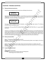
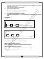
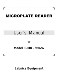
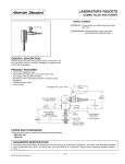
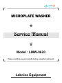
MICROPLATE WASHER
Service Manual
Model : LMW-9620
Please read this manual carefully before using the instrument
Labnics Equipment
Table of Content
Sr.No.
Contents
1
INSTRUMENT DESCRIPTION
Functions Description
Structure Introduction
Power Supply
Single Chip System
Power Supply Board
Main Board
Step Motors
Liquid-route System
Keyboard
Attached Figures
TROUBLE SHOOTING
Startup Interface Introduction
Startup Abnormalities
Liquid can not be infused
Abnormal Infusing
Declining Scouring sprayer
Microplate Holder Abnormal Movement
Sprayer Holder Abnormal Movement
Instruments going out of control while running
REPLACEMENT OF MAIN PARTS
Instrument Cover Replacement
Infusing or Ejecting Pump Replacement
Electromagnetic Valve Replacement
Holder Motor Replacement
Sprayer Motor Replacement
PCB Main Board Replacement
Power Supply Board Replacement
LCD Replacement
DETECT & ADJUST
Examine after Turning on the Instrument
LCD Contrast Adjustment
Liquid System of The Instrument
Rear View of the Instrument
Inner View of the Instrument
Components Arrangement on the Main Board
Components Arrangement on the Power Supply Board
1.1
1.2
1.2.1
1.2.2
1.2.3
1.2.4
1.2.5
1.2.6
1.2.7
1.2.8
2
2.1
2.2
2.3
2.4
2.5
2.6
2.7
2.8
3
3.1
3.2
3.3
3.4
3.5
3.6
3.7
3.8
4
4.1
4.2
Fig 1.
Fig 2.
Fig 3.
Fig 4.
Fig 5.
Pg. No.
1
1
1
1
1
1
1
1
2
2
2
3
3
3
3
4
4
4
6
6
6
6
6
7
7
7
7
7
8
8
8
8
8
9
9
10
10
CHAPTER 1. INSTRUMENT DESCRIPTION:1.1 Functions Description:
LMW-9620 Microplate Washer is an accessory for ELISA and other scientific tests. It is used in detection
processes using ELISA method, such as: removing immune reactant which is not combined; avoiding
combination between under-detected antibody and enzymatic conjugate; eliminating dissociated enzymatic
conjugate from the reaction liquid; cleaning unwanted material adsorbed on the wells of microplate in the
process of reaction. By above functions, the instrument can ensure the accuracy of results tested by ELISA
method.
The instrument uses a liquid-route system without positive or negative voltage. When instrument works, the
wash liquid will be taken out from the wash liquid bottle and through infusing system; it will be injected into the
wells of microplate. The waste liquid will be ejected out from the instrument by the ejecting system. It
absolutely conquers cross-pollution between washing liquid and waste liquid in liquid-route system.
1.2 Structure Introduction:
1.2.1 Power Supply:
The linear steady power supply provides all voltages required by the instrument. Its input voltage is
220V±10%, and its output voltages are +5V, +12V and -12V. Among these voltages, +5V is provided
for digital circuit, +12V is provided for electromagnetic valve and step motor and –5V is provided for
LCD.
1.2.2 Singlechip system:
The 78E58b singlechip acts as the main control chip. The storage units of the singlechip are “32KB
APROM” used to store the application programs and the “4KB LDROM” used to store the programs
controlling the ISP operation. The two storage units are all MTP-ROM. The 78E58b singlechip
manages LCD, keyboard, microplate holder-horizontal moving motor, sprayer vertical-moving motor,
turning on and off of all the kinds of pumps and electromagnetic valves.
1.2.3 Power Supply Board:
On the power supply board, the AC voltage is converted into DC voltage through commutating bridge,
filter network and steady circuit. The driving circuit controls turning on and off of all the kinds of pumps
and electromagnetic valves according to instructions provided by CPU main board.
1.2.4 Mainboard:
Main functions of the main board are as follows:
(1) Setting system parameters by “transfer programs set”.
(2) Controlling step motors, liquid pumps and electromagnetic valves by driving circuit.
(3) Controlling LCD.
1.2.5 Step Motors:
The instrument has two step motors: one controls the microplate holder horizontal movement, other
controls the sprayer vertical movement. The two step motors control signals are generated by P1 port
-1-
on the control unit U1 (w78e58b) of the main board and T1 signal. Ports from P10 to P13 output
pulses and T1 signal controls driving horizontal moving motor or vertical moving motor. The two
motors work together to complete washing process of all under-washing wells by rows.
1.2.6 Liquid-route System:
Liquid-route system of the instrument is composed of: valve for entering liquid (washing
liquid/distilled water), infusing pump, infusing valve, washing sprayer (8 or 12 needles) and waste
liquid valve. The entering valve can respectively controls entering of washing liquid or washing liquid
into the instrument. Infusing pump and infusing valve are used for controlling infusing liquid into wells
of the microplate. The washing sprayer is used for infusing liquid to the wells by 8 or 12 infusing
needles or sucking liquid by sucking needles. The waste liquid can be discharged by waste liquid
pump.
1.2.7 Keyboard:
Operating panel of the instrument is composed of the 6 following functional keys.
Right
Increase
Left
Pause
Decrease
Enter
Function of “Pause key” is the temporary pausing of instrument operation. If you press “Right key”
after you press Pause key, the instrument will continue working; if you press “Left key” after you
press Pause key, it will completely stop working and returns to the original state. The “Enter key” is
used for confirming your operation.
1.2.8 Attached Figures:
1.
Liquid system of the instrument. (see attached figure 1)
2.
Rear view of the instrument. (see attached figure 2)
3.
Inner view of the instrument. (see attached figure 3)
4.
Main board components arrangement. (see attached figure 4)
5.
Power supply board components arrangement. (see attached figure5)
-2-
CHAPTER 2. TROUBLE-SHOOTING:2.1 Startup Interface Introduction:
First the instrument starts then liquid crystal screen will display the main menu.
Main Menu
Wash Scour Adj
At this time the cursor will glint on “Wash”, so press Enter key to enter into washing menu. If you press the
“Right key”, Scour will be selected. Then you can scour the pipeline and if you select “Adj” and press Enter
key to confirm, the screen will display the adjusting menu.
Adj B 220 S 15
L153 D 500
The figures in above interface are just for illustration, and may not be the right numbers. The following
introduction is about the adjusting menu.
On this menu, “S” means SPACE FOR ADJUSTMENT. “B” means START POSITION; “L” means LOWER
POSITION.
The figure “15” following S is set at the time, when the instrument leaves factory. You can adjust the space of
suction needle tubes between two sucking operations by increasing or decreasing the value. The figure “220”
following B is set at the time, when the instrument leaves factory. You can adjust the space between holes of
enzymatic plate at the first row and suction needle tubes by increasing or decreasing the value. You can
increase or decrease the figure following “L” to adjust the lower position of suction needle tubes.
2.2 Startup abnormalities:
Case 1. The instrument doesn't start when turned on.
Reasons: – Either the power supply plug is not connected properly (please connect again) or the fuse is
burned out (change the fuse).
Case 2. After switching on the power supply, if lamp works properly but there is no display on the LCD.
Reasons: – Either connectors are not connected properly (so connect the connectors) or LCD is burned out
(so change the LCD).
2.3 Liquid can not be infused:
All needles do not infuse liquid.
Reasons: It may be due to the improper working of infusing pump.
Electromagnetic valve does not turn on.
-3-
Check steps and measures:
(1)
(2)
Infusing pump is not working properly:Detect the controlling signal at the connected position of the infusing pump power supply wire, when
the instrument is running. If the controlling voltage is 220V and winding of the pump is obstructed, you
should change the infusing pump.
The electromagnetic valve does not turn on:Detect the controlling signal at the connected position of the electromagnetic valve power supply
wire, when the instrument is running. If the controlling voltage is 12V and winding of the valve is
obstructed, you should change the electromagnetic valve.
2.4 Abnormal Infusing:
(1)
(2)
(3)
Asymmetric Infusing: Some needles infuse little liquid, it may be due to blocking of crystal. So you
should use medical injecting pinhead to dredge the infusing tubes and sucking tubes and then scour
the pipeline by distilled water.
If needle leaks: Either something is wrong with the electromagnetic valve or the liquid-route system
has not being shut. Then you should change the valve.
There are some air bubbles in silicon tube: (it may cause inexact infusing volume): infusing
electromagnetic valve or joints of pipeline has been leaked. Then you should find out the cause and
solve it.
2.5 Declining Scouring sprayer:
It may be caused either by bending of connected board or by loose fixing screws. You should adjust the
connected board to make it toward the scouring sprayer and check whether the screws are loose or not. After
the problem get solved, please enter the adjusting menu to adjust the position of scouring sprayer again.
2.6 Microplate Holder Abnormal Movement:
Checking flow: Loose synchronous belt → the synchronous belt and the motor shaft are not fixed → holder is
blocked → optical-coupling for limiting position shifts → motor does not rotate → abnormal power voltage →
connectors are disconnected →abnormal electric level of control pins for corresponding IC → bad step motor.
Checking steps and measures:
(a)
(b)
(c)
If synchronous belt is loose: – It may be due to loose driven synchronous shaft, so you should fix it
again and then install synchronous belt properly.
If the motor is moving: – it means that the synchronous shaft and the motor shaft are not fixed, so
please tightly screw the fixed bolt.
If the holder is locked by something, please remove it.
If motor doesn't start normally and is unsteady:
(d)
Check the reliability of the connecter.
-4-
-Check JP4, JP5 on the main board (see attached figure 5) to find out whether the pin is properly
(b)
(c)
connected to the socket or not.
-Check connections of all kinds of pins and sockets.
Check the working voltage of motor.
-Connect the black meter pen of multimeter with the ground
JP3 (V-) and connect the red meter pen with the pin JP3 (V+),
multimeter should indicate 12V.
Check the pulse on the corresponding IC control pin.
Observe the control pulse on U1 pin 1, 2, 3, 4 by the oscillograph. The following are the correct pulse
graph.
Driving Waves
V1 (Cin1, Cin2)
0
T1
V2 (Op1, Op2)
0
T2
Case 1: If the wave is correct, but the motor doesn't work properly.
Solution: Check pin 15 of U1 to find out whether the wave is correct.
Case 2: If vertical motor doesn't work properly.
Solution: Check pin 10, 12, 14, 16 of U8 to find out whether the waves are correct.
Case 3: If horizontal motor doesn't work properly.
Solution: Check pin 10, 12, 14, 16 of U8 to find out whether the waves are correct.
The motor is burned. You should change it.
-5-
2.7 Sprayer Holder Abnormal Movement:
Checking flow: loose synchronous belt → synchronous belt and motor shaft are not fixed → holder is blocked
→ optical-coupling for limiting position shifts → motor does not rotate → abnormal power voltage → connectors
are disconnected →abnormal electric level of control pins for corresponding IC → bad step motor.
2.8 Instruments going out of control while running:
It may be caused by strong electromagnetic field. Then you should turn off the instrument and take measures
to remove the disturbing element or (change the place of instrument).
CHAPTER 3. REPLACEMENT OF MAIN PARTS:3.1 Instrument Cover Replacement:(1)
(2)
(3)
Unplug AC cord from the instrument.
Unscrew the screws on both sides of the instrument.
Gently open the cover of instrument (be careful about the connected lines in the instrument).
3.2 Infusing or Ejecting Pump Replacement:(1)
Turn off the instrument and open the cover. Then you can see 3 liquid pumps in the instrument. The
two paralleled pumps are sucking pumps and above them is infusing pump as the following figure
shows.
Pump for
Infusing
Pump for
Sucking Liquid
-6-
(2)
(3)
Change the infusing pump: unplug the power supply of infusing pump from the power supply board
and unplug tubes. Unscrew the three screws and replace the old pump. Replace it with a new pump in
the opposite order.
Steps of changing the sucking pump are the same as above. But you should first remove the infusing
pump and then dismantle the sucking pump.
3.3 Electromagnetic Valve Replacement:(1)
(2)
Turn off the power supply and open the instrument cover.
Unplug the power supply of electromagnetic valve from the power supply board and unplug the tubes.
Unscrew the four screws for fixing the electromagnetic valve.
(3)
Take down the old electromagnetic valve.
12(4) Install a new pump in the opposite order.
3.4 Holder Motor Replacement:(1)
(2)
(3)
(4)
Unplug the holder motor from the main board.
Unscrew the four screws for fixing the motor.
Replace the old motor.
Install a new motor in the opposite order.
3.5 Sprayer Motor Replacement:(1) Unplug the sprayer motor from the main board.
(2) Unscrew the four screws for fixing the motor.
(3) Replace the old motor.
(4) Install a new motor in the opposite order.
3.6 PCB Main Board Replacement:(1)
(2)
(3)
Open the cover of instrument according to 3.1.
Unplug the leads connected with the main board and then unscrew the fixing screws to replace the
board.
Install and fix the new main board and connect the leads with the main board. Then switch on the
power supply to check whether voltage on the main board is correct or not.
3.7 Power Supply Board Replacement:(1)
(2)
(3)
Open the cover of instrument.
Unplug the leads connected with the power supply board and then unscrew the fixing screws to
replace the board.
Install and fix the new power supply board and connect the leads with the board. Then switch on the
power supply to check whether voltage on the board is correct or not.
-7-
3.8
LCD Replacement:(1)
Unplug the leads connected with LCD and then unscrew the four fixing screws to replace the old LCD.
(2)
Plug the leads connected with the new LCD and then turn on the instrument to check the normal
functioning of display.
(3)
Screw the four screws to fix the new LCD.
CHAPTER 4. DETECT & ADJUST:4.1
Examine after Turning on the Instrument:After the instrument is maintained, the following tests should be performed (do not install the cover and
connect the washing bottle and the distilled water).
(1)
Turn on the instrument and check whether the start-up menu of the instrument is ok.
(2)
Respectively check whether “Wash” and “Adjust” functions are working properly.
(3)
Put the plate properly and enter “Wash” program (do not connect the washing liquid). Then start the
washing program and check whether the positions of the plate holder and the sprayer are correct or
not. Otherwise you should again adjust them.
(4)
Connect the bottles of washing liquid and distilled water and then start the cleaning or washing
program and check carefully whether there is leakage of liquid or not. If yes, you should find out the
cause and remove it.
(5)
If above tests have been passed out, please turn off the power supply and install the cover. Then do
repeat the “start test” again.
4.2 LCD Contrast Adjustment:In case, readability of LCD panel needs to be improved, it is possible to adjust it by a potentiometer placed on the
PCB main board inside the instrument. The potentiometer lies in between the connected plug of LCD mainboard
and the connected plug of the power supply.
Washing Liquid
F4
Pump for
Infusing
Pump for
Ejecting Liquid
F1
F2
Bottle
for
Washing
Liquid
Bottle
for
Distilled
Water
Liquid
Bottle
for
Waste
Liquid
Needles for
Ejecting Liquid
-8-
Needles for
Infusing Liquid
Microplate
Figure 2: Rear View of the Instrument
1
2
6
①
③
⑤
5
4
3
②
④
⑥
Entrance for Washing Liquid
Entrance for Waste Liquid
Socket for Power Supply
Figure 3: Inner View of the Instrument
①
②
③
④
⑤
⑥
⑦
⑧
⑨
⑩
11
Pump for Infusing Liquid
(below it is the pump for ejecting Liquid)
Electromagnetic Valve
Sprayer Moving Module
Sprayer
Bracket for Sprayer
Microplate
Holder for Microplate
Step Motor
Power Supply Board
Main Board
LCD
-9-
Entrance for Distilled Water
Fuse
Power Supply Switch
Figure 4: Components Arrangement on the Main Board
Figure 5: Components Arrangement on the Power Supply Board
- 10 -