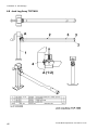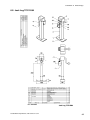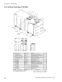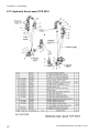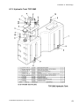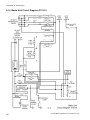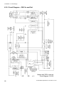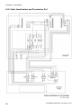
1
Lighting Tower
Workshop Manual
TCP-3247-01 Iss.B Nov 09
Taylor Construction Plant Ltd.
Quayside Industrial Park, Bates Road,
Maldon, Essex, CM9 5FA
Tel:+44 (0)1621 850777
Fax:+44 (0)1621 843330
[email protected]
www.tcp.eu.com
Contents
2
Ecolite Workshop Manual, TCP-3247-01 Iss.B
Contents
Contents
Preliminary
5
Foreword ......................................................... 5
Warranty .......................................................... 5
Liability......................................................... 5
Audits and Surveys ...................................... 5
Service and Warranty Training ..................... 5
Warranty Terms ........................................... 5
General Exclusions: ..................................... 5
Warranty Claim Submission Procedures....... 5
Certificate of Conformity................................... 6
Hatz Engine Dealers ........................................ 6
Service Bulletins .............................................. 6
Machine Identification....................................... 6
Theft Deterrence .............................................. 6
Recovery of a Stolen Machine ...................... 6
Safety .............................................................. 7
General ........................................................ 7
Fire Precautions ........................................... 7
Flammable Fluid Precautions ....................... 7
Electrical Hazard. ......................................... 8
Pre-Starting.................................................. 8
Starting ........................................................ 8
Lubrication and Servicing ............................. 8
Towing Safety .............................................. 9
Specifications................................................... 9
Section 1 Description
11
1.1 Introduction ............................................. 11
1.2 Electrics .................................................. 11
1.2.1 Ignition ............................................. 11
1.2.2 Charging Circuit................................ 12
1.2.3 Oil Pressure Light ............................. 12
1.2.4 Hours Counter .................................. 12
1.3 Lighting Supply........................................ 12
1.4 Road Running Lights............................... 12
1.5 Hydraulics ............................................... 13
Section 2 Operation
15
2.1 Daily Pre-start Inspection......................... 15
2.2 Positioning .............................................. 15
2.3 Uncoupling .............................................. 16
2.4 Jacking up the Unit.................................. 17
2.5 Using the Lights ...................................... 18
2.6 Auxiliary Supply (Optional) ...................... 19
2.7 Moving the Trailer.................................... 19
2.8 Redirecting the Lights.............................. 20
2.9 Parking.................................................... 20
2.10 Emergency Stop.................................... 20
2.11 Starting the Engine with Jumper Cables. 21
2.12 Battery Charging ................................... 21
Section 3 Maintenance
3.1
3.2
3.3
3.4
3.5
3.6
3.7
23
General ................................................... 23
Engine Maintenance................................ 23
Safety Precautions .................................. 23
Maintenance Intervals ............................. 23
Service Access........................................ 23
Lubrication .............................................. 24
General Inspection .................................. 24
Ecolite Workshop Manual TCP-3247-01 Iss.B
3.8 Daily Check............................................. 24
3.9 Engine Oil Check .................................... 24
3.10 Engine Oil Filter..................................... 25
3.11 Engine Oil Change ................................ 26
3.12 Hydraulic Fluid ...................................... 27
3.13 Fuel Filters ............................................ 27
3.14 Tyres..................................................... 28
3.15 Engine Conditioning .............................. 28
3.16 Inertia Brake.......................................... 28
3.17 Draining Fuel Tank................................ 28
3.18 Charging the Battery ............................. 29
Section 4 Fault Finding
4.1
4.2
4.3
4.4
31
Engine will not Crank............................... 31
Engine Cranks but will not Start............... 31
Battery Charging Check .......................... 31
Mast Will not Stay Up .............................. 32
Section 5 Parts Replacement
33
5.1 Recommended Tools .............................. 33
5.2 Lamp replacement .................................. 33
5.3 Housing Removal.................................... 34
5.4 Air Filter .................................................. 34
5.5 Exhaust System ...................................... 34
5.6 Fan Replacement.................................... 35
5.7 Alternator Replacement........................... 35
5.8 Engine Removal...................................... 36
5.9 Hydraulic Pump....................................... 37
5.10 AMOSS Valve Replacement.................. 37
5.11 Mast O-ring Replacement...................... 38
5.12 Mast Seal Replacement ........................ 39
5.13 Mast Flat Bar Replacement ................... 40
Section 6 Drawings
41
6.1 Rolling Chassis Assy TCP-2995 Sh A...... 41
6.2 Rolling Chassis Assy TCP-2995 Sh B...... 42
6.3 Upper Body Assy TCP-2870 Sh 1A ......... 43
6.4 Upper Body Assy TCP-2870 Sh 1B ......... 44
6.5 Upper Body Assy TCP-2870 Sh 2 ........... 45
6.6 Four-head Lamp Gimbal Assy TCP-2970 SA
Sh A .............................................................. 46
6.7 Four-head Lamp Gimbal Assy TCP-2970 SA
Sh B .............................................................. 47
6.8 Jack Leg Assy TCP1655 ......................... 48
6.9 Jack Leg TCP-2064................................. 49
6.10 SA Fuel Tank Assy TCP-2867 ............... 50
6.11 Hydraulic Schematic.............................. 51
6.12 Hydraulic Assy Layout TCP-3010 .......... 52
6.13 Hydraulic Tank TCP-2862 ..................... 53
6.14 Basic Unit Circuit Diagram 3110-01 ....... 54
6.15 Circuit Diagram – with 230V Output....... 55
6.16 Circuit Diagram – 230V In and Out ........ 56
6.17 Circuit Diagram – 110V CTE Out........... 57
6.17 Cable Identification and Termination Sh 158
6.17 Cable Identification and Termination Sh 259
6.18 Control Box Assy Tank Mounted TCP3001-01 SA.................................................... 60
6.19 Battery Kit TCP-3034 SA....................... 61
6.20 Interior Light Assy TCP-3059 SA ........... 62
6.21 Mud Flap Kit TCP-3104 ......................... 63
3
Contents
Appendix A Nut & Bolt Torque
Specification
65
1. Specific Torque Settings............................ 65
2. Generic Torque Settings............................ 65
Appendix B Options
4
Ecolite Workshop Manual, TCP-3247-01 Iss.B
Preliminary
Preliminary
Foreword
Thank you very much for purchasing this product.
We believe that it will serve you without fail. Ensure
that you read the operating instructions carefully
before use. With proper handling and maintenance,
this product will provide reliable, long-term service.
This manual is intended to serve as a manual for
workshop engineers. It assumes an engineering
knowledge commensurate with tasks that will be
undertaken in a workshop. For completeness, the
manual incorporates operating instructions
necessary to familiarise the operator and service
engineer with the controls, recommended
inspections, start-up, operating, and shutdown
procedures for the equipment.
All information, illustrations and specifications
contained in this publication are based on the latest
product information available at the time of
publication. The right is reserved to make changes
at any time without notice.
Continuing improvement and advancement of the
design may cause changes to your machine that
may not be included in this publication.
Please read the operating instructions carefully and
understand them before operating the equipment.
Warranty
Liability
The warranty period begins when the product is
delivered to and installed at the first purchaser.
Only genuine parts may be used to carry out
repairs. Failure to use only genuine parts may
invalidate the manufacturers warranty.
TCP Ltd will not be held responsible if:
• the machine has been used to perform tasks that
demand more than it’s design and strength
limitations, or
• the machine has undergone modifications not
approved by TCP Ltd, or
The warranty liability of TCP Ltd is limited to
diagnosis, repair or replacement of the defective
part, and actuating the repair - depending on the
product terms and conditions, this will be free of
charge.
TCP Ltd shall be under no liability whatever to the
customer for any indirect loss and/or expense
(including loss of profit) suffered by the customer
arising out of a breach by TCP Ltd of this contract.
Audits and Surveys
TCP Ltd reserves the right to carry out audits and
inspections from time to time in relation to any
reimbursed or outstanding warranty claims in order
to determine that all relevant details and information
is correct.
Service and Warranty Training
Service and warranty training for service fitters can
be provided at competitive rates if required. Training
can be carried out at a TCP depot or at a venue of
your choice, please contact TCP with your
requirements.
Warranty Terms
One year or 1000 hours whichever occurs first from
date of installation
All engine warranty issues must be directed to the
engine manufacturer, or the manufacturer’s
approved/appointed engine dealer.
General Exclusions:
THE FOLLOWING ARE WARRANTY
EXCLUSIONS AS DETERMINED BY HATZ:
Service items including lubricants, filters, glow
plugs, fuel injection equipment, stop solenoid/relay,
charge regulator, leaks (oil and air).
IN ADDITION: paintwork and parts that wear.
Warranty Claim Submission Procedures
• conditions of use have been abnormal, or
Claims must be reported accurately and all relevant
details given, as follows:
• normal maintenance, with regard to
requirements as set out and detailed by the
manufacturer, have not been adhered to.
OWNERS NAME AND ADDRESS: full name and address
of customer and site location, if different
TCP Ltd will not pay for normal maintenance or
servicing nor any materials used to carry out routine
servicing.
Date of Failure:
Ecolite Workshop Manual, TCP-3247-01 Iss.B
MACHINE TYPE: State machine type, i.e. Ecolite
SERIAL NUMBER: Serial number of unit
5
Preliminary
ENGINE NUMBER: Serial number of engine
HOURS USED: Sate hours used on hour clock.
Please do not guess the hours used
quote the machine model and serial number in
correspondence with your dealer or the factory.
DETAILS OF F AILURE: Give a full report on the failure
ORDER NUMBER: An order number will be required
Note that the order number is to cover the
diagnostic and call out time, as well as to determine
the following:
• That the failure is to be covered under the terms
and conditions of warranty. If this is the case,
then the costs will be covered by TCP Ltd and
the order number will not be used.
• If the failure is determined to be of a nonwarrantable nature, further authorisation to
continue will be sought before any rectification
work takes place.
The information above must be provided even if
your warranty claim is a “parts only” claim. An
invoice will be raised for the exchange parts. The
reported faulty/defective part must immediately be
returned to TCP Ltd and full inspection of the parts
carried out, if the failure is covered under the terms
and conditions of warranty a credit note
corresponding to the invoice will be despatched to
the customer. If the failure is deemed to be of a
non-warrantable nature, the invoice should be
settled immediately.
Certificate of Conformity
Each machine is issued with a certificate of
conformity that is sent to the head office of the
purchaser. Further copies are available on request
Hatz Engine Dealers
Fig 1 Data plate
Theft Deterrence
The owner/operator should take the following
precautions to discourage theft, to aid in recovery in
the event that the machine is stolen, or to reduce
vandalism.
• Remove all keys any time the machine is left
unattended.
• Immobilise the machine by removing a critical
electrical or starting system device.
• Upon receipt of a machine, record the machine
serial number and the serial numbers of allmajor components and attachments. Keep this
list up to date and filed in a safe location for fast
retrieval.
• Place a decal or notice on the machine stating
that all serial numbers are recorded.
• Discourage the thief! Inspect the gates and
fences of the machinery storage yard or
construction site. Keep machines in well-lit
areas and ask the local law enforcement
authorities to make frequent checks around the
storage yard or work site.
To locate your nearest Hatz dealer, access the
HATZ Worldwide page from the http://www.hatzdiesel.de web site.
• Liaise with neighbours. Ask them to watch
equipment left at job sites and to report any
suspicious activities to local allow enforcement
authorities.
Service Bulletins
• Make frequent inventories of machines to
promptly detect losses or vandalism.
TCP Ltd may from time to time issue service
bulletins to keep you up to date as to any
improvements or changes that may take place on
the complete assembly or component parts.
Recovery of a Stolen Machine
Machine Identification
This manual may refer to controls and equipment
that are not present on your particular machine. It is
important that you know your machine and its
equipment and how to operate it properly.
Information regarding the machine model, code and
chassis serial number is on the unit serial number
plate (Fig 1). This plate is on the front. Always
6
In the event of theft, immediately notify the law
enforcement authorities having jurisdiction. Provide
the investigating officer with name, type of
equipment, chassis and serial numbers of major
attachments and components. It would be helpful to
show the investigating officer an Operator’s
Handbook, photographs, and advertising, to
familiarise him with the appearance of the machine.
Report the theft to the insurance company. Provide
the model and all serial numbers.
Ecolite Workshop Manual, TCP-3247-01 Iss.B
Preliminary
Report the model and serial numbers of the stolen
machine to a dealer handling the respective line of
equipment. Request that the dealer forward this
same information to the equipment manufacturer.
Safety
Report all malfunctions to those responsible for
maintenance. Do not operate the equipment until
corrected. Normal service or maintenance
performed as required can prevent unexpected and
unnecessary down time. This handbook describes
general inspections, servicing and operation with
the normal safety precautions required for normal
servicing and operating conditions. It is not a guide
however, for other than normal conditions or
situations.
Operators and service engineers must be safety
conscious and alert to recognise potential operating
or servicing safety hazards at all times, and take,
necessary precautions to ensure safe operation and
servicing of the machine.
General
• Read this operator’s Handbook and learn the
operating characteristics and limitations of the
machine. Know what operating clearances the
machine requires.
• Know clearances of all side and overhead
obstructions such as wires, etc., for operating
safety.
• Be aware of operating hazards that weather
changes can create on the job. Know proper
procedures to follow when a severe rain or
electrical storm strikes.
• Know what safety equipment is required and use
it. Such equipment may be hardhat, safety
glasses, reflector type vests, respirators and
earplugs.
• Handle fuels and lubricants carefully and clean
up spills to avoid fire and slipping hazards.
• Never rush. Walk do not run.
• Ensure that the area immediately surrounding
the light tower is clean, neat and free of
debris.
• Position and operate light tower on a firm
level surface.
I
• NEVER start a unit that is in need of repair.
• Lower tower when not in use, or if high winds
or electrical storms are expected in the area.
Ecolite Workshop Manual, TCP-3247-01 Iss.B
• The tower extends up to 9 m (30 ft.). Make
sure area above the tower is open and clear of
overhead wires and obstructions.
• Bulbs become extremely hot is use! Allow bulb
and fixture to cool 10-15 minutes before handling.
• Keep area around tower clear of people while
raising and lowering mast!
• Tower must be levelled and outriggers extended before raising tower. Outriggers must
remain extended while tower is up.
• DO NOT use a lamp without the glass lens of the
lamp unit in place and undamaged. Ceramic
discharge metal halide lamps are constructed of
an outer glass bulb with an internal arc tube
made of ceramic. The arc-tubes operate at high
pressure (up to 50 p.s.i.) and at very high
temperatures. They can rupture unexpectedly
due to ballast failure or misapplication. If an arctube ruptures, it can shatter the outer glass bulb
resulting in the discharge of glass fragments and
extremely hot ceramic particles (as high as
18320F, 1000C). In the event of such rupture,
there is risk of personal injury, property damage,
burns and fire if the protective lens is not fitted.
Fire Precautions
• Clean all dirt, oil, grease and other fluids from
systems and components to minimise fire
hazards and aid in spotting loose or leaking
lines, fittings etc.
• Check the engine for rubbish, oily rags or other
debris that could cause fires before starting the
engine.
• Safely dispose of greasy, oily rags or similar
hazards.
Flammable Fluid Precautions
• Take due care when working with fuel. Diesel
fuel is a health hazard for contact with eyes or
sin, inhalation and ingestion. There is also
danger of fire and pollution.
• Don’t use diesel fuel or other flammable fluids for
cleaning purposes. Use approved nonflammable solvents.
• Make sure all-fluid systems caps, drain, valves,
fittings, lines etc., are secure and leak free.
• Shut off engine and use extra caution if engine is
hot when refuelling.
7
Preliminary
Never smoke while checking or adding fuel or
other fluid or handling fluid containers and lines.
• Use care and do not stand downwind when
adding fuel or other flammable fluids to tanks
and reservoirs to avoid fluids being blown or
splashed onto clothing.
Starting
• Do not start the engine or operate any control if
there is a ‘DO NOT OPERATE’ or similar
warning sign attached to any control.
• When preparing machines or components for
storage, seal and tape all openings and close
containers tightly to seal in all volatile inhibitor
fluids and compounds used.
• Use jumper cables only as recommended.
Improper use can result in battery explosion or
unexpected machine motion.
• DO NOT fill fuel tank near an open flame,
while smoking, or while engine is running.
Lubrication and Servicing
• DO NOT fill tank in an enclosed area with poor
ventilation.
• DO NOT run engine with the fuel tank cap loose
or missing.
• Do not allow unauthorised personnel to service
or maintain the machine. Study the Operator’s
handbook and Service Manual before starting,
operating or servicing the machine.
Electrical Hazard.
• Always relieve pressure before servicing any
pressurised system.
• Never smoke or allow open flames or sparks
near batteries.
• Use only the special hydraulic fluid supplied by
TCP. Unapproved or diluted fluid could freeze in
cold conditions resulting in damage to the
equipment and/or danger to personnel.
• Always disconnect batteries before repairing
electrical system to avoid danger of fire-causing
sparks. Disconnect battery ground cable first and
reconnect last.
• Always disconnect batteries and alternator leads
before carrying out any welding on the machine.
• Never check battery charge by placing metal
objects across battery posts to avoid sparks at
battery posts.
• Use jumper cables only as recommended.
Improper use can result in battery explosion.
• DO NOT touch or lean against hot exhaust pipes
or engine cylinder.
• HIGH VOLTAGE! This unit uses high voltage
circuits capable of causing serious injury or
death. Only a qualified electrician should
troubleshoot or repair electrical problems
occurring in this equipment.
• Replace all guards and safety devices
immediately after servicing.
• NEVER use tower if insulation on electrical
cord is cut or worn through.
• Before servicing light tower, make sure engine
start switch is turned to OFF, circuit breakers
are open (off) and the battery isolation key is
removed. NEVER perform even routine
service (oi/lfilter changes, cleaning, etc.) unless all electrical components are shut down.
• NEVER operate lights without protective lens
cover in place or with a lens cover that is
cracked or damaged!
• Never allow water to accumulate around the
base of the light tower set. If water is present,
DO NOT service!
• Make certain light tower is well grounded and
securely fastened to a good earth ground.
Pre-Starting
• If engine is to be started and run indoors, ensure
proper ventilation to remove deadly exhaust
gases.
• Always perform ‘Pre-Starting Inspection’
instructions described in this manual to ensure
the machine is ready for operation.
8
• Never service electrical components if clothing
or skin is wet. If the unit is stored outside,
check the engine and generator for any
moisture and dry the unit before use.
• Never wash the unit with a power washer or
high pressure hose.
• Open main circuit breaker before disconnecting battery cables.
• Keep hands, feet, and loose clothing away
from moving parts on generator and engine.
Ecolite Workshop Manual, TCP-3247-01 Iss.B
Preliminary
• Replace all missing and hard-to-read labels.
Labels provide important operating instructions
and warn of dangers and hazards.
Specifications
Overall length
2503 mm
• Make sure slings, chains, hooks, ramps, jacks,
and other types of lifting devices are attached
securely and have enough weight-bearing capacity to lift or hold the equipment safely.
Always remain aware of the position of other
people around you when lifting the equipment
Overall height, floodlighting position
9500 mm
Overall mast height
8740 mm
Overall height, travel position
2200 mm
Overall width, travel position
1455 mm
Overall width with jack legs
deployed
2106 mm
Tow hitch height
420 mm
Wheel size
155/ R13
Axle weight (GVM)
1000 kg
Towing Safety
Towing a trailer requires care! Both the trailer
and vehicle must be in good condition and
securely fastened to each other to reduce the
possibility of an accident.
• Check that the hitch and coupling on the towing
vehicle are rated equal to, or greater than, the
trailer's "gross vehicle weight rating" (GVWR).
• Inspect the hitch and coupling for wear or
damage. DO NOT tow trailer using defective
parts!
• Make sure the coupling is securely fastened to
the vehicle.
• Check tyres on trailer for tread wear, inflation,
and condition.
Total weight, with fuel
750 kg
Stabilizing/levelling positions
4
Lamps
4 or 6
Operating voltage
110 cte
/220V
Fuel consumption
0.5 l/hour
Fuel tank capacity
95 lts
Fuel specification: Diesel meeting EN 590,
BS 2869 A1 / A2 or ASTM D 975 - 1D / 2D
Total run time
170 hours
• Connect breakaway safety line securely to
towing vehicle.
Braking System
Fully fitted
axle braking
• Make sure directional, reverse and trailer lights
are connected and working properly.
Ground clearance
240 mm
Max wind speed for safe operation
Up to 100
kph
• Check that wheel nuts are tight and that none
are missing.
• Maximum recommended speed for highway
towing is 75 kph. Recommended maximum offroad towing speed is 15 kph (less on uneven
terrain).
Additional Safety Systems:
Automatic Mast Operating Safety System
(AMOSS) fitted as standard
• Check that the road running lights are connected
and operating, if applicable.
Ecolite Workshop Manual, TCP-3247-01 Iss.B
9
Preliminary
10
Ecolite Workshop Manual, TCP-3247-01 Iss.B
Section 1 Description
1.1 Introduction
Section 1 Description
1.1 Introduction
have a Supply Selector switch.
The Ecolite is a lighting tower designed for general
use on building sites. It features:
1.2.1 Ignition
• Four or six adjustable, ceramic discharge metal
halide lamps mounted on a telescopic tower.
• 9m tower raised and lowered using hydraulics
powered by a Hatz diesel engine.
• Lights powered from the diesel engine or
(optionally) from a local mains supply.
• Mounted on a two-wheel trailer that can either be
lifted onto a vehicle for transport or towed.
• AMOSS system prevents towing while the mast
is raised. The mast cannot be raised unless the
handbrake is on.
Engine starting is controlled by the ignition
controller (Fig 1-2). The Hatz diesel engine has no
glow plug but employs fuel-rich starting. When the
controller key switch is set to 2 (Start), the controller
applies 12V d.c. to the starter motor to turn the
engine and to a solenoid to supply fuel to the
engine. Initially the engine valves are open so that
no fuel compression occurs and the engine turns
easily. The valves remain open until the engine
reaches a pre-determined speed. At this point, the
valves close and the resultant compression ignites
the fuel and the engine starts.
The diesel engine is coupled directly to an
alternator to provide 240V a.c. power for the lights.
The hydraulic power for raising the tower is
provided by a 12V d.c. pump.
1.2 Electrics
The diagrams in this section are for explanatory
purposes only. Refer to circuit diagrams TCP-32200x in Section 6 for full information.
Versions are available with an auxiliary 230V input
and/or output. Another version incorporates a
transformer to provide a 110V (50 Hz) centretapped output. Only units with a 230V input option
Fig 1-2 Ignition Controller
Fig 1-1 Ignition circuit
Ecolite Workshop Manual, TCP-3247-01 Iss.B
11
Section 1 Description
1.3 Lighting Supply
elapsed time while the alternator is operating.
1.2.2 Charging Circuit
1.3 Lighting Supply
The engine drives an alternator to provide nominal
230V a.c. for the lights (Fig 1-4). Optionally, the
lighting supply can be obtained from an external
source connected via a socket on the case and
selected by the Supply Selector switch. Also
optionally, the generator supply can be fed to a
socket on the case. This supply can be 110V if the
optional transformer is fitted.
1.4 Road Running Lights
Some models have road running lights.
Fig 1-3 Charging circuit
The alternator unit incorporates a rectifier that
converts the a.c. from the alternator into d.c. The
regulator regulates the charging current it supplies
to the battery to maintain a full charge.
1.2.3 Oil Pressure Light
An oil pressure switch turns on the oil pressure
warning light if the oil pressure is low.
1.2.4 Hours Counter
The hours counter (Fig 1-4), powered from the
230V a.c. supply from the alternator, measures the
Fig 1-4 Lights circuit
12
Ecolite Workshop Manual, TCP-3247-01 Iss.B
Section 1 Description
1.5 Hydraulics
Fig 1-5 Hydraulics
1.5 Hydraulics
Refer to the Hydraulic Schematic drawing Fig 1-5.
The mast contains concentric, telescopic hydraulic
cylinders and is raised by pumping hydraulic fluid
into the cylinders. A one-way valve holds the
pressure up when the pump is not operating so that
the mast will stay up. A solenoid valve lowers the
mast by routing the pressurised fluid back to the
tank.
The Raise/Lower switch activates the pump motor
solenoid to raise the mast or activates the Lowering
valve to lower it. The Interlock relay ensures that
the mast can only be raised or lowered if the 230V
supply from the alternator is present – meaning that
the engine is running to keep the battery charged
for raising the mast.
The function of the AMOSS valve is to prevent the
unit being moved while the tower is raised. A rod
links the handbrake to the AMOSS valve so that if
the brake is off, any pressure in the mast cylinders
is relieved and the mast comes down. A spring
operates on the valve to allow the mast to rise.
When the handbrake is off, the rod operates against
the spring to prevent raising of the mast. As long as
the hand brake is on, the mast can be raised and
lowered normally.
Ecolite Workshop Manual, TCP-3247-01 Iss.B
13
Section 1 Description
1.5 Hydraulics
14
Ecolite Workshop Manual, TCP-3247-01 Iss.B
Section 2 Operation
Section 2 Operation
2.1 Daily Pre-start Inspection
2.2 Positioning
These instructions must be carried out to assure
continuance of engine warranty.
When choosing a location of the Ecolite, bear in
mind the following:
Full routine maintenance procedures are given in
Section 3 Maintenance.
• The light tower should not be placed where
those working under the light are:
1.
Ensure that the machine is ready for
operation before the starting it.
2.
The machine should be in a level position to
permit accurate checking of fluid quantities in
the engine and other components.
3.
Open the left hand side of the engine
enclosure to access to the engine for routine
maintenance.
Note:
4.
Refer to the engine manufacture’s
handbook for engine maintenance details.
Engine - With engine off, check oil level. The
oil should be just over the top thread at filler
Add oil if low. (See Table 3-2 for correct oil).
5.
Inspect the engine air cleaner for any
damage. (If damaged, replace it immediately.
Using an engine with a damaged air cleaner
will seriously reduce engine life).
6.
Check that oil cooler outlet grill (between
body and chassis) is clear of obstructions.
7.
Inspect for any leaks whether fuel, engine oil
or hydraulic oil.
8.
Check fuel level.
To prevent condensation from contaminating the
fuel, fill the fuel tank at end of each shift.
o
Forced to look into the light regularly or
o
Forced to work with their backs to the light
(shadows will block the light from the work
area).
• Assess site conditions carefully before
positioning and operating the tower.
• Do not position the tower in the vicinity of
overhead cables or power lines!
• Locate the light tower on the same or a higher
level than the area being lit (the higher the
light, the less shadow length).
• The area where the tower is positioned should
be relatively level. This will ensure smooth,
trouble-free telescoping of the mast. (The
mast may not telescope down properly if the
unit is not level.)
• Put the handbrake on before attempting to
raise the mast. The mast cannot be raised
unless the handbrake is on.
• Do not move the tower with the mast raised!
(The mast will telescope down automatically if
the brake is released).
• Never raise the mast or operate the tower
without the jacklegs touching the ground!
The Ecolite would normally be towed into the
required position and then uncoupled from the
towing vehicle. However, the Ecolite has a lifting
point for use with a crane and two pockets for use
with a forklift (Fig 2-1) that can be used.
Fig 2-1 Lifting points
Ecolite Workshop Manual, TCP-3247-01 Iss.B
15
Section 2 Operation
2.3 Uncoupling
Do not release the Jockey
Wheel Assy. Clamp Lever while the Jockey Wheel
is taking the weight of the unit. The unit would tip
forward and could cause damage or personal
injury.
Uncouple the Ecolite trailer from the towing
vehicle, if necessary, as follows:
9.
Apply the parking brake by pulling up the
lever (Fig 2-2). The mast cannot be raised
unless the brake is on.
10. Disconnect the trailer lighting from the towing
vehicle.
11. Detach the breakaway cable from the towing
vehicle.
12. Release the jockey wheel assembly clamp
and lower the wheel approximately half way
to the ground.
13. Retighten the clamp.
14. Wind the jockey wheel down to release the
weight from the towing eye.
15. Release and remove the pin from the towing
eye on the towing vehicle.
16. Make any final adjustments to the position of
the unit and apply the parking brake by
pulling the lever upward to the limit of its
travel.
Fig 2-2 Parking brake
Coupling the unit to a towing vehicle is the reverse
of this procedure. Before moving off, check the
tyres and check that the lights on the trailer work.
16
Ecolite Workshop Manual, TCP-3247-01 Iss.B
Section 2 Operation
Fig 2-3 Jack components
2.4 Jacking up the Unit
Jack up the unit as follows. Start with the jack
that is on the highest ground.
1.
2.
Pull out the Outrigger Locking Pin (Fig 2-5 )
and pull the Jack Leg away from the body of
the unit to its fullest extent (Fig 2-6).
Hold the Jack Leg with one hand and pull the
Rotation Locking pin to release the leg.
Allow the leg to fall to the vertical position.
Ensure that the pin locks the leg in the
vertical position (Fig 2-4).
Fig 2-4 Jack vertical
Fig 2-5 Extending the jack
Ecolite Workshop Manual, TCP-3247-01 Iss.B
17
Section 2 Operation
3.
Wind the foot of the jack down to the ground
(Fig 2-7).
Fig 2-13 Control panel
Fig 2-7 Jacking up
Fig 2-14 Ignition panel
Repeat the procedure for all four jacks so that the
unit is stable and level. Do not use the jacks to
raise the tyres off the ground.
Note:
2.5 Using the Lights
7.
Check that the main switch and miniature
circuit breakers (MCBs) are on (up) and the
Light switches are off. (The main switch is a
residual current device (RCD) that can be
tripped by an earth leakage.)
8.
Set the Supply Selector Switch (if fitted) to
Off.
Insert the key in the Key Switch and turn it to
position 1. The Battery and Oil Pressure
lights adjacent to the switch should light.
1.
Check that the brake is on. Note that the
mast cannot be raised if the brake is off.
Check that the brakes are operating correctly
on both wheels by attempting to move the
trailer.
Fig 2-13 shows a 230V machine with an
auxiliary output. The mcb configuration
on other versions will be different.
2.
Check that the light lenses are clean and
undamaged.
9.
3.
Drive the earth spike (Fig 2-14) into the
ground (earth) (follow any risk assessment).
Check that the earth spike cable is securely
attached to the unit.
10. Turn the key to position 2.
4.
Check that the Emergency Stop button is not
pressed. If necessary, rotate the button
clockwise to release it.
5.
Open the cover to access the Control Panel.
6.
Check the fuel level and top up if necessary.
(The fuel level can be seen through the
translucent fuel tank.)
18
11. As soon as the engine starts, release the Key
to position 1. Check that the Battery and Oil
Pressure lights go out and the green,
Running light remains on.
Note:
If the engine does not start, return the key
switch to position 0 before retrying.
12. Check that the lights on the tower are
oriented so as to provide optimum
illumination of the site. The lights can be
tipped up/down and rotated, as required. It is
also possible rotate the tower through 300
degrees. See Section
Ecolite Workshop Manual, TCP-3247-01 Iss.B
Section 2 Operation
2.8 Redirecting the Lights.
13. Raise the tower by turning the Tower switch
clockwise and holding it there.
14. Release the Tower switch when the lights
reach either the required height or maximum.
You will hear a change in the pitch of the
hydraulic motor when the mast is fully
extended.
Note:
It is normal for the mast to appear wet as
it is raised: the hydraulic fluid acts as a
lubricant for the seals between the
telescopic sections. Subsequent leakage
from a raised mast could indicate a
problem with a seal. Seals and O-rings
can be replaced as detailed in Sections
5.11 Mast O-ring Replacement and 5.12
Mast Seal Replacement.
15. Set the Supply Selector switch (if fitted) to
Generator.
To use the auxiliary supply, follow the instructions
given in Section 2.5 Using the Lights but set the
Supply Selector switch to Aux Input in Step 15.
On completion, turn off the generator, leaving the
lights powered from the Auxiliary mains input.
Where an output socket is fitted, it provides either
110V centre-tap earth (cte) or 220V output
(depending on version/region) from the internal
alternator.
2.7 Moving the Trailer
The trailer cannot be moved with the tower raised.
(Releasing the brake causes the tower to
telescope down.) To move the trailer:
1.
Turn off the lights and allow time for them to
cool.
2.
Lower the tower.
3.
Ensure that the jockey wheel is down and
locked so that the unit will not tip over when
the jacks are removed.
4.
Raise, retract and stow the four jacks.
5.
Ensure mast rotation clamp is secure, to
prevent movement in transit.
16. Set the Light switches to On (clockwise).
The lamps take a minute or two to warm up.
17. Close the cover to protect the Control Panel.
Closing down the unit is the reverse of this
procedure.
Before lowering the tower, switch off the lights and
allow time for them to cool.
To stop the engine, turn the Key Switch to 0.
2.6 Auxiliary Supply (Optional)
Where an input plug is fitted (Fig 2-15), the lamps
can be powered from a local mains supply instead
of from the generator. Connect the mains supply
to the Aux input plug (Fig 2-15).
The unit can be either manhandled or towed to
the new location.
Before towing:
• Check that the hitch and coupling on the
towing vehicle are rated equal to, or greater
than, the trailer's "gross vehicle weight rating"
(GVWR).
• Inspect the hitch and coupling for wear or
damage. DO NOT tow trailer using defective
parts!
• Make sure the coupling is securely fastened to
the vehicle.
• Check tyres on trailer for tread wear, inflation,
and condition.
• Connect breakaway safety line securely to
towing vehicle.
• Make sure directional, reverse and trailer lights
are connected and working properly.
• Check that wheel nuts are tight and that none
are missing.
• Connect the road running lights, if applicable,
and check that they work.
Fig 2-15 Auxiliary supply connectors
Note:
To avoid depleting the battery, the unit is
configured so that the mast can only be
raised with the engine running.
Ecolite Workshop Manual, TCP-3247-01 Iss.B
The maximum recommended speed for highway
towing is 75 kph. Recommended maximum offroad towing speed is 15 kph (less on uneven
terrain).
19
Section 2 Operation
2.8 Redirecting the Lights
The tower can be rotated through up to 300
degrees so as to direct the light as required.
Slacken the Rotation Lock (Fig 2-14) and turn the
Rotation Handle so as to direct the lights as
required. Tighten the lock afterwards.
In addition to rotation of the mast, each of the
lights can be rotated on two axes and tipped back
and forth (Fig 2-17). Thus the lights can be
directed either downwards or horizontally (e.g. to
illuminate a facade (Fig 2-16)). For any
adjustments, the mast must be lowered to allow
access.
Fig 2-16 Façade illumination
2.9 Parking
When parking the machine
overnight or for an extended period, the following
procedure will help maintain it in good condition:
1.
To prevent condensation from contaminating
the fuel, fill the fuel tank completely before
parking the machine overnight or for
extended periods. If a security kit is
supplied, keep it locked
2.
Park on level ground where possible. If it
must be parked on a slope, position machine
at right angles to the slope and block tracks
securely.
3.
Remove key to a place of safety
Fig 2-17 Light manipulation
2.10 Emergency Stop
The Emergency Stop button (Fig 2-18) shuts off
the engine in under 20 seconds.
Fig 2-14 Rotation lock
Fig 2-18 Emergency Stop button
20
Ecolite Workshop Manual, TCP-3247-01 Iss.B
Section 2 Operation
The engine (and the power it generates) will
remain off until the Emergency Stop button is
released. To release the button, twist it in the
direction of the arrows on the button.
There is also an emergency stop inside the cover
(Fig 2-20). Pull the knob to cut off the fuel to the
engine, which will stop after a short delay.
2.11 Starting the Engine with
Jumper Cables.
For jump starting, jumper cables can be connect
can be connected to stud terminals on the side of
the engine compartment Fig (2-20). To access
these terminals, open the left hand side of the
enclosure.
Do not jump start a vehicle by using arc welding
equipment. Currents and voltages are
dangerously high and cannot be sufficiently
reduced to make the method safe.
Be sure machines are not touching each other.
Use cables that are the same size as those on the
machine.
5.
Keep grounding point clear of battery so that
if a spark occurs, it is away from battery
fumes (explosive hydrogen).
6.
Locate cause of battery failure.
2.12 Battery Charging
If the battery is not being charged properly, refer
to Section 4.3 Battery Charging Check. The
battery can be charged from the mains as detailed
in Section 3.18 Charging the Battery.
Charging of Odyssey Batteries
Check polarity of discharged battery connections.
Do not allow charging voltage to exceed 15 volts.
Excessive booster voltage and/or incorrect jumper
cable connections will destroy plates inside
battery.
Keep all sources of ignition away from batteries.
Do not lean over batteries.
Do not allow the battery to become fully
discharged. The battery may no be able to
recover from this state, rendering it unserviceable.
If jumper cables are used to start an engine, be
sure to follow this procedure:
1.
Connect one end of the jumper cable, usually
coloured red, to the + battery supply stud
terminal (Fig 2-20).
Note:
Voltmeter
Reading
State of
charge
12.84 Volts
100%
12.50 Volts
75%
12.18 Volts
50%
11.88 Volts
25%
When Ecolite power is supplied from an
outside source via the input socket
(engine not used and supply Selector
switch set to Auxiliary), the Emergency
Stop button is inoperative and will not turn
off the power.
The RCD provides protection against
electric shock.
Fig 2-20 Internal Emergency Stop
2.
Connect the other end of the same cable to
the ‘POSITIVE’ (+) post on the booster or
charged battery.
3.
Connect one end of the second cable,
usually coloured black to the NEGATIVE’ (-)
post of the booster battery.
4.
Connect one end of the jumper cable to the battery supply stud terminal or to a
convenient point on the engine frame.
Ecolite Workshop Manual, TCP-3247-01 Iss.B
21
Section 2 Operation
22
Ecolite Workshop Manual, TCP-3247-01 Iss.B
Section 3 Maintenance
Section 3 Maintenance
Service interval
Every
Every
500 hr
1000 hr
Every
Operation
Daily
250 hr
Engine Oil
Check
Change
Air filter
Check/replace
Fuel Filter – in-line
Replace
Fuel Filter – fixed
Replace
Hydraulic fluid
Check
Engine oil filter
Clean
Lubricate inertia
Grease
brake
Drain fuel tank
Annually
Engine conditioning
* Check/replace air filter daily if operating in dusty conditions
Every
1500 hr
Ref.
Page
24
34
27
27
27
24
28
Decoke
28
28
Table 3-1 |Maintenance Intervals
3.1 General
3.3 Safety Precautions
Lubrication is an essential part of preventive
maintenance. It is important that the instructions
regarding types of lubricants and the frequency of
their application be followed to prolong the useful
life of the machine. Periodic lubrications of moving
parts reduce mechanical failures.
• Do not allow unauthorised personnel to service
or maintain this machine.
While servicing, thoroughly clean all fittings, caps,
plugs etc., to prevent dirt from entering the system.
• Study the manual before starting, operating or
servicing this machine. Always follow the
procedures and safety precautions detailed in
this manual.
Lubricants must be at operating temperatures
before draining.
• Do not work under or near any unblocked or
unsupported linkage, or any part of machine.
Do not operate any system unless oil level is within
the operating range as indicated on the dipstick or
level plug.
• Always shut down machine before cleaning,
lubricating or servicing the machine
All change and service periods are
recommendations based on average operating
conditions. Lubricants showing evidence of
excessive heat, oxidation or dirt should be changed
more frequently to prevent these conditions.
Lubricants change and service periods must be
established on the basis of individual job conditions.
3.2 Engine Maintenance
Since the workshop manual provided by the engine
manufacturer contains comprehensive information
on servicing the engine, this Routine Maintenance
section only provides information on the engine for
daily servicing and where it differs from the
standard application covered by the engine
workshop manual. Refer to the manufacturer’s
manual for all other information and instructions
relating to the engine.
Ecolite Workshop Manual, TCP-3247-01 Iss.B
• Always relieve pressure before servicing any
pressurised system.
• Always attach a ‘DO NOT OPERATE’ or similar
warning sign to ignition switch or a control before
cleaning or servicing the machine.
• The ceramic insulation wrapped around the
exhaust pipe and the engine cover ceramic heat
barrier are made of toxic material – possible, low
risk carcinogenic. Minimise dust release and
use appropriate ‘Personal Protection Equipment’
when handling them.
3.4 Maintenance Intervals
Table 3-1 lists the maintenance intervals.
3.5 Service Access
To access the engine for routine maintenance, open
both sides of the engine enclosure.
23
Section 3 Maintenance
Item
Component
Lubricant
1
Engine Crankcase
and Filter
Engine Oil
2
Hydraulic System
Hydraulic fluid
3
Fuel tank
Diesel Fuel Oil with
max. Sulphur 0.5%
4
Towbar greasing
Morris Lubricants K2 EP
Specifications
API
Code
1.85% max. sulphated ash limit
CC/CD
SAE
Grade
10W-30
Ecolite Mast Fluid TCP Part
No. 80-0372
A.S.T.M. No.2 Diesel Fuel at
sub zero temp. blend No. 2 with
No.1
Multipurpose Lithiium grease
NLGI No.2
Table 3-2 Recommended lubricants
3.6 Lubrication
Grease the tow bar coupling at least once per year
– more frequently if the unit is towed frequently.
3.7 General Inspection
Note:
• Service air cleaners more often when operating
under extremely dusty conditions.
• Do not wash the air cleaner element out with
detergent. Replace with new.
• Engine air intake. Check air intake system for
wear or damage to piping, loose clamps and
leaks.
3.9 Engine Oil Check
• Check for loose bolts or fixings. Tighten as per
bolt chart in Appendix A.
1.
Ensure that the unit is level.
2.
Switch off the engine.
• Check for oil leaks. Securely tighten any loose
joints and replenish any losses:
3.
Clean the area around the oil filler cap/dipstick.
4.
Remove the dipstick (Fig 3-8) and allow a few
moments for the oil level to settle.
5.
Check the oil level using the dipstick
(Fig 3-1).
6.
If necessary, top up the oil (see Fig 3-9). Do
not overfill.
• Examine the body, particularly the chassis, for
cracks or broken welds. Repair where
necessary.
Check the engine oil after each day’s use.
Fig 3-1 Dipstick levels
3.8 Daily Check
After every 10 hours of operation, do a walk-around
inspection:
• Visually check engine for damage, listen for any
unusual noises:
• Engine Air Cleaner, Inspect and remove any
obstructions from the air cleaner inlet with the
engine stopped:
• Check Engine oil level. See Section 3.9 Engine
Oil Check.
Fig 3-1 Engine side panel
24
Ecolite Workshop Manual, TCP-3247-01 Iss.B
Section 3 Maintenance
3.10 Engine Oil Filter
Clean the oil filter after every 1000 operating hours.
1.
To gain access to the oil filter it is necessary to
remove the side panel from the engine. Fig 31 shows the side panel and some of the fixing
screws. The oil filter is located near the bottom
of the engine (Fig 3-3).
Fig 3-5 Oil filter extraction
Fig 3-3 Engine oil filter
2.
Use an Allen key to remove the filter (Fig 3-4)
and extract it (Fig 3-5).
3.
Wash out oil filter with degreaser. Replace
filter if damaged.
4.
Check joint washers (Fig 3-6). Replace if
necessary.
5.
Lubricate joint washers before fitting.
6.
Insert filter to limit of travel. Ensure that
tension springs (Fig 3-7) sit close to filter
before tightening screw.
Fig 3-6 Oil filter washers
Fig 3-7 Oil filter spring
7.
Unless doing an oil change, check oil level and
top up as necessary.
Fig 3-4 Unscrewing oil filter
Ecolite Workshop Manual, TCP-3247-01 Iss.B
25
Section 3 Maintenance
3.11 Engine Oil Change
Parts: Oil filter TCP
Change the oil every 250 operating hours.
Take care that no contamination enters the sump
1.
Ensure that the unit is level.
2.
Run the engine until it is warm.
3.
Clean the area around the oil filler
cap/dipstick.
4.
Remove the filler cap/dipstick (Fig 3-8).
5.
Attach a suitable tube to the oil evacuation
pump and route it to a suitable container.
6.
Use the hand pump to evacuate all the oil
from the sump.
7.
Disconnect the tube.
8.
Refill the sump with oil of the correct grade for
the conditions (Fig 3-9) to the correct level, as
indicated on the dipstick.
9.
Refit the filler cap/dipstick.
Fig 3-9 Oil SAE grades
Oil should meet at least one of the following
specifications:
ACEA – B2 / E2 or better
API – CD / CE / CF / CF-4 / CG-4 or better.
If engine oil of a poorer quality is used, reduce oil
change interval to 150 hours of operation.
Fig 3-8 Oil filler/dipstick and pump
26
Ecolite Workshop Manual, TCP-3247-01 Iss.B
Section 3 Maintenance
3.12 Hydraulic Fluid
Check the fluid in the hydraulic tank daily.
Remove the cap from the hydraulic tank and check
the level. The fluid should just reach the bottom of
the filter that is under the cap (Fig 3-10). If
necessary, top up with Ecolite Mast Fluid (TCP Part
No. 80-0372).
: Only use the specified TCP
hydraulic fluid (undiluted). This fluid is specially
formulated for the purpose. If the wrong fluid is
used or the fluid becomes diluted, it could freeze
under cold conditions with resultant structural
damage to the equipment. This could result in
injuries to personnel and/or damage to property.
If it is suspected that the fluid has become diluted,
drain the tank (as described for the fuel, in Section
3.17 Draining Fuel Tank) and refill with the
prescribed TCP fluid.
Take care not to mix fuel and hydraulic fluid.
3.13 Fuel Filters
Parts:
In-line fuel filter TCP 14-0131
Fixed fuel filter TCP 14-0128
Take due care when working with
fuel. Diesel fuel is a health hazard for contact with
eyes or sin, inhalation and ingestion. There is also
danger of fire and pollution.
Dirty or contaminated fuel will damage the engine.
For this reason, three fuel filters are fitted, as
follows:
Two fuel filters are fitted: one on top of the fuel
tank, in the line to the fuel pump (Fig 3-12) and the
other mounted on the side of the engine
compartment (Fig 3-13). Replace the in-line filter
after 250 hours of operation and the fixed filter after
500 hours.
Fig 3-10 Hydraulic fluid level check
Fig 3-11 Hydraulics
Ecolite Workshop Manual, TCP-3247-01 Iss.B
27
Section 3 Maintenance
3.16 Inertia Brake
The inertia brake applies the trailer brakes when the
towing vehicle brakes.
Apply medium multipurpose grease to the nipples
(Fig 3-14).
Fig 3-12 In-line fuel filter
Fig 3-14 Inertia brake grease nipples
The frequency of greasing depends on the extent of
towing. If the trailer is towed frequently, with
frequent braking, the brake will need more frequent
greasing than if the brake is seldom used.
Fig 3-13 Fixed fuel filter
3.14 Tyres
Check the condition of the tyres. They should meet
local wear regulations if used on public roads.
Check the tyre pressures They should be 2.5 bar
(35 psi).
3.15 Engine Conditioning
After every 1500 hours of operation, the engine
should be run under a 2.6 kW load for two hours in
order to clear it of accumulated carbon deposits.
The 2.6 kW can comprise a 2 kW load connected to
the Auxiliary Supply output plus 600W for the lights.
28
Inspect the brake every three months. If adequate
lubricant is showing, grease annually.
3.17 Draining Fuel Tank
When working on the fuel system, do not expose it
to a naked flame; do not smoke.
Over time, condensation results in a layer of water
forming at the bottom of the fuel tank, water being
heavier than diesel fuel. Once per year, remove the
water as follows:
1.
Fit a polyethylene tube (diameter 4 mm, length
700mm approx.) to a commercial syringe (20
ml or larger).
2.
Remove the diesel filler cap and run the tube
down to the bottom of the tank.
3.
Drain off the fuel/water mixture with the
syringe.
4.
Repeat the procedure until the transparent
syringe is found to contain only diesel fuel.
Ecolite Workshop Manual, TCP-3247-01 Iss.B
Section 3 Maintenance
3.18 Charging the Battery
The battery can be charged by means of a standard
12V car battery charger. Connect the charger
between positive and negative battery stud
terminals or between the positive stud and engine
chassis (negative) (Fig 3-15).
Fig 3-15 Battery test stud
Ecolite Workshop Manual, TCP-3247-01 Iss.B
29
Section 3 Maintenance
30
Ecolite Workshop Manual, TCP-3247-01 Iss.B
Section 4 Fault Finding
Section 4 Fault Finding
4.1 Engine will not Crank
The ignition controller (Fig 1-2) controls engine
starting. The Hatz diesel engine has no glow plug
but employs fuel-rich starting. At startup, the
engine valves initially open so that no fuel
compression occurs and the starter motor turns the
engine easily. The resultant compression ignites
the fuel and the engine starts.
If the battery voltage is low, the controller releases a
solenoid, which cuts off the fuel supply to the
engine so that the engine will not start. Similarly, if
the engine is running and the battery voltage falls
below the acceptable threshold, the engine will
stop. This could occur if the mast were raised
repeatedly within too short a time for the battery to
recharge.
1.
Check that Emergency Stop button is released.
2.
Check that Supply Selector switch is set to
Generator.
3.
Check that Supply Isolator switch (if fitted) is
on.
4.
Check the battery connections.
5.
Check the battery voltage with the ignition
switch off. This can be measured between the
battery test studs shown in Fig 4-1.
Fig 4-1 Battery test stud
The battery voltage varies with charge as follows:
Voltmeter reading
12.84V
12.50V
12.2V
11.9V
State of charge
100%
75%
50%
25%
If a charging problem is suspected, check the
charging circuit as detailed in Section 4.3 Battery
Charging Check.
6.
Check starter motor.
4.2 Engine Cranks but will not
Start
1.
Check fuel amount and quality.
2.
Check that the emergency Pull to Stop button
on the engine compartment is fully in.
3.
Check that the electric fuel pump is running. It
should produce audible clicking.
4.
Check battery voltage as detailed in Section
4.1 Engine will not Crank.
5.
To check for water in the base of the fuel filter,
unscrew the tap on the underside of the filter.
Use a container to catch any water or fuel that
comes out.
6.
Check the fuel valve, accessed by removing
the side panel of the engine compartment. The
valve should produce an audible click when the
ignition is turned on. Check the continuity of
the valve solenoid.
Fig 4-2 Fuel valve
4.3 Battery Charging Check
The battery is charged from an a.c. alternator driven
by the engine. A regulator converts the a.c. to a
d.c. charging current, which it regulates to ensure a
full battery charge.
To check charging, start the engine and measure
the battery voltage. The charging voltage should be
of the order of 14V. If the battery voltage has not
Ecolite Workshop Manual, TCP-3247-01 Iss.B
31
Section 4 Fault Finding
increased significantly from its off-load value,
suspect an alternator, regulator or wiring problem.
To check the alternator, switch off the engine,
disconnect the connections to the alternator and
connect an d.c. voltmeter to the alternator. Start the
engine and measure the (off-load) output from the
alternator, this should be more than 14V d.c.
If the alternator output is correct, check the
regulator and wiring as detailed in the engine
workshop manual.
32
4.4 Mast Will not Stay Up
Check that the handbrake is fully on.
Check that the linkage to the handbrake is correctly
operating the AMOSS valve under the tow bar.
Check for leakage around the mast segments. If
necessary, replace the relevant seals on the mast
(See Section 5.12 Mast Seal Replacement ).
Ecolite Workshop Manual, TCP-3247-01 Iss.B
Section 5 Parts Replacement
Section 5 Parts Replacement
5.1 Recommended Tools
• Crows foot 32 mm spanner
5.2 Lamp replacement
Note:
1.
Do not touch the lamp bulb with bare
fingers. The grease deposited from skin
will cause the lamp to fail when it is turned
on. Ensure that the new lamp is clean.
Release the clips securing the lens (Fig 5-1)
and remove the lens (Fig 5-2).
Fig 5-2 Lamp lens
2.
Unclip the lamp from the holder (Fig 3-3).
3.
Install the new lamp and refit the lens.
Fig 5-1 Lens clips
Fig 3-3 Lamp and holder
Ecolite Workshop Manual, TCP-3247-01 Iss.B
33
Section 5 Parts Replacement
5.3 Housing Removal
The housing is held in place by the lifting frame.
1.
Release the lifting frame by removing the two
bolts at the rear (Fig 5-4) and the single bolt
at the front (Fig 5-3)
2.
If necessary, disconnect the licence plate
wiring.
3.
Remove the lifting frame and lift off the
housing.
Fig 5-6 Air filter element
Refitting is the reverse of this procedure.
Fig 5-3 Lifting frame front fixing
Fig 5-7 Safety element
Check the air filter every 250 operating hours daily under dusty conditions. The filter comprises
an outer filter element and an inner safety
element, intended to stop the filter element being
sucked in.
Fig 5-4 Lifting frame rear fixing
5.4 Air Filter
Parts:
Air filter element
Safety element
TCP 10-0273
TCP 10-0274
1.
Open the cover to access the air filter
assembly.
2.
Unscrew the air filter cover (Fig 5-5).
3.
Extract the filter element (Fig 5-6).
4.
Extract the inner, safety element (Fig 5-7).
5.
Replace filter if damaged or dirty.
6.
Reassemble the filter assembly.
5.5 Exhaust System
The ceramic wrapping on the exhaust pipe is toxic
– possible, low risk carcinogenic. Minimise dust
release and use appropriate personal protection
equipment when handling it.
Fig 5-5 Air filter cover removal
34
Parts:
10-2924
10-3003
10-2962
10-2878
10-3032
Silencer
Exhaust Flexible Pipe
Exhaust Elbow
Exhaust Outlet Pipe
Silencer + Spark Arrestor MS
Ecolite Workshop Manual, TCP-3247-01 Iss.B
Section 5 Parts Replacement
1.
Release the clamp securing the exhaust
chamber to the down pipe on the underside
of the unit.
5.7 Alternator Replacement
1.
Ensure that the engine is switched off.
Remove and pocket the key.
2.
Isolate the battery by disconnecting the
negative terminal of the battery.
3.
Remove the enclosure as detailed in Section
5.3 Housing Removal.
4.
Remove the side, top and fan panels from
the engine compartment.
5.
Unbolt Hatz engine controller from control
panel and lift away with engine pod.
6.
Disconnect cables from alternator (white
multi-connector).
Fitting the exhaust is the reverse of this
procedure.
7.
Remove the two or four screws securing the
alternator vibration mount(s) to the base.
5.6 Fan Replacement
8.
Remove the four screws securing the
alternator to the engine.
2.
Remove the four screws securing the
exhaust chamber (Fig 5-8) and remove the
chamber.
Fig 5-8 Exhaust chamber fixing points
To replace the fan on the engine compartment:
1.
Ensure that the engine is switched off.
Remove and pocket the key.
2.
Isolate the battery by disconnecting the
negative terminal of the battery.
3.
Remove the enclosure as detailed in Section
5.3 Housing Removal.
4.
Remove the side panels from the engine
compartment.
5.
Remove the concertina hose from the fan.
6.
Remove the panel on which the fan is
mounted.
Fig 5-10 Fan
9.
Remove the alternator end cap (two screws).
10. Unscrew the tie bolt that passes through the
centre of the alternator.
The next step is to disconnect the alternator from
the motor, which drives the alternator via a
tapered shaft (Fig 5-11).
Fig 5-9 Fan
7.
Disconnect the fan supply leads. The red
lead unplugs from a free socket. The black
lead is attached to the alternator frame.
8.
Remove the fan from the panel (four screws).
Fitting the new fan is the reverse of this
procedure.
Fig 5-11 Drive shaft on alternator
Ecolite Workshop Manual, TCP-3247-01 Iss.B
35
Section 5 Parts Replacement
11. Screw the tie bolt two turns back into the
shaft. While pulling the alternator away from
the engine, tap sharply on the end of tie bolt
with a copper mallet to release the shaft from
the taper. If necessary, use a pry bar in the
gap between the alternator and the engine to
prise them apart while tapping the bolt.
Fitting the new alternator is the reverse of this
procedure.
5.8 Engine Removal
Fig 5-13 Engine exhaust outlet
7.
Disconnect the fuel lines.
Take due care when working with fuel. Diesel
fuel is a health hazard for contact with eyes or
sin, inhalation and ingestion. There is also
danger of fire and pollution.
The engine is heavy. Use appropriate lifting
equipment and/or get the necessary help.
1.
Ensure that the engine is switched off.
Remove and pocket the key.
2.
Isolate the battery by disconnecting the
negative terminal of the battery.
3.
Remove the enclosure as detailed in Section
5.3 Housing Removal.
4.
Remove the four bolts securing the engine
pod to the Ecolite chassis.
5.
Disconnect the lead to the alternator from the
terminal block attached to the underside of
the plate on the top corner of the engine pod
(Fig 5-12) and extract the lead from the
engine pod.
Fig 5-14 Fuel lines
8.
Disconnect the concertina duct from the
engine extractor fan.
Fig 5-15 Engine extractor duct
9.
Attach the hoist straps to the lifting eyes of
the engine pod.
10. Lift the pod out and deposit it on a bench
working area.
11. Remove the two screws securing the dip
stick and pump assembly to the panel.
Fig 5-12 Alternator connector block
6.
Disconnect the exhaust at the elbow where
the pipe leaves the engine pod.
Fig 5-16 Dipstick securing screws
36
Ecolite Workshop Manual, TCP-3247-01 Iss.B
Section 5 Parts Replacement
12. Tip the engine pod on its side to reveal the
sump cover.
13. Disconnect the sump adaptor from the dipstick assembly (Fig 5-18).
A
B
Fig 5-21 Disconnecting pump assembly
6.
Fig 5-19 Sump cover and adaptor hose
Remove the four screws securing the pump
assembly to the tank
14. Remove the sump cover from the frame.
15. Remove the hose from the sump adaptor and
unscrew the sump adaptor from the sump.
Fig 5-22 Pump screws
7.
Fig 5-18 Sump adaptor
16. Remove the four bolts securing the engine to
the pod and lift out the engine.
17. Remove the alternator from the engine as
described in Section 5.7 Alternator
Replacement.
Fitting the new engine is the reverse of this
procedure. Fit the sump adaptor and hose from
the old engine to the sump of the new engine.
Carefully lift out the pump, taking care not to
to observe the safety precautions appropriate
to the hydraulic fluid.
Refitting is the reverse of this procedure.
5.10 AMOSS Valve Replacement
Recommended tools: Crows foot 32 mm spanner.
The AMOSS valve is responsible for ensuring that
the mast cannot be raised unless the handbrake
is off. It is located under the tow bar.
5.9 Hydraulic Pump
1.
Ensure that the engine is switched off.
Remove and pocket the key.
2.
Isolate the battery by disconnecting the
negative terminal of the battery.
3.
Remove the enclosure as detailed in Section
5.3 Housing Removal.
4.
Disconnect the supplies to the pump motor
and the pump motor solenoid.5.
Disconnect the hoses from the pump
assembly (Fig 5-21).
Ecolite Workshop Manual, TCP-3247-01 Iss.B
Fig 5-23 AMOSS valve
37
Section 5 Parts Replacement
When removing the nuts securing the valve to the
cross strut and the hose connector, take care to
avoid turning the 41 mm nuts on the valve as they
have a very low torque setting.
4.
Using a hammer and copper drift, tap off the
cap (Fig 5-25 ) and raise it a few cm. The Oring is located just under the rim of the cap
(Figs 5-26 and 5-30).
5.11 Mast O-ring Replacement
1.
Remove the bolt securing the Light Assembly
to the mast and lift the assembly off the mast
using a hoist or similar.
2.
At the cap containing the faulty O-ring,
remove the screws securing the cap. (Fig 524)
Fig 5-26 O-ring
Fig 5-24 Hoisting mast section
3.
Attach a strop to the assembly just above the
cap and use a hoist or fork-lift to raise the
upper section by about 20 cm. (Fig 5-26)
5.
Extract the O-ring from the cap rim.
6.
Carefully clean the area.
7.
Remove the strop from the assembly
8.
Remove the O-ring by stretching it and lifting
it over the assembly (Fig 5-27).
Fig 5-27 Removing O-ring
Fig 5-25 Removing cap
38
Fitting a new O-ring is the reverse of this
procedure. However:
Ecolite Workshop Manual, TCP-3247-01 Iss.B
Section 5 Parts Replacement
• Be sure to use the correct O-ring. There is a
different size for each mast section –
numbered 1 for the bottom one (largest) to 6
for the top one.
• Ensure that the O-ring and the surrounding
area are clean.
• Apply water-resistant grease to the area.
• After stretching the new O-ring over the caps,
allow time for the ring to regain its proper size
before attempting to fit it into the groove in the
cap.
• On refitting the cap, tap it down with a soft
mallet.
Fig 5-30 Mast detail
5.12 Mast Seal Replacement
Tools: A machine seal guide kit 51-0381.
A seal is fitted in each of the caps on the mast.
Each seal is a combination pressure and wiper
seal.
Fig 5-28 Refitting cap
• After refitting the cap, check for rubber debris
in the cap fixing holes (Fig 5-29). The
presence of debris could indicate that the Oring has been damaged by a burr around the
hole. If debris is present, remove and
check/replace the O-ring.
Fig 5-31 Mast seal
Fig 5-29 Checking for debris
Ecolite Workshop Manual, TCP-3247-01 Iss.B
1.
Remove the bolt securing the Light Assembly
to the mast and lift the assembly off the mast
using a hoist or similar.
2.
Mark the caps with Tipex or similar to
ensure that they can be refitted with the
correct orientation.
3.
Remove the caps down to and including the
cap with the faulty seal, as described in
Section 5.11 Mast O-ring Replacement.
4.
Check/replace the suspect seal. Also
check/replace the O-ring.
5.
Carefully clean the area and apply waterresistant grease.
6.
Check/replace the seals and O-rings on the
remaining caps that have been removed.
39
Section 5 Parts Replacement
7.
Refit the caps as described in Section 5.11
Mast O-ring Replacement. However:
• Ensure that the orientation of each cap is
correct, as marked (Fig Error! Reference
source not found.).
• Use the guide jigs as shown in Fig 5-32.
These compress the inner pressure seal so
that the cap will fit over the tube.
5.13 Mast Flat Bar Replacement
Within each cylinder of the mast, two flat bars
connect upper and lower sections to maintain their
alignment. The bars are not fixed in place but sit
in slots at top and bottom.
To replace a bar, proceed as follows:
1.
Remove the bolt securing the Light Assembly
to the mast and lift the assembly off the mast
using a hoist or similar.
2.
Mark the caps with Tipex or similar to ensure
that they can be refitted with the correct
orientation. (Fig Error! Reference source
not found.)
3.
Attach two strops to the cap where the
problem lies and hitch them to a hoist. Fit
the strops in such a way as to ensure
horizontal stability.
4.
Hoist the mast section clear of the remainder
to reveal the two flat bars.
5.
Remove the faulty bar and replace it with a
new one. The bar sits in a slot at the bottom
of the assembly.
The new bar will be seen to be slightly bowed.
Orient the bar so that it bows out at the centre.
When in place, it will thus be supported by the
outer cylinder.
6.
Smear some thick grease on the outer
surface of the top of the bars and press them
against the cylinder. The grease is intended
to keep the bars in position until they can be
engaged with the top slots.
7.
Quickly and carefully, lower the assembly,
with the correct orientation, into the cylinder
and position it so that the bars fit into the
designated slots. If the bars come adrift,
repeat the procedure.
8.
Reassemble the unit.
Fig 5-32 Fitting a cap
40
Ecolite Workshop Manual, TCP-3247-01 Iss.B
Section 6 Drawings
Section 6 Drawings
6.1 Rolling Chassis Assy TCP-2995 Sh A
Ecolite Workshop Manual, TCP-3247-01 Iss.B
41
Section 6 Drawings
6.2 Rolling Chassis Assy TCP-2995 Sh B
42
Ecolite Workshop Manual, TCP-3247-01 Iss.B
Section 6 Drawings
6.3 Upper Body Assy TCP-2870 Sh 1A
Ecolite Workshop Manual, TCP-3247-01 Iss.B
43
Section 6 Drawings
6.4 Upper Body Assy TCP-2870 Sh 1B
44
Ecolite Workshop Manual, TCP-3247-01 Iss.B
Section 6 Drawings
6.5 Upper Body Assy TCP-2870 Sh 2
Ecolite Workshop Manual, TCP-3247-01 Iss.B
45
Section 6 Drawings
6.6 Four-head Lamp Gimbal Assy TCP-2970 SA Sh A
46
Ecolite Workshop Manual, TCP-3247-01 Iss.B
Section 6 Drawings
6.7 Four-head Lamp Gimbal Assy TCP-2970 SA Sh B
Ecolite Workshop Manual, TCP-3247-01 Iss.B
47
Section 6 Drawings
6.8 Jack Leg Assy TCP1655
48
Ecolite Workshop Manual, TCP-3247-01 Iss.B
Section 6 Drawings
6.9 Jack Leg TCP-2064
Ecolite Workshop Manual, TCP-3247-01 Iss.B
49
Section 6 Drawings
6.10 SA Fuel Tank Assy TCP-2867
50
Ecolite Workshop Manual, TCP-3247-01 Iss.B
Section 6 Drawings
6.11 Hydraulic Schematic
Ecolite Workshop Manual, TCP-3247-01 Iss.B
51
Section 6 Drawings
6.12 Hydraulic Assy Layout TCP-3010
52
Ecolite Workshop Manual, TCP-3247-01 Iss.B
Section 6 Drawings
6.13 Hydraulic Tank TCP-2862
Ecolite Workshop Manual, TCP-3247-01 Iss.B
53
Section 6 Drawings
6.14 Basic Unit Circuit Diagram 3110-01
54
Ecolite Workshop Manual, TCP-3247-01 Iss.B
Section 6 Drawings
6.15 Circuit Diagram – with 230V Output
Ecolite Workshop Manual, TCP-3247-01 Iss.B
55
Section 6 Drawings
6.16 Circuit Diagram – 230V In and Out
56
Ecolite Workshop Manual, TCP-3247-01 Iss.B
Section 6 Drawings
6.17 Circuit Diagram – 110V CTE Out
Ecolite Workshop Manual, TCP-3247-01 Iss.B
57
Section 6 Drawings
6.18 Cable Identification and Termination Sh 1
58
Ecolite Workshop Manual, TCP-3247-01 Iss.B
Section 6 Drawings
6.19 Cable Identification and Termination Sh 2
Ecolite Workshop Manual, TCP-3247-01 Iss.B
59
Section 6 Drawings
6.20 Control Box Assy Tank Mounted TCP-3001-01 SA
60
Ecolite Workshop Manual, TCP-3247-01 Iss.B
Section 6 Drawings
6.21 Battery Kit TCP-3034 SA
Ecolite Workshop Manual, TCP-3247-01 Iss.B
61
Section 6 Drawings
6.22 Interior Light Assy TCP-3059 SA
62
Ecolite Workshop Manual, TCP-3247-01 Iss.B
Section 6 Drawings
6.23 Mud Flap Kit TCP-3104
Ecolite Workshop Manual, TCP-3247-01 Iss.B
63
Section 6 Drawings
64
Ecolite Workshop Manual, TCP-3247-01 Iss.B
Appendix A Nut & Bolt Torque Specification
Appendix A Nut & Bolt Torque Specification
1. Specific Torque Settings
Wheels 80-90 nm
Fig A-1 Light fitting torque settings
2. Generic Torque Settings
Bolts not defined above should be tightened to the torque settings listed in Table A-1.
Friction coefficient total 0.14 for screws and nuts without after treatment as well as for phosphate nuts.
Tighten by hand.
If nothing special is indicated, select correct torque limits from the following tabulations:
Size
6.9
Some Engine Bolts
8.8
Standard Hex Bolt
10.9
Some Engine Bolt
12.9
Standard Cap head
Nm
(Ibfft)
Nm
(Ibfft)
Nm
(Ibfft)
Nm
(Ibfft)
M6
8.5
(6.3)
10
(7.4)
14
(10.3)
17
(12.5)
M8
M10
M12
M14
M16
M18
M20
M22
M24
M27
21
41
72
115
180
245
345
465
600
890
(15.5)
(30.2)
(53.1)
(85)
(133)
(181)
(255)
(343)
(443)
(656)
25
49
86
135
210
290
410
550
710
1050
(18.4)
(36.1)
(63.4)
(100)
(155)
(214)
(302)
(406)
(524)
(774)
35
69
120
190
295
400
580
780
1000
1500
(25.8)
(50.9)
(88.5)
(140)
(218)
(295)
(428)
(575)
(738)
(1106)
41
83
145
230
355
485
690
930
1200
1800
(30.2)
(61.2)
(106.9)
(170)
(262)
(358)
(509)
(686)
(885)
(1328)
M30
1200
(885)
1450
(1070)
2000
(1475)
2400
(1770)
Table A-1 Torque settings for Metric ISO Thread DIN 13
Ecolite Workshop Manual, TCP-3247-01 Iss.B
65
Appendix A Nut & Bolt Torque Specification
66
Ecolite Workshop Manual, TCP-3247-01 Iss.B
Appendix B Options
Appendix B Options
Ecolite Workshop Manual, TCP-3247-01 Iss.B
67