1
Part No. 84373
770MAX
Multiparameter
Analyzer/Transmitter
Service Manual
IMPORTANT SAFETY INFORMATION
This instrument is compliant with safety standards as outlined in the European Community low voltage directive
EN61010-1 and with CSA Std C22.2, No. 0-M1982 General Requirements – Canadian Electrical Code, Part II,
0.4-M1982 Bonding and Grounding of Electrical Equipment and 142-M1987 Process Control Equipment.
Certification is pending.
Please read and observe the following:
INSTALLATION: This instrument must be installed by trained instrumentation personnel in accordance with
relevant local codes and instructions in this manual. Observe all instrument specifications and ratings.
SHOCK HAZARD: Make sure power to all wires is turned off before proceeding with installation or service of this
instrument. High voltage may be present on the input power and relay wires.
RELAY CONTROL ACTION: 770MAX optional relays will always de-energize on loss of power, equivalent to
normal state, regardless of relay state setting for powered operation. Configure any control system using these
relays with fail-safe logic accordingly.
PROCESS UPSETS: Because process safety conditions may depend on consistent operation of this
instrument, take appropriate action to maintain conditions during sensor cleaning, replacement or sensor or
instrument calibration. A timed “Hold” function may be selected which holds analog output signals and relays
with their existing conditions for a set maintenance time interval.
This manual includes safety information with the following designations and formats:
WARNING: POTENTIAL FOR PERSONAL INJURY.
CAUTION: possible instrument damage or malfunction.
NOTE: important operating information.
On the instrument indicates: Caution, risk of electric shock
On the instrument indicates: Caution (refer to accompanying documents)
TABLE OF CONTENTS
CHAPTER 1: INTRODUCTION......................................................................1
Instrument Overview...............................................................................................................1
Wiring ........................................................................................................................................2
CHAPTER 2: METER CALIBRATION...........................................................4
Verification Procedure ............................................................................................................4
Calibration Procedure.............................................................................................................5
CHAPTER 3: ANALOG OUTPUT CALIBRATION .......................................7
Analog Output Calibration......................................................................................................7
Analog Output Verification.....................................................................................................7
CHAPTER 4: UPGRADES .............................................................................8
Main Program Software Upgrade .........................................................................................8
Measurement Software Upgrade..........................................................................................9
Output Upgrades .................................................................................................................. 10
CHAPTER 5: TROUBLESHOOTING...........................................................11
On-Line Error Messages..................................................................................................... 11
Sensor Troubleshooting ...................................................................................................... 11
Off-Line Diagnostics ............................................................................................................ 12
CHAPTER 6: RS232 COMMUNICATIONS.................................................14
Serial Port Communications ............................................................................................... 14
Command Set....................................................................................................................... 15
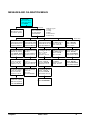
CHAPTER 7: MENU TREES........................................................................29
Measurements Menu........................................................................................................... 30
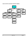
Messages and Calibrate Menus ........................................................................................ 31
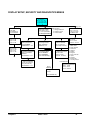
Analog Outputs, Setpoints and Relays Menus ................................................................ 32
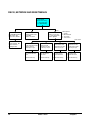
Display Setup, Security and Diagnostics Menus ............................................................ 33
RS232, Network and Reset Menus ................................................................................... 34
Tech Support, Set Hold Time and Other Menus ............................................................. 35
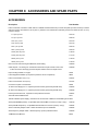
CHAPTER 8: ACCESSORIES & SPARE/REPLACEMENT PARTS.........36
CHAPTER 1: INTRODUCTION
See Instruction Manual 84372 supplied with the
instrument for standard operating information for the
770MAX. This service manual covers instrument
calibration, upgrades, RS232 communications and
other information for troubleshooting and training.
The 770MAX is provided with a Help key which
provides supplementary information about the area
of the menus being displayed. It can be especially
helpful in initial configuration.
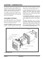
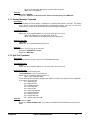
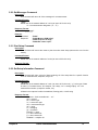
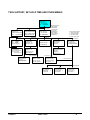
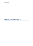
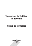
INSTRUMENT OVERVIEW
The 770MAX series utilizes 3 or 4 surface-mount
printed circuit boards plus a display module which
slide into the molded case and are held in place by
the front cover secured by two screws.
The main circuit board is located in the front of the
instrument. It contains the display module, main
processor, operating firmware and flash memory
which retains all setup configuration data plus
calibration data for (standard) analog outputs 1-4.
The power supply circuit board is located on the
left side of the instrument. It contains the universal
100-240 VAC power supply plus terminal
connections for the 4 standard analog outputs,
RS232 communications, discrete inputs and outputs
and pulse flow input circuits.
The measurement circuit board is on the right side
of the instrument and contains the measuring and
communication interface circuits for smart sensors
plus the NVRAM with measuring circuit calibration
data.
The options circuit board, if used, is in the center
and contains 4 relays, and may contain 4 additional
analog output circuits and their calibration data,
depending on the option specified. The label on the
rear of the case depends on which, if any, options
board is installed. An options board may be installed
in the field using the appropriate kit of parts.
770MAX exploded view
Chapter 1
Introduction
1
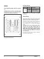
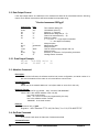
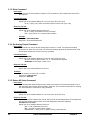
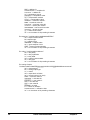
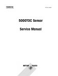
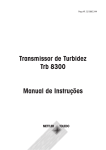
AC Power Wiring
WIRING
Board
For full installation wiring instructions, refer to
manual 84372. Information here is for reference
only.
CAUTION: Route all sensor and output signal
wiring away from power and switching circuits to
minimize noise pickup and interference.
Terminal
Connection
Earth ground
TB1
N
AC power, neutral
L
AC power, hot
CAUTION: Power wire insulation must be
stripped back 0.5 in. (13 mm) for reliable
connection.
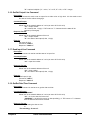
Sensor Wiring
Smart sensor patch cords plug into jacks CH1
through CH4. To avoid confusion when unplugged,
label the channel at the end of each patch cord.
Extending or making a break in patch cords must be
done only using extension cables 1005-87 (5 ft, 1.5
m) or 1015-87 (15 ft, 3 m) and union connector
25320.
CAUTION: Do not cut or shorten patch cords.
They use very fine gage shielded cable not
suitable for screw terminals or splicing. Do not
extend patch cords using computer network
cables since they provide only 8 of the 10
conductors needed by 770MAX and will damage
the modular jacks.
Pulse input flow sensor wiring is shown in Appendix
B of Instruction Manual 84372.
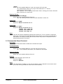
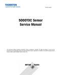
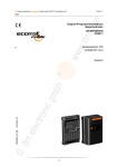
Rear panel terminal boards
2
Introduction
Chapter 1
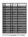
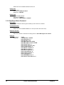
Other Connections
Board
Refer to rear panel figure for location.
Board
Terminal
Connection
1
Shield
2
Common
3
+5V
4
Discrete in 2
TB2
5
Discrete out 2
(All models)
6
Channel 6 flow
7
Channel 5 flow
8
Digital ground
9
RS232 receive
10
RS232 transmit
11
Shield
12
Common
13
Discrete in 1
14
Discrete out 1
TB3
15
Analog output 4 +
(All models)
16
Analog output 3 +
17
Analog output -
18
Analog output -
19
Analog output 2 +
20
Analog output 1 +
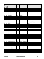
Board
Terminal
Connection
TB5
1
Relay 3, normally open
(Models
2
Relay 3, common
775-_ _1 &
3
Relay 3, normally closed
775-_ _2
4
Relay 4, normally open
only)
5
Relay 4, common
6
Relay 4, normally closed
TB6
7
Relay 1, normally open
(Models
8
Relay 1, common
775-_ _1 &
9
Relay 1, normally closed
775-_ _2
10
Relay 2, normally open
only)
11
Relay 2, common
12
Relay 2, normally closed
Connection
21
Shield
22
Not Used
23
Not Used
TB4
24
Analog output 5 +
(Model
25
Analog output 6 +
775-_ _2
26
Analog output -
only)
27
Analog output -
28
Analog output 7 +
29
Analog output 8 +
30
Shield
Chapter 1
Terminal
Introduction
3
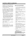
CHAPTER 2: METER CALIBRATION
The 770MAX has been factory calibrated to meet its
specifications. It is not normally necessary to recalibrate unless extreme conditions cause out-ofspec operation shown by verification. Periodic
verification or calibration may also be necessary to
conform with QC requirements.
VERIFICATION PROCEDURE
1.
If the 770MAX outputs are connected for alarm
or control, set a hold time per steps 3-6 of the
calibration procedure in the next section. Press
Menus twice to exit.
2.
Connect the appropriate adapter to the patch
cord of the channel to be verified.
3.
Connect the adapter leads to the test
equipment. (The resistance adapter has four
leads—two for resistance and two for
temperature.)
NOTE: This is an extensive process requiring 72
calibration points to fully cover all measurement
ranges of all parameters on all channels. It is
strongly recommended, where possible, to use
the Thornton 1875 Automatic Smart Calibrator Kit
which is supplied with a traceable certificate of
accuracy. It also enables printing out calibration
certificates for instruments it has calibrated. It is
supplied with its own instruction manual.
4.
On the 770MAX front panel, press Menus.
5.
Press the up arrow key until “Go to: Calibrate”
is displayed. Press Enter.
6.
Press the down arrow key to display “Go to:
Meter-Verify”.
7.
Press Enter. The channel, parameter and range
identification are displayed.
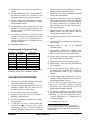
It is necessary to verify and/or calibrate only those
measuring circuits actually being used in the
installation. The following Adapters are needed to
interface with standards equipment:
8.
Select the channel and measurement type to be
verified
using
Enter
and
up
arrow.
i
(Measurement types are Res_ , Temp, Volts
and Freq.)
1000-82 resistance adapter
resistivity, temperature.
9.
Enter the verification value from Table A at
“Input:__ “, including any unit multiplier, e.g. K,
M, etc.
The 770MAX may be calibrated using high
precision resistance decade boxes, voltage source
and frequency generator with the following
procedures. This is intended only for installations
that have a policy of traceability to their own internal
standards. Standards equipment accuracies must
exceed the 770MAX specifications as required by
the applicable QC policy.
for
conductivity,
1000-79 voltage adapter for pH, ORP, pressure,
level.
1000-83 frequency adapter for flow.
Before attempting calibration, perform a verification
to determine if calibration is, in fact, necessary.
Verify at least one value for each internal range.
Recommended values are given in the table at the
end of the verification procedure.
10. Set the test equipment for exactly the same
verification value from Table A.
11. Allow the error value to fully stabilize and then
confirm that the resulting Error (in percent of
reading, except for voltage) is acceptable.
12. NOTE: Calibration is unnecessary if the error is
smaller than the limit of error of the standard or
of the 770MAX specification.
13. Press Enter to reach the parameter/range field,
e.g. Res #_.
14. Press up arrow to go to the next range and
repeat steps 8-12 for the 3 remaining resistance
verification points.
i
The meter will display Res #1, Res #2, Res #3, or Res
#4. This is to accommodate a future feature. All of these
selections are equivalent: the meter will auto-range to the
correct measuring circuit regardless of the number
indicated.
4
Meter Calibration
Chapter 2
15. Repeat steps 8-13 for the other channels to be
verified.
16. For the temperature range, repeat steps 2-14
but with the decade box connected to the
temperature leads of the conductivity adapter.
will be held at their current status for that period
of time to prevent upset while off-line.
7.
Press Enter. The channel, parameter and range
identification are displayed.
8.
Select the channel and range to be calibrated
using Enter and up arrow. Select the calibration
Type (number of points). It is recommended to
do 3-point calibrations for resistance and 2point calibrations for all other measurements,
including temperature.
9.
Press Page Down to display the CALIBRATE
METER screen with the reading and the
recommended calibration value.
17. For the voltage range, repeat steps 2-15 with a
precision voltage source connected to Smart
voltage adapter 1000-79.
18. For the frequency range, repeat steps 2-15 with
a precision frequency generator producing a 03 V square wave connected to Smart frequency
adapter 1000-83.
19. For frequency verification of channels 5 and 6,
connect the frequency generator directly to TB2
terminals 7 (+) and 6 (+) respectively and to
common, TB2 terminal 2 (-). Repeat step 18,
omitting the adapter.
20. Press Menus twice to exit.
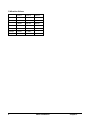
Parameter
Verification
Range of
& Range
Point
Measurement
Res 3*
100 Ω
0 – 700 Ω
Res 2*
2000 Ω
300 – 14,000 Ω
Res 1*
50,000 Ω
3750 – 175,000 Ω
Res 0*
1 MΩ
150,000 – 10 MΩ
Temp
1100 Ω
900 – 1500 Ω
Volts
0.5 V
-1.5 to +1.5 V
Freq
500 Hz
0.5 – 4000 Hz
*The 770MAX automatically selects the appropriate
measuring range for the resistance it detects.
CALIBRATION PROCEDURE
Connect the appropriate adapter to the patch
cord of the channel to be calibrated.
2.
Connect its leads to the test equipment. (The
resistance adapter has four leads—two for
resistance and two for temperature.)
3.
On the 770MAX front panel, press Menus.
4.
Press the up arrow key until “Go to Calibrate” is
displayed, then press Enter.
5.
Press the up arrow key to display “Go to: Meter”
and press Enter.
6.
In “Hold time= 00 mins”, if meter outputs are
connected for alarm or control, enter a value
greater than the time in minutes needed to
complete calibration. Analog and relay outputs
Chapter 2
11. Press Page Down and wait for the calibration to
be performed.
12. Repeat steps 10
calibration points.
Recommended Verification Points
1.
10. Set the test equipment for the exact calibration
ii
value.
and
11
for
additional
13. On completion, “METER CAL IS DONE” will be
displayed. Correct the date if necessary and
page up twice to the main calibration screen.
14. Set the channel, parameter, range and type for
the next calibration and page down.
15. Repeat steps 8-14 for the remaining ranges.
16. Repeat steps 1 and 8-15 for the other channels
to be calibrated.
17. For the temperature range, repeat steps 1-2
and 8-16 but with the decade box connected to
the temperature leads of the conductivity
adapter.
18. For the voltage range, repeat steps 1-2 and 816 with a precision voltage source connected to
Smart voltage adapter 1000-79.
19. For the frequency range, repeat steps 1-2 and
8-16 with a precision frequency generator
producing a 0-3 V square wave connected to
Smart frequency adapter 1000-83.
20. For frequency calibration of channels 5 and 6,
connect the frequency generator directly to TB2
terminals 7 (+) and 6 (+) respectively and to
common, TB2 terminal 2 (-). Repeat step 19,
omitting the adapter.
21. Press Menus twice to exit.
ii
Units manufactured prior to March 00, may give an
erroneous default resistance on one range of 2Ω which
should be changed in the display and in the decade box
setting to 200Ω.
Meter Calibration
5
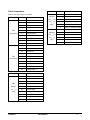
Calibration Values
Point 1
Point 2
Point 3
Res #1
4.000MΩ
160.0KΩ
1.8MΩ
Res #2
160.0KΩ
7000Ω
25.0KΩ
Res #3
7000Ω
500.0Ω
2000Ω
Res #4
500.0Ω
10.0Ω
200.0Ω
Temp
1000Ω
1400Ω
-
Voltage
1.000V
-1.000V
-
Freq.
100.0 Hz
1000.0 Hz
-
6
Meter Calibration
Chapter 2
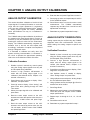
CHAPTER 3: ANALOG OUTPUT CALIBRATION
8.
Enter the date and press Page Down to save it.
ANALOG OUTPUT CALIBRATION
9.
Press page up twice and repeat steps 2 and 5-8
for the additional outputs.
This section describes calibration of the 0/4-20 mA
output signals. For startup information to scale the
range that the signal represents in engineering
units, see main Instruction Manual 84372, Chapter
4. Analog output signals are factory calibrated
within specifications but may be re-calibrated if
necessary.
10. Press Menus twice to exit and resume normal
measurement. The 770MAX automatically
computes any devi ation from 4 and 20 mA and
adjusts itself accordingly.
The 770MAX analog output calibration is performed
by measuring the output signal when it is set to its
minimum (4 mA) and maximum (20 mA) limits and
entering the exact mA value into the instrument’s
display. The 770MAX automatically computes any
deviation from 4 and 20 mA and adjusts itself
accordingly. Verification of outputs is accomplished
through a diagnostic menu.
ANALOG OUTPUT VERIFICATION
It is desirable to calibrate and verify when the
system receiving instrumentation is connected in
the circuit to present the approximate operating
load to the circuit. Maximum load is 500 ohms.
Calibration Procedure
1.
2.
Disable or place in manual any control system
using the analog output signals since they will
be interrupted during calibration.
Connect a high precision milli-ammeter in
series with the analog output signal to be
calibrated. (See Manual 84372, Chapter 4 for
terminal connections.)
3.
Press Menus and Up arrow to display “Goto:
Calibrate”, and press Enter.
4.
Press Up arrow to display, “Goto: Analog”, and
press Enter twice, passing through the Hold
Time screen.
5.
Select the output signal # to be calibrated and
press Enter.
6.
Read the exact output current on the milliammeter and enter that precise value into the 4
mA reads= 4.0000 screen and press Page
Down.
7.
Read the exact output current on the milliammeter and enter that precise value into the
“20 mA reads= 20.000” screen of the 770MAX
and press Page Down.
Chapter 3
11. Reactivate any system suspended in step 1.
Analog outputs may be verified using the 770MAX
diagnostic menu and a milli-ammeter. The menu
allows setting the analog outputs to specific mA
values.
Verification Procedure
1.
Disable or place in manual any control system
using the analog output signals since they will
be interrupted during verification.
2.
Connect a high precision milli-ammeter in
series with the analog output signal to be
verified. (See Manual 84372, Chapter 4 for
terminal connections.)
3.
Press Menus and Down arrow to display, “Goto:
Diagnostic” and press Enter.
4.
Use Up/down arrows if needed to display,
“Goto: Analog Output” and press Enter.
5.
Using up/down arrows select the Analog Output
# to be verified and press Enter.
6.
Using Up/down arrows set Output @ 4.00mA or
another level to be verified.
7.
Press Page Down.
8.
Measure the actual output on the milli-ammeter,
record the value and compare it with 770MAX
output specifications.
9.
Repeat steps 6 through 8 for 8, 12, 16 and
20mA.
10. Press Menus twice to exit
12. Reactivate any system suspended in step 1.
Analog Output Calibration
7
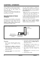
CHAPTER 4: UPGRADES
There is software for various functions located in
the 770MAX. The need for field upgrade is likely to
occur only with the Main Program and
Measurement software.
Optional relays and additional analog outputs can
be added in the field using the appropriate kits
described later in this chapter.
The main program software is changed by
downloading the new operating file using Thornton
utility program Max95.exe. It runs on computers
using Windows95 or later and occupies about 0.7
MB of hard disk space.
NOTE: Not all menus of the Max95 program are
functional—use only those needed for the
upgrade as described in the procedure below.
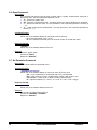
A cable is required with connector for the
computer’s RS232 port. Most computers use a DB9
connector as shown. Tinned leads at the other end
connect to the 770MAX screw terminals.
MAIN PROGRAM SOFTWARE
UPGRADE
Over the life of the instrument, it may become
desirable to upgrade the main operating software of
the 770MAX to a newer version. The main
operating software revision number can be
displayed by stepping through the menus: Other
Menus/Software Revs/Main Program.
Because the memory chip containing operating
software also contains extensive instrument
calibration data, it is not practical to upgrade
software by replacing the memory chip.
770MAX to computer RS232 port wiring
1
2
3
4
5
6
7
8
9
10
DB9 Connector to
computer (view of end 5
of cable that plugs into 9
computer)
2.
3.
8
Ground
Receive
Transmit
1
6
4.
From e-mail or floppy disk, copy the program
Max95.exe and the new 770MAX software file
e.g. 43714_14 into a convenient folder or
desktop of the computer.
5.
Run Max95.exe by double clicking it in
Windows Explorer and ignore any small
incidental windows that may open.
6.
Click to open ‘Communication’ menu and ‘RS232 Functions’ and select ‘Gateway Port
Setup’.
7.
Select Port—COM 1 (or other port if you are
using another).
8.
Select Baud Rate—38400.
Procedure
1.
770MAX
TB2 terminals
Record all the configuration settings and the
serial number of the 770MAX unit being
upgraded.
Confirm that the 770MAX is configured for
communications. Press Menus and up arrow to
display “RS232 Setup”. Set Baud = 38.4K, Par
= Even, Data Output = Off, if they are not
already set this way.
Connect the 770MAX to the computer RS232
port as shown above.
Upgrades
Chapter 4
9.
Select Data Bits—8.
must be done at an approved static free work
station. Personnel replacing static sensitive
devices should be properly grounded to avoid
component damage.
10. Select Parity—Even.
11. Uncheck Enable Polling. Leave other settings
as found (Flow Control—Xon/Xoff, Stop Bits—
1).
12. Click OK and observe ‘Connected’ in the lower
border of the window when communications are
functioning.
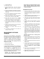
Installation Procedure
1.
Disconnect power wiring and unplug all input
and output connections from the unit, noting the
location of each plug-in connector for use in reinstallation.
2.
Loosen the two front cover screws—they are
captive and will be retained in the cover.
3.
Lift the front cover off the instrument and unplug
the keypad ribbon cable from the front circuit
board.
4.
Carefully slide the entire assembly of circuit
boards out of the case onto a static-free
surface.
5.
Unplug the measurement circuit board (rightmost board which has the 4 Smart sensor patch
cord sockets) from the front circuit board.
6.
Locate the part no. 43715 large integrated
circuit in a socket (position U6) of the
measurement circuit board. Note that the
sloped edge of the integrated circuit faces the
patch cord sockets. Using the PLCC diagonal
extraction tool or alternative tools noted above,
gently remove the integrated circuit from the
socket.
13. Click on the integrated circuit button (Program
th
Unit, 4 from right) on the tool bar.
14. Select Units to Program—One Unit and enter 0
(zero) in the box. Leave Unit Type at Main.
15. Click ‘Read’ and locate the new 770MAX
software file and click OK. The new software
version will be loaded into computer memory.
16. Click ‘Program’. Loading to the 770MAX will
take several minutes. Allow to run until 100% is
displayed.
17. Restore the serial number of the unit using the
appropriate command in Chapter 6.
18. Disconnect
770MAX.
the
RS-232
wiring
from
the
19. If necessary, reconfigure the unit with the
settings recorded in step 1.
MEASUREMENT SOFTWARE
UPGRADE
Over the life of the instrument, it may become
desirable to upgrade the measurement software of
the 770MAX to a newer revision to add additional
capabilities. 770MAX measurement software is
upgraded by installing a new part 43715 integrated
circuit in a socket located on the measurement
printed circuit board. The following tools and
equipment are needed:
1. Static-free work station.
2. Small flat-blade screwdriver.
3. PLCC diagonal extraction tool (to remove the
integrated circuit). Part number 126-453 available
from Contact East, Inc., 1-978-682-2000. (If the tool
is not available, the integrated circuit can be
removed using two very small screwdrivers and
prying at the diagonal corners of the chip. Use extra
care to prevent damage to the socket.)
CAUTION: Excessive force or twisting could
break the socket.
7.
Align the new integrated circuit over the socket
with the sloped edge facing the patch cord
sockets. Press it evenly into place with a thumb
or finger.
8.
Plug the measurement board back into the front
display board.
9.
Carefully align the entire circuit board assembly
so each circuit board keys into its respective
slot in the case and slide it in. Some flexing
may be necessary to assure complete
installation.
10. Plug the front cover keypad ribbon cable back
onto the display circuit board pins.
11. Replace the cover back onto the instrument and
tighten the two cover screws.
CAUTION: This instrument and associated
electronic parts are static sensitive. All work
Chapter 4
Upgrades
9
12. Reconnect input and output plugs in their
original locations and re-wire power to the
meter.
7.
Carefully align the entire circuit board assembly
so each circuit board keys into its respective
slot in the case and slide it in. Some flexing
may be necessary to assure complete
installation. The terminal blocks must fit into the
cutouts to be flush with the back of the case.
8.
Plug the front cover keypad ribbon cable back
onto the display circuit board pins.
9.
Replace the cover back onto the instrument and
tighten the two cover screws.
OUTPUT UPGRADES
Relays and additional analog outputs may be added
with circuit boards to an existing 775-_A0
Instrument (which has no option board already
installed). Kit 1000-91 adds 4 SPDT relays to
convert an instrument to model 775-_A1. Kit 100092 adds 4 SPDT relays and 4 additional analog
outputs, to convert an instrument to model 775-_A2.
These options are UL and cUL recognized when
installed in instruments manufactured since July
2000. These options are not CE rated.
CAUTION: Adding these
operating conditions:
outputs
restricts
10. Mark the instrument identification label with the
appropriate model number: replace the final “0”
in 775-_A0 with a “1” if using 1000-91 or with a
“2” if using 1000-92. Obliterate the CE mark
with a waterproof marker.
11. Reinstall in the existing wiring plugs to
respective receptacles and add connections to
the new outputs as required.
Kit 1000-91 lowers the maximum ambient
temperature rating to 104°F (40°C) when
operating on 230 VAC power.
Kit 1000-92 lowers the maximum ambient
temperature rating to 104°F (40°C) on 115 VAC
power and cannot be used above 130 VAC. This
kit may only be installed in an instrument with
main software revision 1.5 or higher.
Output Kit Installation Procedure
1.
Disconnect power wiring and unplug all input
and output connections from the unit, labeling
the location of each plug-in connector for use in
re-installation.
2.
Peel off the rear face terminal identification
label and replace it with the label supplied in the
kit which will have additional cutout(s).
3.
Loosen the two front cover screws—they are
captive and will be retained in the cover.
4.
Lift the front cover off the instrument and unplug
the keypad ribbon cable from the front circuit
board.
5.
Carefully slide the entire assembly of circuit
boards out of the case onto a static-free
surface.
6.
As shown in the exploded view in Chapter 1:
Introduction, align the new output option circuit
board with the large dual connector at the
bottom back, between the power supply and
measurement boards. Carefully plug it into the
back of the main circuit board.
10
Upgrades
Chapter 4
CHAPTER 5: TROUBLESHOOTING
ON-LINE ERROR MESSAGES
The following messages can appear in the “Go to:
Messages” menu to indicate error conditions or
problems with reading sensors. This menu area
should always be checked first when an operating
problem is encountered.
23. "Range may be wrong" – measurement may
have a wrong range (i.e. set for S/cm instead of
uS/cm).
24. "Invalid setpoint #"
25. "Reference volts bad" – for pressure sensors
this is a bad sensor.
26. "Flow rate is 0" – the flow rate is zero gpm so
the calculated measurement is zero or
overrange.
1.
"Measure PCB failed" – hardware failure.
2.
"No sensor on chan"
3.
"Invalid sensor type"
4.
"Sensor checksum err"
28. "A/D over range" – the A/D convert reported an
error, may be a defective measurement board.
5.
"Sensor const bad" – the sensor multiplier or
adder factor may be wrong.
29. "Unknown error #xxxx"
6.
"Invalid pipe ID"
7.
"Invalid tank height"
8.
"Invalid channel" – the selected channel is
wrong for the desired measurement (i.e
%Rejection, ratio, etc.).
9.
"Res sensor open" – patch cord or sensor cable
may be bad.
27. "Bad meter calibrate" – a meter calibration
factor is bad, should recalibrate.
10. "Res sensor shorted" – patch cord or sensor
cable may be bad.
11. "Compensate error" – wrong compensation
method selected or conductivity may be too
high for this compensation method.
12. "Temp out of range"
13. "Unable to measure R" – unable to measure
resistance of sensor (air bubble, dry cell, etc.).
14. "Invalid max PSI"
15. "Invalid tank area"
16. "Unknown measurement"
17. "Too big to display" – the measurement is too
large to be displayed.
18. "Total flow over" – total flow has reached the
upper limit.
20. "Voltage over range" – the voltage from the
sensor (pH, pressure) is too high (bad sensor).
22. "Check TDS factor"
Chapter 5
SENSOR TROUBLESHOOTING
Temp. Compensated Measurements
Temperature compensated measurements such as
conductivity/resistivity
and
pH
require
the
temperature signal from the sensor to be within
range or the compensated measurement will
display asterisks. If the temperature signal has
failed or is not available, operation can be
continued by changing the temperature source
(under the Measurements menu) to a fixed value or
to use the temperature signal from another channel
that is also correct for this measurement. In some
cases, using temperature from another channel
may be desirable anyway, to obtain a faster
responding or more accurate temperature signal.
“Raw” Sensor Signals
19. "Temperature high"
21. "Invalid max GPM"
“LSC is Locked” could appear in the startup screen
and indicates that internal local serial channel
communication has halted. This could be caused by
loose internal connections. Re-seat all circuit board
and ribbon cable connectors and re-power the
instrument. If the message persists, factory service
will be required.
Direct reading of the sensor output is available from
the “Measurements” menu. It gives “raw” readings
in base units, e.g. Hz for flowrate. It is not adjusted
with calibration factors, temperature compensation,
Troubleshooting
11
etc. and is helpful in finding the cause of erroneous
readings.
To view the “raw” reading, press Menus and select
the desired measurement. Page down to the last
normal screen (indicated by disappearance of the
down arrow in the lower right corner), then page
down one more to see “Raw reading from the
sensor= XXXXX XX” plus identification of channel
(and internal range for resistivity).
OFF-LINE DIAGNOSTICS
Select an output to test, then enter a current value
(milliamps) to send out the analog output then press
Page Down to set. Repeat test with a second
current value to verify range response.
Serial Port
On back of meter, use a jumper wire to connect
TB2 terminals 9 and 10 then press Enter to begin
test.
Network
The Diagnostic Menu is used to run a series of offline automated diagnostic testing routines to verify
the operation of system components, including:
meter, sensors, analog output, serial port, network,
display, keypad, flow channels, inputs and outputs.
NOTE: Some diagnostic tests may interrupt normal
operation (such as analog outputs).
Diagnostic not currently available.
Display
An automated sequence will test the display of all
characters (alpha, numeric and symbol). Press
Enter to stop the test.
To access the Diagnostic Menu:
Keypad
1.
Press Menus.
2.
Press the up arrow key until the Diagnostic
Menu is displayed, then press Enter.
3.
Use the up/down arrow keys to select a test,
then press Enter. The indicated test will be
performed and the results displayed.
4.
To test another component, press Page Up to
return to the Diagnostic Menu and select the
next component.
5.
After completing the desired diagnostics, press
Menus twice to exit the menu system and
return to display mode.
Press any key to test its response, the correct name
of the key should be displayed. Press Menus twice
to exit this test.
Flow Channels
Diagnostic not currently available.
Inputs
See the appropriate section below for information
regarding the specific diagnostic tests.
The level of the input lines (high or low) will be
displayed and updated every second.
Meter Tests
Outputs
Use to test the timers, ROM checksum, and RAM.
Tests are performed sequentially, press Enter to
perform next test.
Set the outputs low or high for testing. Press 1 to
set low or 2 to set high.
Self Tests
Smart Sensors
Select a channel to view the raw sensor data
(actual voltage, ohms, etc.).
Analog Output
12
An automated series of tests will check the
operation of the following components:
•
•
•
•
Smart sensors
Analog outputs
Discrete outputs
Discrete Inputs
Troubleshooting
Chapter 5
•
•
•
•
•
Network
Display circuit board
Measurement circuit board
Options circuit board
Other circuits (ROM, RAM, etc.)
The display shows how many tests have run, the
elapsed time and the number of errors found. Press
Menus to stop the test sequence.
Chapter 5
Troubleshooting
13
CHAPTER 6: RS232 COMMUNICATIONS
Connections for the RS232 serial port are shown in Chapter 4.
1. SERIAL PORT COMMUNICATIONS
1.1. General
The Serial Port Communications command set provides the user with complete control and configuration
of a meter.
All messages sent to and from the meter will consist of the printable set of ASCII characters.
Each message will be terminated with a carriage-return (<cr>) character.
All messages sent to the 770Max will receive a response. The response will consist of the
requested data, an "OK" message, or an error message.
All commands must specify an identifier address (same as the network address). A command
with an address different from that of the unit will be sent over the network. The identifier
address “00” can be used to indicate that the command is designated for the device on the
RS232 port (not another unit on the network).
NOTE: References to a network address are for future capability.
All floating point values use Intel standard format.
1.2. Command Format
The format of all commands is: "axxc…c<cr>".
Where:
"a" is the opcode (upper case letter from A to Z).
"xx" is the network address of the unit (from 00 to FF hexadecimal). This address can be
specified as "00" which indicates the command is for this unit (on the serial port).
"c…c" is the command data.
<cr> is the ASCII carriage-return character.
1.3. Response Format
The format of all responses is: "axx=c…c<cr>".
Where:
"a" is the opcode (upper case letter from A to Z).
"xx" is the network address of the unit (from 01 to FF hexadecimal).
"c…c" is the response data.
<cr> is the ASCII carriage-return character.
The response data will be one of the following types:
1. Command Accepted: if the command is accepted then the response data section will
consist of the message "OK".
2. Command Data: if the command requests data then that information will be returned. The
format of the data depends upon the command type.
3. Command Rejected: if the command is rejected then an error message will be returned with
the format: "ERROR #yy" where "yy" is an error code.
14
RS232 Communications
Chapter 6
1.4. Error Codes
The following error codes will be used when a command is rejected (the format is "ERROR
#xx"):
01: invalid opcode.
02: parameter error.
03: checksum error.
04: parity error.
05: unit is not available.
06: command failed.
07: timeout error.
0E: data not available.
2. COMMAND SET
2.1. Command Summary
1.
2.
3.
4.
5.
6.
7.
8.
9.
10.
11.
12.
13.
14.
15.
16.
17.
18.
19.
Command
Attention
Set Auto Data Output
Get Data
Reset
Set Parameter
Get Parameter
Key Press
Display Message
Self Test
Echo Command
Set Analog Output
Return All Setup
Get/Set Output Line
Read Input Line
Get/Set Date/Time
Print Meter Setup
Print Error Status
Get Messages
Get Setup Information
Function
Opcode
Returns the software revision level and serial number.
A
Enables or disables the data output
B
Returns the latest set of measurement data
D
Performs various types of resets (use with caution)
R
Sets a parameter value
S
Gets a parameter value
G
Simulates a key press, returns the menus displayed
K
Displays a message
M
Performs all of the self tests
U
Echos the characters in the command (for testing the port)
E
Sets the analog output current to a level (for testing)
O
Returns all setup information
Z
Gets or sets the state of an output line
L
Reads the state of an input line
I
Gets or sets the date or time
T
Sends the meter setup out serial port (readable format).
H
Returns a summary of all error counters
Q
Returns all messages for a measurement
F
Returns a block of data for measurements, or relays, etc.
V
All other opcodes will return an error message.
Chapter 6
RS232 Communications
15
2.2. Data Output Format
If the data output feature is enabled then the measurement data will be transmitted with the following
format. Each defined measurement will be transmitted as a separate string,
"Daa=bcd eeeeeeee fffffff ggh"
Position Field
01:
02-03:
04:
05:
06:
07:
Data
"D"
"aa"
"="
"b"
“c”
"d"
08:
09-17:
18:
19-24:
25:
26-27:
28:
""
"eeeeeeee"
""
"fffffff"
""
"gg"
“h”
This character always "D".
Unit address (00 to FF).
Always a "=" character.
Measurement designator (A .. Z).
Channel of measurement (1 – 6).
Setpoint condition.
(" " = no error, ">" = high setpoint exceeded,
"<" = low setpoint exceeded).
Always a space.
Measurement data
Always a space.
Units for measurement (example: Mo-cm).
Always a space.
Exclusive -or checksum of all preceding characters.
Carriage-Return character.
2.2.1. Data Output Example
D07=A1
286.2020 uS/cm
D07=B1
22.8267 oC
1C
03
2.3. Attention Command
Description:
This command will return the software revision level, meter configuration, and serial number. It is
also used to determine if the meter is on line and able to communicate.
Command Format:
"Axx"
Where "xx" is the network address of a unit (leave blank or set to 00 for this unit).
Response Format:
"Axx=Thornton #775-yyy (aaaaa….aaa), Ver=zzzz, S/N=bbbbbbbb”.
Where "xx" is the network address of the unit (00).
“yyy’ is the model number
“aaaa….aa” is the unit name (as programmed by the user).
“zzz” is the software revision number.
“bbbbbbbb” is the serial number
Example
Command: "A" or "A00"
Response: “A00=Thornton #775-LA0 (Lab Unit), Ver=1.00, S/N=000072358”.
2.4. Get Data Command
Description:
This command will return the latest set of measurement data.
Command Format:
16
RS232 Communications
Chapter 6
"Dxxab"
Where "xx" is the network address of a unit (can be set to 00 for this unit).
"a" = measurement channel (A..Z) to get. If this character is a "?" then all
measurements will be returned.
"b" = optional = "F" to request measurement data in floating point format, otherwise
data is returned in the real format.
Response Format:
"Dxx=bcd eeeeee ffffff ggf"
Where "xx" is the network address of the unit.
"bc….ff" is the data returned with the format described in section 2.2.
Example #1:
Command: "D00B"
Response: "D00=A1 513.67 Ko-cm C7"
Example #2:
Command: "D00?"
Response: "D00=A1 513.67 Ko-cm C7"
"D00=B1 25.45 DegF DA"
"D00=C2 18.18 Mo-cm 32"
"D00=D2 25.45 DegC 91"
Notes:
If the all of the data is requested by specifying the channel as "?" then a number of responses
will be sent out with the format described above. Each response or line will be terminated with a
CR character. For example, sending the command "D00?" may result in 8 responses for the 8
defined measurements in the meter.
2.5. Set Auto Data Output Command
Description:
This command will enable or disable the automatic data output.
Command Format:
"Bxxa"
Where "xx" is the network address of a unit (can set to 00 for this unit).
"a" = " 1" to enable the data output, "0" to disable the data output.
Response Format:
"Bxx=OK"
Where "xx" is the network address of the unit.
Example
To enable the data output of this unit:
Command: "B001"
Response: "B00=OK"
Notes:
If the data output is enabled on a unit over the network, then the data will be sent out the serial
port of that unit only (the data will not be sent over the network).
Chapter 6
RS232 Communications
17
2.6. Reset Command
Description:
This command will perform various types of resets: either a system, measurement, total flow or
total grains reset. The reset parameter character can be:
1. "S" - performs a system reset.
2. "M" - performs a measurement reset. Averaging buffers are cleared. RTDs are re-measured.
3. "T" - performs a total flow reset. The next character in the command specifies the channel (A
… P).
4. “G” – resets a total grains measurement. The next character in the command specifies the
channel (A ... P)
Command Format:
"Rxx*ab"
Where "xx" is the network address of a unit (set to 00 for this unit).
"a" is reset type (either S, M, T, or Z).
"b" is the optional information (such as channel number for a total flow reset).
Response Format:
"Rxx=OK".
Where "xx" is the network address of the unit.
Example:
Perform a system reset.
Command: "R00*S"
Response: "R00=OK"
2.7. Set Parameter Command
Description:
This command will set a parameter value.
Command Format:
"Sxxaabb=ccccccccccd"
Where "xx" is the network address of a unit (can set to 00 for this unit).
"aa" = code of parameter to be changed (00 to FF), see list below.
"bb" = index number (channel , measurement number, relay number, etc).
"cccccccccc" = value (up to 10 digits including a decimal point).
"d" = optional multiplier ("u" = micro, "m" = milli, "K" = kilo, or "M" = mega).
Response Format:
"Sxx=OK".
Where "xx" is the network address of the unit.
Example:
Set the value of setpoint #2 to 0.001125.
Command: "S002A02= 1.125000m".
Response: "S00=OK".
18
RS232 Communications
Chapter 6
2.8. Get Parameter Command
Description:
This command will get a parameter value.
Command Format:
"Gxxaabb?"
Where "xx" is the network address of a unit (can set to 00 for this unit).
"aa" = code of parameter to be changed (00 to FF), see list below.
"bb" = channel or measurement number (index number).
Response Format:
"Gxxaabb=ccccccccccd ".
Where "xx" is the network address of the unit.
"aa" = code of parameter to be changed (00 to FF), see list below.
"bb" = index number (channel , measurement number, relay number, etc).
"cccccccccc" = value (up to 10 digits including a decimal point).
"d" = optional multiplier ("u" = micro, "m" = milli, "K" = kilo, or "M" = mega).
Example:
Get the value of setpoint.
Command: "G002A02?".
Response: "G002A02=1.1125000m".
2.9. Variables For Get and Set Parameter Command
For the index number, the maximum value depends upon the parameter type and may be:
1. #Channels
=6
2. #Circuits
=7
3. #Measurements
= 16
4. #Analog outputs
=8
5. #Relays
=4
6. #Setpoints
= 16
7. #Discrete Outputs = 2
8. #Discrete Inputs
=2
Chapter 6
RS232 Communications
19
Int. Code
Hex
Code
Name
01
02
03
04
05
06
07
08
09
10
11
12
13
14
15
16
17
18
19
20
21
22
23
24
25
26
27
28
29
30
31
32
33
34
35
36
37
38
39
40
41
42
43
44
45
46
47
48
49
50
01
02
03
04
05
06
07
08
09
0A
0B
0C
0D
0E
0F
10
11
12
13
14
15
16
17
18
19
1A
1B
1C
1D
1E
1F
20
21
22
23
24
25
26
27
28
29
2A
2B
2C
2D
2E
2F
30
31
32
SmasterPassword
sUser1Password
sUser2Password
SCustomerName
ISensorType
ISensorSpecifics
IMeasureChan
IMode
IRange
iOtherChan1
iOtherChan2
lMeasureErrorCode
sName
iAvgMode
fCellMultiplier1
fCellAdditive1
fCellMultiplier2
fCellAdditive2
fTDSFactor
iCompMode
fLinearComp
iTempSource
fManualTemp
iResolution
lSerialNumber
lSensorCalDate
dTotalFlow
fPipeID
iFlowExternReset
fMaxGPM
fMaxPSI
fTankHeight
fTankArea
fIP
fSTC
fCellMultiplier3
fCellAdditive3
fInstallationK
iSpMeasurement
iSpType
iSpRelay
fSpValue
iSpMult
iSpIgnorOver
lSPTimer
iRDelay
iRHyster
iRState
iExternReset
iRType
20
Type
Max Index Number
Description
String
String
String
String
Integer
Integer
Integer
Integer
Integer
Integer
Integer
Integer
String
Integer
Float
Float
Float
Float
Float
Integer
Float
Integer
Float
Integer
Long
Long
Float
Float
Integer
Float
Float
Float
Float
Float
Float
Float
Float
Float
Integer
Integer
Integer
Float
Integer
Integer
Long
Integer
Integer
Integer
Integer
Integer
1
1
1
1
#Channels
#Channels
#Measurements
#Measurements
#Measurements
#Measurements
#Measurements
#Measurements
#Measurements
#Measurements
#Channels
#Channels
#Channels
#Channels
#Measurements
#Measurements
#Measurements
#Measurements
#Channels
#Measurements
#Channels
#Channels
#Channels
#Channels
#Channels
#Channels
#Channels
#Channels
#Channels
#Channels
#Channels
#Channels
#Channels
#Channels
#Setpoints
#Setpoints
#Setpoints
#Setpoints
#Setpoints
#Setpoints
#Setpoints
#Relays
#Relays
#Relays
#Relays
#Relays
Master password
User #1 password
User #2 password
Name of unit
Sensor type
Sensor sub-type (signal)
Measurement channel
Measurement mode
Measurement range
st
1 other channel needed for measure
nd
2 other channel needed
Measurement error codes
Name of measurement
Averaging level
Sensor Multiplier for main signal
Sensor additive for main signal
Sensor multiplier for second signal
Sensor additive for second signal
TDS factor
Compensation method
Linear compensation value
Temperature source
Fixed temperature value
Resolution for measurement
Sensor serial number
Sensor calibration date/time
Total flow for channel
Pipe inside diameter
External flow reset enabled/disable
Maximum GPM
Maximum PSI
Tank height in feet
Tank area in square feet
IP factor for pH
STC factor for pH
nd
2 sensor multiplier for Inductive
nd
2 sensor additive for Inductive
For inductive sensors
Measurement for setpoint
Type of setpoint
Relay or output for setpoint
Setpoint value
Multiplier factor for setpoint
Ignore overrange for setpoint
Time since last setpoint error
Relay delay
Relay hysteresis
Relay state
Reset relay externally via input line
Type of relay
RS232 Communications
Chapter 6
Int. Code
Hex
Code
Name
51
52
53
54
55
56
57
58
59
60
61
62
63
64
65
66
67
68
69
70
71
72
73
74
75
76
77
78
79
80
81
82
83
84
85
86
87
88
89
90
91
92
93
94
95
96
97
98
99
100
101
33
34
35
36
37
38
39
3A
3B
3C
3D
3E
3F
40
41
42
43
44
45
46
47
48
49
4A
4B
4C
4D
4E
4F
50
51
52
53
54
55
56
57
58
59
5A
5B
5C
5D
5E
5F
60
61
62
63
64
65
iAoutSignal
iAoutType
iAoutLowEnd
iAoutControl
iAoutOnFailure
fAoutMin1
fAoutMid1
fAoutMax1
fAoutMin2
fAoutMax2
iAMin1Mult
iAMid1Mult
iAMax1Mult
iAMin2Mult
iAMax2Mult
iLanguage
iBaud
iParity
iDataOutputOn
iOutputTime
iNetworkAddress
iNetworkType
iAutoScrollOn
iDisplayMode
iDisplayStart
IDisplayOrder
bLockoutEnabled
iUser1LockState
iUser2LockState
fMeterCalSlope2
fMeterCalSlope1
fMeterCalOffset
lMeterVerDate
lMeterVerDate
dCalMeasureLimit
dCalMeasureBefore1
dCalMeasureAfter1
dCalMeasureBefore2
dCalMeasureAfter2
dCalMeasureBefore3
dCalMeasureAfter3
dCalValue1
dCalValue2
dCalVallue3
dCalVerifyInput1
dCalVerifyInput2
dCalVerifyInput3
fMeterCalSlope1Prev
fMeterCalSlope2Prev
fMeterCalOffsetPrev
iPowerSave
Chapter 6
Type
Max Index Number
Description
Integer
Integer
Integer
Integer
Integer
Float
Float
Float
Float
Float
Integer
Integer
Integer
Integer
Integer
Integer
Integer
Integer
Integer
Integer
Integer
Integer
Integer
Integer
Integer
Integer
Integer
Integer
Integer
Float
Float
Long
Long
Long
Float
Float
Float
Float
Float
Float
Float
Float
Float
Float
Float
Float
Float
Float
Float
Float
Integer
#Analogs
#Analogs
#Analogs
#Analogs
#Analogs
#Analogs
#Analogs
#Analogs
#Analogs
#Analogs
#Analogs
#Analogs
#Analogs
#Analogs
#Analogs
1
1
1
1
1
1
1
1
1
1
#Measurements
1
1
1
#Circuits * #Channels
#Circuits * #Channels
#Circuits * #Channels
#Circuits * #Channels
#Circuits * #Channels
#Circuits * #Channels
#Circuits * #Channels
#Circuits * #Channels
#Circuits * #Channels
#Circuits * #Channels
#Circuits * #Channels
#Circuits * #Channels
#Circuits * #Channels
#Circuits * #Channels
#Circuits * #Channels
#Circuits * #Channels
#Circuits * #Channels
#Circuits * #Channels
#Circuits * #Channels
#Circuits * #Channels
#Circuits * #Channels
1
Measurement for analog output
Analog output type
Low end either 0 or 4 mA
Output line to control for dual range
Output current on error or failure
RS232 Communications
Language (0=English).
Baud rate
Parity
Set to 1; Off, set to 0
Data output time in seconds
21
Int. Code
Hex
Code
Name
102
103
104
105
106
107
108
109
66
67
68
69
6A
6B
6C
6D
dTotalppmG
sUnitSerialNumber
dCell_K_Factor
dCell_F_Factor
lMDateTime
dCalVerifyMeasured1
dCalVerifyMeasured2
dCalVerifyMeasured3
Setpoint Types:
0
No Setpoint
1
High
2
Low
3
USP
4
Reset
Type
Max Index Number
Float
String
Float
Float
Long
Float
Float
Float
#Channels
1
#Channels*10
#Channels*10
1
#Circuits * #Channels
#Circuits * #Channels
#Circuits * #Channels
Analog
0
1
2
3
Description
K factors for Vortex flow sensors
F factors for Vortex flow sensors
Meter date/time in seconds since 1/1/98
Output Types:
Normal
Bilinear
Auto range
Log
2.10. Keypress Command
Description:
This command is used to simulate a key press from the front panel. The response is a string of
characters which is the message displayed as a result of the key press. Also, the cursor position
is returned.
Command Format:
"Kxxaa"
Where "xx" is the network address of a unit (can set to 00 for this unit).
"aa" is the key code as follows:
00 = Key #0.
01 = Key #1
02 = Key #2
03 = Key #3
04 = Key #4
05 = Key #5
06 = Key #6
07 = Key #7
08 = Key #8
09 = Key #9
0A = Menus key.
0B = Help key.
0C= Right Arrow key.
0D = Left Arrow key.
0E = Up Arrow key.
0F = Down Arrow key.
10 = Help key.
11 = Page-Up key.
12 = Page-Down key.
13 = Next key.
14 - Decimal/minus Key
FF = special code to make the unit exit the menu mode.
All other codes are not used.
Response Format:
If the key code is valid then the display message will be returned as:
"Kxx=a…a:bb".
Where "xx" is the network address of the unit.
22
RS232 Communications
Chapter 6
"a…a" is the message displayed as a result of the key press.
"bb" is the cursor position.
Example:
Command: "K000A"
Response: "K00=This is the main menu. Select a function then press NEXT:64"
2.11. Display Message Command
Description:
This command is used to display a message for a specified time period in seconds. The display
time is from 0 to 256 seconds (specified as a hexadecimal number). If the unit is in the menu
mode then the menus will be terminated before the message is displayed.
Command Format:
"Mxxaab...ba".
Where "xx" is the network address of a unit (can set to 00 for this unit).
"aa" is the display time in seconds (from 00 to FF).
"b..b" is the message to be displayed (up to 80 characters).
Response Format:
"Mxx=OK".
Where "xx" is the network address of the unit.
Example:
Display "This is a test" for 10 seconds.
Command: "M000AThis is a test".
Response: "M00=OK".
2.12. Self-Test Command
Description:
This command is used to perform the self-test/diagnostic test.
Command Format:
"Uxx*".
Where "xx" is the network address of a unit (can set to 00 for this unit).
Response Format:
"Uxx=OK" if all of the tests pass.
"Uxx=FAILED=aa" if one or more tests fail.
Where "xx" is the network address of the unit.
"aa" = code of test that failed.
If more than one test fails then multiple codes will be included in this response, each separated
by a comma. The codes are:
01 = ROM test fails.
02 = RAM test fails.
03 = NVRAM test fails.
04 = Timer test fails.
05 = A/D test fails.
06 = Serial port test fails.
07 = Network Test fails.
08 = Display test fails.
09 = Keypad test fails.
0A = Analog output test fails.
Example:
Command: "U00*"
Response: "U00=FAILED=01,04". This response indicates that the ROM test and timer tests
failed.
Chapter 6
RS232 Communications
23
2.13. Echo Command
Description:
This command is used to test the serial port. The characters in the command are sent back in
the response.
Command Format:
"Exxa…a"
Where "xx" is the network address of a unit (can set to 00 for this unit).
"a…a" = string of any ASCII characters used to test the port (up to 128).
Response Format:
"Exx=a…a=zz"
Where "xx" is the network address of the unit.
"a…a" = string of characters from the command.
"zz" = "OK" if there is no communication problem.
Example
Command: "E00123456789A"
Response: "E=00123456789A=OK"
2.14. Set Analog Output Command
Description:
This command is used to set the analog output current to a value. It is intended for testing
purposes only. When this command is received the analog outputs will be held at the set value
until another command is received or a key is pressed.
Command Format:
"Oxxa=bbbbbbbb"
Where "xx" is the network address of a unit (can set to 00 for this unit).
"a" is the analog output number (1-4, or 1-8 with optional outputs).
"bbbbbbbb" is the output current in mA.
Response Format:
"Oxx=OK".
Where "xx" is the network address of the unit.
Example:
Set the output of channel 3 to 12.125mA:
Command: "O00=312.125"
Response: "O00=OK"
2.15. Return All Setup Command
Description:
This command will cause the entire meter setup to be returned. Each setup parameter is sent
with the same format as the "Get Parameter" command. This command is equivalent to sending
the "Get Parameter" command for every parameter.
Command Format:
"Zxx*"
Where "xx" is the network address of a unit (can set to 00 for this unit).
Response Format:
The response will be multiple lines of data. Each line will be terminated with a CR character and
will have the following format (same as the Get Parameter Command response):
Gxxaabb=ccccccccccd".
Where "xx" is the network address of the unit.
"aa" = code of parameter (00 to FF).
"bb" = channel or measurement number.
"cccccccccc" = value (up to 10 digits including a decimal point).
24
RS232 Communications
Chapter 6
"d" = optional multiplier ("u" = micro, "m" = milli, "K" = kilo, or "M" = mega).
2.16. Get/Set Output Line Command
Description:
This command is used to set an output line to either a low or high level. It is also used to read
the state of the line without changing it.
Command Format:
"Lxxaab".
Where "xx" is the network address of a unit (can set to 00 for this unit).
“aa” = output number.
“b” = state (0=low, 1=high). If "b" is set to a "?" character then the state will be
returned (not changed).
Response Format:
"Lxxaa=b".
Where "xx" is the network address of the unit.
“aa” = output number.
"b" = the state of the output (0=low, 1=high).
Example:
Set output #1 high:
Command: "L00011"
Response: "L0001=1"
2.17. Read Input Line Command
Description:
This command is used to read the state of an input line.
Command Format:
"Ixxaa?".
Where "xx" is the network address of a unit (can set to 00 for this unit).
“aa” = input line number.
Response Format:
"Ixxaa=b".
Where "xx" is the network address of the unit.
“aa” = input number.
"b" = the state of the output (0=low, 1=high).
Example:
Read input #1 high:
Command: "I0001?"
Response: "I0001=1"
2.18. Get/Set Date/Time Command
Description:
This command is used to set or get the date and time.
Command Format:
"Txxaa=bbbbbbbb".
Where "xx" is the network address of a unit (can set to 00 for this unit).
“aa” = 01 for the date, 02 for the time.
“bbbbbbbb” = the time (hh:mm:ss) or date (mm/dd/yy). If "b" is set to a "?" character
then the date and time will be returned.
Response Format:
“Txx=OK” if setting the date or time
or
"Txx=mm/dd/yy, hh:mm:ss".
Chapter 6
RS232 Communications
25
Where "xx" is the network address of the unit.
Example #1:
Set the time:
Command: "T0002=13:45:00"
Response: "T00=OK"
Example #2:
Read the data and time:
Command: "T0000=?"
Response: "T00=07/02/97, 13:45:20"
2.19. Print Error Status Command
Description:
This command is used to get a summary of all of the error counters
Command Format:
"Qxx".
Where "xx" is the network address of a unit (can set to 00 for this unit).
Response Format:
“aaaaaaa….”
Each error counter is returned as a string such as “Qxx =Messages sent: 45781”.
Example:
Command:
Response:
26
"Q3A".
T3A=08/31/98, 10:54:59
Q3A =Exceptions: 0.
Q3A =Divide by 0: 0.
Q3A =Messages sent: 45781.
Q3A =Messages received: 43259.
Q3A =Comm errors: 1.
Q3A =Comm timeouts: 2517.
Q3A =LSC Bus Busy: 2.
Q3A =Buffer overflows: 0.
Q3A =Wrong sender: 0.
Q3A =Error responses: 0.
Q3A =LSC Collisions: 0.
Q3A =LSC Tx Timouts: 0.
Q3A =LSC Resets: 0.
Q3A =EEPROM Errors: 0.
Q3A =Sensor Nvram Errors: 0.
RS232 Communications
Chapter 6
2.20. Get Messages Command
Description:
This command will return all of the messages for a measurement.
Command Format:
"Fxxa".
Where "xx" is the network address of a unit (can set to 00 for this unit).
“a” = the measurement designator (“A” – “P”).
Response Format:
“Fxx=yyyyyyyyy”.
Example:
Command:
Response:
“F3AA".
“F3AA=Measure PCB failed.”
“F3AA=Temp out of range. ”
“F3AA=Res sensor open.”
2.21. Print Setup Command
Description:
This command will instruct the meter to print the entire meter setup (same as the one from the
menus).
Command Format:
"Hxx*".
Where "xx" is the network address of a unit (can set to 00 for this unit).
Response Format:
“aaaaaaa….”
2.22. Get Setup Information Command
Description:
This command will return a block of data containing all of the setup data for a specific function
such as measurements, setpoints, relays, etc.
Command Format:
"Vxxyyzz*".
Where "xx" is the network address of a unit (can set to 00 for this unit), “yy” is the type of data
to return (“01”=measurement, “02”=setpoint, “03”=relays, “04” = analog output), “zz” = the
measurement number (or setpoint number, etc).
All data in the response is either hexadecimal, floating point, or ascii string.
Response Format:
For measurement: “Vxx01zz=aabbccdd ….zz”
“aa” = channel.
“bb” = sensor type.
“cc” = sensor sub type.
“dd” = measurement type.
“ee” = range.
“ff” = averaging.
“gf” = resolution.
“hhhhhhh” = name.
“ii” = other channel #1.
“jj” = other channel #2.
“kkkkkkkk” = multiplier #1.
Chapter 6
RS232 Communications
27
“llllllll” = additive #1.
“mmmmmmmm” = multiplier #2.
“nnnnnnnn” = additive #2.
“oo” = temperature source.
“pppppppp” = temperature value.
“qq” = compensation method.
“rrrrrrrr” = compensation value.
“ssssssss” = maximum value #1.
“tttttttt” = maximum value #2.
“uuuuuuuu” – maximum value #3.
“vvvvvvvv” = sensor part number.
“wwwwwwww” = sensor serial number.
“xxxxxxxx” = sensor cal data.
“yy” = smart sensor status.
“zz” = xor checksum of all preceding characters
For setpoints: “Vxx02zz=aabbccddddddddeeffffffffzz”
“aa” = setpoint measurement
“bb”=setpoint type.
“cc” = setpoint relay
“dddddddd” = setpoint value.
“ee” = ignore setpoint if error
“ffffffff” = time since last activation
“zz” = xor checksum of all preceding characters
For relays: “Vxx03zz=aabbccddeezz”
“aa” = relay delay
“bb” = relay hysteresis.
“cc” = relay state.
“dd” = external reset enabled.
“ee” = relay type.
“zz” = xor checksum of all preceding characters
For Analog Outputs:
“Vxx04zz=aabbccddeeffffffffgggggggghhhhhhhhiiiiiiiijjjjjjjjkkkkkkkkllmmmmmmmz”
“aa” = measurement.
“bb” = analog output type.
“cc” = control
“dd” = output level on failure.
“ee” = low end ouput (0 or 4mA)
“ffffffff” = minimum value #1
“gggggggg” = mid value #1
“hhhhhhhh” = max value #1
“iiiiiiii” = min value #2
“jjjjjjjj” = max value #2
“kkkkkkkk” not used.
“ll” = number of decades.
“mmmmmmmm” = calibration date.
“zz” = xor checksum of all preceding characters
28
RS232 Communications
Chapter 6
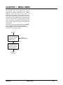
CHAPTER 7: MENU TREES
The following menu trees illustrate the general
sequence of settings available in the 770MAX.
However, some low level menu items are
dependent on the type of sensor connected and on
previous menu selections. For example, only a flow
measurement with totalized flow units selected will
show the menu field for setting External Reset.
Also, the model of 770MAX will determine how
many analog outputs and relays are present for
configuration.
The screens below will appear after pressing Menu
only if security has been enabled. Otherwise
pressing Menu accesses the Main Menu directly,
as shown on the following pages.
Menu key
ENTER PASSWORD
A password is needed
to enter the menus.
Password =*****
MAIN MENU
Normal operation
Wrong Password
ENTER PASSWORD
Invalid password, You
can view menus only.
Press Enter if OK.
Enter key
MAIN MENU
View Only
Chapter 7
Menu Trees
29
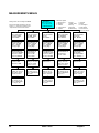
MEASUREMENTS MENUS
MAIN MENU
Select a menu using
↑,↓ then press Enter
Go to: Measurements
Settings which can be changed are inBold.
Some menu displays depend on previous
settings, e.g. 'Fixed Temp' appears only if
'Temp Source' has been set to 'Fixed'.
Conductivity Sensor
pH/ORP Sensor
6. Relays
7. Display Setup
8. Security
9. Diagnostic
10.RS232 Setup
Pressure Sensor
11. Network
12. Reset
13. Tech Support
14. Other Menus
15. Set Hold Time
Tank Level Sensor
MEASUREMENT: A
Sensor input: Chan 1
Units:Ω-cm (Auto)
Name: DI-Tank
MEASUREMENT: A
Sensor input: Chan 1
Units: GPM (Auto)
Name: DI-Tank
MEASUREMENT: A
Sensor input: Chan 1
Units: pH
Name: DI-Tank
MEASUREMENT: A
Sensor input: Chan 1
Units:PSI (Auto)
Name: DI-Tank
MEASUREMENT: A
Sensor input: Chan 1
Units: % Full
Name: DI-Tank
MEASUREMENT: A
Multiplier = 0.12345
Adder = -0.25413
Averaging: High
MEASUREMENT: A
Multiplier = 0.12345
Adder = -0.25413
Averaging: High
MEASUREMENT: A
Multiplier = 0.95345
Adder = -0.25413
Averaging: High
MEASUREMENT: A
Multiplier = 1.23456
Adder = -0.25413
Averaging: High
MEASUREMENT: A
Multiplier = 1.23456
Adder = -0.25413
Averaging: High
MEASUREMENT: A
Compensate: Standard
Temp Source: Fixed
Fixed Temp=25.000C
MEASUREMENT: A
Resolution: Auto
Pipe ID = 3.125 "
Ext Reset:In #1
MEASUREMENT: A
STC=0.0000 IP=7.000
Temp Source: Fixed
Fixed Temp= 25.000C
MEASUREMENT: A
Resolution: 0.01
Max PSI = 15.00
MEASUREMENT: A
Max PSI=15.00
Tank Height=15.25 f t
Area = 10.000 sq ft
MEASUREMENT: A
Resolution: Auto
TDS Factor =1.254
MEASUREMENT: A
Reading= 21.255 GPM
Sensor S/N: 123456
Cal Date= 07/23/97
MEASUREMENT: A
Resolution: 0.01
MEASUREMENT: A
Reading= 20.34 PSI
Sensor S/N= 123456
Cal Date= 07/23/97
MEASUREMENT: A
Resolution: 0.01
MEASUREMENT: A
Reading= 18.18 Mo-cm
Sensor S/N= 123456
Cal Date= 07/23/97
MEASUREMENT: A
Raw reading from the
sensor= 0.00000000Hz
Using chan 1
MEASUREMENT: A
Reading= 8.123 pH
Sensor S/N= 123456
Cal Date= 07/23/97
MEASUREMENT: A
Raw reading from the
sensor= 0.00000000V
Using chan 1
MEASUREMENT: A
Reading= 70.39 %Full
Sensor S/N: 123456
Cal Date: 07/23/97
MEASUREMENT: A
Raw reading from the
sensor= 0.00000000Mo
Ch 1 range 0 (1M)
30
Measurements
Flow Sensor
Main Menu Options
1. Measurements
2. Messages
3. Calibrate
4. Analog Outputs
5. Setpoints
MEASUREMENT: A
Raw reading from the
sensor= 0.00000000V
Using chan 1
Menu Trees
MEASUREMENT: A
Raw reading from the
sensor= 0.00000000V
Using chan 1
Chapter 7
MESSAGES AND CALIBRATION MENUS
MAIN MENU
Select a menu using
↑,↓ then press Enter
Go to: Calibrate
Calibrate
Messages
MESSAGES
Meas A: Chan1 Ω-cm
No problems reported
Sensor
CALIBRATE MENU
Select a calibration
then press ENTER.
Calibrate:Sensor
Analog
Calibration Types:
1. Sensor
3. Analog
2. Meter
4. Meter-Results
5. Meter-Verify
Meter
CALIBRATE SENSOR
CALIBRATE ANALOG
CALIBRATE METER
Hold outputs during
cal? Enter00 for no
Hold time=00 mins
Hold outputs during
cal? Enter 00 for no
Hold time=00 mins
Hold outputs during
cal? Enter 00 for no
Hold time=00 mins
CALIBRATE SENSOR
CALIBRATE ANALOG
Measure: A (Cond)
Channel:1
Type: 2-point S/cm 4mA reads: 4.0001 mA
Page-Down when set Page-Down when set
Meter-Verify
METER CAL VERIFY
METER CAL RESULTS
Ch 1: Res #1 Point1
Cal At: 18.181 M
Ω
Error: +0.51% (0k)
Chan 1 : Res #1
Input: 0.00000 Ω
Error: 0.237%
CALIBRATE METER
Chan 1 >1 Res #1
Type: 2-point
Page-Down when set
METER CAL RESULTS
Ch 1: Res #1 Point1
Before: 18.185MΩ
After: 18.181MΩ
Chan 1 : Res #1
Enter Date:0 1/02/00
Page-Down to Store
METER CAL RESULTS
Ch 1: Res #1
Cal Date: 03/12/99
Verified: 03/12/99
Chan 1 : Res #1
Enter Date:0 1/02/00
Verify Data is Saved
CALIBRATE SENSOR
A reads: 147.51µS/cm
Cal point 1=147.10 µ
Page-Down to do cal
CALIBRATE ANALOG
Channel: 1
20mA reads: 20.001 mA
Page-Down when set
CALIBRATE METER
1 reads: 3.9942 MΩ
Cal point 1=4.0000 M
Page-Down to do cal
CALIBRATE SENSOR
A reads: 147.51µS/cm
Cal point 2=147.10 µ
Page-Down to do cal
ANALOG CAL IS DONE
Before= N/A
After = N/A
Enter date:05/12/00
CALIBRATE METER
1 reads: 1.8029 MΩ
Cal point 2=1.8180 M
Press ENTER when set
SENSOR CAL IS DONE
METER CAL IS DONE
Before=123.1µS/cm
After =121.9 µS/cm
Enter Date:0 0/00/00
Enter Date:0 0/00/00
Chapter 7
Meter-Results
Menu Trees
SAVE VERIFY DATA
SAVE VERIFY DATA
31
ANALOG OUTPUTS, SETPOINTS AND RELAYS MENUS
MAIN MENU
Select a menu using
↑,↓ then press Enter
Go to: Analog Outputs
Analog Outputs
ANALOG #
1
Meas: A (DI-Tank S/cm)
Type: Normal
Low Value: 4mA
Normal--Linear
ANALOG #
1
4mA = 10.000 m S/cm
20mA= 20.000 m S/cm
more
ANALOG #1
On failure set: Min
Calibrated: 03/17/97
Current Out=14.24mA
Bi-Linear
ANALOG#1
4mA= 0.0000 u(S/cm)
Mid = 1.0000 u
20mA=11.000 u
ANALOG #1
On failure set: Min
Calibrated: 03/17/97
Current Out=14.24mA
Setpoints
Types:
1. Normal (linear).
2. Bi-linear
3. Auto Range
4. Logarithmic
Auto-Range
ANALOG#1
Range 1 Settings
4mA = 0.0000 u(S/cm)
20mA= 10.000 u
ANALOG #1
Range 2 Settings
4mA = 0.0000 u(S/cm)
20mA= 100.00 u
Relays
SETPOINT #1
Measure: A (DI-Tank)
Value=18.123M ( Ω -cm)
Type: High
RELAY #
1
Delay = 0005 sec
Hysteresis =10%
State = Normal
SETPOINT #1
Activate:Relay #1
If sensor error:Off
(Status Next Page)
RELAY#1
Ext Reset: In #1
Type is SPDT Mech.
Relay is now on
SETPOINT #1
Elapsed time since
last activation is
(dd:hh:mm) 01:52:45
ANALOG #1
When using range 2,
activate:Relay 1
(more)
ANALOG #1
On failure set: Min
Calibrated: 03/17/97
Current Out=14.24mA
32
Menu Trees
Chapter 7
DISPLAY SETUP, SECURITY AND DIAGNOSTICS MENUS
MAIN MENU
Select a menu using
↑,↓ then press Enter
Go to: Display Setup
Display Setup
DISPLAY MENU
Scrolling:Auto
Backlite:Always On
Disp Order:Custom
DISPLAY SETUP
Display Line 1:A
Display Line 2
:B
Display Line 3:C
Diagnostic
Security
SECURITY MENU
Select option using
↑,↓ then press Enter
Goto:Change Password
Change Password
Menu Options:
1. Change Password
2. Change Lockout
3. Lockout Status
Change Lockout Lockout Status
CHANGE PASSWORD
Which password to
change: Master
Master Pass? = *****
LOCKOUT MENU
To change lockout
enter the Master
Password= *****
LOCKOUT STATUS
Lockout is Enabled
User 1 Lockout All
User 2 Open Cal Only
CHANGE PASSWORD
Enter a new Master
password
New Password = *****
LOCKOUT MENU
Lockout: Disabled
User1: Lockout All
User2: Lock Cal Only
LOCKOUT STATUS
Time since last
change in meter
setup was: 00:36:09
DISPLAY SETUP
Display Line 4:H
Display Line 5
:J
Display Line 6:K
VERIFY PASSWORD
Confirm new password
Then press Enter key.
New Password = *****
DIAGNOSTIC MENU
Select a test using
↑,↓then press Enter
Go to:Meter Tests
DIAGNOSTIC MENU
Test: Timers
Result: Passed
ENTER for next test
Diagnostic Tests
1. Meter Tests
2. Smart Sensors
3. Serial Port
4. Network
5. Display
6. Keypad
7. Flow Channels
8. Inputs
9. Outputs
10. Self Tests
11. Analog Output
Lost Passwords
Wrong
Password
RECOVER PASSWORDS
Master: ACEGI
User #1: CFILO
User #2: GKOSW
Wrong password was
entered.
Press the Enter key
Chapter 7
Menu Trees
33
RS232, NETWORK AND RESET MENUS
MAIN MENU
Select a menu using
↑,↓ then press Enter
Go to: RS232 Setup
RS232 Setup
RS232 SETUP
Baud=38.4K Par=Even
Data Output =On
Output time =120 sec
Network
Reset
NETWORK SETUP
Network Address: 001
Type: None
Status: Not Install
RESET MENU
Select a type using
↑,↓ then press Enter
Reset: System
Reset Options:
1. System.
2. Measurements.
3. Total Flow
4. Total Grains
Total Grains
RS232 SETUP
Network Address: 001
Status: No Errors
Messages: 5987
34
System
Measurements
Total Flow
RESET TOTAL FLOW
Reset total on Ch2
Press Enter to reset
other keys to quit
RESET TOTAL GRAINS
Reset total on Ch2
Press Enter to reset
other keys to quit
RESET SYSTEM
Press Page-Down when
ready to reset or
other keys to quit
RESET MEASUREMENT
Reset Channel1
Press Enter to reset
or other keys to quit
The system has been
reset.
This channel has
been reset.
The total on this
channel was reset.
The total on this
channel was reset.
Press the Enter key
Press the Enter key
Press the Enter key
Press the Enter key
Menu Trees
Chapter 7
TECH SUPPORT, SET HOLD TIME AND OTHER MENUS
MAIN MENU
Select a menu using
↑,↓ then press Enter
Go to: Tech Support
Other Menus
TECH SUPPORT
Thornton Inc.
Phone: 800-642-4418
Fax:
781-890-5507
SET HOLD TIME
Hold outputs? Enter
time or 00 for none.
Hold time=00 mins
Time/Date
TIME/DATE MENU
Time = 12:45:27
Date = 07/23/00
Page-Down key to set
TECH SUPPORT
Web: Thorntoninc.com
Email: Service@
Thorntoninc.com
OTHER MENUS
Select a menu using
↑,↓ then press Enter.
Go to: Software Revs
Software Revs
SOFTWARE REVS
Serial #012345
Main Program: 1.50
Measurements: 1.50
Total Flow
TOTAL FLOW
SET UNIT NAME
Name or location of
this unit is:
aaaaaaaaaaaaaaaaa
Print Config
Total Flow on Chan5
is: 125134.2395 Gal
Smart Sensors
SMART SENSORS
Select a menu using
↑,↓ then press Enter.
Goto: Save Sensor Data
PRINT METER SETUP
Please wait ...
Printing setup
Press Menu to quit
Lost Passwords
Service Only
RECOVER PASSWORDS
Master: ACEGI
User #1: CFILO
User #2: GKOSW
PASSWORD NEEDED
Please enter the
service password.
Password= *****
Save Setup Data
SAVE SENSOR DATA
Select a channel to
save sensor data:
1
Then press Enter
Chapter 7
Smart Sensor Options:
1. Save Setup Data
2. Clear Setup Data
3. Edit Smart Data
4. Recall Setup Data
PRINT METER SETUP
Press Enter when
ready to print the
meter setup.
SOFTWARE REVS
Display Rev: 1.10
Option 1 Analog v1.00
Option 2 Not instal.
Set Unit Name
Other Menus Options:
1. Set Time/Date
2. Software Revs
3. View Total Flow
4. Print Config
5. Smart Sensors
6. Set Unit Name
7. Lost Passwords
8. Service Only
Menu Trees
Edit Smart Data
Clear Setup Data
CLEAR SENSOR DATA
Select a channel to
clear sensor data:
1
Then press Enter
Recall Setup Data
RECALL SENSOR DATA
Select a channel to
read sensor data: 1
Then press Enter
35
CHAPTER 8: ACCESSORIES AND SPARE PARTS
ACCESSORIES
Description
Part Number
Patch cords have connectors at both ends for 770MAX and Smart Sensors (not used with pulse input flow sensors). Pressure
and level sensors are limited to 150 ft (45.6 m) maximum and 4-electrode conductivity sensors are limited to 50 ft (15.2 m)
maximum length.
1 ft. (0.3 m) cord
1001-79
5 ft. (1.5 m) cord
1005-79
10 ft. (3 m ) cord
1010-79
15 ft. (4.5 m) cord
1015-79
25 ft. (7.6 m) cord
1025-79
50 ft. (15.2 m) cord
1050-79
100 ft. (30.5 m) cord
1100-79
150 ft. (45.6 m) cord
1115-79
200 ft. (61 m) cord
1120-79
300 ft. (91 m) cord
1130-79
Rear cover for wall mounting and NEMA 4X, IP65 sealing
1000-69
Cable Grip Kit – for sealing 1/2” conduit hole entrances for 2 patch cords to rear cover
or other enclosure, with large grommets to pass modular connector of patch cord
1000-80
Pipe mounting bracket, for 2" pipe
15540
Ferrite Suppressor Module (2 required on power line for CE compliance)
95010
Patch cord extension 5 ft (1.5 m)
1005-87
Patch cord extension 15 ft (4.5 m)
1015-87
Connector for patch cord extension
25320
12 VDC Power Supply for 1 or 2 pulse input flow sensors (powered by 85-265 VAC)
1000-65
24 VDC Power Supply for 1 or 2 pulse input flow sensors (powered by 85-265 VAC)
1000-66
Pulse input flow sensor kit , required for some pulse flow sensors
1000-67
Automatic Smart Calibrator Kit
1875
120VAC calibrator power supply, used when not connected to 770MAX, for downloading to PC 36151
Smart pH/ORP BNC preamp – for pH/ORP electrode with BNC connector (no temp. comp.)
1000-78
Smart pH/ORP K9 preamp – for pH/ORP electrode with K9 connector (no temp. comp.)
1000-84
Smart conductivity adapter cable – allows decade box input for calibration
1000-82
Smart frequency adapter cable – allows frequency input for pulse flowmeters
1000-83
770MAX Service Manual
84373
36
SPARE/REPLACEMENT PARTS
Description
Part Number
10 Terminal pluggable connector, 2 for models 775-_ _0 & 775-_ _1; 3 for model 775-_ _2
25302*
6 Terminal pluggable connector, 2 for models 775-_ _1 and 775-_ _2
25301*
Fuse, 0.5 A slo blo, 5 x 20 mm (Littlefuse 239.500 or equivalent)
35092*
Panel mounting screws (6-32 x 7/16”, 4 required)
21800
Front panel assembly, molded cover with gasket, screws, retaining washers and keypad
07331
Screws for front panel (2 required, included in front panel assembly above)
21674
Retaining washers for front panel (2 required, included in front panel assembly above)
21675
Vacuum fluorescent display module (order connector and mounting standoffs separately)
47048
Connector for vacuum florescent display module above
25300
Liquid crystal display module (order mounting standoffs separately)
47047
Display standoffs (4 required for either display above)
21673
Relay option kit (to convert model 775-_ _0 to 775-_ _1) not CE rated
1000-91
Analog output & relay option kit (to convert 775-_ _0 to 775-_ _2)
not for 230 VAC power, not CE rated
1000-92
*Recommended Spare parts
37
WARRANTY
Thornton Inc. warrants products it manufactures against defects in materials or workmanship for one year
from start-up or 18 months from the date of shipment from Thornton, whichever is sooner. Warranties do not
apply to limited life components such as batteries. Some non-Thornton manufactured resale items may have
shorter warranties than one year. Thornton honors only the warranty period of the original manufacturer.
Catalog descriptions, although accurate, should not be taken as a guarantee or warranty. Thornton’s
obligation under the warranty shall be to repair at its facility or replace any products which Thornton finds to
be defective. Items returned for warranty must be properly packaged, shipped prepaid and insured, and must
be accompanied by the Return Authorization Number described below.
Returned Goods: Please contact us for a Return Authorization Number before any item is returned. Items
returned for credit or exchange must be in salable condition. Items returned after 30 days from date of
invoice, will be subject to a 10% rehandling charge.
Note: Substitution or modification of cables voids all warranties.
THE ABOVE WARRANTY IS THE ONLY WARRANTY MADE BY THORNTON INC. AND IS IN LIEU OF
ALL OTHER WARRANTIES, EXPRESS OR IMPLIED, INCLUDING, WITHOUT LIMITATION, IMPLIED
WARRANTIES OF MERCHANTABILITY AND FITNESS FOR A PARTICULAR PURPOSE.
Thornton Inc.
1432 Main Street
Waltham, MA 02451-1623
(781) 839 6400
Smartline: 800-642-4418
Faxline: 781-890-5507
Email: [email protected]
Part # 84373
Rev. B 6/00