1
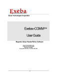
B.A.S.I.S.® Offline Setup Guide • • • • • • Copyright © 2004 Stanley Security Solutions, Inc. and Stanley Logistics, Inc. All rights reserved. Printed in the United States of America. Information in this document is subject to change without notice and does not represent a commitment on the part of Stanley Security Solutions, Inc. The software described in this document are furnished under a license agreement or nondisclosure agreement. This publication is intended to be an accurate description and set of instructions pertaining to its subject matter. However, as with any publication of this complexity, errors or omissions are possible. Please call your Stanley Security Solutions, Inc distributor or Best Access Systems at (317) 849-2250 if you see any errors or have any questions. No part of this manual and/or databases may be reproduced or transmitted in any form or by any means, electronic or mechanical, including photocopying, recording, or information storage and retrieval systems, for any purpose, without the express written permission of Stanley Security Solutions, Inc. This document is distributed as is, without warranty of any kind, either express or implied, respecting the contents of this book, including but not limited to implied warranties for the publication’s quality, performance, merchantability, or fitness for any particular purpose. Neither Stanley Security Solutions, Inc, nor its dealers or distributors shall be liable to the user or any other person or entity with respect to any liability, loss, or damage caused or alleged to be caused directly or indirectly by this publication. The Best Access Systems logo and B.A.S.I.S. are registered trademarks of Stanley Security Solutions, Inc. Microsoft, Windows, CE, and ActiveSync are registered trademarks of Microsoft Corporation. T80946/Rev B ER-7991-40 April 2004 Contents 1 Introduction Related documents 1–1 Getting technical support 1–2 How to use this guide 1–2 2 Architectural overview B.A.S.I.S. online and offline diagram 2–3 How B.A.S.I.S. G ‘Guest’ locks work 2–4 Components and connections 2–6 Feature comparison of B.A.S.I.S. G and B.A.S.I.S. V 2–7 Setup overview 2–10 3 First-time B.A.S.I.S.® Offline System Configuration Installing the system 3–2 Defining the system 3–7 i 4 Setting up and Maintaining B.A.S.I.S.® Offline Locks Introducing B.A.S.I.S. Transport 4–1 Programming locks 4–2 Retrieving history records 4–11 Using diagnostics features 4–14 5 Managing B.A.S.I.S.® G Cardholders Editing cardholders 5–2 Searching for cardholders 5–10 Encoding existing cardholders 5–12 A Glossary of Terms Terms A–2 ii C h a p t e r 1 Introduction Thank you for choosing B.A.S.I.S.® G and V, the world’s leading combination online and offline access control system. Use this guide to make sure that you set up your system in the most efficient way and to get the most out of it. The initial setup of the B.A.S.I.S. G & V system is not trivial, but if done thoroughly it will pay many dividends. Related documents The following documents are available to help you install, maintain, or operate other related systems. See your BEST Representative for more information. ■ ■ ■ ■ ■ B.A.S.I.S. V Service Manual B.A.S.I.S. G Service Manual Alarm Monitoring User Guide BadgeDesigner™ User Guide FormsDesigner™ User Guide 1–1 Chapter 1: Introduction ■ Notes ■ ■ ■ ■ ■ ■ ■ ■ ■ ■ ■ ■ ■ ■ ■ ■ ■ ID CredentialCenter User Guide Basic Import Utility User Guide Installation & Setup User Guide MapDesigner™ User Guide System Administration User Guide Universal Interface Server User Guide Replicator User Guide View/Edit Only Workstation User Guide Alternative Wiring Configurations Guide Legato® Co-StandbyServer™ User Guide Hardware Installation Guide Visitor Management User Guide Area Access Manager User Guide Digital Video User Guide Video Archive Server User Guide Replication Administration User Guide Digital Video Hardware User Guide B.A.S.I.S. Interface User Guide Getting technical support Best Access Systems Representatives provide telephone technical support for all B.A.S.I.S. V products. You may locate the representative nearest you by calling 317-849-2250 Monday through Friday, between 7:00 am and 4:00 pm, eastern standard time, or visit us on the web at www.bestaccess.com. How to use this guide This manual is intended for use as a training guide and a reference in the setup of a B.A.S.I.S. offline system. Chapter 2, Architectural Overview – This chapter provides an overview of the B.A.S.I.S. online and offline worlds. If you are already familiar with B.A.S.I.S. online and offline systems, you can safely skip this chapter. Chapter 3, First-time system configuration – This chapter provides complete step-by-step instructions in the proper setup of a new offline system. Chapter 4, Setting up and maintaining offline locks – This chapter provides complete step-by-step instructions on the proper setup of offline locks. Chapter 5, Managing B.A.S.I.S. G Cardholders – This chapter provides complete step-by-step instructions on adding, modifying, deleting and searching cardholders. 1–2 Chapter 1: Introduction Appendix A, Glossary – This appendix provides a list of terms that are specifically used in the B.A.S.I.S. software. Terms that appear in the glossary are set in italics when they are first used. 1–3 Notes Chapter 1: Introduction 1–4 C h a p t e r 2 Architectural overview This chapter describes the ‘big picture’ of the online B.A.S.I.S.® access control system world and how the offline B.A.S.I.S. G and V product fits into that world. The B.A.S.I.S. product line is composed of two general architectural models used to address the security needs of most customer requirements and applications. These two models can be generally categorized as online and offline. In an online application most access control decisions are performed by a component called an Intelligent System Controller (ISC) or Access Panel. The ISC is a circuit board with on-board memory, and this on-board memory must be configured by users who understand access control functions and features. 2–1 Chapter 2: Architectural overview Notes This configuration is accomplished through an operator entering data on or through a computer called a server. In the world of B.A.S.I.S. this server is a computer where the access control system database resides. An operator can enter configurations in the server database through a B.A.S.I.S. application that resides on the server or through one of many possible B.A.S.I.S. workstations that exist on the access control network. 2–2 Chapter 2: Architectural overview B.A.S.I.S. online and offline diagram Notes The B.A.S.I.S. system is capable of being configured as both an online and an offline access control system. This means that with B.A.S.I.S. you can manage readers, locks, controllers, in fact, any access control hardware, whether or not they are wired directly to a panel or not. This diagram describes a typical combined online and offline B.A.S.I.S. system. Figure 2.1 B.A.S.I.S. online and offline diagram overview Encoder PDA B.A.S.I.S. G/V Workstation Workstation Server LAN/WAN ISC RIM RIM RQE B.A.S.I.S. Offline Lock IDH Max Lock Alarm Output Board CR LK Siren Strobe DC Alarm Input Board Motion detectors Glass brk sensors Tamper sensor Analog Camera Analog Camera B.A.S.I.S. CR DC IDH Max ISC LAN LK PDA RIM RQE WAN Best Access Systems Integrated Solutions Card Reader Door Contact Integrated Door Hardware Lock Intelligent System Controller Local Area Network Lock Personal Digital Assistant Reader Interface Module Request-to-exit switch Wide Area Network Video Server IP Camera IP Camera 2–3 Chapter 2: Architectural overview Notes How B.A.S.I.S. G ‘Guest’ locks work B.A.S.I.S. G offline locks are designed primarily for the college and university dormitory. But they can be effectively used in any application where a room has continuous occupancy change over a period of time, or where the lock location is remote or isolated enough that going out to reprogram the lock becomes undesirable. Guest functionality then is the lock feature that enables you to add and delete users to and from the lock without having to go out and visit the lock to reprogram it. Operation B.A.S.I.S. G allows that a range of badge numbers be pre-programmed into the lock unit securing a dormitory room. These badge numbers are available for issue and reuse as students are assigned to their dormitory accommodations. The badge number is automatically issued to a student when the lock for the room is chosen in the cardholder setup screen. The card number from the assigned range can then be encoded and presented to the student for use in his or her assigned room. New students may be assigned access to a particular room by using badge IDs from the same range without ever needing to re-program the lock. By taking advantage of the issue code look ahead feature, a badge ID issued with an incrementally higher issue code will deactivate any other like badge ID for the lock. The following diagram describes the design and process that B.A.S.I.S. G locks use to achieve the guest functionality. 2–4 Chapter 2: Architectural overview Figure 2.2 1001 issue code: 01 1001 issue code: 00 Lost card Notes Guest functionality diagrammed Issue codes 00 01 02 03 Newly encoded card Issue codes offset of 1 range of 3 valid issue codes 01 02 03 04 lost card does not work new offset new range Auto update B.A.S.I.S. G Lock Same B.A.S.I.S. G Lock after use of the 1001 issue code 01 card The diagram uses the following issue code look ahead values: Look ahead function Value Offset 1 Range 3 Number of issue code digits 2 Also instructive is to see what happens when the issue code has reached its limit. Let’s look at another diagram to see what happens in this case. The issue code look ahead values remain the same. 2–5 Chapter 2: Architectural overview Notes Figure 2.3 1001 issue code: 00 1001 issue code: 99 Lost card Guest functionality in rollover diagrammed Issue codes 00 01 02 Newly encoded card offset of 1 range of 3 valid issue codes Issue codes 00 01 02 03 new offset new range lost card does not work Auto update B.A.S.I.S. G Lock Same B.A.S.I.S. G Lock after use of the 1001 issue code 00 card Components and connections The following diagram describes the system ‘family’ – all the types of hardware and software that it takes to create an offline B.A.S.I.S. system. Components include: ■ ■ ■ ■ ■ ■ 2–6 B.A.S.I.S. software, version 5.8, build 41b or higher Dedicated computer, see your BEST representative for complete details B.A.S.I.S. G or V lock, includes cylindrical, mortise or exit hardware trim models Personal digital assistant (PDA). See www.bestaccess.com for supported models. Encoder ■ magnetic stripe ■ smart card (contact the factory for proper application) Cables ■ computer to PDA ■ PDA to lock (requires PDA proprietary cable and BEST part number BASD-CAB). Chapter 2: Architectural overview Feature comparison of B.A.S.I.S. G and B.A.S.I.S. V Notes The differences between B.A.S.I.S. G and B.A.S.I.S. V can be confusing since they share many of the same features. The following table compares the two systems side by side. B.A.S.I.S. Feature Description G V Guest (dormitory feature Provides the ability to issue pre-created badge ID's to students. This supports the assignment of one reader directly to the badge. Other readers may be assigned to the badge through normal access level assignment. ■ ■ Look ahead Issue code look ahead feature through offset and range fields. ■ ■ Encoding Provides the ability to encode both magstripe and smart cards from the cardholder/badge tab. Smart cards are encoded using magstripe or Wiegand simulated formats. ■ ■ Passage mode Allows the cardholder to place the reader into an unlocked mode. This status is cleared only by another passage mode attempt or reader mode change occurrence. ■ ■ Deadbolt override Allows the cardholder to retract the deadbolt. ■ ■ Key override event An event logged into history whenever the key override feature is used in a mortise lock. Not supported in Cylindrical. ■ ■ Use activation date Determines if the lockset will use the activation date field stored in the cardholder record when validating. This option has no impact on Dormitory functionality. ■ Use deactivation date Determines if the lockset will use the deactivation date field stored in the cardholder record when validating. This option has no impact on Dormitory functionality. ■ Two card control Requires that two valid users must present their cards in order to unlock the door. ■ Enforce use limit Allows for the temporary use of cards. After a certain number of uses the card is disabled. The number of uses is configured through the badge tab. ■ 2–7 Chapter 2: Architectural overview Notes Feature Description B.A.S.I.S. G V Denied attempts Includes attempts count and time out duration. Sometimes referred to as ‘Three strikes your out.’ Logging (grant, denies, status) Provides the ability to filter the displaying/ logging of history events. This feature is implemented at the Management System level. ■ ■ always logged configurable Daylight saving time Support for all OS world time zones. ■ ■ 128K RAM 5000 Users/History ■ ■ Card formats (8) Support for up to eight card data formats per reader. Facility codes are assigned through card formats. ■ ■ Magnetic 5 bit ABA data only track 3 tracks 1&2 Wiegand Any valid Wiegand format Online mode Automatic (time zone control of reader mode), Facility Code, Card Only, Unlocked, Locked, Card and Pin, and Card or Pin. ■ ■ Reader modes (automatic unlock/ relock) This feature provides the ability to change operational modes at specified periods through time zone control. The current modes would be Facility Code, Card Only, Unlocked, Locked, Card and Pin, Card or Pin, and First Card Unlock. 2 32 Unlock duration The amount of time that the lockset will remain unlocked for a valid access grant. ■ ■ Extended unlock This feature provides the ability to extend the unlock duration for certain cardholders. ■ ■ Chassis type Cylindrical & Mortise with support for a user defined type ‘Custom’. ■ ■ Holidays Special days of the year can be categorized as one of eight types. 8 32 Time zones Time Zones are necessary for the use of Access Levels. A time zone can be comprised of up to six intervals. 4 32 Access levels Access Level assignment to readers. ■ ■ Battery warn/ alarm Reported through the activation of LED’s and the lock internal sounder. ■ ■ Panel password Communication password is configured at the Access Panel level. ■ ■ Diagnostics (PDA) The PDA will support the capability of performing diagnostics on the lockset. ■ ■ 2–8 ■ ■ Chapter 2: Architectural overview Feature Description Notes B.A.S.I.S. G V Cycle count/ reset The lockset will maintain a current count of access grants. The count can be reset by the user. ■ ■ DIagnostics code This code provides some feedback of the lockset's status. ■ ■ Backup battery level Displays the current level of the backup battery. ■ ■ Displays the current level of the main electronics battery. ■ ■ This feature allows for the unlocking of the door for the unlock duration. ■ ■ This feature allows for the setting of the current operating mode directly to the reader through the PDA. This action would override the online mode set at the management system level. All online reader modes are supported. ■ ■ Dual Validation ■ ■ Magstripe track 3 tracks 1&2 Smart Card ■ ■ Electronics level Unlock once Reader mode Reader support Batch update HID Proximity ■ Motorola Proximity ■ This feature allows for the bulk updating of Activation/Deactivation Dates. ■ ■ 2–9 Chapter 2: Architectural overview Notes Setup overview In the next chapter you will find complete step-by-step instructions on the first-time configuration of a B.A.S.I.S.® offline system. But listed here are the major steps of that process and cross-references where you can find each corresponding task. Task 1 Install the system components. This task begins on page 3-2. ■ B.A.S.I.S. Software, see page 3-2. ■ Encoder, see page 3-3. ■ PDA, see page 3-5. ■ B.A.S.I.S. Transport, see page 3-6. Task 2 Define the system. This task begins on page 3-7. ■ Card formats, see page 3-7. ■ Badge types, see page 3-9. ■ ‘Virtual’ offline access panels, see page 3-13. ■ Guest readers, see page 3-15. Task 3 2 – 10 For B.A.S.I.S. V configuration only, set up time zones, holidays, access levels, and cardholders. C h a p t e r 3 First-time B.A.S.I.S.® Offline System Configuration You are now ready to start setting up your B.A.S.I.S.® offline system. The following tasks do not include the installation of the locks themselves. The installation of the B.A.S.I.S. G or B.A.S.I.S. V locks are fully described in the following installation instruction documents. Contact your BEST Representative for a copy of these documents: Title Doc number Installation Instructions for Electronic Stand-alone Cylindrical Locks T61835 Installation Instructions for Electronic Stand-alone Mortise Locks T61836 Installation Instructions for Electronic Stand-alone Exit Hardware Trim T61828 3–1 Chapter 3: First-time B.A.S.I.S.® Offline System Configuration Notes Make sure that the B.A.S.I.S. G or V locks are at least on site and ready to be programmed. Locks may be programmed before installation. Installing the system Make sure that you have the following components before you start installing the B.A.S.I.S. Offline system: ■ ■ ■ ■ ■ B.A.S.I.S. software, version 5.8, build 41b or higher Dedicated computer, see your BEST representative for complete details. Personal digital assistant (PDA). See www.bestaccess.com for supported models. Encoder, ■ magnetic stripe ■ smart card (contact the factory for proper application) Cables ■ computer to PDA ■ PDA to lock (requires PDA proprietary cable and BEST part number BASD-CAB). Installing the B.A.S.I.S. software Before installing the B.A.S.I.S. software, also make sure that you have completed the following checklist. Determine whether your database will use Microsoft SQL Server, Oracle, or MSDE. Make sure you have an Information Technology person who can configure the computer’s TCP/IP protocol. Make sure you have an Information Technology person who can set up a server with the appropriate server software. Get the hardware key or ‘dongle.’ For complete B.A.S.I.S. online software installation and configuration, see the B.A.S.I.S. Installation and Setup User Guide. Contact your BEST Representative for a copy. 3–2 Chapter 3: First-time B.A.S.I.S.® Offline System Configuration Installing the encoder Notes Two types of encoders are available for the B.A.S.I.S. Offline system: ■ Magnetic stripe encoder Unitech model MSR206 part number MSR206-33 ■ Smart card encoder GemPlus model GEMPC410 part number GCR410-P BEST part number 1825235 For proper setup of the smart card encoder, contact your BEST Representative. The card encoder or some type of encoding device (that is, an encoder or a printer with a built-in encoder) is required for B.A.S.I.S. G locks. So the following instructions are required for B.A.S.I.S. G functionality, but optional for B.A.S.I.S. V. For a comparison of B.A.S.I.S. G and V, See “Feature comparison of B.A.S.I.S. G and B.A.S.I.S. V” on page 2-7. These instructions assume a stand-alone encoder. To set up the encoder 1 Click Start > Programs > B.A.S.I.S. ET > System Administration. 2 At the login window type your user name and password and then click OK. If you do not know your user name or password, see your System Administrator. 3 Click Administration > Workstations. 4 From the Workstation tab, confirm that the name of your computer is in the list. If your computer is not in the list, add your workstation by using the browse button and select your workstation. 5 Click Add. 6 Type the name of your computer or click the browse button and browse the network for your computer. 7 Click OK. 8 Click the Encoder tab. 9 Confirm that the encoder is physically connected to a COM port on the computer, preferably COM1, and is powered on. 3–3 Chapter 3: First-time B.A.S.I.S.® Offline System Configuration Notes 10 Click Add. Figure 3.1 Configuring the encoder Click to test whether the encoder is online 11 Under Encoder Settings, in the name field, type a name for the encoder. 12 In the Encoder Type field, select: Magstripe Swipe Reader/Writer (Model 712 or 722) 13 Click Test. Note The encoder can be tested at any time by returning to the Encoder tab. You do not need to put the encoder in modify mode to test the encoder. 14 Click OK. 15 Close System Administration. 3–4 Chapter 3: First-time B.A.S.I.S.® Offline System Configuration Installing the PDA Notes The Personal Digital Assistant (PDA) is your link from the B.A.S.I.S. workstation to the B.A.S.I.S. G and V lock. With the help of your computer network administrator, if necessary, perform the following steps to set up the connection between the PDA and the B.A.S.I.S. workstation. To install Microsoft ActiveSync 1 Connect the PDA to the B.A.S.I.S. workstation. 2 Install Microsoft ActiveSync. 3 When prompted, set up a partnership with this computer and remove all check marks associated with programs. 4 Restart the computer after ActiveSync completely installs. 5 Test the encoder and confirm ActiveSync connectivity before proceeding. To test the encoder, see page 3-4. Note When ActiveSync is running, the ActiveSync icon, shown in the taskbar on the PC’s desktop, is green. When ActiveSync is not running, the icon is gray. 3–5 Chapter 3: First-time B.A.S.I.S.® Offline System Configuration Installing B.A.S.I.S. Transport Notes Confirm that the following requirements are met for running B.A.S.I.S. Transport. For detailed instructions see the B.A.S.I.S. Installation & Configuration User Guide. B.A.S.I.S. System Administration is installed. B.A.S.I.S. Communication Server is installed. Microsoft ActiveSync is installed. A connection is established between the PDA and the PC using ActiveSync. Note Before you can install B.A.S.I.S. Transport, you must establish a connection between the PDA and the B.A.S.I.S. PC. To install B.A.S.I.S. Transport You install B.A.S.I.S. Transport from the B.A.S.I.S. CD #1 onto the PDA from the host with a connection established through ActiveSync. 1 Open an Explorer window for B.A.S.I.S. CD #1. Stop the auto-run of the B.A.S.I.S. installation wizard if it starts. 2 Navigate to the B.A.S.I.S. Transport folder. 3 Double-click the Transport executable (program) file. The B.A.S.I.S. Transport Setup wizard appears. 4 Follow the on-screen instructions. 3–6 Chapter 3: First-time B.A.S.I.S.® Offline System Configuration Defining the system Notes Overview To define a B.A.S.I.S.® G or B.A.S.I.S. V system, you need to configure: Card formats Badge types ‘Virtual’ offline access panels Guest readers Although B.A.S.I.S. locks are offline (stand-alone) and are not managed by access control panels, you must define Access Panel settings for the locks. In effect, you define ‘virtual’ access control panels for the locks. More than one lock – called a reader in B.A.S.I.S. – can share the same panel configuration. However, these locks (readers) must all: ■ be managed by the same B.A.S.I.S. PC ■ share the same password ■ be located in the same time zone ■ use the same daylight saving time setting. Defining card formats Defining a card format is the starting point to configuring a B.A.S.I.S. G system. But if B.A.S.I.S. G functionality is not needed, a standard card format can be used or configured for a reader assignment through access levels. Badges using standard formats on compatible tracks can only be assigned readers through access levels. To define a card format 1 From System Administration, click Administration > Card Formats. The Card format form displays 2 Click Add. The Choose Card format type window displays 3–7 Chapter 3: First-time B.A.S.I.S.® Offline System Configuration Notes Choose the appropriate card format 3 Choose the appropriate card format and click OK. The modify card format window displays Figure 3.2 Defining card formats When the guest format check box is selected, the data is offset from the start of the card by the fact that the activation and deactivation dates are encoded onto the card. Set the access control track to 3. Make sure to adjust the total characters on the track to the correct access control data length. A two-digit issue code is preferred for B.A.S.I.S. G. Define the name, facility code, total characters, and the guest format. 3–8 Chapter 3: First-time B.A.S.I.S.® Offline System Configuration 4 Type the name of the card format. A typical name for the guest format is ‘Guest format.’ 5 Complete all appropriate fields including facility code, access control track, total characters on track, and the guest format check box. Defining badge types To use B.A.S.I.S. G functionality, you must define a guest badge type. This badge type allows you to define and allocate a range of badge ID numbers that will be programmed into the lock. Badge type is an ID Credential Center function used in the configuration of Guest products and determines the block or pool of badge numbers to be allocated to a group of locks. Also, badge type determines the card format to be encoded on the badge. In this instance think of the badge type as a way of allocating a block of badge numbers to a facility, building, or other group of related guest locks. Application note A badge type could be used to allocate a pool of badge numbers for a dormitory from which smaller blocks of numbers could be obtained for the individual dormitory units. 3–9 Notes Chapter 3: First-time B.A.S.I.S.® Offline System Configuration Notes To define a guest badge type 1 From System Administration, click Administration > Badge Types. The Badge Types form displays 2 Click Add. The modify badge type window displays Figure 3.3 type Selecting the Guest class for B.A.S.I.S. G badge Choosing the Guest classification enables the features of the Badge ID Allocation tab. 3 Select the Guest class from the drop down box. 4 Complete all other necessary information on the tab. 5 Click the Printing/Encoding tab The Printing/Encoding tab badge type displays 3 – 10 Chapter 3: First-time B.A.S.I.S.® Offline System Configuration Notes Figure 3.4 Making sure that the Guest Card format is selected for printing and encoding Make sure that the Guest format is selected for encoding Guest Badge Types. 6 Select the appropriate card format to be encoded for the badge type. 7 Make sure that a check mark appears next to the selected card format. 8 Click the Badge ID Allocation tab. The Badge ID Allocation window displays 3 – 11 Chapter 3: First-time B.A.S.I.S.® Offline System Configuration Notes Figure 3.5 Entering the range of Badge IDs Enter the appropriate range of badge IDs for your application. 9 Enter the First ID number in the badge range that you want to create. Application note Make sure to allocate a range of badge numbers that will facilitate the future growth of a group of locks. The size of the range will determine the length of the reader list in the ‘Allow Access To’ drop-down selection on the Badge tab under Cardholders. 10 Enter the number of Badge IDs that you want to create. 11 Click Add. 12 Click OK. 3 – 12 Chapter 3: First-time B.A.S.I.S.® Offline System Configuration Defining ‘virtual’ offline access panels Notes Although B.A.S.I.S. Locks are offline (stand-alone) locks and are not managed by access control panels, you must define Access Panel settings for the locks. In effect, you define ‘virtual’ access control panels for the locks. Using the virtual access panel concept allows the programming of guest locks to follow the same conventions as B.A.S.I.S. online products. Up to 64 locks (called a ‘reader’ in B.A.S.I.S.) can share the same panel configuration. However, these locks ‘readers’ must all: ■ be managed by the same B.A.S.I.S. PC ■ share the same password ■ be located in the same time zone ■ use the same daylight saving time setting. Note The default password is ‘BEST.’ Care should be given to faithfully document any changes to this password since the password cannot be viewed from anywhere in the B.A.S.I.S. application software. To define a ‘virtual’ offline access panel 1 From System Administration, click Access Control > Access Panels. 2 Click the Offline Lock tab. 3 Click Add. The Offline Lock Access Panel window displays 3 – 13 Chapter 3: First-time B.A.S.I.S.® Offline System Configuration Notes Figure 3.6 Naming the offline lock access panel Name the offline lock access panel appropriately for all of the possible 64 locks that it controls. The workstation name refers to the technical name of the computer to which the PDA is attached. 4 In the Name field, type the name of the ‘virtual’ access control panel. 5 Click OK. 6 Repeat steps 3 and 4 as necessary. 3 – 14 Chapter 3: First-time B.A.S.I.S.® Offline System Configuration Defining the Guest reader/lock Notes In the B.A.S.I.S. software locks are referred to as readers to conform and maintain consistency with B.A.S.I.S. online terminology conventions. You can define up to 64 readers or locks for each ‘virtual’ offline access control panel. And each reader or lock will accept up to eight different card formats. It would be highly unusual to use this many formats in one lock. In this section you will define a guest reader or lock. To define a Guest reader/lock 1 From System Administration, click Access Control > Readers. 2 Click the Reader tab – if not already on the reader tab. 3 Click Add. The Add Reader window displays Figure 3.7 Defining offline guest readers Selecting the Guest reader type enables the assignment of a subset of badge numbers from the larger range of numbers configured for a Badge Type. The automatic setting for ‘online reader mode’ allows the lock to use time zone control and token control when programmed for both. 4 In the Name field, type the name of the reader. 5 In the Panel field, select the ‘virtual’ offline access control panel that controls the reader. 6 In the Type field, select Guest. 7 Select the appropriate reader mode. 3 – 15 Chapter 3: First-time B.A.S.I.S.® Offline System Configuration Notes 8 Under the Card Format section, select the Guest Card Format. Application note Selecting the ‘Offline Guest’ reader type refers to a B.A.S.I.S. V configuration. A selection of the Offline reader type is not recommended. 9 Make any other selections as necessary. 10 Click OK. The Reader is listed in the Reader listing at the top of the window. 11 Repeat steps 3 – 10 for each additional lock/reader. Now that you have defined the reader operation of the lock/ readers, you now need to configure the software so that the correct chassis type is assigned to the lock/reader and other offline features are configured appropriately. Before you can complete this section you must know: ■ Chassis type of the lock/reader. The chassis type will most likely be either mortise or cylindrical. ■ The maximum number of cardholders that will need to access the lock/reader. This includes both guest cardholders and those cardholders that access the reader by access levels. ■ The number of guest badges that will be assigned from the pool of badge IDs. 3 – 16 Chapter 3: First-time B.A.S.I.S.® Offline System Configuration To define other guest reader features Notes 1 From System Administration, click Access Control > Readers. 2 Click the Offline tab. 3 Select the Reader that you want to define. Make sure that the check mark is next to the reader to be modified. 4 Click Modify. The Modify Offline Reader window displays Figure 3.8 Defining the offline reader Make sure that the correct reader is selected when selecting offline features The common door feature allows duplication of a badge range between locks. The number of events is automatically calculated based on the amount of lock memory and the number of cardholders allocated. 5 In the Chassis Type field, select the chassis type that the lock/reader has. Application note The custom chassis type enables the modification of the chassis volume. The chassis volume is a value used by engineers that relates to the number of turns of the motor that is required to unlock the lock. Only use the custom chassis type at the direction of a technical support engineer or specific instructions enclosed with the lock. 6 In the Cardholders field, select the total number of cardholders that will need to access the lock/reader. 7 In the Look Ahead section, select the look ahead offset and range. Normally for B.A.S.I.S. G locks, the offset is set to 1 and the range to 3. For more information on guest functionality, see page 2-4. 3 – 17 Chapter 3: First-time B.A.S.I.S.® Offline System Configuration Notes 8 In the Guest Parameters section, select whether the lock/ reader will be a Common door. 9 In the Badge Type field, select a guest badge type from the list that was created. See page 3-9. 10 In the Number of badges field, enter the number of guest badges to be allocated to this lock/reader from the total pool of badge IDs. 11 For a common door only: In the Badge Start Number field, enter the starting badge number for the subset of numbers to be used in this lock/reader. The badge end number is automatically calculated from the numbers entered. 12 Click OK. 13 Repeat steps 3 – 12 for each lock/reader to be defined. B.A.S.I.S. G Lock/reader programming is now complete If you have finished the tasks up to this point, you have completed all steps necessary for the programming of B.A.S.I.S. G functionality. However, for B.A.S.I.S. V functionality, that is, the use of time zones, access levels, holidays, etc, that you may want to use for B.A.S.I.S. G lock/readers, see the B.A.S.I.S. System Administration User Guide. For a complete list of features comparing B.A.S.I.S. V and B.A.S.I.S. G, see “Feature comparison of B.A.S.I.S. G and B.A.S.I.S. V” on page 2-7. Note 3 – 18 If you assign cardholders using access levels to B.A.S.I.S. G lock/readers, you will need to use the PDA to update the locks. C h a p t e r 4 Setting up and Maintaining B.A.S.I.S.® Offline Locks This section describes how to use your B.A.S.I.S.® Transport software. The following topics are covered. Introducing B.A.S.I.S. Transport The B.A.S.I.S. Transport software application lets you: ■ program B.A.S.I.S. G and B.A.S.I.S. V Locks by transferring reader configurations from B.A.S.I.S. System Administration to the locks ■ transfer history records from B.A.S.I.S. Locks to System Administration ■ view diagnostics information for B.A.S.I.S. Locks. In addition, you can use Transport to unlock a B.A.S.I.S. Lock without using a card or PIN. You also can change the lock’s mode of operation. . 4–1 Chapter 4: Setting up and Maintaining B.A.S.I.S.® Offline Locks Notes Programming locks To program a B.A.S.I.S. G or B.A.S.I.S. V Lock, you need to: Define an access control panel and reader configuration for the lock using B.A.S.I.S. System Administration. For more information, see page 3-7 of this guide as well as the B.A.S.I.S. System Administration User Guide. Transfer the reader configuration from the PC to the PDA. See the next section. Transfer the reader configuration from the PDA to the lock. See page 4-10. Transferring reader configurations from the B.A.S.I.S. PC to the PDA After you have used System Administration to create the reader configurations for the locks you want to program, you can transfer the reader configurations from the B.A.S.I.S. PC to the PDA. Perform these steps: To transfer reader configurations from the B.A.S.I.S. PC to the PDA 1 Establish an ActiveSync connection between the PDA and PC. Note When ActiveSync is running, the ActiveSync icon, shown in the taskbar on the PC’s desktop, is green. 2 On the PDA, make sure B.A.S.I.S. Transport is not running. To exit Transport, see page 4-10. 3 On the PC, launch B.A.S.I.S. System Administration and B.A.S.I.S. Communication Server. 4 From the System Administration main menu, click View, then System Tree. See Figure 4.1 4–2 Chapter 4: Setting up and Maintaining B.A.S.I.S.® Offline Locks Figure 4.1 Notes System Administration System Tree You can expand the entries in the System Tree to see the hierarchy of access control devices in your system. To expand an entry, click the plus sign (+) to the left of the entry. To collapse an entry, click the minus sign (–) to the left of the entry. 5 Expand the Hardware entry to view the access control panels defined for your system. Expand the access control panels to view the readers defined for your system. See Figure 4.2. Figure 4.2 Note Expanding the System Tree to view readers If a reader configuration has been created or updated at System Administration, but has not yet been sent to the PDA, a red “X” appears on the reader’s icon, as well as on the icon for the reader’s access panel. 6 Highlight the reader that you want to transfer to the PDA. 4–3 Chapter 4: Setting up and Maintaining B.A.S.I.S.® Offline Locks Notes To highlight multiple readers, hold down the Ctrl key and click each reader. 7 Right-click on the selection in the System Tree. The menu shown in Figure 4.3 appears. Figure 4.3 Right mouse button menu for readers in the System Tree Use the right mouse button on any reader to display this menu. 8 Click Download. The PC begins transferring the highlighted reader configurations to the PDA. 9 If that reader or panel already exists on the PDA, the PDA will display a dialog requesting to overwrite the old version of the reader. Tap OK. 10 On the PDA, watch the messages indicating the progress of the transfer. 11 When the transfer is complete, a message appears stating, “Complete download successful.” On the PDA, tap OK. 12 To disconnect the PDA from the PC, disconnect the PDA from the ActiveSync connection. 4–4 Chapter 4: Setting up and Maintaining B.A.S.I.S.® Offline Locks Transferring a configuration from the PDA to a lock The sections below provide instructions for sending a panel/ reader configuration to a B.A.S.I.S. G or B.A.S.I.S. V Lock. To connect the PDA to a lock See Figure 4.4 and perform these steps: Figure 4.4 Connecting the PDA to a lock PDA Serial cable Communication port Programming cable 1 Connect the serial cable to the PDA. 2 Connect the serial cable to the programming cable. 3 Connect the programming cable to the lock’s communication port. The connector snaps into place. 4–5 Notes Chapter 4: Setting up and Maintaining B.A.S.I.S.® Offline Locks Notes To start B.A.S.I.S. Transport On the PDA, tap Start, then Programs, then BAS, then Transport. The Main window appears, as shown in Figure 4.5 Figure 4.5 B.A.S.I.S. Transport Main window To transfer a panel/reader configuration to a lock 1 Connect the PDA to the lock. See page 4-5. 2 Start B.A.S.I.S. Transport. See page 4-6. 3 From the B.A.S.I.S. Transport Main window on the PDA, tap View, then Transport. The Transport window shows the Panel/Reader Tree. You can expand the entries in the Panel/Reader Tree to see the hierarchy of access control panel/reader configurations on the PDA. See Figure 4.6 4–6 Chapter 4: Setting up and Maintaining B.A.S.I.S.® Offline Locks Figure 4.6 Notes Panel/Reader Tree Click the minus sign to collapse. Click the plus sign to expand. To expand a panel, tap the plus sign (+) to the left of the panel. To collapse a panel, tap the minus sign (–) to the left of the panel. 4 Highlight the reader configuration that you want to transfer to the lock. 5 Tap Transport, then Configure Lockset. The Login window appears, as shown in Figure 4.7. Figure 4.7 Login window 6 If you are programming the lock for the first time: a Leave the Enter Password field blank. Note B.A.S.I.S. Locks do not have a factory-programmed default password. b Ignore the Preserve user pins checkbox. c Tap OK. 4–7 Chapter 4: Setting up and Maintaining B.A.S.I.S.® Offline Locks Notes A message appears stating, “Attempting login . . . Please swipe a card . . . .” d Use the temporary operator card to activate the lock. A message appears asking, “Reader ID’s don’t match. Continue anyway?” 7 Tap Yes. The PDA begins transferring the selected reader configuration to the lock. On the PDA, watch the messages indicating the progress of the transfer. When the transfer is complete, a message appears stating, “Configuration data transfer successful.” 8 Tap OK. A message appears asking, “Delete this reader?” 9 We recommend that you tap Yes to delete the reader configuration. The reader configuration no longer appears in the Panel/Reader Tree. Note If you want to use this reader configuration for another lock, tap No. 10 To return to the Main window, tap View, then Main. 11 To disconnect the PDA from the lock, press the button on the programming cable connector and unplug the programming cable from the lock’s communication port. See Figure 4.8 4–8 Chapter 4: Setting up and Maintaining B.A.S.I.S.® Offline Locks Notes Figure 4.8 Disconnecting the programming cable from the lock Button on the programming cable connector If you are updating the configuration for the lock: 1 Enter the lock’s password in the Enter Password field. For instructions to use the PDA’s virtual keyboard, see the documentation provided with the PDA. Note The password for a lock is the password programmed for the reader in the virtual access control panel. You must enter the password exactly as it was entered in the Password field on the Offline Lock form in the Access Panels folder. Capitalization must be the same. The default password is ‘BEST.’ If the lock has a dual validation reader (with keypad): ■ To keep the user PINs already programmed, place a check in the Preserve user pins checkbox. ■ Or, to reprogram the lock with the PINs stored in B.A.S.I.S., remove the check from the Preserve user pins checkbox. Caution If users have reprogrammed their PINs at the lock and you do not preserve the user PINs, users will no longer be able to access the lock. 4–9 Chapter 4: Setting up and Maintaining B.A.S.I.S.® Offline Locks Notes To manually change the PIN in a B.A.S.I.S. dual validation lock If you must use your card and PIN to unlock the door during some or all time periods, change your PIN periodically for added security. You can change your PIN only during a time period when both your card and PIN are required to unlock the door. For more information about changing a lock’s mode, see page 4-17. Caution Do not write your PIN on your card or in a place where someone might see it. 1 Use your card at the lock. 2 From the lock keypad, immediately enter: * + your current PIN + # The red light remains on, indicating that you can change your PIN. 3 Immediately enter: your new PIN + # 4 Immediately re-enter: your new PIN + # The green light flashes to indicate that you successfully changed your PIN. Note Example of changing your PIN If you make a mistake re-entering your new PIN, three short tones sound and the red light turns off. Start over with step 1 and use your old PIN for step 2. 1 Use your card. 2 Enter *1234# 3 Enter *4321# 4 Re-enter * 4 3 2 1 # To exit B.A.S.I.S. Transport From the B.A.S.I.S. Transport Main window on the PDA, tap View, then Exit. 4 – 10 Chapter 4: Setting up and Maintaining B.A.S.I.S.® Offline Locks Retrieving history records Notes History retrieval overview To retrieve and view history records from a B.A.S.I.S. G or B.A.S.I.S. V Lock, you need to: ■ Transfer the history records from the lock to the PDA. See the next section. ■ Transfer the history records from the PDA to the B.A.S.I.S. PC. See page 4-13. ■ Use System Administration to generate reports using the transferred records. See page 4-13. You can retrieve history records from multiple locks and then transfer all of the records to the PC at the same time. Transferring history records from a lock to the PDA 1 Connect the PDA to the lock. See page 4-5. 2 Start B.A.S.I.S. Transport. See page 4-6. 3 From the B.A.S.I.S. Transport Main window on the PDA, tap View, then Transport. The Transport window shows the Panel/Reader Tree. Note When transferring history records from the lock, you do not need to highlight a reader in the tree. 4 Tap Transport, then Get History. The Login window appears, as shown in Figure 4.9. Figure 4.9 Login window 5 Enter the lock’s password in the Enter Password field. For instructions to use the PDA’s virtual keyboard, see the documentation provided with the PDA. 4 – 11 Chapter 4: Setting up and Maintaining B.A.S.I.S.® Offline Locks Notes Note The password for a lock is the password programmed for the reader configuration’s access control panel. You must enter the password exactly as it was entered in the Password field on the Offline Lock form in the Access Panels folder. Capitalization must be the same. 6 Tap OK. A message appears stating, “Attempting login . . . Please swipe a card . . . .” 7 Use the temporary operator card to activate the lock. The lock begins transferring its history records to the PDA. On the PDA, watch the messages indicating the progress of the transfer. When the transfer is complete, a message appears indicating the number of history records that were transferred. See Figure 4.10. Figure 4.10 History transfer completed message 8 Tap OK. 9 To return to the Main window, tap View, then Main. 10 To disconnect the PDA from the lock, press the button on the programming cable connector and unplug the programming cable from the lock’s communication port. See Figure 4.8 on page 4-9. You can view the history records only after they have been transferred from the PDA to the PC. You cannot view the history records on the PDA. 4 – 12 Chapter 4: Setting up and Maintaining B.A.S.I.S.® Offline Locks To Transfer history records from the PDA to the B.A.S.I.S. PC Notes 1 On the B.A.S.I.S. PC, launch B.A.S.I.S. System Administration and B.A.S.I.S. Communication Server. 2 Establish ActiveSync connection between the PDA and the PC. Note When ActiveSync is running, the ActiveSync icon, shown in the taskbar on the PC’s desktop, is green. When the connection has been established, the PDA automatically transfers all history records to the PC. On the PDA, watch the messages indicating that the PDA is uploading history records to the PC. When the history records have been uploaded, a message appears indicating the number of history records that were transferred. Note B.A.S.I.S. Transport does not need to be running during this process. Viewing history records After you have transferred lock history records from the PDA to the B.A.S.I.S. PC, you can use System Administration to generate reports using the records. For example, you can use the All Events Over Time report to view and/or print all of the history events transferred from the locks. For instructions, see the B.A.S.I.S. System Administration User Guide. 4 – 13 Chapter 4: Setting up and Maintaining B.A.S.I.S.® Offline Locks Notes Using diagnostics features Diagnostics overview Figure 4.11 B.A.S.I.S. Transport Domestics window You can use B.A.S.I.S. Transport to view diagnostics information for a lock. Figure 4.11 shows an example of the diagnostics information provided. The table below describes each of the fields in the Diagnostics window. This field Shows Firmware ID indicating the type of firmware in the lock. Technical ID support personnel may ask you to provide this information. Version Version number of the lock’s firmware. Technical support personnel may ask you to provide this information. 4 – 14 Chapter 4: Setting up and Maintaining B.A.S.I.S.® Offline Locks Notes This field Shows Diagnostics Code Hexadecimal number indicating firmware conditions, such as firmware resets, that have occurred at the lock since the diagnostics code was last cleared. The code 0x00 means no conditions have occurred. To view the meaning of the code, tap the more button (...). The Diagnostics Code window shows each active diagnostics code and its meaning. See Figure 4.12. Tap the close button (X) to close this window. Figure 4.12 window Diagnostics Code Technical support personnel may ask you to provide this information. To clear the diagnostics code, see page 4-20. Online Whether the lock is under time zone control (Automatic) or set to a specific mode, such as Locked or Mode Unlocked. For more information, see “Changing a lock’s online mode” on page 4–17. Use Count Number of times access was granted since the use count was last reset. To reset the use count, see page 4-19. Main Bat- Current power level of the lock’s battery pack. tery No shading in the status bar indicates an Alarm condition. The batteries are dead and must be replaced. If the shading falls within the Warning range, the power level is 30% or lower. You should replace the batteries soon. If the shading falls within the Good range, the power level is between 30% and 100%. Backup Current power level of the lock’s coin cell battery, used Battery to back up the lock’s memory if the main battery pack dies or is disconnected. If the backup battery is Bad, you should replace it. Refer to the B.A.S.I.S. G Service Manual (T63300) or the B.A.S.I.S. V Service Manual (T61805). 4 – 15 Chapter 4: Setting up and Maintaining B.A.S.I.S.® Offline Locks Notes To view diagnostics information 1 Connect the PDA to the lock. See page 4-5. 2 Start B.A.S.I.S. Transport. See page 4-6. 3 From the B.A.S.I.S. Transport Main window on the PDA, tap View, then Diagnostics. The Diagnostics window appears, with the fields blank. 4 Tap Diagnostics, then Connect. The Login window appears. 5 Enter the lock’s password in the Enter Password field. For instructions to use the PDA’s virtual keyboard, see the documentation provided with the PDA Note The password for a lock is the password programmed for the reader configuration’s access control panel. You must enter the password exactly as it was entered in the Password field on the Offline Lock form in the Access Panels folder. Capitalization must be the same. 6 Tap OK. A message appears stating, “Attempting login . . . Please swipe a card . . . .” 7 Use the temporary operator card to activate the lock. The diagnostics information appears on the PDA, as shown in Figure 4.11 on page 4-14. Note To perform other activities while connected to the lock, see: ■ “Changing a lock’s online mode” on page 4–17 ■ “Unlocking a door temporarily” on page 4–18 ■ “Resetting the use count” on page 4–19 ■ “Clearing the diagnostics code” on page 4–20. 8 When you have finished using diagnostics features, tap Diagnostics, then Disconnect. The PDA closes communications with the lock. 9 To return to the Main window, tap View, then Main. 10 To disconnect the PDA from the lock, press the button on the programming cable connector and unplug the programming cable from the lock’s communication port. See Figure 4.8 on page 4-9. 4 – 16 Chapter 4: Setting up and Maintaining B.A.S.I.S.® Offline Locks Changing a lock’s online mode Notes When a B.A.S.I.S. G or B.A.S.I.S. V Lock’s mode of operation is determined by its programming, the diagnostics information for the lock indicates that the lock’s “online mode” is Automatic. In effect, the lock is under time zone control. For information about defining time zones for a lock, see the B.A.S.I.S. System Administration User Guide. You can use the PDA to select a specific online mode of operation for a lock and override time zone control. The selected mode remains in effect until you restore the lock to time zone control by setting the online mode to Automatic. For example, during an emergency you might set a lock’s online mode to Unlocked so that emergency personnel can access the room. When the emergency is over, you can set the lock’s online mode to Automatic to restore time zone control. The online mode will change only after disconnecting from the lock. The following online modes are available: ■ ■ ■ ■ ■ ■ ■ Automatic. The lock is under time zone control. Card. Any valid card in the lock’s database can access the lock. Card and PIN. Any valid card and PIN combination programmed in the lock’s database can access the lock. Card or PIN. Any valid card or PIN programmed in the lock’s database can access the lock. Facility Code. Any card with a valid facility code can access the lock. Locked. The door is locked. All cards and PINs are denied access. Unlocked. The door is unlocked. 4 – 17 Chapter 4: Setting up and Maintaining B.A.S.I.S.® Offline Locks Notes To change a lock’s online mode, perform these steps: 1 If you are already viewing diagnostics information for the lock, go to Step 2. If you are not viewing diagnostics information for the lock, perform Step 1 through Step 7 on page 4-16. 2 From the B.A.S.I.S. Transport Diagnostics window on the PDA (Figure 4.11 on page 4-14), tap Diagnostics, then Set Online Mode, then the mode that you want. A confirmation message appears. 3 Select OK. 4 When you have finished using diagnostics features, perform Step 8 through Step 10 on page 4-16. Unlocking a door temporarily You can use the PDA to unlock a door for the default duration programmed for a lock. This feature is useful when you need to access the inside of the door to replace the lock’s batteries or perform other maintenance for the lock. To unlock a door temporarily, perform these steps: 1 If you are already viewing diagnostics information for the lock, go to Step 2. If you are not viewing diagnostics information for the lock, perform Step 1 through Step 7 on page 4-16. 2 From the B.A.S.I.S. Transport Diagnostics window on the PDA (Figure 4.11 on page 4-14), tap Diagnostics, then Unlock Once. A confirmation message appears asking, “Unlock once?” 3 Select OK. The lock unlocks for the default duration programmed for the lock, letting you open the door. 4 When you have finished using diagnostics features, perform Step 8 through Step 10 on page 4-16. 4 – 18 Chapter 4: Setting up and Maintaining B.A.S.I.S.® Offline Locks Resetting the use count Notes Every B.A.S.I.S. G and B.A.S.I.S. V Lock counts the number of times access is granted to a card or PIN since the use count was last reset. You can use this count to track how often a lock is used during a selected time frame. To reset the use count for a lock 1 If you are already viewing diagnostics information for the lock, go to Step 2. If you are not viewing diagnostics information for the lock, perform Step 1 through Step 7 on page 4-16. 2 From the B.A.S.I.S. Transport Diagnostics window on the PDA (Figure 4.11 on page 4-14), tap Diagnostics, then Reset, then Use Count. A confirmation message appears asking, “Reset use count?” 3 Select OK. The lock’s use count is reset to 0. 4 When you have finished using diagnostics features, perform Step 8 through Step 10 on page 4-16. 4 – 19 Chapter 4: Setting up and Maintaining B.A.S.I.S.® Offline Locks Clearing the diagnostics code Notes The lock’s diagnostics code indicates firmware conditions, such as firmware resets, that have occurred at the lock since the diagnostics code was last cleared. For more information, see page 4-15. To clear a lock’s diagnostics code, perform these steps: 1 If you are already viewing diagnostics information for the lock, go to Step 2. If you are not viewing diagnostics information for the lock, perform Step 1 through Step 7 on page 4-16. 2 From the B.A.S.I.S. Transport Diagnostics window on the PDA (Figure 4.11 on page 4-14), tap Diagnostics, then Reset, then Diagnostics Code. A confirmation message appears asking, “Reset diagnostics code?” 3 Select OK. The diagnostics code is reset to 0x0000. 4 When you have finished using diagnostics features, perform Step 8 through Step 10 on page 4-16. 4 – 20 C h a p t e r 5 Managing B.A.S.I.S.® G Cardholders Introduction Use this section to understand how to manage B.A.S.I.S.® G cardholders. Managing cardholders involves three activities: ■ Editing cardholders ■ Searching for cardholders ■ Encoding cardholders’ badges These activities form the bulk of day-to-day operations that are necessary for maintaining a B.A.S.I.S. G System in good working order. This section will help you master these activities. 5–1 Chapter 5: Managing B.A.S.I.S.® G Cardholders Notes Editing cardholders The first of the three activities, editing cardholders involves the following: ■ Adding ■ Modifying ■ Deleting Adding cardholders Although it’s not required, to make the process of adding cardholders more efficient, we recommend using the List Builder feature of B.A.S.I.S. This feature allows you to build lists of departments names, building names, locations, and even custom cardholder information before actually creating the individual cardholder records. In the cardholder screen, the following are fields are dropdown lists that the user can pick from. If these lists are compiled before adding cardholders users can create cardholders quicker and more consistently: ■ ■ ■ ■ ■ 5–2 Title Department Division Location Building Chapter 5: Managing B.A.S.I.S.® G Cardholders To create lists of cardholder data Notes 1 From the System Administration application, click Administration > List Builder. The List Builder screen displays Figure 5.1 Build lists of departments names, building names, locations, and even custom cardholder information before actually creating the individual cardholder records. 2 Click the List that you want to add to, so that check mark appears on the highlighted list. 3 Click Add. 4 Add the name of the building, department, etc, that will appear in the cardholder screen drop-down list. 5 Click OK. 6 Repeat steps 2 through 5 until all lists are completed. Before you start adding cardholders, make sure that you compile all student, employee, contractor, and other records that will need badges. If you have a large database of people that will need badges, you may want to consider using B.A.S.I.S. Data Exchange, a utility designed to make the process of importing large administration databases or meal card databases into B.A.S.I.S. See your local representative for more information. But to individually create cardholders follow these steps. 5–3 Chapter 5: Managing B.A.S.I.S.® G Cardholders Notes To create a cardholder: 1 From System Administration, click Administration > Cardholders. 2 Click Add. The Add Cardholders window displays Figure 5.2 Adding cardholders Completion of at least the last name field is required to temporarily save the cardholder record. Only complete those fields that are necessary for your business or institution. 3 Complete all appropriate fields in the form. Note Tip Completion of at least the last name field is required to temporarily save the cardholder record. Only complete those fields that are necessary for your business. To more efficiently add cardholders, use the B.A.S.I.S. List Builder feature described on page 5-3. 4 Click the Badge tab. 5–4 Chapter 5: Managing B.A.S.I.S.® G Cardholders The badge form displays Notes Figure 5.3 Complete at least two fields: badge type and allow access to (readers): 5 Complete all appropriate fields in the form. For a compete list of field definitions, see the System Administration Help or the Glossary. Note Completion of at least the badge type field and the reader field (Allow access to) is required to temporarily save the cardholder record. Complete only those fields that are necessary for your business. 6 Click OK. 7 Click Encode. 5–5 Chapter 5: Managing B.A.S.I.S.® G Cardholders Notes If the issue code is at zero, the following confirmation is displayed: Figure 5.4 Question regarding the issue code Click No, if you are assigning a new badge. Click Yes, if the card is lost or stolen. 8 Click No. The Encode Badge window displays: Figure 5.5 Choosing a card format to encode Click the Encode button to start the encoding process. 9 Make sure that the checkmark is on the card to be encoded, then click Encode. The encoder is initialized and prompts you to encode the card: Figure 5.6 5–6 The encoder is ready for the card swipe Chapter 5: Managing B.A.S.I.S.® G Cardholders 10 Slowly swipe the card through the encoder as shown below. Figure 5.7 Notes Swiping the magstripe card through the encoder Encoder LED Encoder slot widens here 11 Confirm that the encoding is complete. 5–7 Chapter 5: Managing B.A.S.I.S.® G Cardholders Modifying cardholders Notes When a cardholder’s name, location, title, or any other piece of data changes, use the modify function of the same cardholder forms that you used in adding a cardholder. To be able to synchronize changes in other administration databases or meal card databases, you can use the Data Exchange application, the same utility used to import data. For full import and export to and from ODBC compliant databases, including Odyssey’s CBORD meal card system, use B.A.S.I.S. Interface™. To modify a cardholder 1 From System Administration, click Administration > Cardholders. 2 Search for the cardholder record that you want to modify. For more information on searching, see page 5-10. 3 Click Modify. The Modify Cardholders window displays Figure 5.8 Modifying cardholders 4 Select and change the field or fields that you want to change. 5 Click OK. 5–8 Chapter 5: Managing B.A.S.I.S.® G Cardholders Deleting cardholders Notes To maintain a high degree of security, when someone graduates, retires, is transferred, resigns, or is terminated, that person’s computer record, along with the person’s badge, must be deleted or inactivated. To delete a cardholder 1 From System Administration, click Administration > Cardholders. 2 Search for the cardholder record that you want to delete. For more information on searching, see page 5-10. 3 Click Delete. 4 Click OK. A confirmation window displays Figure 5.9 Confirming the cardholder to be deleted 5 Click Yes. The cardholder record is deleted from the database. 5–9 Chapter 5: Managing B.A.S.I.S.® G Cardholders Notes Searching for cardholders The search facility of B.A.S.I.S. is extensive and is an important function that can be used for many reasons. It’s important to understand how to search if you’re: ■ modifying a cardholder ■ deleting a cardholder ■ checking the status of a cardholder ■ inquiring on a cardholder’s address, phone number, etc. Search offers an efficient way to find a cardholder or a group of cardholder records using any known piece of the cardholder’s data. To search for a cardholder or a group of cardholders 1 From System Administration, click Administration > Cardholders. 2 Click Search. The Cardholder fields are cleared The cardholder data fields are all cleared to enable you to search for any cardholder record, even if you know as little as one piece of cardholder data. Cardholders can be searched for using one, two or more fields. This enables you to narrow down the list of cardholder records. Once a cardholder or a groups of cardholder records are displayed, you can page through the records one by one. Tip This is another reason for using the B.A.S.I.S. List Builder feature. Searching for List Builder items (title, department, division, etc) enables the search facility to find all cardholders with like data because the data for those fields were entered using consistent terminology. For more information on using the List Builder feature, see page 5-3. 3 Select the tab that you want to search from. You can search from any one of the following tabs. Each tab has its own unique search features: ■ cardholder badge ■ access levels ■ biometrics ■ 5 – 10 Chapter 5: Managing B.A.S.I.S.® G Cardholders ■ visits ■ directory accounts ■ guard tours ■ reports Notes 4 Select and complete any one or any combination of fields. For example, to search for all students on the first floor of Johnson East dormitory, the following screen shows that two data fields are necessary: Figure 5.10 Example of searching for all Johnson East, first floor residents Searching specifically for residents of Johnson East Dormitory . . . on the first floor. 5 Click OK. The search arrows appear in the lower right-hand corner of the screen. Figure 5.11 Search arrow definitions Previous record ‘Rewind’ 10 records First record Next record ‘Fast-forward’ 10 records Last record 6 Use the search arrows to page through the records that met the search criteria. 5 – 11 Chapter 5: Managing B.A.S.I.S.® G Cardholders Encoding existing cardholders Once a cardholder has been added with the proper badge information, you’re ready to encode the card. For the complete encoder installation procedure, see page 3-3. To encode an existing cardholder’s badge 1 From System Administration, click Administration > Cardholders. 2 Click the Badge form tab. 3 Search for the cardholder record that you want to encode. For more information on searching, see page 5-10. The Encode badge form displays Figure 5.12 Getting ready to encode a guest badge Make sure that a checkmark selects the cardholder record to be encoded. The encode button is available when a guest badge is selected. 4 Make sure that the checkmark selects the record that you want to encode. 5 Click Encode. 5 – 12 Chapter 5: Managing B.A.S.I.S.® G Cardholders If the issue code is at zero, the following confirmation is displayed: Figure 5.13 Notes Question regarding the issue code Click No, if you are assigning a new badge. Click Yes, if the card is lost or stolen. 6 Click No. The Encode Badge window displays: Figure 5.14 Choosing a card format to encode Click the Encode button to start the encoding process. 7 Make sure that the checkmark is on the card to be encoded, then click Encode. The encoder is initialized and prompts you to encode the card: Figure 5.15 The encoder is ready for the card swipe 5 – 13 Chapter 5: Managing B.A.S.I.S.® G Cardholders Notes 8 Slowly swipe the card through the encoder as shown below. Figure 5.16 Swiping the magstripe card through the encoder Encoder LED Encoder slot widens here 9 Confirm that the encoding is complete. 5 – 14 A p p e n d i x A Glossary of Terms Use this glossary as a reference and whenever you see a word in italic type, like this: card format A–1 Appendix A: Glossary of Terms Notes Terms access level access panel (Intelligent System Controller/ISC) activation/deactivation date A circuit board with on-board memory that is responsible for making most of the decisions in an access control system. The date that a credential becomes active or expires. ActiveSync A Microsoft utility designed to synchronize the data between a PC-based application and a PDA application. ActiveSync is used to synchronize the data between B.A.S.I.S. and B.A.S.I.S. Transport. antipassback A configuration limiting the ability of consecutive uses for a credential at a reader. Usually, configured with readers installed on both the secure and nonsecure side of an opening. Once a credential has been used in a reader to gain access on one side of the opening, the credential cannot be used in the same reader until the credential is used to gain access to a reader from the opposite side of the opening. APB exempt Antipassback exempt. The cardholder with this privilege is exempt from antipassback rules. badge badge ID badge type A–2 An access control relationship made between a reader or readers and a time zone or time zones. An access level is assigned to a badge ID for the purpose of granting access through a reader or readers during a specified time. The credential or token that carries a cardholder’s data. Part of the access control information that is encoded to a token. This information, usually numerical, is unique to a particular credential holder. Used in B.A.S.I.S. to determine a number of parameters for a particular badge ID. These parameters include the activation and deactivation dates, default access groups, the applied badge design, the printer used to print the badge, the required data fields for cardholder entry, and a range of badge ID's to be used for a specific group of badges. Appendix A: Glossary of Terms B.A.S.I.S. Transport battery alarm battery warning The application that runs on a PDA designed to update B.A.S.I.S. locks and retrieve lock history. Notes The diagnostic code that a B.A.S.I.S. Lock displays when the main batteries are low. The diagnostic code that B.A.S.I.S. Transport PDA displays when the main batteries must be replaced. card format The way that data is arranged and ordered on the card. cardholder An individual who is issued a particular credential. chassis type The designation that defines the physical lock type. Three types exist: cylindrical, mortise, or exit hardware. See those terms for more information. common door A configuration setting that allows for the allocation of duplicate badge ID ranges in separate offline locks. communication port communication server The connector on the bottom of the B.A.S.I.S. Lock that allows the lock to be connected to a PDA running B.A.S.I.S. Transport. The server application designed to provide network services to access panels, readers, PCs and PDAs. credential A physical token, usually a card or fob, encoded with access control information. cylindrical Lock chassis that installs into a circular bore in the door. deadbolt override diagnostic code The ability for an authorized credential to retract both the spring latch and the deadbolt when the deadbolt is engaged. The code in B.A.S.I.S. Transport that identifies the processing error. encoder The device, connected to a PC running B.A.S.I.S., used to encode magnetic stripe cards or smart cards. exit hardware Lock chassis type that supports the B.A.S.I.S. exit hardware trim lock. A–3 Appendix A: Glossary of Terms Notes extended unlock The extra period of time the lock will unlock when an authorized credential with extended unlock privileges is presented. facility code Part of the access control information that can be encoded to a credential. This information, usually numerical, is unique to a group of credentials. Usually this feature is used to authenticate a credential to a particular organization. guest A feature that enables you to add and delete cardholders to and from a lock without having to go out to a lock to reprogram it. input A hardware connection point used for status reporting of a particular sensor. intelligent system controller (ISC) issue code Part of the access control information contained on a credential that allows reuse of the badge ID when a credential is lost, damaged, or stolen. Usually one or two digits in length, this code increments forward when creating a new credential. Access is granted only when the badge ID and the issue code match the current database information. look ahead An offline feature where a higher issue code for a particular badge ID knocks out the same badge ID with a lower issue code from an offline lock when the badge ID with higher issue code is presented to the lock. mortise A lock chassis that installs into a mortised cavity in the edge of a door. output An B.A.S.I.S.on-board relay or switch that is configurable to follow the status of an input, system condition, or a time zone. passage mode The ability to double present an authorized credential within the strike time to unlock an opening. The lock is returned to its original status by a second, double presentation of an authorized credential. PDA A–4 See access panel. Personal Digital Assistant. Appendix A: Glossary of Terms programming cable The cable used to connect the PDA to the B.A.S.I.S. Lock. reader interface module (RIM) A circuit board that acts as the integration point for access activity at a particular opening. The RIM integrates Card Reader, Door Position, Request-to-Exit, and Lock Control activity with the ISC. request to exit A sensor usually installed on the non-secure side of the door that will mask the door position switch upon activation. time interval A specific range of time, which corresponds to a particular day or days of the week. A time zone can be comprised of several, individual intervals. time zone two-card control unlock duration use limit A defined range of time for assignment to various access control activities. A time zone may be applied to a reader or readers when creating an access level, to a reader to change the mode of operation, to a relay to activate and deactivate, to an input to mask and unmask, and a host of other operations. The requirement for the presentation of two separate, authorized credentials in order to gain entry through an access controlled opening. The time that the lock momentarily unlocks. A configuration limiting a credential to a defined number of uses. A–5 Notes