1
CL30 / CL31 Multispeed
Centrifuges
SERVICE MANUAL
11290092
CAREFULLY READ THIS MANUAL AND THE OPERATING MANUAL
BEFORE REPAIRING YOUR INSTRUMENT
THIS DOCUMENT IS PROPERTY OF THERMO ELECTRON CORPORATION
it may not be duplicated or distributed without the owner's authorisation
The validity of the guarantee is subject to the observation of the
instructions and precautions described in this document
CL30 / CL31 Multispeed Service Manual 11290092
-1-
Revision Status
REV
DATE
a
April 2006
AMENDED PAGES
Initial release
CL30 / CL31 Multispeed Service Manual 11290092
-2-
NOTES
CONTENTS
1
2
3
4
5
6
7
8
9
INTRODUCTION ...................................................................................................................................................... 4
1.1
Purpose ............................................................................................................................................................... 4
Biological Risk ........................................................................................................................................................... 5
DESCRIPTION AND THEORY OF OPERATION.................................................................................................. 6
3.1
Description.......................................................................................................................................................... 6
3.2
Specification ....................................................................................................................................................... 6
3.3
Installation precautions....................................................................................................................................... 7
3.4
Component layout............................................................................................................................................... 8
3.5
Mains front-end rack .......................................................................................................................................... 8
3.6
Functional principles .......................................................................................................................................... 9
3.7
Management of the induction motor................................................................................................................. 10
3.7.1
Introduction .............................................................................................................................................. 10
3.7.2
The motor.................................................................................................................................................. 10
3.7.3
Power control operating principle............................................................................................................. 10
3.8
Electronics ........................................................................................................................................................ 11
3.8.1
Generality ................................................................................................................................................. 11
3.8.2
Differences between models (230V-120V-100V) .................................................................................... 11
3.8.3
Micro Processor + PWR board ................................................................................................................. 11
3.8.4
Imbalance detector................................................................................................................................... 12
3.8.5
Speed sensor ............................................................................................................................................. 13
3.8.6
Inputs – Outputs connection ..................................................................................................................... 14
DIAGNOSTICS AND REPAIRS............................................................................................................................. 16
4.1
Introduction ...................................................................................................................................................... 16
4.2
Messages........................................................................................................................................................... 16
4.3
Error codes and messages................................................................................................................................. 16
REPLACEMENTS PROCEDURES ........................................................................................................................ 17
5.1
Front panel removal.......................................................................................................................................... 17
5.2
Lid replacement (see Fig. 11) .......................................................................................................................... 17
5.3
Centrifuge bowl removal (see Fig. 11) ............................................................................................................ 18
5.4
Imbalance sensor replacement (see Fig. 12) ..................................................................................................... 18
5.5
Motor replacement (see Fig. 11)...................................................................................................................... 18
5.6
Speed sensor and shock absorbers replacement (see fig.13) .......................................................................... 19
5.7
Lid latch assembly ............................................................................................................................................ 20
5.8
Replacement of the lid latch assembly.............................................................................................................. 20
5.9
Replacement of lid latch spare parts ................................................................................................................. 21
5.9.1
Micro-switches replacement { & |......................................................................................................... 21
5.9.2
Latch replacement..................................................................................................................................... 21
5.9.3
Reed relay (13) ........................................................................................................................................ 21
5.9.4
Solenoid (14) ............................................................................................................................................ 21
5.10 Electronic rack and Mains front-end rack removal (see Fig. 16) .................................................................... 22
5.11 Gas spring replacement..................................................................................................................................... 22
5.12 Micro Processor + PWR board replacement..................................................................................................... 23
5.13 EPROM replacement ........................................................................................................................................ 23
DIAGNOSTIC AND CALIBRATION PROGRAM ............................................................................................... 24
6.1
Access to the Diagnostic Menu ........................................................................................................................ 24
6.2
Imbalance Calibration....................................................................................................................................... 25
MOTOR VERIFICATIONS..................................................................................................................................... 26
7.1
Motor checking................................................................................................................................................. 26
7.2
Centering device assembly ............................................................................................................................... 26
SPARE PARTS LIST ............................................................................................................................................... 27
8.1
Centrifuge spare parts ....................................................................................................................................... 27
8.2
Electronic rack spare parts............................................................................................................................... 28
8.3
Motor spare parts .............................................................................................................................................. 29
8.4
Lid latch spare parts.......................................................................................................................................... 30
8.5
Mains front-end spare parts ............................................................................................................................. 31
8.6
Transformers for 100V version ........................................................................................................................ 31
8.7
Rotors and Accessories..................................................................................................................................... 32
Appendix 1 ............................................................................................................................................................... 33
9.1
Wiring diagram 230 V version 50-60Hz .......................................................................................................... 33
9.2
Wiring diagram 120V version 60Hz................................................................................................................ 34
9.3
Wiring diagram 100V version 50-60Hz ........................................................................................................... 35
CL30 / CL31 Multispeed Service Manual 11290092
-3-
1
1.1
INTRODUCTION
Purpose
This manual contains maintenance instructions for CL30 / CL31 Multispeed centrifuges and is
intended for use by a qualified maintenance or service technician (We suggest reading also
respective Operating Manual).
It is organised to provide maintenance personnel (Thermo or authorised service organisation) with
basic data and information on the theory of operation to assist in troubleshooting, it outlines parts
replacement and calibration procedures for putting the centrifuges back into service.
Should a specific maintenance problem arise which is not covered in this manual, please ask the
authorised service organisation, or contact our division indicated here below.
Concerned units:
11210904
11210905
11210906
11210913
11210914
11210915
Centrifuge CL30
Centrifuge CL30
Centrifuge CL30
Centrifuge CL31 Multispeed
Centrifuge CL31 Multispeed
Centrifuge CL31 Multispeed
230V
120V
100V
230V
120V
100V
50/60Hz
60Hz
50/60Hz
50/60Hz
60Hz
50/60Hz
However it is always possible to have copies, updated or revisions of this manual contacting our
division:
Technical Service Address
North America: +1 866 984 3766
Europe: Austria +43 1 801 40 0
Belgium +32 2 482 30 30
Finland +358 9 329 100
France +33 2 28 03 20 00 or +33 1 6918 7777
Germany +49 6184 90 6940 or +49 6103 408 1012
Italy +39 02 95059 1
Netherlands +31 76 571 4440
Russia/CIS +7 095 225 11 15
Spain/Portugal +34 93 223 3154
Switzerland +41 1 454 12 12
UK/Ireland +44 870 609 9203
Asia: India +91 22 5542 9494
Japan +81 45 453 9220
China +86 21 6865 4588 or +86 10 5850 3588
Other Asian countries +852 2885 4613
Countries not listed: +49 6184 90 6940 or
33 2 28 03 20 00
CL30 / CL31 Multispeed Service Manual 11290092
-4-
2
BIOLOGICAL RISK
Most of the safety problems related to appliance maintenance are due to human errors caused by
tiredness, lack of attention, negligence, incompetence, and more frequently than you might think,
as a consequence of extreme “familiarity” with biological risk; attitudes which bring to
underestimate the risk of exposure to pathogens.
It is not possible to carry out effective techniques of biological risk containment without taking into
account previous attitude of final user. Any prevention and biological risk containment program has
to be based on correct information and training aimed to make all people concerned adopt ways
of acting so that risk of auto-contamination and contamination of working area is reduced to the
minimum.
Potential exposed people directly or no directly concerned in lab activities are usually researchers,
lab technicians, but also cleaning staff, maintenance personnel, no-technical personnel
(employees, storekeepers, drivers, caretakers, etc.), occasional visitors (agents, visitors, etc.) and,
in case of accidents or disasters, rescue service (firemen, stretcher-bearers, doctors, policemen,
civil defence, etc.).
Technical, organisational and procedural measures for biological risk containment, according to
Art. 79 of D.L. 626/94, must include:
Evaluation of the danger level and quantity of biological material handled,
A careful planning of working process to reduce or avoid the use of harmful pathogens and to
reduce the number of exposed people,
The choice of technical measures of protection, collective and individual, as well as hygienic ones
to prevent an accidental spreading of biological agents out of working place,
Arrangement of suitable procedures and systems for conservation, handling, collecting, and
transporting inside and outside working place, safe discharge of biological material used and
periodic check of an eventual presence of pathogens inside working place.
To satisfy partly requirements mentioned before, Thermo established a Declaration of
Decontamination, which must be filled in by final user before sending the centrifuge to a
Technical Assistance Centre. The principle that inspires this declaration is awareness that user
only knows what has been put into the centrifuge, and who handles these substances only is able
to choose and use suitable product for decontamination.
Obviously, this assumption of responsibility by final user does not relieve maintenance personnel
of adopting protection measures against residual risk eventually occurring when handling a
product that conditions of use are unknown. Anyway, residual risk can be further reduced by
means of Individual Protection Devices: gloves (lattice made, not yet used), masks, safe
glasses.
CL30 / CL31 Multispeed Service Manual 11290092
-5-
3
DESCRIPTION AND THEORY OF OPERATION
3.1
Description
The CL30 / CL31 centrifuges is designed to separate substances made of different density
elements by Relative Centrifugal Force (RCF).
Different rotating equipment can be used in order to match the sample containers and the required
performances.
The maximum speed and by consequence the resultant RCF is a function of the rotor in use,
swing-out rotor can usually carry an higher load than fixed angle or aerodynamic rotors which can
spin at higher speed.
For more information on operating principle refer to the User’s Manual.
3.2
Specification
Height
Width
Depth
H
W
D
Packaging
HxWxD
Net weight
Net weight including packaging
Max allowable capacity:
swing-out
fixed-angle
Max allowable density
Max allowable weight
Max speed:
swing-out
fixed-angle
Max RCF at Tip:
swing-out
fixed-angle
Working temperature
Max noise
Dimensions
37,5 cm
40 cm
48 cm
48 x 54 x 61 cm
Weight
40 kg
45 kg
Centrifugation characteristics
4 x 280 ml
CL30 6x50 ml
CL31 6 x 94 ml
3
1200 kg/ m
1.34 kg
4100 rpm
CL30 6500 rpm
CL31 14600 rpm
3176 x g
CL30 5300 x g
CL31 23113 x g
Ta + ∆T
Power max (steady)
< 63 dBA
Electrical characteristics
230 V∼ ±10% 50/60 Hz
120 V∼ ±10% 60 Hz
100 V∼ ±10% 50/60 Hz
I (steady) I (acceleration)
V Mains
2,8 Arms 5,5 Arms
230 V
4,3 Arms 9,5 Arms
120 V
4,9 Arms 10,5 Arms
100 V
350 W
Power max (acceleration)
500 W
Heat dissipation
1195 BTU/h
Operating voltage:
Operating current
CL30 / CL31 Multispeed Service Manual 11290092
-6-
Other Characteristics
-
3.3
Microprocessor controlled
5 quick selection programs
RCF control
Work temperature Tambient + ∆T
Set/reading speed: 500 - 14600 rpm (500 - 6500 rpm for CL30) (10 - 100 rpm incr.)
Acceleration profiles (5 shapes selectable)
Deceleration profiles (4 shapes + 1 free coasting) selectable
Set timer from 0.30 min up to 99 min + ∞
Pulse key “Momentary Spin”
Electronic (accelerometer) imbalance detector
Three Phase Induction Motor
Direct drive
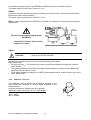
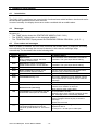
Installation precautions
The centrifuge is designed to be safe under the following conditions:
- Indoor use
- Altitude up to 2000m
- Temperature: from 5°C to 40°C
- Maximum relative humidity 80% (for temperature up to 31 °C)
- Mains supply voltage fluctuation up to ± 10% of the nominal voltage
Incorrect installation will affect safety and equipment performances.
REFMERGEFORMATThe machine must be installed in a dust and non corrosive environment.
1. The Bench top must be rigid, sufficiently strong and levelled.
2. 300 mm of free space gap must be left on each side of the machine, behind to ensure the
proper ventilation.
Fig. 1
The centrifuge could move as a result of rotor imbalance, rotor disruption or drive
failure. To avoid dangerous consequences a safety envelope clearance around the
unit must be respected.
CL30 / CL31 Multispeed Service Manual 11290092
-7-
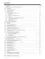
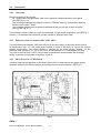
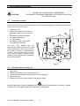
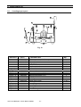
3.4
Component layout
Fig. 2
g
h
i
j
c Inlet appliance
d Imbalance sensor
e Asynchronous motor
f Centrifugation chamber
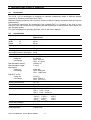
3.5
Lid lock solenoid
Display assembly + keyboard
µP +PWR board
Gas spring
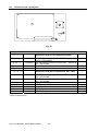
Mains front-end rack
Fig. 3
g Protective conductor terminal
i Mains filter
c Appliance inlet and fuses holder
d Terminal block Fast-on
f Mains transformer
CL30 / CL31 Multispeed Service Manual 11290092
-8-
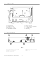
3.6
Functional principles
The microprocessor system controlling the CL30 / CL31 centrifuges ensures the following
functions:
Operator interface management
The operator interface, composed of a LED display and a keyboard, enables programming of the
centrifugation parameters and visualisation of operating conditions in real time
Rotation speed servo-control management
From a tachometer signal, the microprocessor calculates in real time the controls to be applied to
the power components to perform as programmed :
- rotor type identification (maximum speed restriction)
- acceleration and braking profiles
- rotating speed/g-force
- time
Management of the safety devices
The control system manages all the safety devices:
- lid locking system
- imbalance detection system
- zero speed detection system
- motor over-temperature detection system
- over-speed control
Fig. 4
CL30 / CL31 Multispeed Service Manual 11290092
-9-
3.7
Management of the induction motor
3.7.1
Introduction
The CL30 / CL31 centrifuges is equipped with an asynchronous 3 phase induction motor.
During operation, the control electronics generates a system of sinusoidal 3 phase voltages,
variable in amplitude and frequency.
During the braking phase, the energy generated by the motor is dissipated through a resistor.
3.7.2
The motor
It is an AC Induction Motor, called squirrel cage motor, is
comprised of a simple cage-like rotor and a stator
containing three windings. The changing field produced by
the AC line current in the stator induces a current in the
rotor which interacts with the field and causes the rotor to
rotate. No brushes are necessary in this design. The base
speed of the AC motor is determined by the number of
poles built into the stator windings and the frequency of the
AC input voltage. Variable speed control of an AC motor
can be accomplished by increasing or decreasing the input
frequency. A load on the motor causes the motor to "slip" in
proportion to the load.
Fig. 5
3.7.3
Power control operating principle
It consist in a single phase rectifier (in case of 100/120V is used in the voltage doubler
configuration) which converts the AC single phase source in a DC supply. Electrolytic capacitors
are used to provide energy storage for the DC supply
A three phase inverter consisting of six IGBT is used to drive the motor.
Three phase AC is then generated by using sine wave pulse with modulation. The microprocessor
controls the voltages and frequency of the AC output supplied to the motor.
Because AC motor under sine wave excitation are also capable of generating a dynamic brake is
used. When the speed command is reduced in an AC drive, the motor will regenerate. The real
part of the three phase power flows from the motor to the inverter. This results in current flowing
from the inverter into the DC bus capacitors. Because this energy cannot flow back into the AC
supply it must be stored in the capacitors or dissipated through a brake resistor if the voltage will
rise over the defined safety level.
DC
BUS
Fig. 6
CL30 / CL31 Multispeed Service Manual 11290092
- 10 -
3.8
Electronics
3.8.1
Generality
Electronic consist in two boards:
- µP + PWR board (equipped with 16bit micro-controller) located behind the front panel
(see REFFig.2, n.i).
The centrifuge management program is stored “EPROM” memory, configuration data are
stored in non-volatile “RAM”.
- User interface (display and a keyboard) attached directly on the rear of the front panel
(see fig. REFFig. 2.).
The imbalance sensor is fixed on motor counterweight trough elastic suspension (see REFFig. 2,
number ); it detects motor vibrations (usually caused by improper rotor load).
3.8.2
Differences between models (230V-120V-100V)
The main difference between 230V and 120V is on the input stage of the motor power control.
As mentioned in par. 3.7.3 the single phase rectifier, in case of 100/120V, is used in the voltage
doubler configuration. The bridge rectifier is onboard for the 230V version, located on the
electronic rack (see par.5.10 - f) for the 120V. So two different µP + PWR boards are used.
The 100V is derived from a 120V using at step-up transformer located inside the centrifuge.
Wiring connection are reported in Appendix 1 (par 9)
3.8.3
Micro Processor + PWR board
3 distinct areas can be identified on this board. Each of the 3 areas has its own power supply.
Insulation between the different parts is ensured by the use of opto-couplers. (REFFig.7 ).
Fig. 7
AREA 1
CL30 / CL31 Multispeed Service Manual 11290092
- 11 -
It includes the microprocessor, the EPROM, the RAM memory and the backup battery
The power supply for this part of circuits is 5 VDC.
AREA 2
It consist in sensors interface and signal conditioning circuits, including the Opto-couplers which
improve the level of noise immunity
The power supply for this part of circuits is 12 VDC.
Note: In case of replacement of MOTOR or µP+PWR it is mandatory to have the proper jumpers
configuration
The motor with magnetic speed sensor
REQUIRES
Jumper ST2 = Closed (short circuit)
Jumper ST3 = Open
AREA 3
CAUTION :
RISK OF ELECTRIC SHOCK !
Includes all the power circuits and it is directly connected to the mains.
Main function are:
- DC bus (320 VoltDC) , the incoming AC power is rectified and filtered to supply the 3 phases
motor inverter
- The optical insulation (barrier which provides protection against electric shock) between life
parts and microprocessor circuits
- Three phase inverter consisting of six IGBT (one package module) and his control logic circuit.
- Motor brake (IGBT).
3.8.4
Imbalance detector
The imbalance sensor detects the mechanical vibration of the
motor which are converted in electric signal managed by the
microprocessor.
In case of anomalous vibration the run is aborted.
Imbalance sensor connector (J4 µP + PWR board) :
pin 1: Power Supply +12V
pin 2: GND
pin 3: SIGNAL
CL30 / CL31 Multispeed Service Manual 11290092
- 12 -
Fig. 8
3.8.5
Speed sensor
It is a magnetic encoder system based on aluminium disk holding two magnets and an Hall-effect
sensor underneath (see Fig. 13).
Magnetic sensor connector (J7 µP + PWR board) :
pin 1: GND
pin 2: SIGNAL
pin 3: Power Supply +12V (selected by Jumper ST2)
pin 4: Not used
Optical sensor connector (J7 µP + PWR board) :
pin 1: GNDSIGNAL
pin 2: SIGNAL
pin 3: GNDVcc (selected by Jumper ST3)
pin 4: Photo-diode Supply
CL30 / CL31 Multispeed Service Manual 11290092
- 13 -
3.8.6
Inputs – Outputs connection
230V version
Fig. 9
CL30 / CL31 Multispeed Service Manual 11290092
- 14 -
120V version
Fig. 10
CL30 / CL31 Multispeed Service Manual 11290092
- 15 -
4
DIAGNOSTICS AND REPAIRS
4.1
Introduction
The CL30 / CL31 centrifuges has some built-in functional tests which facilitate checks such as for
the tachometer generator and lid lock solenoid.
In case of anomaly the display shows error codes combined with an audible alarm.
4.2
Messages
At power on:
- The “TIME” display shows the CENTRIFUGE MODEL (CL30 / CL31)
- The “SPEED” display lights all the segments (88888).
- The “TEMPERATURE” display shows the PROGARM -EPROM REVISION ( A, B, C….).
4.3
Error codes and messages
When a problem is detected an error code (combined with audible alarm) is displayed. According
to the severity of the anomaly the run can be aborted, in this case the centrifuge stops
automatically. For the details refer to the following table:
CODES
REASON
COMMENTS/EXIT
E 01
Speed = zero
During rotation the speed has been
suddenly measured zero
The information from tachometer is considered
unreliable. The cycle stops without braking.
E 02
Speed error. Values of successive
speed measurements are too different
The information from tachometer is considered
unreliable. The cycle stops without braking.
E 03
E 04
-Rotor is spinning. At power on the
motor has been found in rotation.
-The lid can be open when rotor speed is zero.
Press any key to clean the message.
E 05
E 06
-Lid unlocked during a run
E 07
E 08
-Motor over-temperature (above 130°C)
-Run stops. Operations are not allowed until the
motor speed is zero. Press any key to clear the
message
-The run is interrupted. It is not possible to restart
until the error condition is removed.
Note: wait for motor cooling down.
It is impossible to START.
Close the lid or check if the lid is properly locked,
the message will be automatically cleared
Run stops. Operations are not allowed until the
motor is stopped. Press any key to clear the
message.
Check the rotor load.
Speed digits are blinking + audible alarm
Speed limit are at:
4.100 rpm or 10.000 rpm or 14600 rpm
Solenoid error (reed relay)
LID
IMBAL
____
Lid unlocked. At centrifugation start the
lid has been found open or unlocked
Imbalance detected
Programmed speed is wrong
The programmed speed is over the
maximum speed allowed for the rotor in
use
CL30 / CL31 Multispeed Service Manual 11290092
- 16 -
5
REPLACEMENTS PROCEDURES
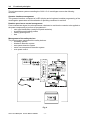
CAUTION:
5.1
BEFORE ANY REPLACEMENT PROCEDURES
DISCONNECT THE MAINS, REMOVING THE POWER CORD FROM
THE CENTRIFUGE !
Front panel removal
Removal of the control panel allows access to many internal components. Follow this procedure to
remove the front control panel:
1. Unplug the unit
2. Remove the 5 screws from the top
and bottom edge of the front panel
d
3. Disconnect the wire harnesses:
- the mains switch wires
- the Flat Cables
- the display power supply cable
- the protective earth wire.
The two Flat Cables can be
disconnected either from the µP+PWR
side (connectors P1 and P2) or from the
front panel: it is better to disconnect all
of them from the same side to avoid
errors during refitting. Disconnect the
display power supply cable (red-black)
from the front panel.
Fig. 11
5.2
1.
2.
3.
4.
5.
Lid replacement (see Fig. 11)
Open the lid
Remove the spring pin from the gas spring c
Unscrew the five screws connecting the lid to the lid hinge
Remove the lid.
Replace the lid in the same fashion, reversing the steps
FIXING SCREWS MUST BE CONSIDERED AS A COMPONENTS OF MECHANICAL SAFETY. CHECK
CAREFULLY THAT THEY HAVE BEEN STRONGLY TIGHTENED !
CL30 / CL31 Multispeed Service Manual 11290092
- 17 -
5.3
1.
2.
3.
4.
5.4
Centrifuge bowl removal (see Fig. 11)
Remove the spring pin from the gas spring c
Remove the bowl gasket e and unscrew the 3 screws from the centrifugation chamber top.
Remove the bowl-motor gasket f.
Remove lifting-up the centrifugation bowl g.
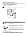
Imbalance sensor replacement (see Fig. 12)
1.
2.
3.
4.
5.
Remove the bowl (see paragraph 5.3)
The detector is located on the motor counterweight
Unscrew the 2 screws and remove the sensor
Unplug the wire harness from the µP+PWR board, J4
Replace the sensor in the same fashion, reversing the
steps
6. Perform the sensor calibration (see par 6.2)
Fig. 12
5.5
Motor replacement (see Fig. 11)
Remove the front panel d (see par. 5.1)
Remove the µP+PWR board
Remove the spring pin from the gas spring c
Remove the bowl gasket e and unscrew the 3 screws from the centrifugation chamber top.
Remove the bowl-motor gasket f.
Remove lifting-up the centrifugation bowl g.
Disconnect the motor wire harnesses h:
- Encoder (J7, µP+PWR board),
- Imbalance sensor (J4 , µP+PWR board)
- Temperature sensor (J8 , µP+PWR board)
- Motor windings (from the contactor)
8. Unscrew the motor fixing screw i located on the centrifuge basement plate
9. Unscrew the 4 screws (Allen key, number 4) to separate the motor from the counterweight .
10. Lift the motor up j
11. Replace the motor in the same fashion, reversing the steps.
1.
2.
3.
4.
5.
6.
7.
Check jumpers ST2 and ST3 (on µP+PWR board), as described in par 3.8.3
Check the rotation direction of the motor. IT MUST BE COUNTERCLOCKWISE
CL30 / CL31 Multispeed Service Manual 11290092
- 18 -
5.6
Speed sensor and shock absorbers replacement (see fig.13)
1. Remove the bottom flange { unscrewing the 5
Phillips screws |
2. Remove the encoder disk unscrewing the screw
~ and the elastic washer
3. Remove the Hall effect sensor removing the 3
screws (10,11,12)
4. Unscrew the 5 shock absorbers }
5. Remove the flange unscrewing the 3 screws
6. Replace the flange and the shock absorbers
reversing the steps
7. Replace the sensor reversing the steps
8. Replace the encoder disk reversing the steps
Screws | ~ (10) must glued using
“Loctite 243”
Fig. 13
CL30 / CL31 Multispeed Service Manual 11290092
- 19 -
5.7
Lid latch assembly
The latch assembly consists of the handle, two latches, 2 switches, a linkage, a locking solenoid
and a reed relay. The cover strikers engages the latches, and when the latch is locked in the
closed position disengage the two switches. The solenoid when is not activated locks the linkage
movement. The switch senses the status of the cover (open, closed), the reed relay senses if the
handle (and the linkage) is locked.
5.8
Replacement of the lid latch assembly
1. Open the lid.
- Remove the front panel unscrewing the five screws (see Fig. 11) and disconnect:
- the mains switch wires
- the Flat Cables
- the display power supply cable
- the protective earth wire.
2. Disconnect the lid latches assembly from the µP+PWR board (J10).
3. Unscrew the four Phillips screws c.
4. Remove the lid lock mechanism support
5. Reassemble (reversing the steps) with the new lid latch ensuring the alignment to get the
proper latching
Fig. 14
c
d
e
f
g
Fixing Phillips screws
Solenoid micro-switch
Lid micro-switches
Solenoid
Lid handle
CL30 / CL31 Multispeed Service Manual 11290092
- 20 -
5.9
Replacement of lid latch spare parts
Fig. 15
5.9.1
1.
2.
3.
4.
5.
Micro-switches replacement { & |
Disconnect the Fast-on connectors
Remove the two screws that secure the switch in place
Reposition the new switch securing it with the screws
Connect the Fast-on connectors
Test the lid latch (use a multimeter to measure resistance across the switch leads)
- Switch should read open, when the cover is open (closed, when the cover is closed)
- Switch should read open, when the cover is open (closed, when the cover is closed)
- The reed relay should read closed when the solenoid is activated
5.9.2
Latch replacement
1. Remove the lid latch assembly as described in par 5.7
2. Extract the Quicklock Benzing .
3. Unscrew the nut .
4. Extract the screw
5. Unscrew the nut .
6. Remove the cam
7. Unscrew the nut underneath the cam
8. Extract the screw
9. Remove the latch
10. Replace the latch in the same fashion, reversing the steps
5.9.3
1.
2.
3.
4.
Remove the two plastic screws
Unsolder the wire harness
Replace the sensor reversing the steps
Test the reed relay (use a multimeter to measure resistance across the sensor)
- The reed relay should read open when lid is open (and the unit is not powered)
- The reed relay should read closed when the solenoid is activated (during centrifugation)
5.9.4
1.
2.
3.
4.
5.
6.
Reed relay (13)
Solenoid (14)
Remove the lid latch assembly as described in 5.7
Disconnect, cutting, the wiring to the solenoid
Unscrew the two fixing screws (latches side)
Slide the locking plunger out
Replace the new solenoid reversing the steps
Verify that the locking plunger is moving freely
CL30 / CL31 Multispeed Service Manual 11290092
- 21 -
5.10
Electronic rack and Mains front-end rack removal (see Fig. 16)
On the Electronic rack are located the µP+PWR board, the motor contactor, and the brake resistor
(behind the µP board). Remove the µP board to access the brake resistor.
On the mains front-end rack are located the mains inlet socket with fuses, the line filter, the
terminal block and the mains transformer. To replace one of those components the rack must be
removed.
f
c
e
Fig. 16
1.
2.
3.
4.
5.
Remove the front panel (see par 5.1 )
Disconnect the wire harness to the contactor f
Disconnect all cable µP+PWR board and the protective earth wire
Remove the electronic rack unscrewing the 4 screws c located on the bottom of the centrifuge
Unscrew the Mains front-end rack (2 screws d on the rear panel and 2 screws e located on
the bottom of the centrifuge)
6. Slide out the Mains front-end rack
5.11
Gas spring replacement
1.
2.
3.
4.
5.
Remove the front panel (see par 5.1)
Remove the centrifuge bowl (see par 5.3)
Remove the Electronic rack (see par 5.10)
Remove the Mains front-end rack (see par 5.10)
Remove the gas spring unscrewing the bolt located inside the centrifuge underneath the
protective ring
6. Replace the gas spring reversing the steps
CL30 / CL31 Multispeed Service Manual 11290092
- 22 -
5.12
1.
2.
3.
4.
Micro Processor + PWR board replacement
Remove the front panel (see par 5.1)
Disconnect all cables and wire harnesses from the board:
Remove the board unscrew the 5 nuts.
Replace the board reversing the steps
Don’ t forget the plastic insulation foil (Mylar®) between the chassis and the board.
Fig. 17
5.13
EPROM replacement
It is not required to remove the P+PWR board for the EPROM replacement
ATTENTION
STATIC SENSITIVE.
Proper handling and grounding precaution required
FOR EPROM REPLACEMENT USE ONLY THE SUITABLE
EXTRACTOR !
DURING REPLACEMENT OPERATION KEEP THE EPROM
PARALLEL TO THE SOCKET
INSERT THE NEW EPROM KEEPING THE KEY (SLOT) TOWARDS
THE MICROPROCESSOR, ALWAYS USING THE EXTRACTOR
1.
2.
3.
4.
Unplug the unit
Remove the front panel (see par 4.1)
Replace the EPROM
Perform the Memory Reset and the Imbalance calibration as described in par. 6
CL30 / CL31 Multispeed Service Manual 11290092
- 23 -
6
DIAGNOSTIC AND CALIBRATION PROGRAM
The centrifuge has a built-in diagnostic program which can be accessed by pressing a
combination of buttons at power on.
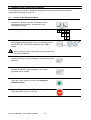
6.1
Access to the Diagnostic Menu
1. At power-on, while the buzzer is activated press
simultaneously the buttons “acceleration” and
“deceleration” ramps
2.
The display will show
0 0
I
t
0
3. Memory Reset
Keep pressed simultaneously (3 sec) the buttons “Pulse”
and SPEED V . The default imbalance level, 350, is
loaded
After a memory reset is mandatory to proceed with the
imbalance calibration
4. Solenoid test
Pressing the button “user’s program 2” the solenoid will be
powered
5. User’s programs reset
Pressing the button “user’s program 4” the User’s
programs will be cleared
6. Imbalance calibration menu
Press the “Start” button to access the Imbalance
calibration menu
7. Exit from Diagnostic and calibration Program
Press the button “Stop” to exit from
CL30 / CL31 Multispeed Service Manual 11290092
- 24 -
AND
6.2
Imbalance Calibration
1. At power-on, while the buzzer is activated, press
simultaneously the buttons “acceleration” and “deceleration”
2. The display will show
0 0
I
t
0
3. Second menu
Press the “Start” button to access the Imbalance
calibration menu
4. The display will show
00 0
5. Install the rotor T40 (unloaded) and press the “Pulse”
button. The first calibration cycle (2500rpm, 50 sec) will
start.
The rotor must be balanced. The difference in weight
between buckets should be maximum ± 0,5 grams
6. At the end of the run the imbalance level measured is
displayed.
For a balanced rotor the value detected shall be
< 200
If the value is > 200 and the rotor is balanced the sensor could
be defective
7. Load bucket n° 1 with the calibrated weight (17 gramsMylar)
8. Press the pulse button, whe secon calibration cycle will start
(2500rpm, 50 sec).
At the end of the run the imbalance level detected will be
displayed.
The imbalance level must be between
300 and 700
9. Exit from Diagnostic and calibration Program
Press the button “Stop” to exit from
CL30 / CL31 Multispeed Service Manual 11290092
- 25 -
20 0
--
7
MOTOR VERIFICATIONS
7.1
Motor checking
Simple electrical tests suggested to verify the status of the motor, (use a multimeter to measure
resistance across the motor windings).
Check :
1. Electrical continuity between all the two phases combinations.
In case of open circuit the motor will not run
2. Resistance of two phases values must be 7Ω ± 20%
3. The difference between two phases should not differ more than ± 0.2Ω);
If not the motor doesn’t run smoothly (jerks)
7.2
Centering device assembly
Verify:
1. the correct washers sequence
Motor shaft
2. the free movements of the washers
O-Ring
3. the washers must be properly greased.
Centering device
Washers sequence:
n.1 Flat washer
n.2 Spring washers
n.1 Flat washer
n.2 Spring washers
n.1 Flat washer
n.2 Spring washers
n.1 Flat washer
Fig. 18
CL30 / CL31 Multispeed Service Manual 11290092
- 26 -
8
SPARE PARTS LIST
8.1
Centrifuge spare parts
Fig. 19
Reference
See Fig. 19
Fig 19 - c
Fig 19 - d
Fig 19 - d
Fig 19 - e
Fig 19 - f
Fig 19 - g
Fig 19 - h
Fig 19 - i
Fig 19 - j
CAT n.
DESCRIPTION
25535010
11202979
85480453
86000692
86003202
86005398
Tool to open the unit without power
Tool to remove the rotor
Magnetic plate
Drain Tube
Cap for drain tube
Grease for buckets
89000838
39903281
39903283
89002890
11250217
85240195
11200717
26962012
89002039
89000943
89000839
Mains switch
Keypad membrane CL30
Keypad membrane CL31
Display board
Lid Assy
Latch strike (hook)
Lid hinge
Gas spring
Centrifugation bowl chamber
Bowl gasket
Bowl-Motor gasket
CL30 / CL31 Multispeed Service Manual 11290092
- 27 -
Qty.
1
1
1
1
1
1
1
1
1
1
1
1 of 2
1
1
1
1
1
8.2
Electronic rack spare parts
Fig. 20
See Fig. 20
c+d+e+f
Fig 20 - c
Fig. 20 - c
Fig 20 - d
Fig 20 - f
Electronic rack ( kit of components 230V)
89003436* µP+PWR board (230V) NEW MOTOR – (tested)
for Sn > 305100385
89003463* µP+PWR board (230V) OLD MOTOR – (tested) for
Sn < 305100385
86004585 Contactor (230V)
86001432 Brake resistor
c+d+e+f
Fig 20 - c
Fig. 20- c
Fig 20 - e
Fig 20 - d
Fig 20 - f
Electronic rack (kit of components 100- 120V)
89003437* µP+PWR board (120V) NEW MOTOR - (tested) for
Sn > 305100385
89003462* µP+PWR board (120V) OLD MOTOR - (tested) for
Sn < 305100385
86004598 Bridge rectifier (120V)
86004586 Contactor ( (120V)
86001432 Brake resistor
89003532 EPROM programmed CL30
11250210 EPROM programmed CL31
* doesn’t contain eprom
CL30 / CL31 Multispeed Service Manual 11290092
- 28 -
1
1
1
1
1
1
1
1
1
1
1
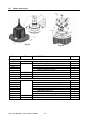
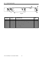
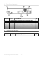
8.3
Motor spare parts
Fig. 21
Reference
CAT n.
Fig. 22
DESCRIPTION
Qty.
See Fig. 21
Fig. 21
Fig.21 - efgh
Fig.21 - e
Fig.21 - f
Fig.21 - g
Fig.21 - h
Fig.21 - d
Fig.21 - i
11250202
11250172
39902739
11200508
86005398
1
Motor assy
Shaft accessory Kit
Flat washer (thickness 0.5)
Spring washer
Plastic Centering device
O-Ring
Imbalance detector
Motor Counterweight
Grease
4
6
1
1
1
1
1
Shock Absorbers kit
Shock absorbers bottom flange
Shock absorbers Ø15x15 f-f 55ShA
Magnetic disk assy
Shock absorbers upper flange
Hall effect sensor kit
Set of screws
Grease
Shock absorbers Ø15x15 f-f 55ShA (set of 5)
Hall effect sensor kit
1
1
5
1
1
1
1
1
1
See Fig. 22
Fig.22
Fig.22 - c
Fig.22 - e
Fig.22 - h
Fig.22 - i
Fig.22 - k
11250204
Fig.22 - e
Fig.22 - k
11250203
11250212
CL30 / CL31 Multispeed Service Manual 11290092
- 29 -
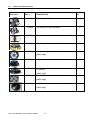
8.4
Lid latch spare parts
h
i
d
Fig. 23
Reference
CAT n.
DESCRIPTION
Fig. 23
Fig. 23 - c
Fig. 23 - d
Fig. 23 - e
Fig. 23 - f
Fig. 23 - f
Fig. 23 - g
Fig. 23 - h
Fig. 23 - i
11202913
86001406
11201185
39900043
85140275
85440187
11250207
11201156
85440203
Lid Latch assy
Lid micro-switch
Latch
Solenoid switch (Reed Relay)
Solenoid
Solenoid Spring
Spring
Locking cam
Handle
CL30 / CL31 Multispeed Service Manual 11290092
- 30 -
Qty.
1
1
2
1
1
1
1
2
1
8.5
Mains front-end spare parts
Fig. 24
Reference
CAT n.
DESCRIPTION
Qty.
c+f+i
39902981 Mains front-end rack (kit of components 230V)
1
Fig. 24 - f
Fig. 24 - i
Fig. 24 - c
c+f+i
Fig. 24 - f
Fig. 24 - i
Fig. 24 - c
86004803 Toroidal transformer 230Volt
86003248 Line filter 230Volt
86000614 Mains inlet and fuse holder
39902587 Mains front-end rack (kit of components 120V)
39903078 Toroidal transformer 120Volt
86003256 Line filter 120Volt
86000614 Mains inlet and fuse holder
1
1
1
1
1
1
1
8.6
Transformers for 100V version
Reference
CAT n.
11250205
DESCRIPTION
Transformer 100V 50-60Hz
CL30 / CL31 Multispeed Service Manual 11290092
- 31 -
Qty.
1
8.7
Rotors and Accessories
Reference
CAT n.
DESCRIPTION
11210435
T41 Swing-Out Rotor
1
S41 Swing-Out Rotor (4x200ml)
1
11175750
T20 Microtiter Plate Rotor for 2 x 3 Plates, 1157xg
1
11175755
AC15.4 Angle Rotor, 30 x 15ml (17.5x100mm)
1
11175756
AC100.10 Angle Rotor, 6 x 100ml (38x101mm)
1
11210246
Qty.
(CL31 only)
11175754
AC50.10 Angle Rotor, 6 x 50ml
1
11175741
AC2.14 Sealed Angle Rotor, 24 x 1.5-2ml
(11x39mm)
1
11175743
(CL31 only)
DC6.11 Drum Rotor, 6 Micro tubes Racks
1
(CL31 only)
11210351
AC2.13, Sealed FiberLite Angle Rotor, 48 x 1.5ml
(CL31 only)
CL30 / CL31 Multispeed Service Manual 11290092
- 32 -
1
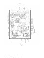
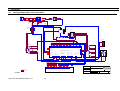
9
9.1
APPENDIX 1
Wiring diagram 230 V version 50-60Hz
2x4AT fuses
Main switch
Line filter 3A
Brown
903208/1
L
LOAD1
Brown
E
902574/4
Blue
N
903208/1
Yellow/green
903208/2
LOAD2
Brown
Brown
Blue
Blue
Blue
902574/1
902574/3
902574/5
Chassis
902574/2
Display board
902574/6
Main earth
(rack)
Front panel
Basement
Blue
Blue
903205
red
Brow
n
902573
902564
902558
Rack
Terminal
Block
12
Encoder
12
34
34
Blu
blue
e
Br
Brow
own
n
K1
902561
Thermoswitch
Contactor
AC Motor
SW19
LC1K0610M7
Imbalance
sensor
blue
Blue
1L1
2T1
3L2
4T2
green
903208/3
903212
Green
red
903212
Red
5L3
903212
6T3
902564
90
25
90 77
25
77
SW17
brown
Brown
902573
100n + 47ohm
(Rifa - PMR 209 MC)
blue
902573
Brake resistor
yellow
902577
2625242322212019181716151413121110
987654321
123456789
1011121314151617181920212223242526
P1
18V
5
4
3
2
1
230V
P2
keyboard and pilot leds
123
10.5V AC
Bla
Re
ck
d
1234
J15
Display
100 ohm
Yel
Yel
low
low
ReRe
dd
CMC34
TRANSFORMER
3
2
1
Orange
J1
Reed
switch
J2
Motor +15V
Red
12VDC
J3 (not used)
Imbalance
J4 sensor
AC J14
Motor
CPU and Power control _ 230V
100W
yellow
123
10,5V
white
green
red
902566
5
4
3
2
1
Black
Blue
Power rectifier
Solenoid
Green
Red
1
Black
23V
4
white
4
3
2
1
J5
(not used)
Encoder
J7
Motor
thermoswitch
J8
+12V
Lid switch, solenoid
switch and solenoid
command
J10
J9
Compressor
command
(not used)
Line
power
J11
J12
J13
brake
resistors
1
2
+
Ext Power
rectifier
J16
3
white
blue
red
4321
GrWh
ReGreeite
d eyn
321
21
blabla
ckck
bla
bla
ckck
109 8 7 6 5 4 3 2 1
yell
whi
whi bla bla
owred tete ck ck
321
21
blubro
e wn
2
-
Lid switch
bla
ck
321
902554
blubla
Re
e ckd
902577
902575
902565
Flat Cable
902559
Flat Cable
902559
Bla
Re
ck
d
123456789
1011121314151617181920212223242526
123456789
1011121314151617181920212223242526
12
Drawn by
A. Frollo
P1
Eyelet
P2
Display and Keyboard
Verified by
Model
220-230V 50-60 Hz
Denomination
General wiring diagram
A. Frollo
Faston
Braided sleeve
Approved by
Sheet
of
1
Size
EMBED
CL30 / CL31 Service Manual 902971 rev.1
Document Number
1
Date
Wednesday, October 12, 2005
A2
902587
The reproduction in whole or part of this design, is forbidden. All rights are reserved to Jouan Italia S.r.l.
- 33 -
Rev
B
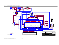
9.2
Wiring diagram 120V version 60Hz
2x6.3AT fuses
Line filter
Brown
903208/1
L
Main switch
LOAD1
Brown
E
902574/4
Blue
N
903208/1
903208/2
LOAD2
Yellow/green
Brown
Brown
Blue
Blue
Blue
902574/1
902574/3
Chassis
902574/5
902574/2
Display board
902574/6
Main earth
(rack)
Front panel
Basement
Blue
Blue
903205
red
Brow
n
902573
902564
902558
Rack
Terminal
Block
12
Encoder
12
34
34
Blu
blue
e
Br
Brow
own
n
K1
902561
Thermoswitch
Contactor
AC Motor
SW19
LC1K0610F7
Imbalance
sensor
blue
Blue
1L1
2T1
3L2
4T2
green
903208/3
903212
Green
red
903212
Red
5L3
903212
6T3
902564
90
25
90 77
25
77
SW17
brown
Brown
902573
100n + 47ohm
(Rifa - PMR 209 MC)
blue
902573
Brake resistor
yellow
902577
2625242322212019181716151413121110
987654321
123456789
P1
18V
5
4
3
2
1
120V
1011121314151617181920212223242526
P2
10.5V AC
Bla
Re
ck
d
1234
J15
Display
keyboard and pilot leds
123
100 ohm
Yel
Yel
low
low
ReRe
dd
CMC35
TRANSFORMER
3
2
1
Orange
J1
J2
Motor +15V
12VDC
Reed
switch
Red
J3 (not used)
Imbalance
J4 sensor
AC J14
Motor
CPU and Power control 120V
100W
yellow
123
10,5V
white
green
red
902566
5
4
3
2
1
Black
Blue
Power rectifier
Solenoid
Green
Red
1
Black
23V
4
white
4
3
2
1
J5
(not used)
Encoder
J7
Motor
thermoswitch
J8
+12V
Lid switch, solenoid
switch and solenoid
command
J10
J9
Compressor
command
(not used)
Line
power
J11
J12
J13
brake
resistors
1
2
+
Lid switch
Ext Power
rectifier
J16
321
21
blabla
ckck
blabla
ckck
109 8 7 6 5 4 3 2 1
yell
whi
whi bla bla
owred te te ck ck
321
21
blubro
e wn
2
white
red
4321
GrWh
ReGreeite
d eyn
-
3
blue
bla
ck
321
902554
blublaRe
e ckd
902577
902575
902565
Flat Cable
902559
Flat Cable
902559
Bla
Re
ck
d
123456789
1011121314151617181920212223242526
123456789
1011121314151617181920212223242526
12
Drawn by
Model
120V 60 Hz
A. Frollo
P1
Eyelet
P2
Verified by
Display and Keyboard
Denomination
General wiring diagram
A. Frollo
Faston
Braided sleeve
Approved by
Sheet
of
1
Size
EMBED
CL30 / CL31 Service Manual 902971 rev.1
Document Number
1
Date
A2
Rev
902578
Wednesday, October 12, 2005
The reproduction in whole or part of this design, is forbidden. All rights are reserved to Jouan Italia S.r.l.
- 34 -
B
9.3
Wiring diagram 100V version 50-60Hz
2x6.3AT fuses
Line filter
Brown
903208/1
L
LOAD1
Main switch
Brown
Brown
Blue
Blue
903205
E
902574/4
Brown
903208/2
AUTOFORMER 660VA
120V
903205
Blue
903208/1
N
Yellow/gree
n
902574/5
LOAD2
Blue
brown
100V
902574/1
902574/3
blue
Chassis
0V
0V
902574/2
Display board
902574/6
Main earth
(rack)
blu
e
Front panel
red
Basement
903205
Blu
e
Blu
e
red
Bro
wn
1 2
1 2
902573
902564
902558
Encoder
Rack
Terminal
Block
3 4
3 4
K1
Blublu
e e
902561
Bro
Bro
wnwn
Thermoswitch
Contactor
AC Motor
SW19
LC1K0610F
7
Imbalance
sensor
blue
Blue
1L1
2T1
3L2
4T2
5L3
6T3
green
903208/3
red
SW17
brown
903212
Red
902564
902
577
903212
Green
Brown
902573
903212
100n +
47ohm
902
577
(Rifa - PMR 209 MC)
blue
902573
Brake resistor
yellow
902577
100 ohm
YelYel
low
low
ReRe
d d
26252423222120191817161514131211109 8 7 6 5 4 3 2 1
1 2 3 4 5 6 7 8 9 1011121314151617181920212223242526
P1
P2
keyboard and pilot leds
Display
120V
1 2 3 4
J15
18V
5
4
3
2
1
1 2 3
10.5V AC
Bla
Re
ck
d
3
2
1
Orang
e
1 2 3
J1
J2
Motor +15V
12VDC
Imbalance
J4 sensor
AC
J14
Motor
CPU and Power control 120V
100W
yellow
Reed
switch
Red
J3 (not used)
10,5V
white
green
red
902566
5
4
3
2
1
Black
Blue
Power rectifier
Solenoid
Green
1
Red
Black
23V
4
white
4
3
2
1
LOW VOLTAGE TRANSFORMER
(CMC35)
(not used)
Lid switch, solenoid
switch and solenoid
command
J5
Encoder
J7
Motor
thermoswitch
J8
Compressor
command
(not used)
+12V
Line
power
J10
J9
J11
J12
brake
resistors
J13
1
2
GrWh
ReGreeite
d eyn
3 2 1
blabla
ckck
2 1
109 8 7 6 5 4 3 2 1
blabla
ckck
yell
owred
3 2 1
2 1
blubro
e wn
whi
whi bla bla
te te ck ck
-
Lid switch
Ext Power
rectifier
J16
2
3
white
red
4 3 2 1
+
3 2 1
blu
e
bla
ck
902554
blublaRe
e ckd
902577
902575
902565
Flat Cable
902559
Flat Cable
902559
Bla
Re
ck
d
1 2 3 4 5 6 7 8 9 1011121314151617181920212223242526
1 2 3 4 5 6 7 8 9 1011121314151617181920212223242526
1 2
Drawn by
A. Frollo
9xxxxx
Document number
Eyelet
Display and Keyboard
Model
100V 50/60 Hz
Verified
by
A. Frollo
Denominatio
n
Approved
by
Sheet
General schematic
Faston
Braided sleeve
of
1
Size
Document
Number
1
Date
Thursday, September 22,
2005
A2
Rev
903203
The reproduction in whole or part of this design, is forbidden. All rights are reserved to Jouan Italia S.r.l.
CL30 / CL31 Service Manual 902971 rev.1
- 35 -
A