1
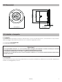
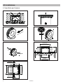
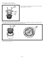
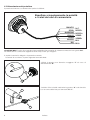
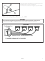
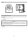
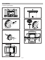
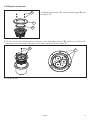
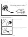
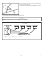
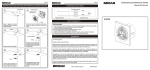
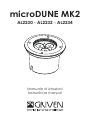
microDUNE MK2
AL2230 - AL2232 - AL2234
Manuale di istruzioni
Instructions manual
INDICE
1.0 Introduzione...................................................................................................................................4
1.1 Informazioni di sicurezza.........................................................................................................................................4
1.1.1 Protezione da scariche elettriche ..................................................................................................................4
1.1.2 Installazione .....................................................................................................................................................4
1.1.3 Protezione dagli incendi .................................................................................................................................4
1.1.4 Protezione da solidi e liquidi...........................................................................................................................4
1.2 Normative .................................................................................................................................................................4
2.0 Dimensioni .....................................................................................................................................5
3.0 Imballo e trasporto .......................................................................................................................5
3.1 Imballo......................................................................................................................................................................5
3.2 Trasporto ...................................................................................................................................................................5
4.0 Installazione ..................................................................................................................................6
4.1 Specifiche per l’incasso ..........................................................................................................................................6
4.2 Fissaggio nella cassaforma ....................................................................................................................................7
4.3 Alimentazione del proiettore..................................................................................................................................8
4.4 Connessione del proiettore al Transformer Box AL1861.......................................................................................9
5.0 Manutenzione .............................................................................................................................10
5.1 Pulizia del proiettore ..............................................................................................................................................10
5.2 Controlli periodici ..................................................................................................................................................10
6.0 Parti di ricambio..........................................................................................................................10
7.0 Smaltimento dell ‘apparecchiatura..........................................................................................10
8.0 Specifiche tecniche ...................................................................................................................11
INDEX
1.0 Introduction .................................................................................................................................12
1.1 Safety information..................................................................................................................................................12
1.1.1 Protecting against electric shock ................................................................................................................12
1.1.2 Installation ......................................................................................................................................................12
1.1.3 Protection against burns and fire .................................................................................................................12
1.1.4 Weather protection........................................................................................................................................12
1.2 Compliance ...........................................................................................................................................................12
2.0 Size ...............................................................................................................................................13
3.0 Packaging and transpor ............................................................................................................13
3.1 Packaging ..............................................................................................................................................................13
3.2 Transport .................................................................................................................................................................13
4.0 Installation ...................................................................................................................................14
4.1 Build in specifications............................................................................................................................................14
4.2 Fitting the framework.............................................................................................................................................15
4.3 Powering up the unit..............................................................................................................................................16
4.4 Connection from unit and transformer box AL1861 ...........................................................................................17
5.0 Maintenance...............................................................................................................................18
5.1 Cleaning the unit ...................................................................................................................................................18
5.2 Regular checks ......................................................................................................................................................18
6.0 Spare parts ..................................................................................................................................18
7.0 Disposal........................................................................................................................................18
8.0 Technical specifications ............................................................................................................19
.
1.0 Introduzione
1.1 Informazioni di sicurezza
Attenzione!
Questo prodotto è adatto solo ad un uso professionale, non ad un uso domestico.
1.1.1 Protezione da scariche elettriche
• Togliere l’alimentazione prima di effettuare qualsiasi operazione all’interno dell’apparecchiatura.
• Prima di connettere l’apparecchio all’alimentatore, verificate la compatibilità di tensione e corrente.
• Non maneggiate il prodotto con mani bagnate o in presenza di acqua.
• Controllate periodicamente che il cavo di alimentazione non sia schiacciato o danneggiato.
• Rivolgersi ad un tecnico qualificato per qualsiasi operazione di manutenzione ordinaria non descritta nel
presente manuale.
•
III
Apparecchio di classe terza. Utilizza tensioni inferiori ai 50 Volts. Esclude e vieta la messa a terra.
1.1.2 Installazione
• Le operazioni di installazione dell ‘apparecchiatura devono essere eseguite da personale competente e
qualificato.
1.1.3 Protezione dagli incendi
•
Idoneo ad essere installato su superfici normalmente infiammabili.
1.1.4 Protezione da solidi e liquidi
Il proiettore rientra nella classificazione di apparecchio con grado di protezione IP67.
•
Sostituite gli schermi di protezione danneggiati utilizzando ricambi GRIVEN.
1.2 Normative
• L’apparecchio soddisfa i requisiti della normativa EN60598-1.
• L’apparecchio soddisfa i requisiti della direttiva 2002/95/CE (RoHS).
4
Italiano
Ø114mm
4.5”
Ø136mm
5.35”
2.0 Dimensioni
14mm
0.6”
Ø102mm
4.0”
Ø151,50mm
6.0”
6mm
0.2”
3.0 Imballo e trasporto
3.1 Imballo
Controllate attentamente il contenuto del cartone e, in caso di danni al prodotto, contattate il Vs. trasportatore.
Nell’imballaggio del presente proiettore sono contenuti i seguenti prodotti:
n° 1 proiettore microDUNE MK2
n° 1 manuale di istruzioni
Attenzione!
• La responsabilità di Griven S.r.l. cessa all’atto della consegna del materiale al vettore: reclami per eventuali
danni dovuti al trasporto dovranno essere indirizzati direttamente al corriere.
• Si accettano reclami entro e non oltre i 7 giorni dal ricevimento della merce.
• Eventuali resi di materiale dovranno essere autorizzati da Griven S.r.l. ed inviati completi della documentazione
fiscale necessaria.
3.2 Trasporto
Si raccomanda di trasportare l’apparecchiatura con estrema attenzione, utilizzando il suo imballo originale per
evitare di danneggiare il prodotto.
Italiano
5
4.0 Installazione
4.1 Specifiche per l’incasso
Max 3000 Kg
x
Ma
K
20
h
m/
MATERIALE DI DRENAGGIO
Ø114
Ø136
Ø12mm
Ø152mm
Ø114
Ø136
Ø12mm
96mm
6
Italiano
Ø12mm
Ø12mm
96mm
Ø152mm
4.2 Fissaggio nella cassaforma
1. Aprite il proiettore allentando le viti “A” e rimuovete
la flangia “B” e il vetro “C”.
A
B
C
2. Fissate il proiettore alla cassaforma utilizzando le viti autofilettanti “D” che troverete nella
cassaforma. Le viti devono essere inserite nei fori “E”.
D
E
3. Richiudete il proiettore.
Italiano
7
4.3 Alimentazione del proiettore
Il proiettore funziona con alimentatori per led a 350mA.
Rispettare scrupolosamente la polarità
e i colori dei cavi di connessione.
BIANCO
ROSA
MARRONE
GIALLO
VERDE
GRIGIO
BLU
N.C.
ROSSOROSSO+
VERDEVERDE+
BLUBLU+
microDUNE MK2 è fornito di una guaina termoretraibile che permette di ottenere connessioni con grado IP67.
Per effettuare la connessione seguite le istruzioni riportate qui di seguito.
1. Aprite il sacchetto allegato al presente manuale.
Troverete al suo interno 2 pezzi di guaina termoretraibile.
2. Infilate la guaina con diametro maggiore “F” sul cavo di
alimentazione “G”.
F
G
3. Saldate i fili e isolateli mediante la guaina “H” scaldandola
con un un riscaldatore per termoretraibili “L”.
L
H
8
Italiano
4. Scaldate la guaina “F” utilizzando un riscaldatore per termoretraibili “L” fino al completo restringimento.
La connessione così ottenuta ha in grado di protezione IP67.
L
F
4.4 Connessione del proiettore al Transformer Box AL1861
Attenzione!
• Prima di collegare l’apparecchio assicuratevi che la fornitura elettrica corrisponda a quelle ammesse.
• Le operazioni di cablaggio e collegamento devono essere eseguite da personale qualificato.
micro MK2
Transformer box
AL1861
massimo 50 metri - sezione minima 0.35 mm²
E’ possibile collegare da 1 a 4 proiettori
Italiano
9
5.0 Manutenzione
Per assicurare la massima funzionalità e resa ottica si raccomanda di attenersi alle istruzioni riportate qui di seguito.
Attenzione!
Togliete tensione prima di effettuare qualsiasi operazione sul proiettore.
5.1 Pulizia del proiettore
Il proiettore deve essere pulito regolarmente. La frequenza della pulizia dipende soprattutto dall’ambiente nel
quale l’apparecchiatura funziona, infatti polvere eccessiva, depositi di fumo ed altre scorie riducono le prestazioni ottiche.
• Pulite regolarmente il vetro del proiettore
• Non usare solventi che potrebbero danneggiare le superfici verniciate.
5.2 Controlli periodici
• Controllate i collegamenti elettrici ed in particolare la messa a terra ed il cavo di alimentazione.
• Controllate che il proiettore non sia danneggiato meccanicamente ed eventualmente sostituite le parti deteriorate.
6.0 Parti di ricambio
Tutti i componenti del proiettore sono disponibili come parti di ricambio presso i rivenditori Griven.
Le viste esplose, lo schema elettrico e il diagramma elettronico sono disponibili su richiesta.
Per facilitare il lavoro del centro di assistenza ricordate di specificare il numero di serie ed il modello del proiettore di cui avete richiesto i ricambi.
7.0 Smaltimento dell ‘apparecchiatura
La direttiva Europea 2002/96/CE sui rifiuti di apparecchiature elettroniche (RAEE), prevede che gli apparecchi
illuminanti non debbano essere smaltiti nel normale flusso dei rifiuti solidi urbani. Gli apparecchi dismessi debbono
essere raccolti separatamente per ottimizzare il tasso di recupero e riciclaggio dei materiali che li compongono
ed impedire potenziali danni per la salute e l’ambiente.
Il simbolo del cestino barrato è riportato su tutti i prodotti per ricordare gli obblighi di raccolta
separata.
Per ulteriori informazioni sulla corretta dismissione delle apparecchiature, i detentori potranno rivolgersi al servizio
pubblico preposto o ai rivenditori.
10
Italiano
8.0 Specifiche tecniche
Caratteristiche meccaniche
Altezza . . . . . . . . . . . . . . . . . . . . . . . . . . . . . . . . . . . . . . . . . . . . . . . . . . . . . . . . . . . . . . . . . . . . . . . . . . . . . . . .102mm (4”)
Ø Inferiore . . . . . . . . . . . . . . . . . . . . . . . . . . . . . . . . . . . . . . . . . . . . . . . . . . . . . . . . . . . . . . . . . . . . . . . . . .Ø109mm (4.3”)
Ø Superiore . . . . . . . . . . . . . . . . . . . . . . . . . . . . . . . . . . . . . . . . . . . . . . . . . . . . . . . . . . . . . . . . . . . . . . . . .Ø151.5mm (6”)
Peso . . . . . . . . . . . . . . . . . . . . . . . . . . . . . . . . . . . . . . . . . . . . . . . . . . . . . . . . . . . . . . . . . . . . . . . . . . . . . . . . .1.7Kg (3.7Lbs)
Caratteristiche termiche
Massima temperatura ambiente . . . . . . . . . . . . . . . . . . . . . . . . . . . . . . . . . . . . . . . . . . . . . . . . . . . . . . . . . .40°C (104°F)
Massima temperatura superficiale . . . . . . . . . . . . . . . . . . . . . . . . . . . . . . . . . . . . . . . . . . . . . . . . . . . . . <60°C ( <140°F)
Caratteristiche elettriche
Tensione di alimentazione . . . . . . . . . . . . . . . . . . . . . . . . . . . . . . . . . . . . . . . . . . . . . . . . . . . . . . . . . . . . . . . . . . . .12 Vdc
Corrente nominale . . . . . . . . . . . . . . . . . . . . . . . . . . . . . . . . . . . . . . . . . . . . . . . . . . . . . . . . . . . . . . . . . . . . . 350mA max
Potenza massima . . . . . . . . . . . . . . . . . . . . . . . . . . . . . . . . . . . . . . . . . . . . . . . . . . . . . . . . . . . . . . . . . . . . . . . . . . . . 10.8W
Sorgente luminosa
Tipo sorgente luminosa . . . . . . . . . . . . . . . . . . . . . . . . . . . . . . . . . . . . . . . . . . . . . . . . . . . . . . . . . . . . . 3 Led RGB x 3.6W
Ottica
Sistema ottico . . . . . . . . . . . . . . . . . . . . . . . . . . . . . . . . . . . . . . . . . . . . . . . . . . . . . . . . . . . . . . . . . . . . . . . . . . . . . . A lenti
Ottiche disponibili . . . . . . . . . . . . . . . . . . . . . . . . . . . . . . . . . . . . 12° cod. AL2230 / 28° cod. AL2232/ 40° cod. AL2234
Costruzione
Corpo proiettore . . . . . . . . . . . . . . . . . . . . . . . . . . . . . . . . . . . . . . . . . . . . . . . . . . . . . . . . Acciaio inox / Alluminio / ABS
Trattamento . . . . . . . . . . . . . . . . . . . . . . . . . . . . . . . . . . . . . . . . . . . . . . . . . . . . . . . . . . . . . . . . . . . . . Vernice antigraffio
Fattore di protezione . . . . . . . . . . . . . . . . . . . . . . . . . . . . . . . . . . . . . . . . . . . . . . . . . . . . . . . . . . . . . . . . . . . . . . . . . . . IP67
Italiano
11
1.0 Introduction
1.1 Safety information
Warning!
This unit is suitable for professional use only, not for domestic use.
1.1.1 Protecting against electric shock
• Disconnect the unit from mains supply before servicing it or performing any other action.
• Before connecting the unit to power supplies, verify that operating voltage and current are compatible.
• Do not handle the unit with wet hands or in the presence of water.
• Check regularly that the power supply cable is not damaged or crushed.
• Apply to a qualified technician for any regular maintenance action not described in this manual.
•
III
Class 3 device. It uses operating voltages inferior to 50 Volts. It excludes and forbit ground connection.
1.1.2 Installation
• The unit installation actions must be performed by a qualified staff.
1.1.3 Protection against burns and fire
•
Suitable to be installed onto normally inflammable surfaces.
• The unit is not to be installed in places where the ambient temperature exceeds 40° (104°F).
1.1.4 Weather protection
The unit is classified as device with an IP67 weather protection rate.
•
Replace any damaged shields with original GRIVEN spare parts..
1.2 Compliance
• Product in compliance with EN60598-1.
• Product in compliance with 2002/95/CE (RoHS).
12
English
Ø114mm
4.5”
Ø136mm
5.35”
2.0 Size
14mm
0.6”
Ø102mm
4.0”
Ø151,50mm
6.0”
6mm
0.2”
3.0 Packaging and transport
3.1 Packaging
Check carefully the content of the box and, in case of damage, contact your forwarder immediately.
The following items are included in the box of this unit:
n° 1 microDUNE MK2 unit
n° 1 owner’s manual
Warning!
• Griven S.r.l. liability will cease upon consignment of goods to the forwarder: claims for damage due to transport must be addressed directly to the forwarder.
• Griven S.r.l. will accept claims for broken or missing goods only within seven days of receipt of the goods.
• Returns of equipment will not be accepted without prior authorization granted by Griven S.r.l. and if not duly accompanied by relevant shipping documents.
3.2 Transport
It is recommended to transport the unit with the maximum care, by using its original packing, to avoid to
damage the unit.
English
13
4.0 Installation
4.1 Build in specifications
Max 3000 Kg
x
Ma
K
20
h
m/
DRAINAGE MATERIAL
Ø114
Ø136
Ø12mm
Ø152mm
Ø114
Ø136
Ø12mm
96mm
14
English
Ø12mm
Ø12mm
96mm
Ø152mm
4.2 Fitting the framework
1. Untighten the screws "A", remove the flange "B" and
the glass “C”.
A
B
C
2. Fit the unit to the framework by using the auto-threading screws "D" which you will find attached to the formwork. The screws must be inserted into the holes "E".
D
E
3. Close the unit.
English
15
4.3 Powering up the unit
The unit can operate with standard 350mA led driver.
Polarity and colours correspondence of the
connection cables must be strictly respected.
WHITE
PINK
BROWN
YELLOW
GREEN
GRAY
BLUE
N.C.
REDRED+
GREENGREEN+
BLUEBLUE+
microDUNE MK2 is fitted with heat shrink tube which allow to perform IP67 connections.
To make the connection follow these instructions.
1. Open the bag enclosed yo this manual.
You will find inside two pieces of heat shrink tube.
2. Insert the tube “F” onto the cable “G”.
F
G
3. Solder the wires and isolate it through the heat shrink tube “H”
by using a heater for heat shrink tubes “L”.
L
H
16
English
4. Warm up the tube “F” by using a heater for heat shrink tubes
“L” till the complete shrinkage.
The connection so obtained features an IP67 protection rate.
L
F
4.4 Connection from unit and transformer box AL1861
Warning!
• Before connecting the unit, verify that power supplies features are compatible with the unit features.
• Wiring and connection actions are to be performed by a qualified staff.
micro MK2
Transformer box
AL1861
maximum 50 meters
minimum section 0.35 mm²
Minimum 1 unit - Maximum 4 unit
English
17
5.0 Maintenance
Attention!
Always remove mains power prior to opening up the fixture.
To ensure maximum functionality and light output it is recommended to follow these instructions:
5.1 Cleaning the unit
The unit must be cleaned regularly. Cleaning regularity will depend especially on the environment where the unit
will operate: deposits of dust, smokes or other wastes will reduce the light output performances.
• Clean regularly the glass of the unit.
• Do not use solvents which could damage painted surfaces.
5.2 Regular checks
• Check electrical connections, especially the ground wiring and the power supply cable.
• Check that the unit is not damaged mechanically. Replace those components which have got deteriorated.
6.0 Spare parts
All components of the unit are available as spare parts at Griven dealers.
Exploded views, wiring diagrams, electronic layouts and advertising brochures are available on request.
To make the job of assistance centres easier, specify serial number and model of the unit which spare parts are
requested for.
7.0 Disposal
The European Directive 2002/96/EC on Waste Electrical and Electronic Equipment (WEEE), requires that old
lighting fixtures must not be disposed of the normal unsorted municipal waste stream. Old appliances must be
collected separately in order to optimise the recovery and recycling of the materials they contain and reduce
the impact on human health and the environment.
The crossed out “wheeled bin” symbol on the product reminds you of your obligation, that when you
dispose of the appliance it the must be separately collected.
Consumer should contact their local authority or retailer for information concerning the correct disposal of their
old appliance.
18
English
8.0 Technical specifications
Mechanical features
Height . . . . . . . . . . . . . . . . . . . . . . . . . . . . . . . . . . . . . . . . . . . . . . . . . . . . . . . . . . . . . . . . . . . . . . . . . . . . . . .102mm (4.1”)
Ø Lower . . . . . . . . . . . . . . . . . . . . . . . . . . . . . . . . . . . . . . . . . . . . . . . . . . . . . . . . . . . . . . . . . . . . . . . . . . . .Ø109mm (5.5”)
Ø Higher . . . . . . . . . . . . . . . . . . . . . . . . . . . . . . . . . . . . . . . . . . . . . . . . . . . . . . . . . . . . . . . . . . . . . . . . . . . .Ø151.5mm (6”)
Weight . . . . . . . . . . . . . . . . . . . . . . . . . . . . . . . . . . . . . . . . . . . . . . . . . . . . . . . . . . . . . . . . . . . . . . . . . . . . . . .1.7Kg (3.7Lbs)
Thermal features
Maximum ambient temperature . . . . . . . . . . . . . . . . . . . . . . . . . . . . . . . . . . . . . . . . . . . . . . . . . . . . . . . . . .40°C (104°F)
Maximum surface temperature . . . . . . . . . . . . . . . . . . . . . . . . . . . . . . . . . . . . . . . . . . . . . . . . . . . . . . . . <60°C ( <140°F)
Electrical features
Voltage . . . . . . . . . . . . . . . . . . . . . . . . . . . . . . . . . . . . . . . . . . . . . . . . . . . . . . . . . . . . . . . . . . . . . . . . . . . . . . . . . . . .12 Vdc
Nominal current . . . . . . . . . . . . . . . . . . . . . . . . . . . . . . . . . . . . . . . . . . . . . . . . . . . . . . . . . . . . . . . . . . . . . . . . . . . . 350mA
Maximum power . . . . . . . . . . . . . . . . . . . . . . . . . . . . . . . . . . . . . . . . . . . . . . . . . . . . . . . . . . . . . . . . . . . . . . . . . . . . 10.8W
Light output source
Type of light output source . . . . . . . . . . . . . . . . . . . . . . . . . . . . . . . . . . . . . . . . . . . . . . . . . . . . . . . . . 3 Leds RGB x 3,6W
Optics
Optical system . . . . . . . . . . . . . . . . . . . . . . . . . . . . . . . . . . . . . . . . . . . . . . . . . . . . . . . . . . . . . . . . . . . . . . . . . . . . . Lenses
Available optics . . . . . . . . . . . . . . . . . . . . . . . . . . . . . . . . . . . . . . 12° cod.AL2230 / 28° cod.AL2232 / 40° cod.AL2234
Construction
Unit body . . . . . . . . . . . . . . . . . . . . . . . . . . . . . . . . . . . . . . . . . . . . . . . . . . . . . . . . . . . . Stainless steel / Aluminium / ABS
Treatment . . . . . . . . . . . . . . . . . . . . . . . . . . . . . . . . . . . . . . . . . . . . . . . . . . . . . . . . . . . . . . . . . . . . Scratch resistant paint
Weather protection rate . . . . . . . . . . . . . . . . . . . . . . . . . . . . . . . . . . . . . . . . . . . . . . . . . . . . . . . . . . . . . . . . . . . . . . . IP67
English
19
Via Bulgaria, 16 - 46042 CASTEL GOFFREDO (MN) - Italy
Telefono 0376/779483 - Fax 0376/779682 - 0376/779552
http://www.griven.com/ e-mail [email protected]
http://www.griven.it/ e-mail [email protected]
User’s manual rel. 1.30