1
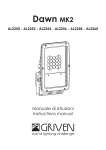
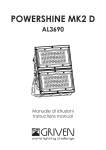
microDIVE MK2
AL2680 - AL2682 - AL2684
Manuale di istruzioni
Instructions manual
INDICE
1.0 Introduzione...................................................................................................................................4
1.1 Informazioni di sicurezza.........................................................................................................................................4
1.1.1 Protezione da scariche elettriche ..................................................................................................................4
1.1.2 Installazione .....................................................................................................................................................4
1.1.3 Protezione dagli incendi .................................................................................................................................4
1.1.4 Protezione da solidi e liquidi...........................................................................................................................4
1.2 Condizioni di garanzia ............................................................................................................................................4
1.3 Normative .................................................................................................................................................................4
2.0 Dimensioni .....................................................................................................................................5
3.0 Imballo e trasporto .......................................................................................................................5
3.1 Imballo......................................................................................................................................................................5
3.2 Trasporto ...................................................................................................................................................................5
4.0 Installazione ..................................................................................................................................6
4.1 Fissaggio ...................................................................................................................................................................6
4.1.1 Installazione fissa .............................................................................................................................................4
4.1.2 Installazione su una struttura mobile .............................................................................................................4
4.2 Orientamento del fascio di luce ............................................................................................................................6
4.3 Alimentazione del proiettore..................................................................................................................................7
4.4 Connessione del proiettore al Transformer Box AL1861.......................................................................................7
5.0 Manutenzione ...............................................................................................................................8
5.1 Pulizia del proiettore ................................................................................................................................................8
5.2 Controlli periodici ....................................................................................................................................................8
6.0 Parti di ricambio............................................................................................................................8
7.0 Smaltimento dell ‘apparecchiatura............................................................................................8
8.0 Specifiche tecniche .....................................................................................................................9
INDEX
1.0 Introduction .................................................................................................................................10
1.1 Safety information..................................................................................................................................................10
1.1.1 Protecting against electric shock ................................................................................................................10
1.1.2 Installation ......................................................................................................................................................10
1.1.3 Protection against burns and fire .................................................................................................................10
1.1.4 Weather protection........................................................................................................................................10
1.2 Warranty conditions...............................................................................................................................................10
1.3 Compliance ...........................................................................................................................................................10
2.0 Size ...............................................................................................................................................11
3.0 Packaging and transpor ............................................................................................................11
3.1 Packaging ..............................................................................................................................................................11
3.2 Transport .................................................................................................................................................................11
4.0 Installation ...................................................................................................................................12
4.1 Fixing .......................................................................................................................................................................12
4.1.1 Fixed installation ............................................................................................................................................10
4.1.2 Installation onto a mobile structure (truss) ..................................................................................................10
4.2 Adjust light beam direction ..................................................................................................................................12
4.3 Powering up the unit..............................................................................................................................................13
4.4 Connection from microCLIP MK2 and Transformer box AL1861 .......................................................................13
5.0 Maintenance...............................................................................................................................14
5.1 Cleaning the unit ...................................................................................................................................................14
5.2 Regular checks ......................................................................................................................................................14
6.0 Spare parts ..................................................................................................................................14
7.0 Disposal........................................................................................................................................14
8.0 Technical specifications ............................................................................................................15
1.0 Introduzione
1.1 Informazioni di sicurezza
Attenzione!
Questo prodotto è adatto solo ad un uso professionale, non ad un uso domestico.
1.1.1 Protezione da scariche elettriche
• Togliere l’alimentazione prima di effettuare qualsiasi operazione all’interno dell’apparecchiatura.
• Prima di connettere l’apparecchio all’alimentatore, verificate la compatibilità di tensione e corrente.
• Non maneggiate il prodotto con mani bagnate o in presenza di acqua.
• Controllate periodicamente che il cavo di alimentazione non sia schiacciato o danneggiato.
• Rivolgersi ad un tecnico qualificato per qualsiasi operazione di manutenzione ordinaria non descritta nel
presente manuale.
•
III
Apparecchio di classe terza. Utilizza tensioni inferiori ai 50 Volts. Esclude e vieta la messa a terra.
1.1.2 Installazione
• Fissate il proiettore con viti, ganci o altri supporti in grado di sostenerne il peso.
• Se fissate l’apparecchiatura ad una struttura sospesa sopra il livello del terreno, verificare che la struttura possa
sostenere almeno dieci volte il peso di tutti i dispositivi installati.
• Le operazioni di installazione dell’apparecchiatura devono essere eseguite da personale competente e
qualificato.
1.1.3 Protezione dagli incendi
•
Idoneo ad essere installato su superfici normalmente infiammabili.
• Non installate l’apparecchio in locali in cui la temperatura ambiente supera i 40° (104°F).
1.1.4 Protezione da solidi e liquidi
Il proiettore rientra nella classificazione di apparecchio con grado di protezione IP68.
•
Sostituite gli schermi di protezione danneggiati utilizzando ricambi GRIVEN.
1.2 Condizioni di garanzia
• Ogni articolo prodotto dalla ditta italiana GRIVEN Srl è stato assemblato e costruito in conformità alle vigenti
norme e normative CE.
• Ogni singolo prodotto e componente sono stati testati prima dell’assemblaggio finale ed ogni prodotto è sottoposto ad un controllo di qualità interno prima di essere spedito.
• GRIVEN Srl garantisce la buona qualità e realizzazione dei propri prodotti e si impegna a riparare o sostituire a
propria discrezione, nel più breve tempo possibile, qualsiasi parte che – durante il periodo di garanzia – mostri
difetti di costruzione, assemblaggio o materiale.
• La garanzia è valida per la durata di 12 (dodici) mesi dalla data di consegna del prodotto.
• GRIVEN Srl non risponde dei danni riportati dal prodotto durante il trasporto oppure derivanti da un utilizzo improprio o da un’inappropriata manutenzione dello stesso.
• Sono escluse dalla presente garanzia tutte le parti considerate di consumo o soggette a normale logorio.
• Il cliente dovrà restituire le parti difettose alla GRIVEN Srl a suo carico e rischio.
• Le parti riparate o sostituire verranno spedite dalla GRIVEN ex-factory.
• Per ogni controversia sarà competente il foro di Mantova (Italia) in conformità alla relativa giurisdizione italiana.
1.3 Normative
• L’apparecchio soddisfa i requisiti della normativa EN60598-1.
• L’apparecchio soddisfa i requisiti della direttiva 2002/95/CE (RoHS).
4
Italiano
80mm
3.1”
147.5mm
5.8”
Ø135mm
5.3”
2.0 Dimensioni
77,2mm
3.0”
161.5mm
6.4”
3.0 Imballo e trasporto
3.1 Imballo
Controllate attentamente il contenuto del cartone e, in caso di danni al prodotto, contattate il Vs. trasportatore.
Nell’imballaggio del presente proiettore sono contenuti i seguenti prodotti:
n° 1 proiettore microDIVE MK2
n° 1 manuale di istruzioni
Attenzione!
• La responsabilità di Griven S.r.l. cessa all’atto della consegna del materiale al vettore: reclami per eventuali
danni dovuti al trasporto dovranno essere indirizzati direttamente al corriere.
• Si accettano reclami entro e non oltre i 7 giorni dal ricevimento della merce.
• Eventuali resi di materiale dovranno essere autorizzati da Griven S.r.l. ed inviati completi della documentazione
fiscale necessaria.
3.2 Trasporto
Si raccomanda di trasportare l’apparecchiatura con estrema attenzione, utilizzando il suo imballo originale per
evitare di danneggiare il prodotto.
Italiano
5
4.0 Installazione
4.1 Fissaggio
6,
0. 2mm
2”
Ø
8.
0. 5mm
3”
Ø
Ø
6,
0. 2mm
2”
Il proiettore può essere utilizzato sia appoggiato a terra che fissato ad una struttura e può funzionare in qualsiasi
posizione.
4.1.1 Installazione fissa
Utilizzare i fori Ø6.2 e Ø8.5 sulla forcella
l’apparecchiatura.
per fissare
45mm
1.8”
90mm
3.5”
A
4.1.2 Installazione ad una struttura mobile (americana)
Per agganciare il proiettore ad una struttura di supporto o americana, consigliamo l’utilizzo di ganci “A” tipo “Aliscaff” fissati al
proiettore mediante i fori sulla forcella, come indicato nella figura seguente.
Attenzione!
Verificate che il gancio di montaggio (non incluso) non sia danneggiato
e che possa sostenere almeno 10 volte il peso dell’apparecchiatura.
Verificate che la struttura possa sostenere almeno 10 volte il peso dell’apparecchiatura,
dei ganci, degli equipaggiamenti ausiliari, etc.
4.2 Orientamento del fascio di luce
B
1. Allentate le viti laterali “B”.
6
2. Ruotare il corpo nella direzione desiderata
e serrate le viti.
Italiano
4.3 Alimentazione del proiettore
Il proiettore funziona con alimentatori per led a 350mA.
Per evitare danni permanenti al
proiettore, rispettare scrupolosamente
lo schema di collegamento!!
BIANCO
ROSA
MARRONE
GIALLO
VERDE
GRIGIO
BLU
N.C.
ROSSOROSSO+
VERDEVERDE+
BLUBLU+
4.4 Connessione del proiettore al Transformer Box AL1861
Attenzione!
• Prima di collegare l’apparecchio assicuratevi che la fornitura elettrica corrisponda a quelle ammesse.
• Le operazioni di cablaggio e collegamento devono essere eseguite da personale qualificato.
microDIVE MK2
Transformer box
AL1861
massimo 50 metri - sezione minima 0.35 mm²
E’ possibile collegare da 1 a 4 proiettori.
Italiano
7
5.0 Manutenzione
Per assicurare la massima funzionalità e resa ottica si raccomanda di attenersi alle istruzioni riportate qui di seguito.
Attenzione!
Togliete tensione prima di effettuare qualsiasi operazione sul proiettore.
5.1 Pulizia del proiettore
Il proiettore deve essere pulito regolarmente. La frequenza della pulizia dipende soprattutto dall’ambiente nel
quale l’apparecchiatura funziona, infatti polvere eccessiva, depositi di fumo ed altre scorie riducono le prestazioni ottiche.
• Pulite regolarmente il vetro del proiettore
• Non usare solventi che potrebbero danneggiare le superfici verniciate.
5.2 Controlli periodici
• Controllate i collegamenti elettrici ed in particolare la messa a terra ed il cavo di alimentazione.
• Controllate che il proiettore non sia danneggiato meccanicamente ed eventualmente sostituite le parti deteriorate.
6.0 Parti di ricambio
Tutti i componenti del proiettore sono disponibili come parti di ricambio presso i rivenditori Griven.
Le viste esplose, lo schema elettrico e il diagramma elettronico sono disponibili su richiesta.
Per facilitare il lavoro del centro di assistenza ricordate di specificare il numero di serie ed il modello del proiettore di cui avete richiesto i ricambi.
7.0 Smaltimento dell ‘apparecchiatura
La direttiva Europea 2002/96/CE sui rifiuti di apparecchiature elettroniche (RAEE), prevede che gli apparecchi
illuminanti non debbano essere smaltiti nel normale flusso dei rifiuti solidi urbani. Gli apparecchi dismessi debbono
essere raccolti separatamente per ottimizzare il tasso di recupero e riciclaggio dei materiali che li compongono
ed impedire potenziali danni per la salute e l’ambiente.
Il simbolo del cestino barrato è riportato su tutti i prodotti per ricordare gli obblighi di raccolta
separata.
Per ulteriori informazioni sulla corretta dismissione delle apparecchiature, i detentori potranno rivolgersi al servizio
pubblico preposto o ai rivenditori.
8
Italiano
8.0 Specifiche tecniche
Caratteristiche meccaniche
Altezza . . . . . . . . . . . . . . . . . . . . . . . . . . . . . . . . . . . . . . . . . . . . . . . . . . . . . . . . . . . . . . . . . . . . . . . . . . . . . . .147mm (5.8”)
Ø . . . . . . . . . . . . . . . . . . . . . . . . . . . . . . . . . . . . . . . . . . . . . . . . . . . . . . . . . . . . . . . . . . . . . . . . . . . . . . . . . .Ø135mm (5.3”)
Peso . . . . . . . . . . . . . . . . . . . . . . . . . . . . . . . . . . . . . . . . . . . . . . . . . . . . . . . . . . . . . . . . . . . . . . . . . . . . . . . . .1.6Kg (3.5Lbs)
Caratteristiche termiche
Massima temperatura ambiente . . . . . . . . . . . . . . . . . . . . . . . . . . . . . . . . . . . . . . . . . . . . . . . . . . . . . . . . . .40°C (104°F)
Massima temperatura superficiale . . . . . . . . . . . . . . . . . . . . . . . . . . . . . . . . . . . . . . . . . . . . . . . . . . . . . <60°C ( <140°F)
Caratteristiche elettriche
Tensione di alimentazione . . . . . . . . . . . . . . . . . . . . . . . . . . . . . . . . . . . . . . . . . . . . . . . . . . . . . . . . . . . . . . . . . . . .12 Vdc
Corrente nominale . . . . . . . . . . . . . . . . . . . . . . . . . . . . . . . . . . . . . . . . . . . . . . . . . . . . . . . . . . . . . . . . . . . . . 350mA max
Potenza massima . . . . . . . . . . . . . . . . . . . . . . . . . . . . . . . . . . . . . . . . . . . . . . . . . . . . . . . . . . . . . . . . . . . . . . . . . . . . 10.8W
Sorgente luminosa
Tipo sorgente luminosa . . . . . . . . . . . . . . . . . . . . . . . . . . . . . . . . . . . . . . . . . . . . . . . . . . . . . . . . . . . . . 3 Led RGB x 3.6W
Ottica
Sistema ottico . . . . . . . . . . . . . . . . . . . . . . . . . . . . . . . . . . . . . . . . . . . . . . . . . . . . . . . . . . . . . . . . . . . . . . . . . . . . . . A lenti
Ottiche disponibili . . . . . . . . . . . . . . . . . . . . . . . . . . . . . . . . . . . . 12° cod. AL2680 / 28° cod. AL2682/ 40° cod. AL2684
Costruzione
Corpo proiettore . . . . . . . . . . . . . . . . . . . . . . . . . . . . . . . . . . . . . . . . . . . . . . . . . . . . . . . . . . . . . . . . . . . . . . . Acciaio inox
Fattore di protezione . . . . . . . . . . . . . . . . . . . . . . . . . . . . . . . . . . . . . . . . . . . . . . . . . . . . . . . . . . . . . . . . . . . . . . . . . . . IP68
Italiano
9
1.0 Introduction
1.1 Safety information
Warning!
This unit is suitable for professional use only, not for domestic use.
1.1.1 Protecting against electric shock
• Disconnect the unit from mains supply before servicing it or performing any other action.
• Before connecting the unit to power supplies, verify that operating voltage and current are compatible.
• Do not handle the unit with wet hands or in the presence of water.
• Check regularly that the power supply cable is not damaged or crushed.
• Apply to a qualified technician for any regular maintenance action not described in this manual.
•
III
Class 3 device. It uses operatin voltages inferior to 50 Volts. It excludes and forbit ground connection.
1.1.2 Installation
• The unit installation actions must be performed by a qualified staff.
• Fix the unit with screws, hooks or any other support able to bear the weight of the unit itself.
• If the unit is fixed onto a suspended structure, this structure is supposed to bear at least ten times the weight of
all devices to be fixed.
1.1.3 Protection against burns and fire
•
Suitable to be installed onto normally inflammable surfaces.
• The unit is not to be installed in places where the ambient temperature exceeds 40° (104°F).
1.1.4 Weather protection
The unit is classified as device with an IP65 weather protection rate.
•
Replace any damaged shields with original GRIVEN spare parts..
1.2 Warranty conditions
• Each product manufactured by GRIVEN srl of Italy is assembled and built in accordance to current CE conformity rules and regulations.
• Every single product and component has been tested before the final assembling and all products must pass
the in-house quality control before they are shipped.
• GRIVEN srl of Italy guarantees the good quality and manufacture of the products and undertakes to repair or
supply again, according to his opinion and free of charge, within the shortest time possible, any part that shows
- during the guarantee period - defects of constructions, manufacture or material.
• The guarantee is valid for 12 (twelve) months starting from the delivery date of the products.
• GRIVEN srl of Italy does not respond for damages occurred to the units during transport and for irrational use and
inaccuracy in regular maintenance of the products.
• The guarantee excludes all consumables.
• The customer will take care of the return of the faulty parts to GRIVEN srl of Italy, at his own charge and risk.
• The parts which have been repaired or replaced are sent by GRIVEN srl of Italy ex-factory.
• For any dispute, the Court of Mantova (Italy) will be competent and in conformity with relevant jurisdiction the
Italian Law is enforced for any controversy.
1.3 Compliance
• Product in compliance with EN60598-1.
• Product in compliance with 2002/95/CE (RoHS).
10
English
80mm
3.1”
147.5mm
5.8”
Ø135mm
5.3”
2.0 Size
77,2mm
3.0”
161.5mm
6.4”
3.0 Packaging and transport
3.1 Packaging
Check carefully the content of the box and, in case of damage, contact your forwarder immediately.
The following items are included in the box of this unit:
n° 1 microDIVE MK2 unit
n° 1 owner’s manual
Warning!
• Griven S.r.l. liability will cease upon consignment of goods to the forwarder: claims for damage due to transport must be addressed directly to the forwarder.
• Griven S.r.l. will accept claims for broken or missing goods only within seven days of receipt of the goods.
• Returns of equipment will not be accepted without prior authorization granted by Griven S.r.l. and if not duly accompanied by relevant shipping documents.
3.2 Transport
It is recommended to transport the unit with the maximum care, by using its original packing, to avoid to
damage the unit.
English
11
4.0 Installation
4.1 Fixing
6,
0. 2mm
2”
Ø
8.
0. 5mm
3”
Ø
Ø
6,
0. 2mm
2”
The unit can be used both rested on floor and fixed onto a structure. The unit can operate in any position.
4.1.1 Fixed Installation
Use the holes Ø6.2 and Ø8.5 in the bracket to fix the unit.
45mm
1.8”
90mm
3.5”
A
4.1.2 Installation onto a mobile structure (truss)
To fix the unit onto a supporting structure or truss, it is suggested
to use hooks “A” type “Aliscaff”. The hooks are to be fitted to the
unit through the holes in the bracket, as shown in the picture.
Warning!
Check that the fixing hook is not damaged and is able to bear at least 10 times the weight of the unit.
Check that the structure can bear at least 10 times the weight of the unit,
the hooks, the additional equipments, etc.
4.2 Adjusting light beam direction
B
1. Untighten the lateral screw “B”, rotate the
body of the unit towards desired direction
and tighten the knobs.
12
2. Rotate the body of the unit towards desired
direction and tighten the screw “B”.
English
4.3 Powering up the unit
The unit can operate with standard 350mA led driver.
In order to avoid permanent
damage to the unit, the connection
scheme must be strictly respected!!
WHITE
PINK
BROWN
YELLOW
GREEN
GRAY
BLUE
N.C.
REDRED+
GREENGREEN+
BLUEBLUE+
4.4 Connection from microCLIP MK2 and Transformer box AL1861
Warning!
• Before connecting the unit, verify that power supplies features are compatible with the unit features.
• Wiring and connection actions are to be performed by a qualified staff.
microDIVE MK2
Transformer box
AL1861
maximum 50 meters
minimum section 0.35 mm²
Minimum 1 unit - Maximum 4 unit
English
13
5.0 Maintenance
Attention!
Always remove mains power prior to opening up the fixture.
To ensure maximum functionality and light output it is recommended to follow these instructions:
5.1 Cleaning the unit
The unit must be cleaned regularly. Cleaning regularity will depend especially on the environment where the unit
will operate: deposits of dust, smokes or other wastes will reduce the light output performances.
• Clean regularly the glass of the unit.
• Do not use solvents which could damage painted surfaces.
5.2 Regular checks
• Check electrical connections, especially the ground wiring and the power supply cable.
• Check that the unit is not damaged mechanically. Replace those components which have got deteriorated.
6.0 Spare parts
All components of the unit are available as spare parts at Griven dealers.
Exploded views, wiring diagrams, electronic layouts and advertising brochures are available on request.
To make the job of assistance centres easier, specify serial number and model of the unit which spare parts are
requested for.
7.0 Disposal
The European Directive 2002/96/EC on Waste Electrical and Electronic Equipment (WEEE), requires that old
lighting fixtures must not be disposed of the normal unsorted municipal waste stream. Old appliances must be
collected separately in order to optimise the recovery and recycling of the materials they contain and reduce
the impact on human health and the environment.
The crossed out “wheeled bin” symbol on the product reminds you of your obligation, that when you
dispose of the appliance it the must be separately collected.
Consumer should contact their local authority or retailer for information concerning the correct disposal of their
old appliance.
14
English
8.0 Technical specifications
Mechanical features
Height . . . . . . . . . . . . . . . . . . . . . . . . . . . . . . . . . . . . . . . . . . . . . . . . . . . . . . . . . . . . . . . . . . . . . . . . . . . . . . . 147mm (5.8”)
Ø Lower . . . . . . . . . . . . . . . . . . . . . . . . . . . . . . . . . . . . . . . . . . . . . . . . . . . . . . . . . . . . . . . . . . . . . . . . . . . . Ø135mm (5.3”)
Weight . . . . . . . . . . . . . . . . . . . . . . . . . . . . . . . . . . . . . . . . . . . . . . . . . . . . . . . . . . . . . . . . . . . . . . . . . . . . . . 1.6Kg (3.5Lbs)
Thermal features
Maximum ambient temperature . . . . . . . . . . . . . . . . . . . . . . . . . . . . . . . . . . . . . . . . . . . . . . . . . . . . . . . . . .40°C (104°F)
Maximum surface temperature . . . . . . . . . . . . . . . . . . . . . . . . . . . . . . . . . . . . . . . . . . . . . . . . . . . . . . . . <60°C ( <140°F)
Electrical features
Voltage . . . . . . . . . . . . . . . . . . . . . . . . . . . . . . . . . . . . . . . . . . . . . . . . . . . . . . . . . . . . . . . . . . . . . . . . . . . . . . . . . . . .12 Vdc
Nominal current . . . . . . . . . . . . . . . . . . . . . . . . . . . . . . . . . . . . . . . . . . . . . . . . . . . . . . . . . . . . . . . . . . . . . . . . . . . . 350mA
Maximum power . . . . . . . . . . . . . . . . . . . . . . . . . . . . . . . . . . . . . . . . . . . . . . . . . . . . . . . . . . . . . . . . . . . . . . . . . . . . 10.8W
Light output source
Type of light output source . . . . . . . . . . . . . . . . . . . . . . . . . . . . . . . . . . . . . . . . . . . . . . . . . . . . . . . . . 3 Leds RGB x 3.6W
Optics
Optical system . . . . . . . . . . . . . . . . . . . . . . . . . . . . . . . . . . . . . . . . . . . . . . . . . . . . . . . . . . . . . . . . . . . . . . . . . . . . . Lenses
Available optics . . . . . . . . . . . . . . . . . . . . . . . . . . . . . . . . . . . . . . 12° cod.AL2680 / 28° cod.AL2682 / 34° cod.AL2684
Construction
Unit body . . . . . . . . . . . . . . . . . . . . . . . . . . . . . . . . . . . . . . . . . . . . . . . . . . . . . . . . . . . . . . . . . . . . . . . . . . . . Stainless steel
Weather protection rate . . . . . . . . . . . . . . . . . . . . . . . . . . . . . . . . . . . . . . . . . . . . . . . . . . . . . . . . . . . . . . . . . . . . . . . IP68
English
15
Via Bulgaria, 16 - 46042 CASTEL GOFFREDO (MN) - Italy
Telefono 0376/779483 - Fax 0376/779682 - 0376/779552
http://www.griven.com/ e-mail [email protected]
http://www.griven.it/ e-mail [email protected]
User’s manual rel. 2.20