1
2001
BICYCLE SHOCKS
SERVICE MANUAL
www.foxracingshox.com
Copyright © 2001 by Fox Factory Inc.
1
2
TABLE OF CONTENTS
Policies and Shared Procedures
1.
2.
3.
4.
Policies and Warranty Procedures - Page 4
Reducers and Bushings - Page 14
Nitrogen Pellets - Page 18
Float Air Sleeve Service - Page 24
Vanilla
5.
6.
7.
Vanilla, Vanilla R and Vanilla RC Drawings and Parts Lists - Page 30
Vanilla and Vanilla R Service Instructions - Page 46
Vanilla RX and Vanilla RC Service Instructions - Page 62
FLOAT
8. FLOAT Drawings and Parts Lists - Page76
9. FLOAT and FLOAT R Service Instructions - Page94
10. FLOAT RC Service Instructions - Page 110
Appendices
11.
12.
13.
14.
15.
16.
Tool List - Page 122
Torque Specification Table - Page 126
Tuning Table - Page 130
IFP Setting Table - Page138
Seal kits - Page 138
Warranty Records – Master Sheets for Copier - Page 146
3
Policies and Warranty Procedures
4
5
6
2001
POLICIES AND PROCEDURES
FOX RACING SHOX
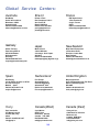
GLOBAL SERVICE CENTER
FOX Racing Shox is proud of our racing heritage and of the sustained quality of our products. With professional help of
International Service Centers like yours we will maintain this Standard of quality and high performance worldwide.
The following describes FOX Policies relating to service and warranty.
The Policies and Procedures document contains information on:
1.
2.
3.
4.
5.
6.
7.
Starting your Fox Service Center
General Service/Warranty Policies
Warranty Procedures
Service
Re-Valving Policy
The Fox Service System
Certification
SECTION 1: STARTING YOUR FOX SERVICE CENTER
Welcome to FOX Racing Shox, we are excited to start working with you. All FOX service centers are required to
have a broad and complete assortment of parts allowing them to provide prompt and quality service to FOX
customers. To get you up and running quickly, FOX has compiled “Start Up Kit”. All new Service Centers are
required to purchase the “Start Up Kit”. The “Start Up Kit” includes most common daily warranty parts and tools
needed.
Kit includes:
·
Detailed selection of parts
·
FOX Parts Catalog / USA Suggested Retail Price List
·
Special FOX Tools
·
FOX Specific Forms
·
FOX Set Up Manuals
·
FOX Rebuild Manual
·
FOX Window Decals
·
Service Center Training
Our comprehensive FOX parts catalog lists more than 300 additional parts not found in the “Start Up Kit”. All the
parts listed in our Bicycle Catalog may be ordered individually to effectively handle most FOX Shox repairs.
SECTION 2: GENERAL SERVICE/WARRANTY POLICIES
A)
Authorized Service Centers are required to maintain a high standard of excellence when working with FOX
customers and the repair and service of their FOX shocks.
B)
FOX Authorized Service Centers should be easy to contact. A recorded message clearly stating the service
center’s FOX affiliation and other informative information should be available to the FOX customer when a
service center representative is not. The use of e-mail is highly recommended. E-mail is particularly useful
when working with a person in another time zone (i.e., when communicating with FOX).
C)
Authorized Service Centers are expected to complete the repair/service of all FOX shocks in a timely manner.
In the event that a timely repair/service cannot be achieved (i.e., part availability) the Service Center is required
to inform the FOX customer of the delay and its estimated completion date. Any changes in the completion
date should be immediately communicated to the FOX customer.
7
D)
All Authorized Service Centers are required to use only Original FOX Racing Shox Parts in the repair/service of
all FOX shocks. Any substitute parts must be of equal quality and APPROVED BY FOX RACING SHOX BEFORE
BEING USED.
E)
Only Authorized FOX Service Centers are able to obtain many of FOX Racing Shox proprietary parts. These
items are of a technical nature to be used by a trained technician in the repair or service of FOX shocks. Only
items appearing on the FOX Retail Price List may be resold by the Authorized Service Center outside the repair
or service of a FOX shock without first obtaining written permission from FOX.
GENERAL SERVICE / WARRANTY POLICY cont.
F)
Authorized FOX Service Centers will receive a 35% discount off the FOX suggested retail price.
G)
FOX requires all Authorized Service Centers to warranty all service performed on FOX shocks for a period of 3
months. All cost incurred by the Service Center in the event of a 3-month warranty repair rework, is the
responsibility of the Service Center with the exception of abuse, neglect, design defects, tampering, or lack of
service.
SECTION 3: WARRANTY PROCEDURES
A)
WARRANTY
THE WARRANTY PERIOD FOR A FOX SHOCK IS ONE YEAR FROM DATE OF PURCHASE OF BICYCLE/SHOCK.
This warranty is void when damage to the shock has occurred from the following:
·
Abuse
·
Damage to the exterior finish
·
Disassembly or any attempt to disassemble
·
Modifications
·
Non-factory oil changes
·
Shipping damages/loss (purchase of full value insurance is recommended).
·
Absence of Proof of Purchase
Each Service Center is required to validate the age of the shock being considered for warranty. It is the
responsibility of the Service Center to keep any and all documents or notes obtained during the validation
process for a period of one year after the completion of the warranty service. All service centers will be
randomly audited for accuracy in this area. FOX will perform random audits of original warranty validation
paperwork at their discretion.
B)
Warranty Requirements for Bike Shops and Customers on used shocks:
Bicycle shops and retail customers must provide the Service Center with a valid copy of sales receipt showing the
original purchase at less than one year and meet the FOX warranty policy requirements to be eligible for warranty.
Any shocks that do not meet these requirement but are still being considered for warranty because of extenuating
circumstances, must be approved by FOX before the work is performed to insure warranty reimbursement.
C)
Warranty Requirements for Bike Shops on new shocks:
Sometimes shocks are deemed faulty before the bike is ever sold so there is no original purchase documentation.
In this situation the following information is to be obtained:
Bike Manufacture
Year & Model
Serial Number
When a bike shop submits a shock warranty consideration by this method, the shock must be of new condition.
No warranty work should be performed on any shocks received with obvious signs of use until a copy of the
original proof of purchase is obtained by the Service Center.
8
D)
Warranty Requirements for OEM’s and their distributors:
Ideally all shocks being submitted for warranty, by an OEM/Distributor to a Service Center, will be accompanied by
proper documentation (a valid copy of the original proof of purchase showing the shock to be less than a year old)
and meet the FOX warranty policy requirements. It is sometimes difficult for OEM’s and/or their distributors to
supply receipts because of the many hands a receipt would have to go through to accompany the shock to the
Service Center. FOX will accept shocks from OEM’s and/or their distributors without receipts when necessary.
It is critical to perform OEM service as soon as possible as to allow the OEM time to return the shock to their
customer in a timely manner. Please do not allow questions or problems with OEM shocks to linger.
When a shock/s must be submitted without proper documentation, the Service Center will visually inspect the
shock/s on arrival for warranty consideration. The Service Center is then authorized by FOX to determine whether
the shock should be warranty or not. The Service Center would then inform the OEM/Distributor of its findings.
Service centers are encouraged to contact FOX with any questionable situations.
All service centers are required to record sufficient explanations for all OEM/Distributor shocks repaired under
warranty without proper documentation on the FOX warranty form. Excessive claims of this type will be audited.
This method of “visual warranty” may only be used for OEM’s or their distributors, NOT BIKE SHOPS or INDIVIDUALS.
E)
Shipping
FOX will reimburse Authorized Service Centers for return ground/standard shipping to their customers on warranty
shocks. FOX will reimburse for standard ground shipping (up to maximum amount US$8.00 per shock warranty
claim). Any expedited return shipping is the responsibility of the customer.
Shipping to the service center, in the case of a service or warranty shock, is the responsibility of the customer.
Warranty Forms
The necessary warranty reimbursement forms are supplied with the “Start-Up Kit”. Service Centers may make
copies, or order additional forms from FOX, when necessary. There are 2 forms required to make a warranty
claim, the “Warranty Record Form” (one per warranty shock serviced) and the “Warranty Summary Form”.
Warranty Record Form:
A “Warranty Record Form” must be completed for each shock serviced. A compilation of the information on these
forms is used to complete the “Warranty Summary Form” .
Warranty Summary Form:
The “Warranty Summary Form” is to be completed by the Service Center and submitted with the corresponding
“Warranty Record Forms” to FOX Racing Shox for processing of the warranty claim . Warranty claims may be
submitted on a monthly, bimonthly or quarterly basis.
F)
Warranty Parts Replacement
FOX will ship all parts used by an individual Service Center, in the warranty repair of FOX shocks, with the same or
equivalent part, at a 100% discount. Limited to parts on hand and/or not discontinued. Shipping of the warranty
replacement parts to the Service Center will be paid by FOX ( not including any import taxes, tariffs, customs , or
broker fees). Shipping charges on warranty parts orders and service parts orders, when shipped together, will be
shared by FOX and the Service Center based on the weights of the individual orders. At FOX’s discretion, the
Service Center may be permitted to add a small service parts order to the warranty parts order and maintain the
“free shipping” status.
All Service Centers are required to keep ALL parts used in the warranty repair of a FOX shock in an organized and
cataloged manner for a period of one year. All service enters will be required to produce said parts upon demand
by FOX Racing Shox for this one year period.
9
G)
Warranty Labor Reimbursement
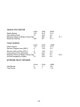
FOX will pay a warranty reimbursement fee for warranty services rendered.
Note: The amounts listed represent reimbursement for shop time, administrative cost, handling and packaging
material fees.
Warranty Codes and corresponding Reimbursement Values: US DOLLARS
SERV201
SERV206
SERV211
SERV216
ALPS 4
ALPS 4R
ALPS 5
ALPS 5R
Out of warranty period
Out of warranty period
Out of warranty period
Out of warranty period
SERV221
SERV226
SERV231
SERV236
SERV241
Vanilla
Vanilla R
Vanilla RX
Vanilla X
Vanilla RC
$21.50
$26.50
$26.50
Out of warranty period
$26.50
SERV246
SERV251
SERV256
Air Vanilla RC
Air Vanilla
Air Vanilla R
Out of warranty period
Out of warranty period
Out of warranty period
SERV261
SERV266
SERV271
Air Vanilla Float
Air vanilla Float R
Air Vanilla Float RC
Out of warranty period
Out of warranty period
Out of warranty period
SERV276
SERV281
SERV286
FLOAT 2000
FLOAT R 2000
FLOAT RC 2000
$26.50
$26.50
$26.50
SERV290
SERV291
SERV292
SERV295
Air Vanilla Air Sleeve Rebuild
Air Vanilla FLOAT Air Sleeve Rebuild
FLOAT 2000 Air Sleeve Rebuild
Stuck Air Vanilla FLOAT Rework
$12.50
$12.50
$12.50
$18.00
H) Warranty Auditing
All Authorized FOX Service Centers will be subject to random audits. For this reason it will not be necessary to
send original purchase receipts or old parts back to FOX with your warranty claims. Service Centers must be
prepared to provide FOX Racing Shox with the required paper work used to validate previous warranty claims,
and all warranty replacement parts used in the repair of warranty shocks, in an organized manner upon
demand for up to a 12 month period from the time the warranty work was completed..
SECTION 4: FOX SERVICE
After the one-year warranty period we move into the service life cycle of the FOX shock.
·
This would entail all service necessary for maintenance and repair of Fox Bicycle Shox.
·
Regular service charges in the United States range from $25.00 dollars to $40.00 dollars. This service
charge covers the labor to disassemble, replace seals and oil, and reassemble.
·
There is additional charges for parts used. Suggested US retail prices are supplied in parts catalog.
·
Additional service parts can be purchased from the FOX parts catalog for general service.
·
FOX Racing Shox will provide Service Centers with an approved resale parts list that can be sold to
general public and bicycle dealers.
·
Non- resale parts and tooling are not for resale to general public, Bicycle dealers or non-authorized
service centers. Any sales of this type will void your FOX Authorized Service Center status immediately.
10
SECTION 5: REVALVE POLICY
Most common revalving situations:
· Float (with no rebound adjuster)
· Vanilla (with no rebound adjuster)
Revalving of shox can be done under warranty within 90 days of purchase, again with dated copy of original
purchase.
FOX charges $8.00 in addition to standard service labor costs for non-warranty revalving . Parts are extra.
SECTION 6: THE FOX SERVICE SYSTEM
Many of you have your own internal service system for keeping track of service work, which will work fine.
The following is a basic description of the FOX system.
·
Customer calls in for service and it is determined the shock must come in for repair.
·
Our customer representative issues a Return Authorization number and asks the customer to write this
# on the outside of the package along with a note inside describing the shocks failure.
·
The shock is entered in the computer as received.
·
The RA# written on a paper toe tag which is attached to the top of the shock. This allows identification
at any stage of repair.
·
The shock now goes to the shop for diagnosis and repair.
·
Once the shock is repaired the service technician writes down every part used and services rendered
using FOX service codes and part numbers.
·
This information is then entered in to the order and the proper charges are calculated and charged
either to credit cared or COD etc. The shock then goes to shipping.
·
Shipping double checks the toe tag to the paper work to make sure everything matches and then the
shock ships.
SECTION 7: CERTIFICATION
A)
All FOX products are precise, high quality pieces of equipment and must be handled as such. We know that
you are highly qualified to service our equipment however FOX engineers have specified proprietary techniques in assembly and tooling that will be necessary for you to know and follow to achieve the top performance that FOX is known for.
B)
Your technicians need to be trained and certified by our FOX technicians. Certification courses take place at
FOX Racing Shox facility in the United States and will cover all serviceable FOX shox bicycle products.
C)
Your Service Center will also be listed on our Web site FOX as an official Service Center.
Fill out the “Warranty Reimbursement Form” as described below:
·
Date: The date the warranty started.
·
RA#: Assign the shock an Return Authorization Number (RA). It is important to assign a number to the
shock for use in the “Warranty Summary”.
11
·
Customer Name: Name of the customer or shop returning the shock for repair.
·
Phone Number: Customer’s phone number.
·
Contact: Name of person calling.
·
Shock Model: The model of shock to be worked on.
·
Make and Model of Bike: The brand of bike and which model.
·
Original Purchase Date: Get this information from the customer’s copy of sales receipt. This is very
important, no warranties will be processed without this information.
·
Receipt on File: Fill this box in with a yes or no.
·
Country of Origin: The country the shock was sent from for repair.
·
Service Code: Write the FOX service code here
·
Repair Symptom: List the symptoms the shock has upon first examination.
·
Parts Needed: List all parts necessary for the repair of the shock.
·
Labor Reimbursement: Write the labor reimbursement amount in US dollars associated with this
repair.
·
Shipping Reimbursement: Write the total shipping charge associated with this repair.
At the end of each month, summarize your Warranty Reimbursement Forms onto the “Warranty Labor Summary Form”
and the “Warranty Parts Order Form”.
ALPS 4 bearing assemblies are no longer available, there are still seal kits available however in many cases we
are upgrading to ALPS 5 bearing assemblies at $35.00 dollars (retail).
Note: you should not run into many ALPS 4 warranties due to the length of time these have been in the market.
Fill out the “Warranty Labor Summary Form” & “Warranty Parts Summary Form” as described below:
1.
Date: Date form is started.
2.
Page____ of ____: Number the pages. For example on a two page claim Page 1 is “1 of 2”, Page 2 is “2of2”, etc.
3.
Service Center #: Write your service center number here.
4.
Invoice Number: Please assign an invoice number to your claim. Use any numbering system you like. Each
month’s claim must have a unique number. Use the same invoice number for both the “Warranty labor Summary
Form” and the “Warranty Parts Summary Form”.
5.
Service Center Name: Enter the name of your service center here.
6.
Contact: Who to contact in case of a question on the form.
For the Labor Form:
1.
Enter the corresponding information from each of your Warranty Reimbursement Forms.
For the Parts Form:
2. Enter each part only once. List the total quantity of that part number used for the entire month.
12
13
REDUCERS AND BUSHINGS
14
15
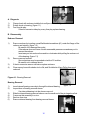
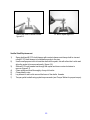
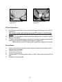
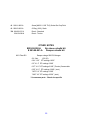
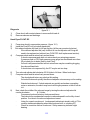
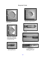
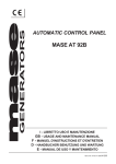
A. Diagnosis
1)
2)
3)
Clamp shock with reducers installed into soft jaw vice.
figure 1.1
Rotate shock on bearing. (figure 1.1)
Feel for side play.
If there is excessive side play or any free play replace bearing.
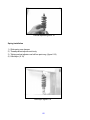
B. Disassembly
Reducer Removal
1)
2)
3)
4)
Remove reducer by inserting a small flat bladed screwdriver (#1) under the flange of the
reducer and twisting. (figure 1.2)
·
Be careful not to damage the eyelet.
·
If the reducer does not come out with reasonable pressure use and easy out to
remove the reducer.
·
Insert easy out into reducer bore and turn clockwise while pulling the reducer out
of the bearing. (figure 1.3)
Remove second reducer.
·
Second reducer may be pounded out with a 0.5 inch bar.
·
Be careful not to damage shock.
If their is excessive wear or corrosion replace reducers.
Clean up any burs with a debur tool or file, and Scotchbrite off any Teflon from good
reducers.
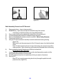
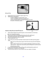
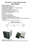
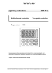
Figure 4-1. Bearing Removal.
Bearing Removal
1)
2)
3)
4)
5)
6)
figure 1.2
Insert internal bearing removal pin through the internal bearing.
Inspect bore of bearing removal sleeve.
·
If an internal bearing is in the sleeve remove it.
Slide the internal bearing removal sleeve over the small end of the pin large bore first.
Compress this assembly in a vice.
Remove from vice.
Remove internal bearing from bearing removal sleeve.
16
figure 1.3
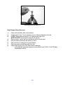
Internal Bearing Assembly
1)
2)
3)
4)
5)
6)
Slide a new internal bearing on the bearing removal pin.
Insert the pin through the hole in the shock eyelet.
Slide the internal bearing removal sleeve over the pin small bore first.
Compress this assembly in a vice.
Remove from vice.
Remove tools.
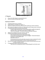
Reducer Assembly
1)
2)
3)
Lubricate bore of internal bearing with grease. ( figure 1.4)
Press reducers into bearing by hand.
Clamp reducers in the vice and rotate.
·
Make sure that the reducers rotate freely in the bearing with no free play.
figure 1.4
17
NITROGEN PELLETS
18
19
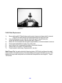
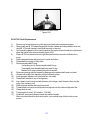
*figure 3.1
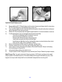
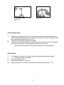
A. Diagnosis
Nitrogen / Air Leak Test
1)
2)
Submerge shock in a container of water. (*figure3.1)
Shake off any initial bubbles.
·
Look for nitrogen bubbles at nitrogen fill pellet or set screw.
* Both fill pellet and air sleeve and valve use same water check method
20
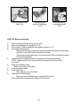
figure 3.2
figure 3.3
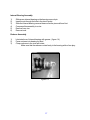
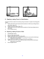
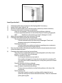
D. Repairing Leaking Thread in Pellet Retainer
Sometimes all that is needed to fix a leaking nitrogen chamber is to tighten the existing pellet
retainer.
1)
Tighten pellet retainer with torque wrench screwdriver to initial torque setting shown in
torque table. (figure 3.2)
2)
Charge shock with nitrogen. (figure 3.3)
3)
Tighten pellet retainer with torque wrench screwdriver to final torque setting shown in
torque table.
4)
Do an nitrogen leak test.
E. Replacing Leaking Thread in Pellet
1)
2)
3)
4)
5)
6)
7)
Unthread pellet retainer.
Remove rubber pellet with pick.
Replace rubber pellet with 90 durometer pellet.
Tighten pellet retainer with torque wrench screwdriver torque wrench to initial torque
setting shown in torque table.
Charge with two hundred psi of nitrogen (FLOAT RC uses 500 psi).
Tighten pellet retainer with torque wrench screwdriver torque wrench to final torque
setting shown in torque table.
Do an nitrogen leak test.
21
figure 3.5
figure 3.4
B. Repairing Press in Pellet
1)
2)
3)
4)
5)
Sometimes all that is needed to fix a leaking nitrogen chamber is to press the existing
pellet retainer in a little. (figure 3.5)
Use a new pellet retainer and place it over the existing plug.
Secure the whole assembly into your vise and tighten, using the new pellet retainer to
push in the existing pellet retainer. (figure 3.4)
Recharge with nitrogen.
Do an nitrogen leak test.
C. Replacing Press in Pellet
1)
2)
3)
4)
5)
6)
7)
Always wear safety glasses.
Point air valve away from you and release air pressure with nitrogen safety needle.
Drill out aluminum plug and rubber filler pellet.
Use appropriate Easy out to turn out bad pellet.
Replace rubber pellet and secure with pellet retainer by pressing pellet retainer into
body with vise.
Recharge with nitrogen.
Do an nitrogen leak test.
22
23
FLOAT AIR SLEEVE SERVICE
24
25
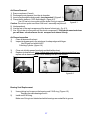
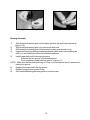
Warning:
FLOAT - Air Sleeve Service
It is possible that high-pressure air may be trapped in the negative side of the air sleeve
chamber. This is known as a ‘STUCK-DOWN’ condition. It is very important that the air sleeve
is removed carefully. The trapped high pressure air may blow the sleeve assembly off of the
body at high speed, possibly causing an injury or death.
Use a shop rag through the body elelet will prevent the air sleeve from blowing off the
body and harming anyone.(figure 4.1)
figure 4.1
26
Air Sleeve Removal
1) Remove reducers (if used).
2) Discharge the air pressure from the air chamber.
3) Insert a rag through the body eyelet. (very important! ) (figure 4.1)
4) Clamp the air sleeve in 1.625 shaft clamps. (figure 4.2).
· Use 1/2 bar to to turn eyelet until the eyelet O-ring is exposed.
figure 4.1
Caution: Do not turn eyelet more than 2 full turns - assembly may blow off.
5) Unclamp shock.
6) Use the rest of the rag to wrap around the sleeve for best grip. (fig. 4.3).
7) Use 1/2 inch bar to turn eyelet until the shock comes apart. If the shock was stuck down
you will hear a loud noise as the air escapes from sleeve & body.
Air Sleeve Inspection
1)
Clean air sleeve with solvent.
2)
Inspect air bypass port in the air sleeve for sharp edges with finger.
·
Use Dremel tool with bit #427:
Polishing Cylinder. (figure 4.4)
3)
4)
Clean out old dirty grease from body and shaft with solvent.
Replace air sleeve seals. Note: If shock was stuck down it is recommended that you
replace all air sleeve seals and Teflon bearings on the Float shocks.
figure 4.2
figure 4.3
figure 4.4
Bearing Seal Replacement
1)
2)
Use a picking tool to remove the bearing seal 218 Q-ring. (Figure 4.5).
·
Replace the white bearings if worn.
Install new 218 Q-ring.
Make sure Q-ring is not twisted and white bearings are seated flat in groove.
27
Sleeve Bearing Outer Seal Replacement
1)
2)
3)
4)
5)
6)
Use a picking tool to remove 215 Q-ring and the two white bearings.(figure 4.6)
Install one white bearing.
Install 215 Q-ring.
Make sure Q-ring is not twisted.
Install second white bearing.
Make sure both white bearings are seated flat in groove.
Air Sleeve Installation
1)
2)
3)
4)
5)
Clamp shaft eyelet in vise.
Grease air sleeve bearings, Q-ring, and dust wiper with grease.
Grease bearing Q-ring and bearings with grease.
Slide air sleeve over bearing. (fig. 4.7)
Thread air sleeve onto eyelet.
·
It may be necessary to compress the shock in a hand dyno to thread the sleeve
onto the eyelet. ( float RC can be hard to thread air sleeve onto eyelet threads )
6) Pressurize air chamber to appropriate pressure.
7) Hand dyno.
·
See hand dyno section.
8) Air leak test.
·
See air leak test.
9) Inspect and install reducers and DU bushings as needed.
10)Set aside for assembly on bike.
figure 4.5
figure 4.6
28
figure 4.7
29
VANILLA
DRAWINGS AND PART LIST
30
31
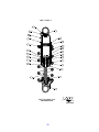
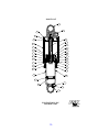
2001 VANILLA
22
21
23
24
17
16
18
19
20
15
11
10
13
14
9
12
7
6
5
8
4
2
3
1
FOX FACTORY, INC.
PROPRIETARY
32
33
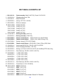
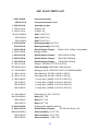
2001 VANILLA PARTS LIST
1. 213-07-023-A
Eyelet, Shaft [1.1438 TLG]
2. 008-01-005-A
Bumper: B/O [Ø.375 Shaft, .400 TLG] Nitrile
*3. 229-04-000-H
Shaft: [2.010 TLG]
229-15-003-B
Shaft: [2.655 TLG]
229-04-005-B
Shaft: [3.155 TLG]
229-15-006-B
Shaft: [3.405 TLG]
*4. 812-06-022-A
812-06-023-A
Bearing assembly: [.780 TLG]
Bearing assembly: [1.030 TLG]
5. 803-00-028-A
Damper rebuild kit part : (036-01-004-A U-cup, [Ø.375 Shaft])
6. 035-00-110-A
Seals: Q-Ring (-110)
7. 003-07-000-A
Bearing: Internal [.375 ID, Ø.375 Shaft]
8. 029-03-015-A
Seals: O-Ring (-020), Static
9. 008-00-002-A
Bumper: T/O [Ø.375 Shaft, .100 TLG] Nitrile
*10. 805-02-201-A
Piston: Damping: [.028 bleed, .220 TLG]
11. 002-02-005-A
Bearing: [0.135 W X 0.879 ID X 0.032 TH, Ø 0.940 Bore] PTFE, Blue, Ring
12. 050-01-012-A
Plate: Back-Up [.750 OD X .250 ID X .050 TH]
13. 050-01-011-A
Plate: Back-Up [.350 OD X .253 ID X .020 TH]
14. 044-04-080-A
1- Comp. Shim [.800OD X .252 ID X .0045 TH ]
044-04-070-A
1- Comp. Shim [.700OD X .252 ID X .0045 TH ]
044-04-060-A
1- Comp. Shim [.600OD X .252 ID X .0045 TH ]
044-04-050-A
1- Comp. Shim [.500OD X .252 ID X .0045 TH ]
15. 018-04-005-A
Fastener, Standard: Bolt [1/4-28 X .750 TLG], Socket Head
*16. 204-01-000-E
Body: One-Piece Clevis: [3.400 THG]
204-12-002-D
Body: One-Piece: [4.125 TLG]
204-12-004-D
Body: One-Piece: [4.625TLG]
204-12-007-D
Body: One-Piece: [5.000 TLG]
17. 805-00-005-A
Piston: Floating [Ø.940 Bore] Acetron GP
18. 803-00-051-A
Rebuild kit damper
19. 234-00-009-B
Preload Ring [1.740 OD X .300 TLG]
035-00-116-A Q-Ring (-116)
34
20.
21. 010-00-011-A
22. 010-00-010-A
Coil Springs - See spring chart ( travel and spring rates )
Pellet [Ø.275 X .125 TLG] Nitrile, Durometer 90A
Pellet Retainer Set Screw [5/16-24 X .220 TLG]
23. 010-01-003-A
24. 024-02-032-A
Ball [Ø.1875] Nylon
Vanilla Decal
OTHER NOTES:
# 803-00-028-A Damper rebuild kit
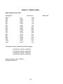
2000 Vanilla:
Damper charge 200 PSI Nitrogen
10 WT. Suspension fluid ( ISO 32 )
5.75” X 1.25” IFP settings 1.60”
6.5” X 1.50” IFP settings 2.00”
6.750” X 1.75” IFP settings 2.10”
7.500” X 2.00” IFP settings 2.40”
7.700” X 1.875” IFP settings 2.60”
7.875” X 2.00” IFP settings 2.60”
7.875” X 2.25” IFP settings 2.60”
Piston assembly 805-02-201-A .0280” bleed is smallest hole
size use as Pilot hole for tuning size according to Vanilla tuning
table
*Uncommon parts : Shock size specific
35
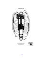
2001 VANILLA R
28
27
29
20
30
21
22
25
19
26
17
18
14
13
16
15
12
9
10
11
8
7
6
23
5
4
24
3
1
2
FOX FACTORY, INC.
PROPRIETARY
36
37
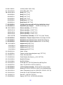
2001 VANILLA R PARTS LIST
1. 808-14-011-A
Eyelet assembly, Shaft [1.438 TLG] Eyelet 213-07-015-B
2. 210-03-016-A
Damping adjust knob - Red
3. 010-01-00-A
Ball [Ø.125] Steel
4. 039-00-003-A
Spring [.125 TLG X .125 OD]
5. 008-01-005-A
Bottom out bumper
*6. 229-27-002-B
Shaft [2.355 TLG]
229-27-003-B
Shaft [2.605 TLG]
229-27-004-B
Shaft [2.855 TLG]
229-27-005-B
Shaft [3.105 TLG]
229-27-006-B
Shaft [3.355 TLG]
*7. 812-06-005-A
812-06-023-A
Bearing assembly: [.665 TLG]
Bearing assembly: [1.030 TLG]
8. 803-00-028-A
Damper rebuild kit part :
036-01-004-A U-cup, [Ø.375 Shaft]
9. 803-00-028-A
Damper rebuild kit part :
035-00-110-A Seals: Q-Ring (-110)
10. 003-07-000-A
Bearing: Internal [.375 ID, Ø.375 Shaft]
11. 803-00-028-A
Damper rebuild kit part : 029-03-020-A Seals: O-Ring (-020), Static
12. 233-00-021-A
Spacer shaft [Ø.378 ID X .700 OD X .050 TLG] STEEL
13. 805-02-005-A
Piston Damping [Ø.940 Bore, .220 TLG]
14. 002-02-005-A
Bearing: [0.135 W X 0.879 ID X 0.032 TH, Ø 0.940 Bore] PTFE, Blue, Ring
15. 050-01-012-A
Plate: Back-Up [.700 OD X .252 ID X .050 TH]
16. 044-04-080-A
1- [.800 X .252 X .004]
044-04-070-A
1- [.700 X .252 X .004]
044-04-060-A
1- [.600 X .252 X .004]
044-04-050-A
1- [.500 X .252 X .004]
17. 044-10-060-A
4- [.600 X .252 X .010]
18. 050-01-011-A
Plate: Back-Up [.400 OD X .252 ID X .020 TH]
19. 290-90-016-A
Piston Bolt [1/4 –28 X .593 SHLG]
*20. 204-12-000-D
BODY [3.625 TLG]
204-12-001-D
BODY [3.875 TLG]
204-12-002-D
BODY [4.125 TLG]
204-12-004-D
BODY [4.750 TLG]
204-12-007-D
BODY [5.000 TLG]
204-47-001-A
BODY [4.425 TLG] SCHWINN STRAIGHT 6 TRUNION
38
21. 805-00-005-A
Piston: Floating [Ø.940 Bore]
22. 803-00-051-A
Rebuild kit damper
*23. 210-19-011-A
Metering Rods [2.455”]
035-00-116-A Q-Ring (-116)
210-19012-A
Metering Rod [2.705”]
210-19-013-A
Metering Rods [2.955”]
210-19-014-A
Metering Rods [3.205”]
210-19-015-A
Metering Rods [3.455”]
24. 029-05-105-A
O-ring [ .050 C.S. X 0.154 ID]
25. 234-00-009-B
Preload ring
26. See spring chart
27. 010-00-011-A
Pellet [Ø.275 X .125 TLG] Nitrile, Durometer 90A
28. 010-00-010-A
Pellet Retainer Set Screw [5/16-24 X .220 TLG]
29. 010-01-003-A
Ball [Ø.1875] Nylon
30. 024-02-033-A
Vanilla R Decal
OTHER NOTES:
# 803-00-028-A Damper rebuild kit
2001 Vanilla R:
Damper charge 200 PSI Nitrogen
10 WT. Suspension fluid ( ISO 32 )
5.75” X 1.25” IFP settings 1.60”
6.5” X 1.50” IFP settings 2.00”
6.750” X 1.75” IFP settings 2.10”
7.500” X 2.00” IFP settings 2.40”
7.700” X 1.875” IFP settings 2.60”
7.875” X 2.00” IFP settings 2.60”
7.875” X 2.25” IFP settings 2.60”
*Un-common parts : Shock size specific
39
2001 VANILLA RC
29
5
27
26
4
24
3
28
25
30
45
20
43
23
40
26
42
41
39
44
19
19
17
22
18
21
14
48
13
33
16
15
34
12
38
10
9
35
11
36
8
6
37
7
31
5
46
47
4
32
3
2
1
FOX FACTORY, INC.
PROPRIETARY
40
41
2001 VANILLA RC PARTS LIST
1. 808-14-026-A
Eyelet assembly, Shaft [1.190 TLG] Eyelet 213-07-0035-A
2. 210-03-016-A
Damping adjust knob - Red
3. 010-01-00-A
Ball [Ø.125] Steel
4. 039-00-003-A
Spring [.125 TLG X .125 OD]
5. 008-01-005-A
Bottom out bumper
*6. 229-27-002-B
Shaft [2.355 TLG]
229-27-003-B
Shaft [2.605 TLG]
229-27-004-B
Shaft [2.855 TLG]
229-27-005-B
Shaft [3.105 TLG]
229-27-006-B
Shaft [3.355 TLG]
229-27-007-B
Shaft [3.605 TLG]
229-27-008-B
Shaft [3.855 TLG
229-27-009-B
Shaft [4.105 TLG]
*7. 812-06-011-A
812-06-012-A
Bearing assembly: [.665 TLG]
Bearing assembly: [1.030 TLG]
8. 803-00-028-A
Damper rebuild kit part :
036-01-004-A U-cup, [Ø.375 Shaft]
9. 029-02-110-A
Seals: O-Ring urethane(-110)
10. 003-07-000-A
Bearing: Internal [.375 ID, Ø.375 Shaft]
11. 803-00-028-A
Damper rebuild kit part : Seals: O-Ring (-020), Static 029-03-015-A
12. 233-00-021-A
Spacer shaft [Ø.378 ID X .700 OD X .100 TLG] Steel
*13. 805-02-005-A
805-02-004-A
Piston Damping [Ø.940 Bore, .220 TLG]
Piston Damping Downhill Hi Flow [Ø.940 Bore, .315 TLG]
14. 002-02-005-A
Bearing: [ .050 C.S. X 0.154 ID] PTFE, Blue, Ring
15. 050-01-012-A
Plate: Back-Up [.700 OD X .252 ID X .050 TH]
16. 044-04-080-A
1- [.800 X .252 X .004]
044-04-070-A
1- [.700 X .252 X .004]
044-04-060-A
1- [.600 X .252 X .004]
044-04-050-A
1- [.500 X .252 X .004]
17. 044-10-060-A
4- [.600 X .252 X .010]
18 050-01-011-A
Plate: Back-Up [.400 OD X .252 ID X .020 TH]
19. 290-90-016-A
Piston Bolt [1/4 –28 X .593 SHLG]
*20. 204-05-003-G
BODY [2.930 TLG]
204-05-018-D
BODY [3.180 TLG]
42
204-05-004-G
BODY [3.430 TLG]
204-05-005-G
BODY [3.680 TLG]
204-05-019-G
BODY [3.805 TLG]
204-05-021-G
BODY [4.180 TLG]
204-05-020-G
BODY [4.405 TLG]
204-05-023-G
BODY [4.680 TLG]
21. [ .050 C.S. X 0.154 ID]
22. 803-00-051-A
Rebuild kit damper
23. 234-00-009-B
Preload ring Stanadard for 1.25” spring ID
234-00-038-A
*24. 804-01-016-A
035-00-116-A Q-Ring (-116)
Preload ring Downhill Heavy Duty for 1.375” spring ID
Piggyback Body cap assembly:
206-03-013-A
RC Body end cap
206-03-011-B
RX Body end cap
25. 803-00-051-A
Rebuild kit damper
02-03-023-A O-ring (-023)
26. 210-15-016-A
Check valve
27. 039-00-009-A
Spring [.280 TLG X .108 OD]
28. 210-03-018-A
Compression adjuster knob (blue)
29. 029-00-009-A
O-ring (-009)
30. 018-01-007-A
Socket set screw [8-32 X .250 TLG]
*31. 210-19-012-A
Metering Rod [2.705” TLG]
210-19-013-A
Metering Rod [2.955” TLG]
210-19-015-A
Metering Rod [3.455” TLG]
210-19-016-A
Metering Rod [3.705” TLG]
210-19-017-A
Metering Rod [3.955” TLG]
210-19-018-A
Metering Rod [4.205” TLG]
32. 029-05-105-A
O-ring [ .050 C.S. X 0.154 ID]
33. 227-09-004-B
Reservoir : Cap Style [2.030 TLG]
34. 813-00-021-A
Assembly: Reservoir end cap with pellet / retainer
226-00-009-B
Res. End Cap.
35. 010-00-011-A
Pellet [Ø.275 X .125 TLG] Nitrile, Durometer 90A
36. 010-00-010-A
Pellet Retainer Set Screw [5/16-24 X .220 TLG]
37. 010-01-003-A
Ball [Ø.1875] Nylon
38. 029-03-020-A
O-ring (-020)
39. 222-01-015-B
Damping : Reservoir compression piston
40. 029-03-019-A
O-ring (-019)
41. 210-10-009-A
2001 Reservoir compression piston bolt [.116 orifice high flow]
43
42. 018-00-009-A
Nut [1/4-24 X .450 SHLG]
43. 044-04-060-A
Valving 1-[.600 OD X .252 X .0045]
44. 044-20-060-A
Valving 4- [.600 OD X .252 X .020]
45. 029-02-009-A
O-ring (-009) Polyurethane
46. See spring charts
47. 234-00-008-E
234-00-069-A
48. 024-02-034-A
Spring retainer Standard for 1.25” spring ID
Spring retainer Downhill Heavy Duty for 1.375” spring ID
Decal
Other Notes:
# 803-00-028-A Damper rebuild kit
IFP 200 PSI
Oil 10 wt. ( ISO 32 )
*Un-common parts : Shock size specific
44
45
VANILLA AND VANILLA R
SERVICE
INSTRUCTIONS
46
47
Vanilla hand dyno figure 6.1
A. Diagnosis
1)
2)
Clean shock with contact cleaner to remove all dirt and oil.
Remove reducers and bushings (if used).
Hand Dyno Vanilla
1)
2)
3)
Install appropriate spring on damper (check spring table if necessary).
Install shock in dyno. (fig. 6.1)
Compress shock and let return freely several times.
·
Watch shock rebound.
If shock compresses and does not return there may be something clogging the bleed hole.
If shock extends very quickly and makes a squealing noise on extension
the shock may have lost nitrogen pressure.
·
Listen for squeals on rebound.
Loud squeals indicate air mixed with oil.
This could be inadequate bleeding when the shock was built or a leaking
IFP.
·
·
·
·
Listen for loud squeaks.
This could be the spring rubbing on the body.
Check for excessive friction on rebound.
Sticky shaft stroke may indicate a tight bearing.
Listen for zipper noises inside shock body.
These noises may indicate a surface finish problem on the bore of the
shock body.
Feel for hard top out.
Hard top out can be caused by a damaged top out bumper.
NOTE: You may find from time to that the Top out pad is deformed or has been
smashed into damper piston causing the shock to become stuck down.
Replace top out pad with a new one P/N 008-00-002-A and make sure
the bearing housing is the cup type. Correct Bearing housing is P/N 81206-022-A TLG .780” and 812-06-023-A TLG 1.030”.
48
Hand Dyno Vanilla R
1)
2)
3)
4)
5)
6)
7)
8)
Hand dyno Vanilla R figure 6.1a
Install appropriate spring on damper (check spring table if necessary).
Install shock in dyno. (figure 6.1a)
Set rebound adjuster knob (red) to full fast position (all the way counter clockwise).
Compress shock and let return freely several times.
·
Listen for loud squeaks. This could be the spring rubbing on the body.
·
If shock compresses and does not return there may be something clogging the
shaft
bleed hole or the metering rod may be damaged or stuck.
Adjust rebound adjuster knob (red) clockwise to full slow.
Compress shock and let return freely several times.
·
The shock should rebound very slowly at this setting.
If shock rebounds quickly the valves may be damaged. Check seal
between metering rod, shaft and piston bolt.
·
Watch shock rebound.
If shock extends very quickly and makes a squealing noise on extension
the shock may have lost nitrogen pressure.
Next check the middle of the rebound range by turning the rebound adjuster knob (red)
counter clockwise six clicks.
Compress shock and let return freely several times.
·
There should be a substantial increase in rebound speed from the fully closed
position. If not check the valves for damage.
·
Listen for squeals on rebound.
Loud squeals indicate air mixed with oil.
This could be air trapped in oil when the shock was built or a leaking IFP.
This could also could be caused by a bur on the piston,piston bolt or shaft
bleed hole.
·
Check for excessive friction on rebound.
Sticky areas may indicate a tight bearing.
·
Listen for zipper noises inside shock body.
These noises may indicate a surface finish problem on the bore of the
shock body.
·
Feel for hard top out.
Hard top out can be caused by a problem with the hydraulic top out
(check the shaft groove above rebound bleed hole). Check for undersized
piston glide ring also.
49
Spring preload adjuster figure 6.2
Spring Removal
1)
2)
3)
4)
Clamp shock body eyelet in vice with soft jaws.
Turn spring preload adjuster ring counter clockwise and unthread completely from
shock body. ( fig. 6.2)
Remove shock from vice.
Slide preload adjuster ring and spring off of shock.
50
15/16” loosen bearing figure 6.3
Blow IFP into a rag figure 6.4
Shaft Assembly Removal and IFP Removal
1)
2)
3)
4)
5)
6)
7)
8)
9)
Vanilla R only: Open rebound knob all the way fast (counter clockwise) so oil will drain
when removing shaft assembly.
Remove nylon ball from threaded pellet retainer hex with a dental pick.
Unthread socket hex pellet retainer to release nitrogen pressure.
· NOTE: For older press in pellet retainer shocks (this type has no socket hex feature to
unscew). Release nitrogen charge through the pellet hole with filler needle.
Remove threaded pellet retainer and pellet.
Clamp body eyelet in vice.
Using a 15/16 open end wrench carefully loosen the aluminum bearing housing.(figure
6.3)
·
Note: If it takes excessive force to loosen the bearing the shock may still have
nitrogen pressure inside it. Unscrew the bearing housing a few turns and let
pressure dissipate for several minutes before going any further.
Loosen bearing completely and carefully work the shaft assembly up and out of the
shock body and set aside on lint free towel.
Carefully remove body from vice and dump oil into your waste oil container.
IFP ( Internal Floating Piston ) removal.
·
Blow IFP into a rag by pressurizing shock body through the pellet hole with
pressurized air. (firgure 6.4)
51
Removal of 3/8” Piston bolt figure 6.5
Piston Removal
1)
2)
3)
4)
5)
6)
7)
8)
Clean shaft assembly with contact cleaner.
Clamp eyelet in vice. Do not smash rebound adjuster knob (red).
Vanilla: Remove piston bolt with 3/16” Allen wrench.
Vanilla R: Remove piston bolt with 3/8” open end wrench. (figure 6.5)
Remove piston, valves, and top out plate and set on lint free towel.
Remove bearing assembly and spacer (if used).
Remove bottom out bumper.
Remove eyelet and shaft assembly from vice.
Inspect shaft for any nicks, pits, wear marks, or damage.
·
If the shaft fails inspection replace it as described in Vanilla Shaft Replacement
section.
52
Warm with torch to soften Loctite
figure 6.6
1/2” Bar in eyelet figure 6.7
Vanilla Shaft Replacement
1)
2)
3)
4)
5)
6)
7)
Spray shaft and Ø .375 shaft clamps with contact cleaner and clamp shaft in vise wet
using Ø .375 shaft clamps to hold shaft securely in the vise.
Use a small propane torch to heat the shaft at the eyelet, this will soften the Loctite and
allow the eyelet to be removed easily. (figure 6.6)
Slide a Ø 1/2 inch breaker bar through the eyelet and turn counter clockwise to
remove.(figure 6.7)
Clean eyelet and shaft thoroughly of any old Loctite.
Clamp shaft in vice.
Lay a bead of red Loctite around the base of the shafts threads.
Torque eyelet to shaft using eyelet torque wrench (see Torque Tables for proper torque).
53
Metering rod O-ring figure 6.8
Loctite Shaft threads figure 6.9
Vanilla R Shaft Replacement
1)
2)
3)
4)
5)
6)
7)
8)
9)
Spray shaft and Ø .375 shaft clamps with contact cleaner and clamp shaft in vise using
Ø .375 shaft clamps to hold shaft securely in the vise.
Use a small propane torch to heat the shaft at the eyelet, this will soften the Loctite and
allow the eyelet to be removed easily.
Slide a Ø 1/2 inch breaker bar through the eyelet and turn counter clockwise to remove.
If rebound adjuster knob is damaged rebuild eyelet assembly:
·
Turn rebound adjuster knob clockwise to remove.
·
Remove spring and Ball from red knob.
·
Grease knob at threads,taper and spring hole.
·
Insert ball and spring into rebound knob hole.
·
Install rebound adjuster knob by turning all the way counterclockwise then clockwise until the edge of the small ball is visible.
Remove metering rod and inspect for damage, replace seal.
Replace metering rod o-ring in the shaff and grease (figure 6.8)
Lay a bead of red Loctite around the base of the shafts threads. Keep Loctite away
from metering rod! (figure 6.9)
Using shaft clamps clamp the shaft in vice.
Torque eyelet to shaft using eyelet torque wrench (see Torque Tables for proper torque).
Shaft Torque Tip: Use piston bolt with 4 back up plates (.093” thick) and thread into shaft,
clamp eyelet in vise and torque bolt . Be careful when removing bolt as shaft may turn, if this
happens re torque and clamp shaft in vise with shaft clamps before removing bolt.
54
Picking out dust wiper figure 6.10
Installing shaft seal figure 6.11
Bearing Assembly
1)
With dental pick carefully pick out dust wiper seal from the shaft bearing housing.
(figure 6.10)
2)
With dental pick carefully pick out out the shock shaft seal.
3)
With dental pick carefully pick off the bearing housing outer threads o-ring.
4)
Inspect the bearing by sliding the bearing assembly with seals removed along the
shaft. You are checking for excessive clearance and wear.
5)
Install a new shaft seal in the bearing housing.
·
Slide seal into the groove from the bearing end.
·
Press remainder of shaft seal into groove. (figure 6.11)
NOTE: Make sure that the shaft quad ring or O-ring is not twisted and that it is seated completely in its groove.
6)
Replace dust wiper seal in the top groove.
7)
Replace bearing housing outer O-ring.
8)
Set completed bearing assembly aside on lint free towel.
55
Installing quad ring seal
figure 6.13
Removing quad ring seal
figure 6.12
IFP Seal Replacement
1)
2)
3)
Carefully use a picking tool to remove the quad ring seal from the groove in the IFP.
(figure 6.12)
Use extreme caution with picking tool as the IFP is plastic and will damage
easily.
Inspect IFP for damage and make sure the piston groove has no scratches or nicks.
Replace if necessary.
To install your new quad ring place one side of quad ring into groove and stretch the
quad ring around the IFP snapping it into the groove. (figure 6.13)
·
Make sure the Q ring is not twisted and is seated in the ring groove correctly.
IFP Installation
1)
2)
3)
4)
5)
Clean inside of shock body with contact cleaner and inspect for scratches or wear.
Replace body if necessary.
Grease quad ring on IFP.
Grease Threads of Body.
Insert greased IFP into body pocket side up. (Use IFP depth table for proper IFP setting).
Set aside for final assembly.
56
Piston bolt to torque figure 6.14
Vanilla Shaft Assembly
1)
2)
3)
4)
5)
6)
7)
8)
9)
Slide bottom out bumper onto shaft and eye assembly.
Install shaft bullet tool.
Grease dust wiper, Q-ring and inside of bearing.
Slide Bearing assembly over bullet tool and onto shaft.
Remove bullet tool.
Clamp eyelet in vice.
Refer to tuning tables for appropriate bleed hole size if necessary.
·
Replace compression valves.
·
Make sure piston and valves are clean and bur free.
Take fresh piston assembly and thread piston bolt into shaft.
Torque piston bolt to torque specified in torque tables. (figure 6.14)
57
Piston bolt torque
figure 6.14
Vanilla R Shaft Assembly
1)
2)
3)
4)
5)
6)
7)
8)
9)
10)
Checking rebound clicks
figure 6.15
Slide bottom out bumper onto shaft and eye assembly.
Grease seals and inside of bearing.
Slide bearing assembly onto shaft. (Adjustable Vanilla shafts have a generous radius
so bullet tool is not needed.)
Clamp eyelet in vice.
Refer to tuning tables for appropriate valve stack if necessary.
·
Replace compression valves.
·
Make sure piston and valves are clean and bur free.
Take fresh piston assembly and thread piston bolt into shaft.
Torque piston bolt to torque specified in torque tables.(figure 6.14)
Check the number of rebound adjuster clicks.(figure 6.15)
·
Count the number of clicks it takes to go from all the way closed rebound bleed
to
all the way open rebound bleed. Shock should have at least 12-18 clicks
of rebound.
(clicks may vary because of shim stack thickness)
·
Close the rebound bleed by turning the rebound adjuster knob (red) all the way
clockwise while using an Allen key to press up on the metering rod.
·
Open the rebound bleed by turning the rebound adjuster knob (red) all the way
counterclockwise while pressing on the metering rod with an Allen key.
·
Leave the rebound bleed all the way open so that air is not trapped in the oil
during final assembly.
Adjust the number of clicks.
·
If you need more clicks you can add one .400 x .010 compression valve spacer.
·
If you need less clicks you can replace the .400 x .010 compression valve with
one .400X.010 Compression valve spacer.
Set aside on lint free towel for final assembly.
58
Torque bearing assembly figure 6.17
Bleeding oil out figure 6.16
Mating Shaft Assembly to Body
1)
2)
3)
4)
5)
6)
7)
8)
9)
10)
11)
12)
13)
Place IFP set tool at predetermined height and slide body over it. Press down on IFP to
make sure it is seated at the correct height. ( or use Calipers to set proper height)
Fill body with oil up to the middle thread.
Clamp body eyelet in vice.
Vanilla R: Make sure that the rebound adjuster knob (red) is all the way counter clockwise.
Slide bearing assembly down to the top of rebound hole.
Insert shaft assembly into body by carefully rocking back and forth to remove air
bubbles from the oil and thread into body. (figure 6.16)
Tighten bearing assembly. Torque to specification shown in torque specification table.
(figure 6.17)
Install 90 durometer pellet in body.
Tighten pellet retainer with torque wrench screwdriver to initial torque setting shown in
torque table.
Charge shock with two hundred psi of nitrogen.
Tighten pellet retainer with torque wrench screwdriver to final torque setting shown in
torque table.
Push in damper all the way by hand.
·
If damper does not get full travel or gets very difficult to compress, nitrogen
chamber may be too small and damper will need to be refilled. Usually this is
caused by IFP moving during assembly.
·
If piston hits IFP nitrogen chamber may be too large and damper will need to be
refilled.
Do an air leak test.
59
Preload adjuster figure 6.18
Spring Installation
1)
2)
3)
4)
Slide spring over damper.
Thread preload adjuster onto body.
Tighten preload adjuster one half turn past snug. (figure 6.18)
Hand dyno. (6.19)
Hand dyno figure 6.19
60
61
VANNILLA RX AND RC
SERVICE INSTRUCTIONS
62
63
64
A. Diagnosis
1)
2)
Vanilla RC in hand dydno figure 7.1
Clean shock with cleaner to remove all dirt and oil.
Remove reducers and bushings (if used).
Hand Dyno Vanilla RC
1)
2)
3)
4)
5)
6)
7)
8)
9)
Install appropriate spring on damper.
Install shock into your hand dyno. (figure 7.1)
Set rebound adjuster knob (red) to full fast position (all the way counter clockwise).
Set compression adjuster knob (blue) to softest position (all the way counter clockwise).
Compress shock and let return freely several times.
·
If shock compresses and does not return there may be something clogging the
shaft bleed hole or the metering rod may be damaged or stuck.
·
Listen for loud squeaks. This could be the spring rubbing on the body.
Adjust rebound adjuster knob (red) clockwise to full slow.
Compress shock and let return freely several times.
·
The shock should rebound very slowly at this setting.
If shock rebounds quickly the valves may be damaged. Check the fit between
metering rod, shaft and piston bolt.
·
Watch shock rebound.
If shock extends very quickly and makes excessive noise on extension the shock
may have lost nitrogen pressure or shock oil has excessive air in oil.
Next check the middle of the rebound range by turning the rebound adjuster knob (red)
counter clockwise six clicks.
Compress shock and let return freely several times.
·
There should be a substantial increase in rebound speed from the fully closed
65
RC body end cap in vise
figure 7.3
Untread pellet retainer figure 7.2
·
·
posi
tion. If not check the shock compression / rebound valves.
Listen for squeals on rebound.
Loud squeals indicate air mixed in with oil.
This could be a inadequate bleeding when the shock was built or a leaking IFP.
This could
also be caused by a bur on the piston or piston bolt.
Check for excessive friction on rebound.
Sticky areas may indicate a tight piston bearing.
·
10)
11)
Listen for zipper noises inside shock body.
These noises may indicate a surface finish problem on the bore of the shock
body.
·
Feel for hard top out.
Hard top out can be caused by a problem with the hydraulic top out
(check the shock shaft top out rebound bleed groove and undersized glide ring ).
Turn compression adjuster knob (blue) six clicks clockwise (harder).
·
Hand feel compression stroke it should become harder.
Turn compression adjuster knob (blue) all the way clockwise (hardest).
·
Hand feel compression it should become very hard.
·
If compression is not becoming harder check reservoir damping piston and
check all valves and compression adjuster check valve for proper seal ( facing
surface ).
If valves are not laying flat on the reservoir damping piston, flat sand the reservoir
damping piston and replace valves. Check for nics on the sealing surface for
check valve in bodycap.
66
B. Disassembly
Spring Removal
1)
2)
3)
4)
5)
Removing piston bolt figure 7.4
Clamp shock body eyelet in your vice with soft jaws.
Turn spring preload adjuster ring counter clockwise and unthread to loosen spring.
Remove slotted spring retainer
Remove Spring
Remove shock from vice.
Shaft Assembly Removal and IFP Removal
1)
Open rebound adjuster knob (red) all the way fast (counter clockwise) so that oil will
drain when removing shaft assembly.
2)
Remove nylon ball from threaded pellet retainer hex with a the dental pick.
3)
Unthread threaded pellet retainer to release nitrogen pressure.(figure 7.2)
·
Wear Safety Glasses when you remove rubber pellet, oil may squirt out.
·
Note : Release nitrogen charge with filler needle for old 99’ press in pellet retainer.
4)
Clamp body cap eyelet into soft jaw vice. (figure 7.3)
5)
Loosen the reservoir from the body cap by turning the reservoir end cap counter clockwise.
·
Note: If it takes excessive force to loosen the reservoir the contents may be
under pressure. Open a few turns and let pressure dissipate for several minutes.
6)
Using a 15/16 open end wrench loosen the bearing assembly from the body shock
body.
7)
Unthread reservoir the rest of the way from body cap and pour oil into waste oil container.
8)
Push IFP and Compression damping piston (used on Vanilla RC) out of reservoir.
9)
Clamp shock body in body clamps with vise.
10)
Carefully remove bearing assembly and dump remaining oil into waste oil container.
11)
Clamp shock body in vise and remove the body cap from form shock body.
12)
Remove the body from vice.
67
1/2” Bar to remove eyelet figure
7.6
Torch eyelet to soften Loctite figure
7.5
Piston Removal
1)
2)
3)
4)
5)
6)
7)
8)
Clean shaft assembly with contact cleaner.
Clamp eyelet in vice. Do not smash rebound adjuster knob (red).
Remove piston bolt with 3/8” open end wrench. (figure 7.4)
Remove piston, valves, and top out plate and set on lint free towel.
Remove bearing assembly and spacer.
Remove bottom out bumper.
Remove eyelet and shaft assembly from vice.
Inspect shaft for any nicks, pits, wear marks, or damage.
·
If the shaft fails inspection replace it as described in Vanilla RC Shaft Replacement section.
68
Taking out dust wiper seal figure 7.7
Vanilla RC Shaft Replacement
1. Spray shaft and Ø .375 shaft clamps with contact cleaner and clamp shaft in vise wet
using Ø .375 shaft clamps to hold shaft securely in the vise.
2. Use a small propane torch to heat the shaft at the eyelet, this will soften the Loctite and
allow the eyelet to be removed easily. (figure 7.5)
3. Slide a Ø 1/2 inch breaker bar through the eyelet and turn counter clockwise to
remove.(figure 7.6)
4. If rebound adjuster knob is damaged you should rebuild eyelet assembly.
5. Turn rebound adjuster knob clockwise to remove.
6. Remove spring and Ball from red knob.
7. Grease knob at taper,threads and spring hole.
a. Insert ball and spring into rebound knob hole.
8. Install rebound adjuster knob by turning clockwise several turns.
9. Remove metering rod and inspect for damage.
10. Replace metering rod o-ring in shaft.
11. Lay a bead of red Loctite around the base of the shafts threads. Keep Loctite away
from metering rod!
12. Clamp shaft in vice.
13. Torque eyelet to shaft using eyelet torque wrench (see Torque Tables for proper torque).
Shaft Torque Tip: Use piston bolt with 4 back up plates (.093” thick) and thread into shaft,
clamp eyelet in vise and torque bolt . Be careful when removing bolt as shaft may turn, if this
happens re torque and clamp shaft in vise with shaft clamps before removing bolt.
69
Installing Q-ring
figure 7.9
Removing Q-ring
figure 7.8
Bearing Assembly
1)
2)
3)
4)
Pick out the wiper seal.(figure 7.7)
Pick out the polyurethane O-ring for Vanilla RC.
Pick off the O-ring by the bearing housing outer threads.
Inspect the bearing by sliding the bearing assembly with seals removed along the
shaft. You are checking for clearance and wear.
·
The bearing should slide freely. If you feel excessive friction the bearing assembly should be replaced.
5)
Install a new seal polyurethane O-ring in the top groove of the bearing housing.
·
Slide seal into the groove from the bearing end.
·
Press remainder of seal into groove with seal installation tool.
NOTE: Make sure that the seal is not twisted and that it is seated completely in its groove.
6)
Replace wiper seal.
7)
Replace bearing housing outer O-ring.
8)
Set completed bearing assembly aside on lint free towel.
figure 7.10
70
Checking rebound clicks
figure 7.12
Torquing piston bolt
figure 7.11
IFP Seal Replacement
1)
2)
3)
Carefully use a picking tool to remove the quad ring seal from the quad ring groove in
the IFP ( Internal Floating Piston). Use caution with picking tool as the IFP is plastic and
will scratch and damage easily. (figure 7.8)
Inspect IFP for damage. Replace if necessary.
To install your new quad ring place one side of quad ring into groove in IFP and stretch
the quad ring around the IFP snapping it into the groove. (figure 7.9)
·
Make sure the Q ring is not twisted and is seated in the quad ring groove.
IFP Installation
1)
2)
3)
4)
Clean inside of reservoir with contact cleaner and inspect for scratches or wear.
·
Replace reservoir if necessary.
Grease quad ring on IFP.
Grease internal threads of reservoir.
Insert greased IFP into reservoir cup side down towards oil side. (figure 7.10)
71
Body cap in vise figure 7.13
Pushing oil through body cap
figure 7.14
Vanilla RC Shaft Assembly
1)
2)
3)
Slide bottom out bumper onto shaft and eye assembly.
Grease seals and inside of bearing.
Slide bearing assembly onto shaft. (Adjustable Vanilla shafts have a generous radius so
bullet tool is not needed).
4)
Clamp eyelet in vice.
5)
Refer to tuning tables for appropriate valve stack if necessary.
·
Replace compression valves .
·
Make sure piston and valves are clean and bur free.
6)
Take fresh piston assembly and thread piston bolt into shaft.
7)
Torque piston bolt to torque specified in torque tables.(figure 7.11)
8)
Check the number of rebound adjuster clicks.(figure 7.12)
Shock must have 12-18 clicks of rebound.
·
Count the number of clicks it takes to go from all the way closed rebound bleed to
all the way open rebound bleed.
·
Close the rebound bleed by turning the rebound adjuster knob (red) all the way
clockwise while using an Allen key to press up on the metering rod.
·
Open the rebound bleed by turning the rebound adjuster knob (red) all the way
counterclockwise while pressing on the metering rod with an Allen key.
·
Leave the rebound bleed all the way open so that air is not trapped in the oil
during final assembly.
9)
Adjust the number of clicks.
·
If you need more clicks you can add one .400 x .010 compression spacer.
·
If you need less clicks you can remove .400 X .020 compression spacer with one
.400 X .010 compression valve spacer.
10)
Set aside on lint free towel for final assembly.
72
Installing shaft assembly
figure 7.15
Bleeding Shock
1)
2)
3)
4)
5)
6)
7)
8)
9)
10)
11)
12)
13)
14)
15)
16)
Thread preload ring onto body.
Thread body cap eyelet onto body.
Clamp body cap eyelet in vice.(figure 7.13)
Fill body cap with oil up to the middle thread.
Turn compression adjuster knob (blue) in and out until bubbles stop appearing.
Fill reservoir with oil.
Insert reservoir damping piston into reservoir. Note: Be careful oil can squirt out
into your face.
Thread reservoir onto body cap.
Remove shock from vice.
Turn compression adjuster knob (blue) all the way counter clockwise ( soft setting ).
While pushing on IFP so that oil is flowing through body cap rotate body and reservoir
assembly such that the body is above the reservoir.(figure 7.14) Note: Be
careful oil can squirt out onto your shoes ect..ect.
·
This will force all of the air out of the reservoir and body cap leaving only pure oil.
Pour oil into the body up to the middle of bearing housing threads.
Make sure that the rebound adjuster knob (red) is all the way counter clockwise (fastest
setting) on your shaft assembly.
Open metering rod by pushing up into the piston bolt hole with a small Allen key.
Hold the IFP down with a blunt rounded tipped tool.
Insert shaft assembly into body by carefully rocking back and forth to remove air
bubbles from the oil. (figure 7.15)
73
Torquing Bearing housing
figure7.16
Torquing pellet filler screw
figure 7.18
Torquing resorvoir cap
figure7.17
200 PSI Nitrogen charge
figure 7.19
Torquing and Pressurizing
1)
2)
3)
4)
5)
6)
7)
8)
9)
Slide bearing assembly down and thread into body.
Tighten bearing assembly. Torque to specification shown in torque specification
table.(figure7.16)
Tread reservoir end cap into reservoir. Torque to specification shown in torque specification table. (figure7.17)
Install 90 durometer pellet in resorvoir body cap with pellet retainer.
Tighten pellet retainer with torque wrench screwdriver to initial torque setting shown in
torque table.(figure 7.18)
Charge shock with two hundred psi of nitrogen.(figure 7.19)
Tighten pellet retainer with torque wrench screwdriver to final torque setting shown in
torque table.
Push in damper all the way by hand.
·
If damper does not get full travel or gets very difficult to compress, nitrogen
chamber may be too small and damper will need to be rebuilt again. Usually
this is caused by IFP moving during assembly. The shock shaft should also
return back to full extension after charging with Nitrogen with the rebound knob
is full open counter clockwise ( fast ).
Do an air leak test.
74
Spring Collar Installation.
Spring Installation
1)
2)
3)
4)
Slide spring over damper body.
Slide slotted spring retainer onto eyelet. (figure 7.20)
Tighten preload adjuster one half turn past snug.
Hand dyno.(figure 7.21)
Installing spring retainer
figure 7.20
Kevin Blair using the hand dyno figure 7.21
75
FLOAT DRAWINGS
AND PART LIST
76
77
78
2001 FLOAT
1
2
3
12
5
4
33
22
7
30
6
8
26
31
9
15
16
17
11
14
10
18
13
25
24
23
19
32
21
29
20
28
27
FOX FACTORY, INC.
PROPRIETARY
79
80
2001 FLOAT PARTS LIST
1. 808-14-028-A
808-14-031-A
Float eyelet Assembly
Float eyelet Assembly Trunion
2. 802-00-001-A
Assembly air valve
3. 029-03-126-A
O-Ring 2-126
4. 029-03-110-A
O-Ring 2-110
*5. 229-15-009-B
Shaft [ 1.905 TLG ]
229-15-001-B
Shaft [ 2.405 TLG ]
229-15-005-B
Shaft [ 3.155 TLG ]
6. 812-06-020-A
812-06-021-A
Bearing assembly [.815 TLG]
Bearing assembly [1.065 TLG]
7. 803-00-051-A
Rebuild kit part, Damper
029-02-110-A O-Ring - Polyurethane
8. 003-07-000-A
Bearing, Internal
9. 803-00-051-A
Rebuild kit part, Damper
029-03-023-A O-Ring
10. 803-00-051-A
Rebuild kit part, Damper
002-02-007-A Bearing
11. 803-00-051-A
Rebuild kit part, Damper
035-00-218-A Q-Ring
12. 040-15-110-A
Valve: [1.100 OD X .377 ID X .015 TH]
*13. 805-02-101-A
Piston assembly .0280” bleed / Pilot hole size
14. 002-02-005-A
Bearing [0.135 W X 0.879 ID X 0.032 TH, Ø 0.940 Bore] Blue
15. 050-01-012-A
Plate: Back-Up [.750 OD X .250 ID X .050 TH]
16. 050-01-011-A
Plate: Back-Up [.350 OD X .253 ID X .020 TH]
17. 044-04-080-A
1- Comp. Shim [.800OD X .252 ID X .0045 TH ]
044-04-070-A
1- Comp. Shim [.700OD X .252 ID X .0045 TH ]
044-04-060-A
1- Comp. Shim [.600OD X .252 ID X .0045 TH ]
044-04-050-A
1- Comp. Shim [.500OD X .252 ID X .0045 TH ]
18. 018-04-005-A
Piston Bolt [1/4 –28 X .750 TLG]
*19. 204-54-005-A
Body 3.687” TLG,
204-54-006-A
Body 4.312” TLG,
204-54-007-A
Body 3.187” TLG,
20. 805-00-005-A
Floating piston assembly w/Q-ring
21. 803-00-051-A
Rebuild kit part, Damper
*22. 806-29-000-A
Sleeve assembly : 2.710” TLG
806-29-002-A
Sleeve assembly : 3.210” TLG
806-29-004-A
Sleeve assembly : 3.960” TLG
81
035-00-116-A Q-ring -116
806-15-007-B
Sleeve assembly : Trunion 3.210” TLG
23. 803-00-050-A
Rebuild kit - Float air sleeve 036-02-014-A Wiper Ø1.060
24. 803-00-050-A
Rebuild kit part, Float air sleeve 003-09-000-A Bearing: 2X
25. 803-00-050-A
Rebuild kit part, Float air sleeve 035-01-215-A Q-Ring,
26. 233-00-009-B
Spacer shaft [.378 ID X .700 OD X .100 TLG]
27. 010-00-011-A
Pellet, Durometer 90A
28. 010-00-010-A
Pellet Retainer Set Screw [5/16-24 X .220 TLG]
29. 010-01-003-A
Ball [Ø.1875] Nylon
30. 018-01-007-A
Screw [#8-32 X .250 TLG] Socket Set Half Dog Point
31. 010-01-000-A
Ball [Ø.125] Steel
32. 029-03-022-A
O-Ring (-022), Static
*33. 024-02-035-A
Decal
024-02-038-A
Decal Trunion
OTHER NOTES:
#803-00-050-A
Air sleeve rebuild kit
# 803-00-051-A Damper rebuild kit
2000 Float:
Damper charge 200 PSI Nitrogen
Oil 10wt (ISO 32)
Sizes :
5.5” X 1.00” IFP settings 1.40”
6.5” X 1.5” IFP settings 1.850”
6.37” X 1.5” IFP settings 1.850” (Trunion) Cannondale
6.55” X 1.5” IFP settings 1.850” ( strut )
7.875” X 2” IFP settings 2.500”
7.925” X 2” IFP settings 2.500” ( strut )
Piston assembly 805-02-101-A .0280 Bleed hole (use as pilot for larger hole
size for tuning
* Un-common parts : Shock size specific or tuning spec.
82
2001 FLOAT R
1
2
5
4
32
6
3
7
8
16
9
31
40
27
11
38
10
37
12
33
13
19
15
20
14
22
18
30
17
29
21
23
28
39
26
24
25
36
35
34
FOX FACTORY, INC.
PROPRIETARY
83
84
2001 FLOAT R PARTS LIST
1. 808-14-029-A
808-14-032-A
Float R Eyelet Assembly
Float R Eyelet Assembly Trunion
2. 802-00-001-A
Assembly air valve
3. 029-03-126-A
O-Ring 2-126
4. 210-03-016-A
Red Knob, RD adjuster
5. 010-01-000-A
Ball [Ø.125] steel
6. 039-00-003-A
Spring [ .190 TLG X .120 OD ]
7. 029-03-011-A
O-Ring – 2-011
8. 029-03-110-A
O-Ring 2-110
*9. 229-27-000-B
Shaft [1.855 TLG]
229-27-001-B
Shaft [2.105 TLG]
229-27-002-B
Shaft [2.355 TLG]
229-27-005-B
Shaft [3.105 TLG]
10. 812-06-020-A
812-06-021-A
Bearing assembly [.815 TLG]
Bearing assembly [1.065 TLG]
11. 803-00-051-A
Rebuild kit part, Damper
029-02-110-A O-Ring - Polyurethane
12. 003-07-000-A
Bearing, Internal
13. 803-00-051-A
Rebuild kit part, Damper
14. 803-00-050-A
Rebuild kit part, Air sleeve 002-02-007-A Bearing
15. 803-00-050-A
16. 040-15-110-A
Rebuild kit part, Damper
Valve: [1.100 OD X .377 ID X .015 TH]
17. 805-02-005-A
Piston assembly Piston 222-01-014-D
18. 002-02-005-A
Bearing [0.135 W X 0.879 ID X 0.032 TH, Ø 0.940 Bore] Blue
19. 050-01-012-B
Plate back up [.700OD X .252 ID X .050 TH]
20. Comp. shims
1-044-04-080-A [.800 X .252 X .004]
029-03-023-A O-Ring
035-00-218-A Q-Ring
1-044-04-070-A [.700 X .252 X .004]
1-044-04-060-A [.600 X .252 X .004]
1-044-04-050-A [.500 X .252 X .004]
21. Rebound shims
4-044-10-060-A [.600 X .252 X .010]
22. 050-01-011-A
Plate back up [.400 OD x .252 ID x .020 TH]
23. 210-10-008-A
Piston Bolt [1/4 –28 X .593 SHLG]
*24. 204-54-007-A
Body [3.187” TLG]
204-54-008-A
Body [3.437” TLG]
85
204-54-006-A
Body [3.687” TLG]
204-54-005-A
Body [4.312” TLG]
204-58-000-A
Body Strut [3.710” TLG]
204-58-001-A
Body Strut [4.335” TLG]
25. 805-00-005-A
Floating piston assembly w/Q-ring
26. 803-00-051-A
Rebuild kit part, Damper
*27. 806-29-000-A
Sleeve assembly : [2.710” TLG ]
806-29-001-A
Sleeve assembly : [2.960” TLG ]
806-29-002-A
Sleeve assembly : [3.210” TLG ]
806-29-004-A
Sleeve assembly : [3.960” TLG ]
806-15-007-B
Sleeve assembly Cannondale Jekyll : [3.210” TLG ]
035-00-116-A Q-ring -116
28. 803-00-050-A
Rebuild kit - Float air sleeve
29. 803-00-050-A
Rebuild kit part, Float air sleeve 003-09-000-A Bearing: 2X
30. 803-00-050-A
Rebuild kit part, Float air sleeve 035-01-215-A Q-Ring,
31. 210-19-002-A
Metering Rods [2.580”]
210-19-003-A
Metering Rod [3.330”]
210-19-000-A
Metering Rods [2.080”]
210-19-001-A
Metering Rods [2.330”]
210-19-015-A
Metering Rods [3.455”]
036-02-014-A Wiper Ø1.060
32. 029-05-105-A
Seals: O-Ring
33. 233-00-021-B
Spacer shaft [.378 ID X .700 OD X .050 TLG]
34. 010-00-011-A
Pellet, Durometer 90A
35. 010-00-010-A
Pellet Retainer Set Screw [5/16-24 X .220 TLG]
36. 010-01-003-A
Ball [Ø.1875] Nylon
37. 010-01-000-A
Ball [Ø.125] Steel
38. 018-01-007-A
Screw [#8-32 X .250 TLG] Socket Set Half Dog Point
39. 029-03-022-A
O-Ring (-022), Static
*40 024-02-036-A
Decal Float R
024-02-039-A
Decal Float R – Trunion
86
OTHER NOTES:
#803-00-050-A
# 803-00-051-A
2000 Float R:
Oil :
Air sleeve rebuild kit
Damper rebuild kit
Damper charge 200 PSI Nitrogen
10wt. (ISO 32)
Sizes :
5.50” X 1.00” IFP settings 1.40”
6.00” X 1.25” IFP settings 1.50”
6.120” X 1.500” IFP settings 1.850”
6.50” X 1.5” IFP settings 1.850”
6.37” X 1.5” IFP settings 1.850” (Trunion) Cannondale
6.55” X 1.5” IFP settings 1.850” ( strut )
7.875” X 2” IFP settings 2.500”
7.925” X 2” IFP settings 2.500” ( strut )
* Un-common parts : Shock size specific
87
88
2001 FLOAT RC
1
5
38
7
46
4
2
48
8
47
3
6
18
34
29
9
50
33
10
35
13
12
40
11
39
14
21
23
22
19
15
17
20
25
16
41
24
43
42
32
31
30
45
44
26
49
28
38
27
37
36
FOX FACTORY, INC.
PROPRIETARY
89
90
2001 FLOAT RC PARTS LIST
*1. 808-14-030-A
Eyelet 45° Assembly [1.700” TLG with short lever 1.230”]
808-14-033-A
Eyelet 45° Trunion Assembly [1.070” TLG with short lever 1.230”]
808-14-035-A
Eyelet 180° Assembly [1.700” TLG with short lever 1.230”]
2. 802-00-001-A
Assembly air valve
3. 029-03-126-A
O-Ring 2-126
*4. 210-15-014-A
210-15-015-A
45° Adjust cam
180° Adjust cam
5. 018-01-004-A
Screw (#8-32x.250 TLG) Socket set half dog point
6. 210-15-013-A
Lever [Short - 1.230” TLG]
7. 018-01-005-A
Screw [#8-32 X.125 TLG]Socket set cup point
8. 029-03-011-A
O-Ring 2-011
9. 029-03-110-A
O-Ring 2-110
*10.229-27-000-B
Shaft [1.855”TLG]
229-27-001-B
Shaft [2.105”TLG]
229-27-002-B
Shaft [2.355”TLG]
229-27-005-B
Shaft [3.105”TLG]
11. 018-01-004-A
Screw [#8-32 X 0.250 TLG] 303 SS, Socket Set Half Dog Point
*12. 812-06-021-A
Bearing assembly: Poly O-ring [.940 Bore, Ø.375 Shaft]
13. 803-00-051-A
Rebuild kit part, Damper 029-02-110-A O-Ring (-110), Poly type
14. 003-07-000-A
Bearing: Internal [.375 ID, Ø.375 Shaft]
15. 803-00-051-A
Rebuild kit part, Damper
16. 803-00-050-A
Rebuild kit part, Float air sleeve
17. 803-00-050-A
Rebuild kit part, Float air sleeve 035-00-218-A Q-Ring -218
18. 040-15-110-A
Valve: [1.100 OD X .377 ID X .015 TH]
19. 805-02-005-A
Piston assembly w/ glide ring
20. 002-02-005-A
Bearing: [0.135 W X 0.879 ID X 0.032 TH, Ø 0.940 Bore] Blue
21. 233-00-021-A
Spacer Shaft [.378 ID X .700 OD X .050 TLG]
22. 050-01-012-B
Plate: Back up [.700 OD X .252 ID X .050 TH]
23. 044-04-080-A
1 Valve [.800 X .252 X .004]
044-04-070-A
1 Valve [.700 X .252 X .004]
044-04-060-A
1 Valve [.600 X .252 X .004]
044-04-050-A
1 Valve [.500 X .252 X .004]
044-10-040-A
3 Valves [.400 X .252 X .010]
91
029-03-023-A O-Ring (-023)
002-02-007-A Bearing
24. 044-10-060-A
4 Valves [.600 X .252 X .010]
25. 210-10-010-A
Piston Bolt [ .784” TLG]
*26. 204-54-008-A
Body [3.437” TLG]
204-54-006-A
Body [4.312” TLG]
204-54-007-A
Body [3.187” TLG]
204-54-005-A
Body [3.687” TLG]
204-58-000-A
Body Strut [3.710” TLG]
204-58-001-A
Body Strut [4.335” TLG]
27. 805-00-005-A
Floating piston assembly w/Q-ring (molded two piece)
28. 803-00-051-A
Rebuild kit part, Damper
*29. 806-29-000-A
Sleeve assembly : [2.710” TLG ]
806-29-001-A
Sleeve assembly : [2.960” TLG ]
806-29-002-A
Sleeve assembly : [3.210” TLG ]
806-29-004-A
Sleeve assembly : [3.960” TLG ]
806-15-007-B
Trunion Sleeve assembly: [3.210” TLG ] (less Trunion)
035-00-116-A Q-ring –116
30. 803-00-050-A
Rebuild kit - Float air sleeve 036-02-014-A Wiper Ø1.060
31. 803-00-050-A
Rebuild kit part, Float air sleeve 003-09-000-A Bearing:
32. 803-00-050-A
Rebuild kit part, Float air sleeve 035-01-215-A Q-Ring,
*33. 210-20-000-A
Adjuster rod [2.825” TLG]
210-20-001-A
Adjuster rod [3.075” TLG]
210-20-002-A
Adjuster rod [3.325” TLG]
210-20-003-A
Adjuster rod [4.075” TLG]
34. 029-05-015-A
Seals: O-Ring
35. 241-02-006-A
Fastner, Internal rebound adjuster stop [.375” TLG]
36. 010-00-011-A
Pellet, Durometer 90A
37. 010-00-010-A
Pellet Retainer Set Screw [5/16-24 X .220 TLG]
38. 010-01-003-A
Ball [Ø.1875] Nylon
39. 010-01-000-A
Ball [Ø.125] Steel
40. 018-01-007-A
Screw [#8-32 X .250 TLG] Socket Set Half Dog Point
41. 044-04-070-A
Valve: 3X [.700 OD X .252 ID X .0045 TH]
42. 805-02-006-A
Lock out piston assembly 222-01-021-B Lock out piston
43. 002-02-005-A
Bearing: [0.135 W X 0.879 ID X 0.032 TH, Ø 0.940 Bore] Blue
44. 043-10-001-A
Valve: Compression Lock Out / [.850 OD X .076 ID X .015 TH]
45. 018-01-015-A
Screw [#1-64 .188 TLG] Button Head Cap
46. 210-03-017-A
Red dial –( .800” OD .180 TLG )
47. 039-00-005-A
Spring: [.125 TLG X .125 OD X 36.45 LBS/IN]
92
48. 018-01-006-A
Screw [#8-32 X .093 TLG] Socket Set Cup Point
49. 029-03-022-A
O-Ring (-022), Static
*50. 024-02-037-A
Decal - Standard
024-02-040-A
Decal - Trunion
OTHER NOTES
#803-00-050-A
Air sleeve rebuild kit
# 803-00-051-A
Damper rebuild kit
2001 Float RC:
Damper charge 500 PSI Nitrogen
Oil: 10wt.
6.0 X 1.25”
(ISO 32)
IFP settings 1.850”
6.5” X 1.5” IFP settings 2.060”
6.37” X 1.5” IFP settings 2.060” (Trunion) Cannondale
6.55” X 1.5” IFP settings 2.060” ( strut )
7.875” X 2” IFP settings 2.500”
7.925” X 2” IFP settings 2.500” ( strut )
* Un-common parts : Shock size specific
93
FLOAT / FLOAT R
SERVICE INSTRUCITONS
94
95
96
Pumping up shock figure 9.1
Hand dyno figure 9.2
Float Diagnosis
1)
2)
Clean shock with contact cleaner to remove all dirt and oil.
Remove reducers and bushings (if used).
Hand dyno Float Shock
1)
2)
3)
4)
Pressurize shock to appropriate pressure. (figure 9.1)
Install shock into your hand dyno. (figure 9.2)
Compress shock 19 mm (3/4 “) and let return freely 3 times.
·
This is done to pressurize air negative spring.
Compress shock fully 3 times.
·
If shock compresses and does not return, check your air spring pressure.If
pressure has dropped more than 20 psi check for air leaks (see Air Leak Test).
·
If shock is still pressurized but will not return there may be something clogging
the
bleed hole.
·
If shock does not compress fully, the IFP may be set too deep.
·
If shock extends very quickly and makes a squealing noise on extension the
shock may have lost nitrogen pressure or is emulsified (air mixed in oil).
·
If shock extends too slowly or too quickly shock may not be valved for the current
air
pressure.
·
Listen for squeals on rebound: Loud squeals indicate air mixed with oil.
This could be inadequate bleeding when the shock was built, or a leaking IFP.
§
§
This could also could be caused by a burr on the rebound hole.
Check for excessive friction on rebound. Sticky areas may indicate a tight
bearing.
Listen for zipper noises inside shock body and air sleeve. These noises may
indicate a surface finish problem on the bore of the shock body or air sleeve.
Feel for hard top out. Hard top out can be caused by a problem with the negative air spring.
97
Float R Diagnosis
1)
2)
Clean shock with contact cleaner to remove all dirt and oil.
Remove reducers and bushings (if used).
Hand Dyno FLOAT R
1)
2)
3)
4)
5)
6)
7)
8)
9)
Pressurize shock to appropriate pressure.(figure 9.1)
Set rebound adjuster knob to full fast position (all the way counter-clockwise).
Install shock in dyno.(figure 9.2)
Compress shock 19mm (3/4”) and let return freely 3 times.
·
This is done to pressurize air negative spring.
Compress shock fully 3 times.
·
If shock compresses and does not return, check your air pressure. If pressure
has dropped more than 20 psi check for air leaks (see Air Leak Test).
·
If shock is still pressurized but will not return there may be something clogging
the bleed hole, or the metering rod may be damaged or stuck.
·
If shock does not compress fully, the IFP may be set too deep.
Verify number of clicks (12-18) on rebound knob and turn clockwise to full slow.
Compress shock 1 time. The shock should return very slow.
·
If shock rebounds quickly the valves may be damaged, or check the seal between metering rod and piston bolt.
·
If shock makes a squealing noise on extension the shock may have lost nitrogen
pressure.
Turn the rebound knob 6-7 clicks counterclockwise. (this is middle of
range).
Compress the shock fully 3 times. There should be a substantial increase in rebound
speed from the fully closed position. If not check your valving.
·
If there are loud noises, the piston, piston bolt or rebound hole may have a burr
on it, or there may be air in the oil.
·
Listen for squeals on rebound. Squeals indicate air mixed with oil. This could
be inadequate bleeding when the shock was built or a leaking IFP.
·
Check for excessive friction on rebound. Sticky areas may indicate a
tightbearing.
Listen for zipper noises inside shock body and air sleeve. These noises may
indicate a surface finish problem on the bore of the shock body or air sleeve.
·
Feel for hard top out. Hard top out can be caused by a problem with the air
negative spring.
98
Under water air leak testing figure 9.3
Air Leak Test
1)
2)
Submerge shock into a container of water.(figure 9.3)
Shake off any initial bubbles.
·
Look for air bubbles around Schrader valve and valve housing.
·
Look for air bubbles at the lower air sleeve seal.
·
NOTE FLOAT R: Look for air bubbles at rebound adjuster knob (red).
·
Look for nitrogen bubbles at nitrogen fill pellet or set screw.
99
Removing bearing housing
figure 9.4
Blowing out IFP with air gun
figure 9.5
Shaft Assembly Removal and IFP Removal
1)
2)
3)
4)
5)
6)
7)
8)
9)
10)
11)
Remove air sleeve. (see air sleeve section)
FLOAT R only: Open rebound adjuster knob all the way fast (counter
clockwise) so oil will drain when removing shaft assembly.
Remove nylon ball from threaded pellet retainer hex with a picking tool.
Loosen threaded pellet retainer to release nitrogen pressure.
Remove threaded pellet retainer and pick out pellet. ( Wear Saftey Glasses)
Clamp body eyelet in vice.
Using a 3/4” open end wrench carefully loosen the aluminum bearing housing.
(figure 9.4)
·
Make sure to put the pressure point of the 3/4 wrench away from the bleed hole
screw.
·
Note: If it takes excessive force to loosen the bearing, the contents may still be
under pressure. Open a few turns and let pressure dissipate before continuing.
Remove bearing housing bleed screw (5/64ths) and steel ball.
Be careful oil may squirt out.
Loosen bearing completely and carefully work the shaft assembly up and out of the
shock body and set aside on lint free towel.
Carefully remove body from vice and dump oil into your waste oil container.
Remove IFP.
·
Blow IFP into a rag by pressurizing shock body through the pellet hole with
pressurized air. (figure 9.5)
100
Removing piston bolt figure 9.6
Float Damper Piston Removal
1)
2)
3)
4)
5)
6)
7)
8)
Clean shaft assembly with contact cleaner.
Clamp eyelet in vice. Do not smash air valve or rebound adjuster knob (red).
FLOAT: Remove piston bolt with 3/16 Allen wrench.(figure 9.6)
NOTE FLOAT R: Remove piston bolt with 3/8 wrench.
Remove piston, valves and top out plate and set on lint free towel.
Remove bearing assembly and spacer (if used).
Remove bottom out bumper O-ring and washer.
Remove eyelet and shaft assembly from vise.
Inspect shaft for any nicks, pits, wear marks or damage.
·
If the shaft fails inspection replace it as described in the FLOAT / FLOAT R Shaft
Replacement section.
101
Using torch to soften Loctite on Float RC
figure 9.7
FLOAT Shaft Replacement
1)
2)
3)
4)
5)
6)
7)
Spray shaft and Ø .375 shaft clamps with contact cleaner and clamp shaft in vise wet
using Ø .375 shaft clamps to hold shaft assembly securely in the vise.
Use a small propane torch to heat the shaft at the eyelet, this will soften the
Loctite and allow the eyelet to be removed easily. (figure 9.7)
Slide a Ø 1/2 inch breaker bar through the eyelet and turn counter clockwise to remove.
Clean eyelet and shaft thoroughly of any old Loctite.
Lay a bead of red Loctite around the base of the shafts threads.
Clamp shaft in vice with 0.375 shaft clamps.
Torque eyelet to shaft using Torque wrench. (see tip )
Shaft Torque Tip: Use piston bolt with 4 back up plates (.093” thick) and thread into shaft,
clamp eyelet in vise and torque bolt . Be careful when removing bolt as shaft may turn, if this
happens re torque and clamp shaft in vise with shaft clamps before removing bolt. Torque
120 inch lbs.
102
FLOAT R Shaft Replacement
1)
Spray shaft and Ø .375 shaft clamps with contact cleaner and clamp shaft in vise wet
using Ø
.375 shaft clamps to hold shaft securely in the vise.
2)
Use a small propane torch to heat the shaft at the eyelet, this will soften the
Loctite and allow the eyelet to be removed easily.(figure 9.7)
3)
Slide a Ø 1/2 inch breaker bar through the eyelet and turn counter clockwise to remove.
4)
If rebound adjuster knob is damaged, rebuild eyelet assembly:
·
Turn rebound adjuster knob counter-clockwise to remove.
·
Clean small ball, spring and knob.
·
Grease knob at taper,threads and small ball and spring.
·
Install rebound adjuster knob by turning clockwise several turns.
·
Use finger to push ball and spring down in hole.
·
Screw adjuster knob all the way counterclockwise, then clockwise until the edge
of small ball is visible.
5)
Remove eyelet shaft O-ring.
·
Use a picking tool to remove eyelet shaft O-ring.
·
Thoroughly clean threads and insert new O-ring.
·
Make sure O-ring is seated flat and not twisted.
6)
7)
8)
9)
Remove metering rod and inspect for damage.
Replace metering rod o-ring in shaft.
Grease end of metering rod and insert into shaft.
Lay a bead of red Loctite around the base of the shafts threads. Keep Loctite
away from metering rod!
Clamp shaft in vise with 0.375 shaft clamps.
Torque eyelet to shaft using Torque wrench. (see tip )
10)
11)
Shaft Torque Tip: Use piston bolt with 4 back up plates (.093” thick) and thread into shaft,
clamp eyelet in vise and torque bolt . Be careful when removing bolt as shaft may turn, if this
happens re torque and clamp shaft in vise with shaft clamps before removing bolt. Torque
120 inch lbs.
103
Removing shaft O-ring
figure 9.7
Removing inner bearing O-ring figure 9.8
Removing out Q-ring
figure 9.9
FLOAT Bearing Assembly
1)
2)
3)
4)
5)
6)
7)
8)
9)
Pick out the polyurethane O-ring.(figure 9.7)
Pick out inner bearing O-ring.(figure 9.8)
Remove outer 218 Q-ring and two white Teflon bearings.(figure 9.9)
Thoroughly clean bearing.
·
Inspect the bearing by sliding the bearing assembly with seals removed along
the shaft. You are checking for clearance and wear.
·
The bearing should slide freely. If you feel excessive friction the bearing assembly should be replaced.
Install a new polyurethane O-ring in the top groove of the bearing housing.
·
NOTE: Make sure that the O-ring is seated completely in its groove and is not
twisted.
Install inner bearing O-ring.
· Make sure O-ring is not twisted.
Install one white bearing.
Install 218 Q-ring.
·
Make sure Q-ring is not twisted.
Install second white bearing.
·
Make sure both white bearings are seated flat in groove.
104
IFP Seal Replacement
1)
Carefully use a picking tool to remove the quad ring seal from the quad ring groove in
the
IFP ( Internal Floating Piston). Use caution with picking tool as the IFP is
made of plastic
and will damage easily. (figure 9.10)
2)
Inspect IFP for damage. Replace if necessary.
3)
To install your new quad ring place one side of quad ring into groove in IFP and stretch
the quad ring around the IFP snapping it into the groove. Make sure the Q
ring is not twisted and is
seated in the quad ring groove.(figure 9.11)
IFP Installation
1)
Clean inside of shock body with cleaner and inspect for scratches or wear. Replace
body if
necessary.
2)
Grease quad ring on IFP.
3)
Insert greased IFP into body (Use IFP depth table to find proper IFP setting).
4)
Set aside for final assembly.
105
Removing IFP seal figure 9.10
106
Installing IFPseal figure 9.11
Shaft eye assembly figure 9.12
Threading in pinton bolt before
torquing figure 9.13
FLOAT Shaft Assembly
1)
Slide washer and bottom out pad ( o-ring ) onto shaft and eye assembly. (figure 9.12)
2)
Install shaft bullet tool.
3)
Grease polyurethane O-ring and inside of bearing.
4)
Slide Bearing assembly over bullet tool and onto shaft.
5)
Remove bullet tool.
6)
Clamp eyelet in vice.
7)
Refer to tuning tables for appropriate bleed hole size for custom-tuned rebound if
necessary
for customer.
·
Replace compression valves.
·
Make sure piston and valves are clean and burr free.
·
Install backup plate and topout plate.
8)
Take fresh piston assembly and thread piston bolt into shaft. (figure 9.13)
9)
Torque piston bolt to torque specified in torque tables.
107
Shaft eye assembly figure
9.14
FLOAT R Shaft Assembly
Piston bolt torque figure
9.15
1)
Slide washer and bottom out bumper onto shaft and eye assembly.(figure 9.14)
2)
Grease polyurethane O-ring and inside of bearing.
3)
Slide bearing assembly onto shaft. Adjustable FLOAT shafts have a generous radius
so bullet tool
is not needed.
4)
Clamp eyelet in vice.
·
Take care not to smash adjuster knob. (red knob)
5)
Refer to tuning tables for appropriate valve stack if necessary.
·
Replace compression valves.
·
Inspect rebound valves; Replace if worn.
·
Make sure piston and valves are clean and burr free.
6)
Take fresh piston assembly and thread piston bolt into shaft. (figure 9.15)
·
Make sure adjuster knob is set to full fast.
7)
Torque piston bolt to torque specified in torque tables.
8)
Check the number of rebound adjuster clicks. (Shock must have 12-18 clicks of
rebound.)
·
Count the number of clicks it takes to go from all the way closed rebound bleed,
to all the way open rebound bleed.
·
Close the rebound bleed by turning the rebound adjuster knob (red) all the way
clockwise while using an Allen key to press up on the metering rod.
·
Open the rebound bleed by turning the rebound adjuster knob (red) all the way
counterclockwise while pressing on the metering rod with an Allen key.
·
Leave the rebound bleed all the way open so that air is not trapped in the oil
during
final assembly.
9)
Adjust the number of clicks.
·
If you need more clicks you can add one .400 x .020 compression valve.
·
If you need less clicks you can remove one .400 x .010 compression valve
spacer and
replace it with .400 x .010 compression valve
spacer.
10)
Slide bearing assembly all the way down to the top out backing plate.
11)
Set aside on lint free towel for final assembly.
108
Float R Assembly Shaft to Body
IFP height
figure 9.16
1)
2)
3)
4)
Remove bleed hole screw and ball from bearing assembly.
Using IFP set tool or calipers - set the IFP to correct height.(figure 9.16)
Fill body with oil.
Clamp body eyelet in vise.
·
NOTE: FLOAT R: Make sure that the rebound adjuster knob (red) is all the way
counter clockwise, with the metering rod pushed up.
5)
Insert shaft assembly into body and carefully screw bearing into body.
·
See torque table for proper torque.
6)
Install small ball and screw into bearing bleed hole.
7)
Install 90 durometer pellet in body.
8)
Tighten pellet retainer with torque wrench screwdriver to initial torque setting
shown in torque table.
9)
Charge shock with 200 psi of nitrogen.
10)
Tighten pellet retainer with torque wrench screwdriver to final torque setting
shown in torque table.
11)
Push in damper all the way by hand.
·
If damper does not get full travel or gets very difficult to compress, nitrogen
chamber may be too small and damper will need to be rebuilt. Usually this is
caused by IFP moving during assembly.
·
If damper piston hits the IFP during hand dyno testing. You will need to rebuild
the damper and with the correct height.
12)
Install air sleeve. (see air sleeve section)
13)
Do an air/nitrogen leak test. (figure 9.17)
Air leak test figure 9.17
109
FLOAT RC SERVICE
INSTRUCTIONS
110
111
112
Diagnosis
1)
2)
Pumping air into shock for testing
figure10.1
Clean shock with contact cleaner to remove all dirt and oil.
Remove reducers and bushings.
Hand Dyno FLOAT RC
1)
2)
3)
4)
6)
7)
Pressurize shock to appropriate pressure. (figure 10.1)
Install the Float RC into your shock hand dyno.
Set rebound adjuster dial (red) to full fast position (all the way counter clockwise).
·
If the rebound adjuster dial (red) is difficult to turn the adjuster rod O-ring will
need to be replaced and relubed (see FLOAT RC shaft replacement section).
Compress shock and let return freely several times.
·
If shock compresses and does not return check your air spring pressure.
·
If pressure read on FOX high pressure pump gauge has decreased more than
20 psi check for air leaks (see Air Leak Test).
·
If shock is still pressurized but will not return there may be something clogging
the rebound bleed hole.
·
If shock does not compress fully, the IFP may be set too deep.
·
Turn rebound adjuster dial clockwise 23-26 clicks to full slow: When knob stops.
Compress shock and let return freely several times.
·
The shock should return very slowly at this setting.
·
If shock still rebounds quickly the rebound adjuster set screw may not be sealing.
·
8)
Watch shock rebound. If shock extends very quickly and makes a squealing
noise on extension, the shock may have lost nitrogen pressure or the oil has air
in it.
Next, check the middle of the rebound range by turning the rebound adjuster dial
counter clockwise
8-11 clicks.
·
Compress shock and let return freely several times.
·
There should be a substantial increase in rebound speed from the fully closed
position. If not check the rebound adjuster set screw.
·
Listen for squeals on rebound. Loud squeals indicate air mixed in with oil. This
could be inadequate bleeding when the shock was built, or a leaking IFP.
·
Check for excessive friction on rebound. Sticky areas may indicate a tight
bearing.
113
Compression lever check figure
10.2
·
9)
10)
Listen for zipper noises inside shock body and air sleeve. These noises may
indicate a surface finish problem on the bore of the shock body or air sleeve.
·
Feel for hard top out. Hard top out can be caused by a problem with the air
negative spring.
Check compression damping lever by rotating the compression adjuster lever 90 or
180 degrees,
depending on the shock cam. (figure10.2)
·
If the lever squeaks, the cam shaft may need to be greased or replaced.
Compress the shock.
·
The shock should be much harder to compress.
·
If shock does not lock out, check compression check lock out piston and valves,
piston surface and glide ring size.
·
It is very important on the Float RC shock to have a full 500 PSI Nitrogen.
·
Set aside for assembly on bike.
114
Air Leak Test
1)
2)
Air leak test figure 10.3
Submerge shock in a container of water. (figure 10.3)
Shake off any initial bubbles.
·
Look for air bubbles around Schrader valve.
·
Look for air bubbles at the lower air sleeve seal.
·
Look for nitrogen bubbles at nitrogen fill pellet or set screw.
·
Set aside for assembly on bike.
Shaft Assembly Removal and IFP Removal
1)
2)
3)
4)
5)
6)
7)
8)
Bearing housing removal figure
10.4
Open rebound adjuster knob all the way fast, counter clockwise so oil will drain
when removing shaft assembly.
Remove nylon ball from threaded pellet retainer hex with a picking tool.
Unthread threaded pellet retainer to release nitrogen pressure.
Remove threaded pellet retainer and pellet.
Clamp body eyelet in vise.
Using a 3/4 open end wrench carefully loosen the aluminum bearing housing.(figure
10.4)
·
Make sure to put the pressure point of the 3/4 wrench away from the bleed hole
screw.
·
Note: If it takes excessive force to loosen the bearing the contents may still be
under pressure. Open a few turns and let pressure dissipate for several minutes
before going any further.
Loosen bearing completely, and carefully work the shaft assembly up and out of
the shock body. Set aside on lint free towel.
Carefully remove body from vise and dump oil into your waste oil container.
115
IFP removal
figure 10.5
9)
Removal of lockout valve
screw figure 10.6
Compression piston tool
figure 10.7
Blow IFP into a rag by pressurizing shock body through the pellet hole with
pressurized air.(figure 10.5)
Piston Removal
1)
Clean shaft assembly with contact cleaner.
2)
Clamp eyelet in vice.
·
Do not smash air valve, rebound adjuster dial (red), or compression adjuster
lever (blue).
3)
4)
5)
6)
7)
8)
9)
Remove Compression lock out screw and valve.(figure 10.6)
Remove compression piston with 2001 pin socket P/N 398-00-227-A. (figure 10.7)
Remove piston bolt, valves and top out plate.
Remove bearing assembly.
Remove bottom out o-ring and washer.
Remove eyelet and shaft assembly from vise.
Inspect shaft for any damage i.e. nicks,scraps , pits, wear marks. If shaft fails inspection
replace it as described in the shaft replacement section.
116
Heating eyelet to soften loctite
figure 10.8
FLOAT RC Shaft Replacement
1)
2)
3)
4)
5)
6)
7)
8)
9)
10)
11)
12)
13)
14)
15)
16)
17)
Remove set screw at base of eyelet,spring and ball (rebound detent system).
Spray shaft and Ø .375 shaft clamps with contact cleaner and clamp shaft in vise wet,
using Ø .375 shaft clamps to hold shaft securely in the vise.
Use a small propane torch to heat the shaft at the eyelet, this will soften the Loctite and
allow the eyelet to be removed easily.(figure 10.8)
Slide a Ø 1/2 inch breaker bar through the eyelet and turn counter clockwise to remove.
Slide rebound adjuster dial (red) out of eyelet and clean.
Clean shaft thoroughly of old Loctite.
Remove eyelet shaft O-ring.
·
Use picking tool to remove eyelet shaft O-ring.
·
Thoroughly clean threads and insert new O-ring.
·
Make sure O-ring is seated flat and not twisted.
Remove metering rod and inspect for damage and replace shaft meter rod seal.
Grease both ends of the adjuster rod that follows the cam.
Insert greased adjuster rod, holed end first, into shaft.
Clean shaft threads of any oil and grease.
Lay a bead of red Loctite around the base of the larger shaft threads. Keep Loctite
away from metering rod!
Slide rebound adjuster dial (red) into eyelet .
Thread shaft into eyelet and slide rebound adjuster rod into rebound adjuster dial.
Clamp shaft in vise.
Torque eyelet to shaft. 110 inch lbs ( 12.4 NM).
Install ball, spring and Allen set screw into base of eyelet.
Allen set screw should be flush with eyelet. (use a small drop of blue loctite on set
screw)
117
Removing shaft O-ring
figure 10.9
Removing inner
bearing O-ring figure
10.10
Removing Q-Ring
from bearing figure
10.11
FLOAT RC Bearing Assembly
1)
2)
3)
4)
5)
6)
7)
8)
9)
Pick out the polyurethane O-ring. (figure 10.9)
Pick out inner bearing O-ring.(figure 10.10)
Pick off outer 218 Q-ring and two white bearings.(figure 10.11)
Thoroughly clean bearing.
·
Inspect the bearing by sliding the bearing assembly with seals removed along
the shaft. You are checking for clearance and wear.
·
The bearing should slide freely. If you feel excessive friction the bearing assembly should be replaced.
Install a new polyurethane O-ring in the top groove of the bearing housing.
NOTE: Make sure that the O-ring is seated completely in its groove and is
not twisted.
Install inner bearing O-ring.
· Make sure O-ring is not twisted.
Install one white bearing.
Install 218 Q-ring.
·
Make sure Q-ring is not twisted.
Install second white bearing.
·
Make sure both white bearings are seated flat in groove.
Set completed bearing assembly aside on lint free towel.
118
Removing IFP Quad-ring figure 10.12
Installing IFP Quad-ring figure 10.13
IFP Seal Replacement
1)
Carefully use a picking tool to remove the quad ring seal from the quad ring groove in
the IFP
( Internal Floating Piston). Use caution with picking tool as the IFP is plastic and will
damage easily.(figure 10.12)
2)
Inspect IFP for damage. Replace if necessary.
3)
To install your new quad ring place one side of quad ring into groove in IFP and
stretch the quad ring around the IFP snapping it into the groove. (figure10.13)
·
Make sure the Quad - ring is not twisted and is seated in the quad ring groove.
IFP Installation
1)
2)
3)
Clean inside of shock body with contact cleaner and inspect for scratches or wear.
Replace body if necessary.
Grease quad ring on IFP.
Insert greased IFP into body (Use IFP depth table to find proper IFP depth).
·
The flat end of the IFP should be inserted first. The IFP pocket should face the
oil. Refer to Float drawings if you have any concerns about this orientation.
4)
Set aside for final as
119
figure 10.14
figure 10.15
FLOAT RC Shaft Assembly
1)
Slide the large(1.100 OD x 0.015 TH x 0.375 ID) spacer onto shaft.
2)
Install bottom out o-ring onto shaft
3)
Slide bearing assembly onto shaft.
4)
Install piston assembly.
5)
Install 3X .700ODX.252 IDX.0045 thick compression valves.
6)
Install lock out piston assembly.
· Torque Lock out piston assembly to {8.5 NM } 75 inch lbs. (figure 10.14)
7)
Install Lock out piston valve and small socket screw. Note: use one drop of blue loctite
on screw threads. Torque to 4 inch lbs. {5.4 NM} (figure 10.15)
8)
Push lock out valve with finger and move lever as needed to the make valve close.
9)
Move blue lock out lever back and forth while pushing lock out valve down to make sure
There is a small amount of free play. Free play implies that the lock out valve can close.
Excessive free play is an indication that the valve in not opening far enough. working.
If there is no free play add .400 X .252 X .010 valve. If there is excessive free play
remove a .400 X .252 X .010 valve. (figure 10.16)
Checking Lockout valve figure 10.16
120
Torque bearing housing
figure figure 10.17
Torquing pellet
screw figure 10.18
Mating Shaft Assembly to Body
1)
2)
3)
4)
5)
6)
7)
8)
9)
10)
11)
12)
13)
14)
15)
16)
Place IFP set tool to height specified in IFP table and slide body over it.
Fill body up with 10 wt.oil.
Clamp body eyelet in vise.
Turn compression lever (blue) to open position.
Make sure bleed screw and ball are not in bearing housing. Oil needs to flow out as you
screw on bearing housing to body.
Slide bearing assembly down shaft toward piston.
Insert shaft assembly into body by carefully rocking back and forth to remove air
bubbles
from the oil.
Torque bearing assembly to 35 ft. lbs. ( 47.45 NM) (figure 10.17)
Install bleed hole screw and ball, and tighten.
Install 90 durometer pellet in body.
Tighten pellet retainer with torque wrench ( Initial torque 6 inch lbs (.68NM) / Final 12 in
lbs. (1.36 NM) (figure 10.18)
Charge shock with five hundred psi of nitrogen.
Tighten pellet retainer with torque wrench screwdriver to final torque setting shown in
torque table.
Push in damper all the way with hand dyno.
·
If damper does not get full travel or gets very difficult to compress, nitrogen
chamber may be too small and damper will need to be rebuilt again. Usually this
is caused by IFP moving during assembly.
·
If piston hits IFP nitrogen chamber may be too large and damper will need to be
refilled.
Install air sleeve
Do an air leak test. (figure 10.19)
figure 10.19
121
Tool List
122
123
2001 TOOL LIST
In Kit Fox Part Number
QTY.
1) Yes 803-00-046-A Eyelet Internal Bearing Removal Tool
803-00-045-A Fixture, IFP Depth Set Tool Assembly
802-02-001-A Safety Needle, w/ Gauge, Schrader Port
1) Yes 802-01-000-A Nitrogen Safety Needle Assembly
010-02-001-A Gauge [0-600 psi]
2) Yes 398-00-042-B Shaft Clamp (Ø1.625) Float Air Sleeve
2) Yes 398-00-161-A Shaft Clamp Shaft Clamp (Ø 0.375) Body Clamp (Ø 0.940 Bore) Vanilla / Float shaft/
Van. Body
2) Yes 398-00-055-A Shaft Clamp (Ø1.497) Alps shaft, Air Vanilla Air Sleeve
1) Yes 398-00-032-A Bullet Tool, (Ø.375) Shaft
Float, Van
398-00-210-A Bullet Tool, .175 OD Adjuster Rod
Float RC
Torque Wrench (41 N•m, 30 ft-lb)
Torque Wrench (14 N•m, 120 in-lb)
398-00-227-A Piston Tool Weldment Float RC(2001’)
398-00-218-A Piston Tool Weldment Float RC (2000’)
15/16 inch low profile crows foot
3/4 inch low profile crows foot
3/8 inch socket
1/2 inch socket
7/16 inch socket
Allen Wrenches - set metric and set Standard ( fractional inch )
5/64 inch Allen wrench (socket style)
3/16 inch Allen wrench (socket style)
7/16 inch combination wrench
15/16 inch combination wrench
3/4 inch combination wrench
Ø 1/2 inch Bar stock - eyelet tool
Pliers - assorted
Snap ring pliers - best to have range of size from small to large
Soft jaw pliers
Channel lock pliers
Brass Brush
Dental pick
Propane torch
10 wt. Suspension Fluid ( oil )
30 wt. Suspension Fluid ( oil )
Grease ( lithium base type )
Loctite 277 (red)
Loctite 242 (blue)
6 inch calipers FLOAT, Van
Drill Index - small range of bits
027-00-001-A Fox: HP Pump (w/ gauge)
Nitrogen bottle with 600 PSI minimum regulator and gauge
124
Required Tools
398-00-055-A Shaft Clamp (Ø1.497)
Alps shaft, Air Vanilla Air Sleeve
398-00-042-B Shaft Clamp (Ø1.625)
Float Air Sleeve
802-01-000-A Nitrogen Safety Needle
Assembly
398-00-161-A Shaft Clamp
Shaft Clamp (Ø 0.375) Body
Clamp (Ø 0.940 Bore) Vanilla /
Float shaft/ Van. Body
803-00-046-A Eyelet Internal Bearing Removal
Tool
Torque Driver
Inch lbs. Range 0 - 36
Nm Range 0 - 4.067
398-00-032-ABullet Tool,
(Ø.375) Shaft Float, Van
125
Torque Specification Table
126
127
VANILLA COIL SHOCKS
(in-lb)
Shaft to Eyelet
110
Piston Bolt to Shaft
75
Bearing to Body and Body to Body Cap
Reservoir End Cap
240
(ft-lb)
9.16
6.25
240
20
(N•M)
12.4
8.5
20
27.1
(ft-lb)
9.16
.333
.333
6.25
360
6.25
(N•M)
12.4
5.4
5.4
8.5
30
8.5
(ft-lb)
.5
1
(N•M)
.68
1.36
27.1
FLOAT SHOCKS
(in-lb)
Shaft to Eyelet
110
Screw to Flapper Valve (2000’)
4
Screw to lock out Valve (2001’)
4
Compression Piston Assembly
75
Bearing to Body and Body to Body Cap
Air Valve Assembly to Eyelet
75
NITROGEN PELLET RETAINER
Initial Torque
Final Torque
(in-lb)
6
12
128
40.6
129
TUNING TABLES
130
131
VANILLA TUNING TABLE
Rebound bleed hole sizes:
Spring Rate
(lb/in)
300
350
400
450
500
550
600
650
700
750
800
850
900
950
1000
1050
(in)
0.052
0.047
0.047
0.043
0.041
0.038
0.036
0.035
0.033
0.033
0.032
0.031
0.029
0.029
0.026
0.025
Bleed Hole
(mm)
1.32
1.19
1.19
1.09
1.04
0.97
0.92
0.89
0.84
0.84
0.81
0.79
0.74
0.74
0.66
0.64
Compression valves: Standard production settings
1 x [.800 OD x .252 ID x .0045 TH]
1 x [.700 OD x .252 ID x .0045 TH]
1 x [.600 OD x .252 ID x .0045 TH]
1 x [.500 OD x .252 ID x .0045 TH]
Suspension fluid: 10 wt. ( ISO 32 )
Nitrogen PSI 200 PSI
132
Bleed Hole
VANILLA R TUNING TABLE
Compression Valves: Standard production settings
1 x [.800 OD x .252 ID x .0045 TH]
1 x [.700 OD x .252 ID x .0045 TH]
1 x [.600 OD x .252 ID x .0045 TH]
1 x [.500 OD x .252 ID x .0045 TH]
3 x [.400 OD x .252 ID x .010 TH]*
BIG DROP compression settings
5X [.800 OD x .252 ID x .0060 TH] )
1 x [.700 OD x .252 ID x .0045 TH]
1 x [.600 OD x .252 ID x .0045 TH]
1 x [.500 OD x .252 ID x .0045 TH]
3 x [.400 OD x .252 ID x .010 TH]*
Rebound Valves
4 x [.600 OD x .252 ID x .010 TH]
( Slower high speed rebound)
5 x [.600 OD x .252 ID x .010 TH]
* Add or remove shims to achieve proper amount of rebound adjuster clicks ( 11-18 ).
Suspension fluid: 10 wt. ( ISO 32 )
Nitrogen PSI 200 PSI
133
VANILLA RC TUNING TABLE
Compression Valves (damper shaft piston)
Standard production settings
1 x [.800 OD x .252 ID x .0060 TH]
1 x [.700 OD x .252 ID x .0045 TH]
1 x [.600 OD x .252 ID x .0045 TH]
1 x [.500 OD x .252 ID x .0045 TH]
3 x [.400 OD x .252 ID x .010 TH]*
BIG DROP compression settings
5X [.800 OD x .252 ID x .0060 TH] )
1 x [.700 OD x .252 ID x .0045 TH]
1 x [.600 OD x .252 ID x .0045 TH]
1 x [.500 OD x .252 ID x .0045 TH]
3 x [.400 OD x .252 ID x .010 TH]*
Rebound Valves
4 x [.600 OD x .252 ID x .010 TH]
( Slower Rebound for higher rate springs)
5 x [.600 OD x .252 ID x .010 TH]
Compression Valves on Reservoir damper piston
4 x [.600 OD x .252 ID x .020 TH]
Rebound Valves on Reservoir damper piston
1 x [.700 OD x .252 ID x .0045 TH]
1 x [.600 OD x .252 ID x .0045 TH]
* Add or remove shims to achieve proper amount of rebound adjuster clicks ( 11-18 ).
Suspension fluid: 10 wt. ( ISO 32 )
Nitrogen PSI 200 PSI
134
FLOAT TUNING TABLE
Rebound bleed hole sizes: General guide for fine tunning of fixed rebound port size.
PSI - Air pressure
105
125
140
160
175
195
210
230
245
265
280
300
Bleed Hole
(in)
0.063
0.060
0.055
0.052
0.047
0.047
0.043
0.041
0.039
0.038
0.037
0.037
Bleed Hole
(mm)
1.60
1.53
1.40
1.32
1.19
1.19
1.09
1.04
0.99
0.97
0.94
0.94
Compression valves: 2 x [.800 OD x .252 ID x .0045 TH]
Suspension fluid: 10 wt. ( ISO 32 )
Nitrogen PSI 200 PSI
135
FLOAT R TUNING TABLE
Air Pressure Compression Valves
Rebound Valves
(psi)
105
1 x [.800 OD x .252 ID x .0045 TH] 4 x [.600 OD x .252 ID x .006 TH] Light
125
1 x [.700 OD x .252 ID x .0045 TH]
140
1 x [.600 OD x .252 ID x .0045 TH]
160
1 x [.500 OD x .252 ID x .0045 TH]
*4 x [.400 OD x .252 ID x .010 TH]
175
195
210
230
245+
1 x [.800 OD x .252 ID x .0045 TH] 4 x [.600 OD x .252 ID x .010 TH] Heavy
1 x [.700 OD x .252 ID x .0045 TH]
1 x [.600 OD x .252 ID x .0045 TH]
1 x [.500 OD x .252 ID x .0045 TH]
*2 x [.400 OD x .252 ID x .010 TH]
*Add or remove one [.400 OD x .252 ID x .010 TH] compression valve to get 11 to 18 rebound
adjuster knob (red) clicks.
Suspension fluid: 10 wt. ( ISO 32 )
Nitrogen PSI 200 PSI
136
FLOAT RC TUNING TABLE
Compression Valves
Standard production settings
1 x [.800 OD x .252 ID x .0045 TH]
1 x [.700 OD x .252 ID x .0045 TH]
1 x [.600 OD x .252 ID x .0045 TH]
1 x [.500 OD x .252 ID x .0045 TH]
3 x [.400 OD x .252 ID x .010 TH]
Rebound Valves
4 x [.600 OD x .252 ID x .010 TH]
Blow off valve
3 x [.700 OD x .252 ID x .0045 TH]
Lock out
1 x [.850 OD X .076 ID X .015 TH]
Note: if lock out is not firm enough - Check
1) Lock out piston glide ring fit
2) Air in oil
3) Make sure lock out piston is flat and working correct
4) 500PSI is required for proper lock out function
Suspension fluid: 10 wt. ( ISO 32 )
Nitrogen PSI 500 PSI
137
IFP SETTING TABLES
138
139
IFP SETTING TABLES
2001 FOX BICYCLE SHOCKS
VANILLA
Eye to Eye Length
(in)
(mm)
5.75”
146.05
6.500
165.10
6.500
165.10
6.750
171.45
7.500
190.50
7.700
195.58
7.875
200.03
7.875
200.03
Shaft Travel
(in)
(mm)
1.250
31.75
1.250
31.75
1.500
38.13
1.750
44.45
2.000
50.80
1.875
46.62
2.000
50.80
2.250
57.20
IFP Setting, Shaft Out
(in)
(mm)
1.600
40.64
2.000
57.15
2.000
53.38
2.100
53.38
2.400
60.96
2.600
68.63
2.600
68.63
2.600
68.63
Nitrogen charge : 200 PSI - 10 wt. oil ( ISO 32 )
VANILLA R
Eye to Eye Length
(in)
(mm)
5.75”
146.05
6.500
165.10
6.500
165.10
6.750
171.45
7.500
190.50
7.700
195.58
7.875
200.03
7.875
200.03
Shock Travel
(in)
(mm)
1.250
31.75
1.250
31.75
1.500
38.13
1.750
44.45
2.000
50.80
1.875
46.62
2.000
50.80
2.250
57.20
Nitrogen charge : 200 PSI - 10 wt. oil ( ISO 32 )
140
IFP Setting, Shaft Out
(in)
(mm)
1.600
40.64
2.000
57.15
2.000
53.38
2.100
53.38
2.400
60.96
2.600
68.63
2.600
68.63
2.600
68.63
IFP SETTING TABLES
2001 FOX BICYCLE SHOCKS
FLOAT & FLOAT R
Eye to Eye Length
(in)
(mm)
TRUNION
6.110 155.19
6.500 165.01
TITUS STRUT 6.550 166.37
7.875 200.03
TITUS STRUT 7.925 201.30
Shock Travel
(in)
(mm)
1.500
38.13
1.500
38.13
1.500
38.13
2.000
50.84
2.000
50.84
IFP Setting, Shaft Out
(in)
(mm)
1.900
48.26
1.900
48.26
1.900
48.26
2.225
57.15
2.250
57.15
Nitrogen charge : 200 PSI - 10 wt. oil ( ISO 32 )
FLOAT RC
Eye to Eye Length
(in)
(mm)
6.000 152.4
TRUNION
6.370 161.80
TRUNION
6.370 161.80
6.500 165.01
6.500 165.01
7.875 200.03
TITUS STRUT 7.925 201.30
Shock Travel
(in)
(mm)
1.25
31.75
1.00
25.40
1.500
38.13
1.000
25.40
1.500
38.13
2.000
50.84
2.000
50.84
IFP Setting, Shaft Out
(in)
(mm)
1.850
46.99
2.060
52.37
2.060
52.37
2.060
52.37
2.060
52.37
2.500
63.50
2.250
57.15
Nitrogen charge : 500 PSI - 10 wt. oil ( ISO 32 )
HAND MADE PVC PIPE SETTING TOOL
INEXPENSIVE TIME SAVER
CALIPER METHOD
141
Seal Kits
142
143
2001 FOX SEAL KIT CONTENTS
Revised 3-28-01
803-00-028-A
029-03-020-A
029-03-023-A
035-00-110-A
035-00-116-A
036-01-004-A
010-00-011-A
029-00-003-A
029-05-105-A
Kit: Rebuild, Vanilla [Ø 0.940 Bore]
Seals:O-Ring [(-020) .070 C.S. X 0.864 ID] Standard, N-70, Static
Seals:O-Ring [(-023) .070 C.S. X 1.051 ID] Standard, N-70, Static
Seals: Q-Ring [(-110) .103 C.S. X 0.362 ID] (366Y or equivalent)
Seals: Q-Ring [(-116) .103 C.S. X 0.737 ID] (366Y or equivalent)
Seals: U-cup, H [Ø 0.375 Shaft] 4181 Nitrile durometer 70
Pellet
O-ring Adj. Rod
O-ring Adj. Rod 2000' - 2001'
803-00-033-A
008-00-001-E
029-03-008-A
029-03-029-A
029-03-124-A
029-03-220-A
035-00-216-A
035-00-222-A
036-02-006-A
Kit: Rebuild, ALPS 5, [Ø 1.630 Bore]
Bumper: T/O [Ø 1.497 Shaft, 0.180 TLG] Hytril
Seals:O-Ring [(-008) .070 C.S. X 0.176 ID] Standard, N-70, Static
Seals:O-Ring [(-029) .070 C.S. X 1.489 ID] Standard, N-70, Static
Seals:O-Ring [(-124) .103 C.S. X 1.237 ID] Standard, N-70, Static
Seals:O-Ring [(-220) .139 C.S. X 1.359 ID] Standard, N-70, Static
Seals: Q-Ring [(-216) .139 C.S. X 1.109 ID] 366Y
Seals: Q-Ring [(-222) .139 C.S. X 1.484 ID] (366Y or equivalent)
Seals: Wiper, SH [Ø 1.497 Shaft] Urethane durometer A 90, SPL
803-00-041-B
002-00-007-A
029-03-124-A
035-00-216-A
Kit: Rebuild, Air Vanilla Air Sleeve
Bearing: External [0.200 W X 4.120 TLG X 0.050 TH, Ø 1.375 Bore]
Seals:O-Ring [(-124) .103 C.S. X 1.237 ID] Standard, N-70, Static
Seals: Q-Ring [(-216) .139 C.S. X 1.109 ID] 366Y
803-00-042-B
002-00-007-A
029-03-029-A
029-03-124-A
035-00-216-A
035-01-215-A
Kit: Rebuild, Air Vanilla FLOAT Air Sleeve
Bearing: External [0.200 W X 4.120 TLG X 0.050 TH, Ø 1.375 Bore]
Seals:O-Ring [(-029) .070 C.S. X 1.489 ID] Standard, N-70, Static
Seals:O-Ring [(-124) .103 C.S. X 1.237 ID] Standard, N-70, Static
Seals: Q-Ring [(-216) .139 C.S. X 1.109 ID] 366Y
Seals: Q-Ring [(-215) .139 C.S. X 1.046 ID] Buna 80 A EF Treatement
803-00-044-A
010-00-011-A
029-02-110-A
029-03-020-A
035-00-116-A
Kit: Rebuild, Air Vanilla and Air Vanilla FLOAT Damper
Air Valve Parts: Pellet [Ø 0.275 X 0.125 TLG] nitrile durometer A 90
Seals:O-Ring [(-110) 0.103 C.S. X 0.362 ID] Polyurethane, Parker 4300 /
Seals:O-Ring [(-020) .070 C.S. X 0.864 ID] Standard, N-70, Static
Seals: Q-Ring [(-116) .103 C.S. X 0.737 ID] (366Y or equivalent)
803-00-050-A
002-02-007-A
003-09-000-A
029-03-022-A
029-03-126-A
035-00-218-A
035-01-215-A
036-02-014-A
Kit: Rebuild, FLOAT Air Sleeve
Bearing: External [0.120 W X 1.266 ID X 0.050 TH, Ø 1.50 Bore] PTFE,
Bearing: Internal [1.065 ID X 0.050 TLG X Ø 1.060 Shaft] PTFE,
Seals:O-Ring [(-022) .070 C.S. X .864 ID] Standard, N-70, Static
Seals:O-Ring [(-126) .103 C.S. X 1.362 ID] Standard, N-70, Static
Seals:Q-Ring [(-218) .139 C.S. X 1.234 ID] 366Y
Seals: Q-Ring [(-215) .139 C.S. X 1.046 ID] Buna 80 A EF Treatement
Seals: Wiper [Ø 1.060 Shaft] 4611 Urethane
803-00-051-A
010-00-011-A
029-02-110-A
029-03-023-A
035-00-116-A
Kit: Rebuild, FLOAT Damper
Air Valve Parts: Pellet [Ø 0.275 X 0.125 TLG] nitrile durometer A 90
Seals:O-Ring [(-110) 0.103 C.S. X 0.362 ID] Polyurethane, Parker 4300 / 92 A, Or Disogrin 9250 / 90 A
Seals:O-Ring [(-023) .070 C.S. X 1.051 ID] Standard, N-70, Static
Seals: Q-Ring [(-116) .103 C.S. X 0.737 ID] (366Y or equivalent)
144
145
Warranty Records
Master sheets for copier
146
147
Global Service Centers:
Australia
B r az i l
Dirt Works
Unit 4 39 Fourth Ave.
Blacktown NSW
Australia 2148
Ph# 011 612-9679-8400
[email protected]
Plimax 2 Fast
Rua Pamplona, 818-51
Sao Paulo SP
Brazil 01405-030
Ph# 011 5511-251-0633
[email protected]
[email protected]
France
Germany
Japan
New Zealand
Shock Therapy
Zum Haingraben 2,
65510 HunstettenWallrabenstein
Germany
Ph# 49-6126-22677-00
[email protected]
Mom & Pop’s
3-26-10 Hanaike
chinomiya Aichi Japan
491-0914
Ph# 011 81-586-43-6810
[email protected]
Blue Shark Enterprises
19 Korokoro Road
Korokoro Lower Hutt
New Zealand
Ph# 011 64-4-589-4535
[email protected]
Spain
Switzerland
United Kingdom
Dirt Racing
Isla de Palma 32 Nave 8, 28700
S.S. De Los Reyes
Madrid Spain
Ph# 011 34-91-663-71-25
[email protected]
Fox Europe
Gurnigelstrasse 11
CH-3132 Riggisberg
Switzerland 3132
Ph# 011 41-31-809-30-20
[email protected]
Mojo Suspension
Unit 15 Pontymister Ind. Est. Risca
Gwent United Kingdom
NP1-6NP
Ph# 011 44-1633-615-815
[email protected]
Italy
Canada (West)
Canada (East)
Pepi Innerhofer
Via Monte Leone 4
Cermes (BZ) Italy
39010
Ph# 011- 39-0473-56-3107
[email protected]
Cycle Works
9918-71 Ave.
Edmonton Alberta
Canada T6E OW7
Ph# 780 440-3200
[email protected]
148
FMF Sport Group
1 Rue Condorcet
Coglin France
83310
Ph# 011 33-494-541950
[email protected]
Velocycle Inc.
4308 Hotel De Ville Ave.
Montreal QC
Canada H2W 2H4
Ph# 514 849 5299
[email protected]
149
Date:
Customer Name:
Phone:
RA#:
# In Batch
of
Make and Model of Bike:
Original Purchase Date:
Country of Origin:
Shock TLG:
Parts Sent With Shock:
Symptoms:
Comments:
$
FOX Part Number
Labor
Reimbursement
FOX RACING SHOX
3751-B Charter Park Drive
San Jose, Ca. 95136
Phone: (408) 269-9201
Receipt on File: YES / NO
$
Qty Problem w/Original Part
ENTER ALL AMOUNTS IN US DOLLARS
Shipping
Reimbursement
Description
Additional Parts Needed
Travel:
WARRANTY RECORD
Service
Center #:
Contact:
- Alps 4 Rebuild
- Alps 4R Rebuild
- Alps 5 Rebuild
- Alps 5R Rebuild
- Vanilla Rebuild
- Vanilla R Rebuild
- Vanilla X Rebuild
- Vanilla RX Rebuild
- Vanilla RX (0.750 res.) Rebuild
- Vanilla TC/RC Rebuild
- Vanilla RC Remote Rebuild
- Air Vanilla Rebuild
- Air Vanilla R Rebuild
- Air Vanilla RC Remote Rebuild
- Air Vanilla Air Sleeve Rebuild
- Air Vanilla FLOAT
- Air Vanilla FLOAT R Rebuild
- Air Vanilla FLOAT RC Rebuild
- Air Van FLOAT Air Sleeve Re
- Air Vanilla FLOAT “Stuck” Re
- FLOAT Rebuild
- FLOAT R Rebuild
- FLOAT RC Rebuild
- FLOAT Air Sleeve Rebuild
-
Fax:
WARRANTY SHOCK REPAIR
SERV201
SERV206
SERV211
SERV216
SERV221
SERV226
SERV236
SERV231
SERV231
SERV241
SERV241
SERV251
SERV256
SERV246
SERV290
SERV261
SERV266
SERV271
SERV291
SERV295
SERV276
SERV281
SERV286
SERV292
SERV
SERV
SERV
SERV
150
151
Service Center Name:
x
x
x
x
x
x
x
x
x
x
x
x
x
x
x
x
x
x
x
x
x
x
x
x
x
x
x
x
$21.50
$21.50
$21.50
$21.50
$21.50
$26.50
$21.50
$26.50
$26.50
$26.50
$26.50
$26.50
$26.50
$26.50
$12.50
$26.50
$26.50
$26.50
$12.50
$18.00
$26.50
$26.50
$26.50
$12.50
$
$
$
$
of
$
$
Grand
Total
$
Total Qty
3751-B Charter Park Drive
San Jose, Ca. 95136
Phone: (408) 269-9201
Description
ENTER ALL AMOUNTS IN US DOLLARS
Ship
Total
ADDITIONAL WARRANTY PART TOTALS
FOX Part Number
Labor
Total
Pg.
WARRANTY PARTS SUMMARY FORM
FOX RACING SHOX
=$
=$
=$
=$
=$
=$
=$
=$
=$
=$
=$
=$
=$
=$
=$
=$
=$
=$
=$
=$
=$
=$
=$
=$
=$
=$
=$
=$
Service Center Number:
Date:
to
Covers Warranty Period
WARRANTY SERVICE TOTALS
SERV201
SERV206
SERV211
SERV216
SERV221
SERV226
SERV236
SERV231
SERV231
SERV241
SERV241
SERV251
SERV256
SERV246
SERV290
SERV261
SERV266
SERV271
SERV291
SERV295
SERV276
SERV281
SERV286
SERV292
SERV
SERV
SERV
SERV
152
153
SERV206
SERV201
ALPS 5 REBUILD
803-00-028-A
ALPS 5 SEAL KIT
029-03-220-A
TRAVEL INDICATOR O-RING
ALPS 4R REBUILD
812-06-000-A
ALPS 5 BEARING ASSEMBLY
035-00-216-A
IFP QUAD RING
029-03-124-A
EYELET O-RING
029-03-010-A
AIR VALVE ASSM. O-RING
029-03-008-A
REBOUND KNOB O-RING SMALL
029-00-110-A
REBOUND KNOB O-RING LARGE
029-03-220-A
TRAVEL INDICATOR O-RING
ALPS 4 REBUILD
812-06-000-A
035-00-216-A
029-03-124-A
029-03-010-A
029-03-220-A
SERV290
SERV246
SERV256
SERV251
AIR VANILLA AIR SLEEVE REBUILD
803-00-041-B
AIR VANILLA AIR SLEEVE REBUILD KIT
AIR VANILLA RC REMOTE
803-00-044-A
AIR VANILLA DAMPER REBUILD KIT
803-00-041-B
AIR VANILLA AIR SLEEVE REBUILD KIT
029-03-020-A
RESERVOIR END CAP SEAL
029-03-023-A
RESERVOIR BODY CAP SEAL
029-00-003-A
METERING ROD O-RING
AIR VANILLA R REBUILD
803-00-044-A
AIR VANILLA DAMPER REBUILD KIT
803-00-041-B
AIR VANILLA AIR SLEEVE REBUILD KIT
029-00-003-A
METERING ROD O-RING
AIR VANILLA REBUILD
803-00-044-A
AIR VANILLA DAMPER REBUILD KIT
803-00-041-B
AIR VANILLA AIR SLEEVE REBUILD KIT
RESERVOIR & BODY TOBODY CAP SEAL
SHAFT Q-RING
METERING ROD O-RING
SERV261
KIT
SERV266
KIT
SERV271
KIT
SERV291
029-00-003-A
METERING ROD O-RING
AIR VANILLA FLOAT RC
803-00-044-A
AIR VANILLA DAMPER REBUILD KIT
803-00-042-B
AIR VANILLA FLOAT AIR SLEEVE REBUILD
029-00-003-A
METERING ROD O-RING
A V FLOAT AIR SLEEVE REBUILD
803-00-042-B
AIR VANILLA FLOAT AIR SLEEVE REBUILD
SERV276
FLOAT R 2000 REBUILD
803-00-051-A
FLOAT DAMPER REBUILD KIT
803-00-050-A
FLOAT AIR SLEEVE REBUILD KIT
029-00-003-A
METERING ROD O-RING
FLOAT 2000 REBUILD
803-00-051-A
FLOAT DAMPER REBUILD KIT
803-00-050-A
FLOAT AIR SLEEVE REBUILD KIT
A V FLOAT BODY COLLAR REBUILD
231-01-004-A
AIR VANILLA FLOAT BODY COLLAR
029-08-000-A
M 26 X 1 O-RING
SERV281
FLOAT RC 2000 REBUILD
803-00-051-A
FLOAT DAMPER REBUILD KIT
KIT
SERV295
AIR VANILLA FLOAT R
803-00-044-A
AIR VANILLA DAMPER REBUILD KIT
803-00-042-B
AIR VANILLA FLOAT AIR SLEEVE REBUILD
AIR VANILLA FLOAT
803-00-044-A
AIR VANILLA DAMPER REBUILD KIT
803-00-042-B
AIR VANILLA FLOAT AIR SLEEVE REBUILD
(x2) 029-03-023-A
035-00-112-A
029-00-003-A
WARRANTY PARTS AUTOMATICALLY INCLUDED WITH CORRESPONDING WARRANTY SERVICE CODES
SERV211
ALPS 5R REBUILD
803-00-033-A
ALPS 5 SEAL KIT
029-03-220-A
TRAVEL INDICATOR O-RING
ALPS 5 BEARING ASSEMBLY
IFP QUAD RING
EYELET O-RING
AIR VALVE ASSM. O-RING
TRAVEL INDICATOR O-RING
SERV216
VANILLA REBUILD
803-00-028-A
VANILLA DAMPER REBUILD KIT
SERV236
VANILLA X REBUIILD
803-00-028-A
VANILLA DAMPER REBUILD KIT
SERV221
SERV231
VANILLA RX REBUILD
803-00-028-A
VANILLA DAMPER REBUILD KIT
029-03-020-A
RESERVOIR END CAP SEAL
029-03-023-A
RESERVOIR BODY CAP SEAL
029-00-003-A
METERING ROD O-RING
SERV226
SERV241
VANILLA TC/RC REBUILD
803-00-028-A
VANILLA DAMPER REBUILD KIT
029-03-020-A
RESERVOIR END CAP SEAL
029-03-023-A
RESERVOIR BODY CAP SEAL
029-00-003-A
METERING ROD O-RING
VANILLA R REBUILD
803-00-028-A
VANILLA DAMPER REBUILD KIT
029-00-003-A
METERING ROD O-RING
SERV241
VANILLA RC SMALL RES. REBUILD
803-00-028-A
VANILLA DAMPER REBUILD KIT
035-00-113-A
IFP Q-RING
029-00-003-A
METERING ROD O-RING
SERV241
VANILLA RC REMOTE REBUILD
803-00-028-A
VANILLA DAMPER REBUILD KIT
(x2) 029-03-020-A
RESERVOIR END CAP & BEARING SEAL
SERV286
154