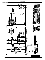
1
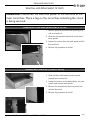
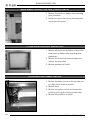
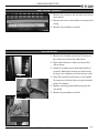
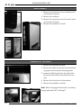
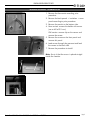
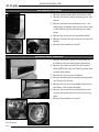
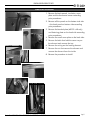
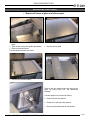
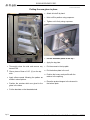
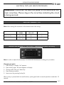
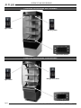
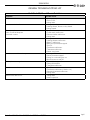
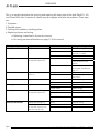
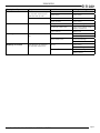
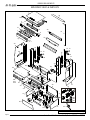
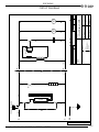
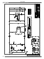
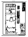
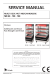
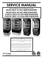
SERVICE MANUAL This Service Manual covers the following US-models: MULTI DECK 25 HOT MERCHANDISER MULTI DECK 40 HOT MERCHANDISER CLASSIC DECK 25 HOT MERCHANDISER CLASSIC DECK 25 COLD MERCHANDISER Model Multi Deck 25 Model Multi Deck 40 Model Classic Deck 25 Hot Model Classic Deck 25 Cold - NOTICE This manual is prepared for the use of trained Service Technicians and should not be used by those not properly qualified. If you have attended a trianing for this product, you may be qualified to perform all the procedures in this manual. This manual is not intended to be all encompassing. If you have not attended a training for this product, you should read, in its entirety, the repair procedure you wish to performto determine if you have the necessary tools, instruments and skills required to perform the procedure. Procedures for which you do not have the necessary tools, instruments and skills should be performed by a trained technician. Reproduction or other use of this Manual, without the express written consent of Fri-Jado, is prohibited. WWW.FRIJADO.COM Service Manual Multi Deck - Classic Deck 25/40 form 9123649 rev. 03/2007 Page 2 Service Manual Multi Deck - Classic Deck 25/40 form 9123649 rev. 03/2007 TABLE OF CONTENTS INDEX Index ............................................................................................................................... 3 General technical data .................................................................................................... 4 Technical Data U.S. Standard Models .................................................................................................4 Removal and replacement of parts .................................................................................. 5 Panels bottom side (Multi Deck 25/40) ...............................................................................................5 Panels bottom side (Classic Deck) ......................................................................................................5 Back panel on bottom side (Classic Deck) ..........................................................................................6 Cover plate on field wiring box ..........................................................................................................6 Illumination/tumble switch.................................................................................................................6 Electronic ballast...............................................................................................................................7 Roller blind.......................................................................................................................................7 Back panels......................................................................................................................................8 Thermostat (Eliwell) ...........................................................................................................................8 Sensor Eliwell thermostat ...................................................................................................................9 Blower air curtain ...........................................................................................................................10 Blower shelf heating .......................................................................................................................10 Heating element .............................................................................................................................11 Safety thermostat (reset) ..................................................................................................................12 Transformer/relay ...........................................................................................................................12 Replacing side glass........................................................................................................................13 Electrical tests and service procedures ........................................................................... 15 Heating element test .......................................................................................................................15 Adjusting Eliwell IC 902/H NTC thermostat (MD/CLD Hot) ................................................................15 Adjusting Eliwell thermostat (continued)............................................................................................16 Adjusting Eliwell thermostat (continued)............................................................................................17 Adjusting Johnson thermostat (CLD Cold) ........................................................................................18 Adjusting Johnson thermostat (continued) ........................................................................................19 Control locations Hot models ..........................................................................................................20 Control locations Cold model ..........................................................................................................20 General troubleshooting list .......................................................................................... 21 Exploded views & Partlists ............................................................................................. 24 Circuit Diagrams ........................................................................................................... 31 Service Manual Multi Deck - Classic Deck 25/40 form 9123649 rev. 03/2007 Page 3 GENERAL TECHNICAL DATA GENERAL TECHNICAL DATA This manual covers the Multi Deck 25 Hot, the Multi Deck 40 Hot and the Classic Deck Hot and Cold series merchandiser cabinets. The cabinets come in two sizes, 25 and 40 inches. • Multi Deck 25 Hot - Merchandiser 25 Inches wide. • Multi Deck 40 Hot - Merchandiser 40 Inches wide. • Classic Deck Hot – Merchandiser 25 Inches wide. • Classic Deck Cold – Merchandiser 25 Inches wide. All of the information, illustrations and specifications contained in this manual are based on the latest product information available at the time of printing. TECHNICAL DATA U.S. STANDARD MODELS Type MD 25 Hot MD 40 Hot Classic Deck Hot Classic Deck Cold 3200 3700 3200 1380 Fuses needed with power connection 208V, 1N~60Hz (1 phase with zero) 1x 20 A 1x 20 A 1x 20 A - Fuses needed with power connection 115V, 1N~60Hz (1 phase with zero) - - - 1x 20 A Power (W) Standard plug from factory NEMA 6-20P G NEMA 6-30P G NEMA 6-20P NEMA 5-20P G G W Net weight 551 lbs 683 lbs 551 lbs 408 lbs Gross weight 716 lbs 858 lbs 716 lbs 574 lbs Height (mm) 75 5/16” 75 5/16” 75 5/16” 75 5/16” Width (mm) 24 3/8” 39 3/8” 24 3/8” 24 7/8” Depth (mm) 37 5/16” 37 5/16” 40 ¾” 37 5/16” Tools • Standard set of tools. • Metric wrenches, sockets and hex socket key wrenches. • VOM with AC current tester (any VOM with a sensitivity of min 20,000 ohms per volt can be used). • Insulation value tester (Megger) • Temperature tester. Page 4 Service Manual Multi Deck - Classic Deck 25/40 form 9123649 rev. 03/2007 REMOVAL AND REPLACEMENT OF PARTS REMOVAL AND REPLACEMENT OF PARTS WARNING: Disconnect the electrical power to the machine at the main circuit box. Place a tag on the circuit box indicating the circuit is being serviced. PANELS BOTTOM SIDE (MULTI DECK 25/40) 1. Remove panel on the front side by lifting it up with a screwdriver. 2. Slide the side panels backwards and remove these panels. 3. Loosen the screws from the back panel and lift this panel out. 4. Reverse the procedure to install. PANELS BOTTOM SIDE (CLASSIC DECK) 1. Slide stainless steel bottom panel towards yourself and remove this. 2. Loosen the screws on the backside for the side panels and remove both panels. 3. Remove the screws from the front panel and remove the panel. 4. Reverse the procedure to install. Service Manual Multi Deck - Classic Deck 25/40 form 9123649 rev. 03/2007 Page 5 REMOVAL AND REPLACEMENT OF PARTS BACK PANEL ON BOTTOM SIDE (CLASSIC DECK) 1. Remove the panels on bottom side according prior procedure. 2. Loosen the screws that secure the back panel and remove this panel. COVER PLATE ON FIELD WIRING BOX 1. Remove all panels on the bottom side and the back panel on bottom side according prior procedures. 2. Remove the screws that secure the box and remove the cover plate. 3. Reverse procedure to install. ILLUMINATION/TUMBLE SWITCH 1. Remove the socket screws on the top side and turn light fixture towards yourself. 2. Replace lamp. 3. Remove wiring from switch and remove the switch by pushing the clamps on both sides. 4. Reverse the procedure to install. Page 6 Service Manual Multi Deck - Classic Deck 25/40 form 9123649 rev. 03/2007 REMOVAL AND REPLACEMENT OF PARTS ELECTRONIC BALLAST 1. Remove the screws on the top side and remove cover panel. 2. Remove the nuts on the ballast and remove the wiring. 3. Reverse the procedure to install. ROLLER BLIND 1. Remove the 2 socket screws and 3 screws on the inside and remove the roller blind. 2. Place roller blind on a table and secure this with a clamp. 3. Loosen the socket screws and slide the blind upwards. Release the tension on the blind by turning it anti clockwise until the tension is low. 4. Place the new blind with the pin in the holder. Put tension on the blind by turning this clockwise for 10 rotations. 5. Replace mounting plate and bearing on the new blind. 6. Reverse the procedure to install. Service Manual Multi Deck - Classic Deck 25/40 form 9123649 rev. 03/2007 Page 7 REMOVAL AND REPLACEMENT OF PARTS BACK PANELS 1. Remove the screws that secure the back panel and remove this panel. 2. Remove the insulation. 3. Remove the screws that secure the cover panel and remove this panel. 4. Reverse the procedure to install. THERMOSTAT (ELIWELL) 1. Remove the honeycomb profile. 2. Remove the socket screws that secure the fastening plate and remove the fastening plate. 3. Loosen the blocking clips on the sides of the thermostat and remove thermostat from housing. 4. Remove the wiring from the thermostat. 5. Reverse the procedure to install. Note: When changing the thermostat, first always change parameter HC to heating H. Page 8 Service Manual Multi Deck - Classic Deck 25/40 form 9123649 rev. 03/2007 REMOVAL AND REPLACEMENT OF PARTS SENSOR ELIWELL THERMOSTAT 1. Remove the thermostat according prior procedure. 2. Remove the back panels + insulation + cover panel according to prior procedure. 3. Remove the panels on the bottom side. 4. New version: remove the holder with sensor (use a drill of 3.2 mm) Old version: remove clip on the sensor and remove the sensor. 5. Remove the screws on the front panel and remove this panel. 6. Lead sensor through the grommet and lead the sensor to the back side. 7. Reverse the procedure to install. Note: See to it that the sensor is placed straight inside the chamber. Service Manual Multi Deck - Classic Deck 25/40 form 9123649 rev. 03/2007 Page 9 REMOVAL AND REPLACEMENT OF PARTS BLOWER AIR CURTAIN 1. Remove honeycomb profile and bottom shelf. 2. Remove the electric panel according prior procedure. 3. Remove all panels on the bottom side + the back panel on bottom side and the cover plate on the field wiring box according prior procedures. 4. Remove the wiring on the connection block. 5. Remove the bolts on the inside and remove the blower. 6. Reverse the procedure to install. BLOWER SHELF HEATING 1. Remove the electric panel and all panels on the bottom side according prior procedures. 2. Remove the socket screws from the bended plate (MD25/40 only) and fastening plate and remove these plates. 3. Remove the wiring from the blower. 4. Remove the bolts on the round mounting plate and remove the blower. 5. Remove the nut on the fan blade and remove fan blade. (Left handed threads). 6. Remove the screws that hold the blower and remove the blower from the round mounting plate. 7. Reverse the procedure to install. Turning direction anti-clockwise Page 10 Service Manual Multi Deck - Classic Deck 25/40 form 9123649 rev. 03/2007 REMOVAL AND REPLACEMENT OF PARTS HEATING ELEMENT 1. Remove the back panels, insulation, cover plate and the thermostat sensor according prior procedures. 2. Remove all the panels on the bottom side side + the back panel on bottom side according prior procedures. 3. Remove the bended plate (MD 25+40 only) and fastening plate on the back side according prior procedures. 4. Remove the small cover plate on the back side. 5. Remove the bolts that hold the cover tray on the element and remove the tray. 6. Remove the wiring on the heating element. 7. Remove the nut that secures the element and remove the element from the inside. 8. Reverse the procedure to install. Service Manual Multi Deck - Classic Deck 25/40 form 9123649 rev. 03/2007 Page 11 REMOVAL AND REPLACEMENT OF PARTS SAFETY THERMOSTAT (RESET) 1. Remove the electric panel, back panels, insulation and cover plate, and the cover plate on the field wiring box according prior procedures. 2. Remove the clip on the sensor and remove the sensor. 3. Remove the wiring on the thermostat. 4. Remove the screws that secure the thermostat and remove the thermostat. 5. Reverse procedure to install. Note: a. Each hot air column has a built in thermostat. b. Set the thermostat on 175°C. Reset button TRANSFORMER/RELAY 1. Remove all panels on the bottom side, the back panel on bottom side and the cover plate on the field wiring box according prior procedures. 2. Remove the wiring from the transformer or relay. 3. Remove the screws that secure the transformer / relay and remove the transformer / relay. 4. Reverse procedure to install. Page 12 Service Manual Multi Deck - Classic Deck 25/40 form 9123649 rev. 03/2007 REMOVAL AND REPLACEMENT OF PARTS Replacing a side glass in the MD REPLACING SIDE GLASS Remove all traces of glass and silicone past. Remove the product stopper from the bottom plate. Take out the honeycomb profile and retainer. Remove the bottom plate. The attachment brackets are visible. Remove the six screws from the top plate. Remove the insulation plates. The attachment brackets are visible. Remove the top plate. Remove the old notches that were glued to the glass by taking them from the attachment brackets. Use two spanners to proceed as follows: Hold nut B with one spanner. Detach nut A with the other spanner. Remove the brackets and the old notches. Service Manual Multi Deck - Classic Deck 25/40 form 9123649 rev. 03/2007 Page 13 REMOVAL AND REPLACEMENT OF PARTS Putting the new glass in place Attach all nuts B by hand. X Hold nut B in position using a spanner. Tighten nut A firmly using a spanner. Put the insulation plates in the top ! Apply the top plate. Thoroughly clean the side and remove any traces of fat. Glue a piece of foam of 1/8". (X) on the top side. Apply silicone paste following the pattern as shown in above picture. Position the notches which are glued to the glass in the holes. Put the screws in the top plate Put the bottom plate in the unit. Position the honey comb profile with the retainer in the opening. Place the product stopper in the channel in the bottom plate. Put the brackets on the threaded studs. Page 14 Service Manual Multi Deck - Classic Deck 25/40 form 9123649 rev. 03/2007 ELECTRICAL TESTS AND SERVICE PROCEDURES ELECTRICAL TESTS AND SERVICE PROCEDURES WARNING: Disconnect the electrical power to the machine at the main circuit box. Place a tag on the circuit box indicating the circuit is being serviced. HEATING ELEMENT TEST Note: When testing the resistance of the element remove the wiring. Type Wattage/ Voltage Resistance Ω -10% + 0% Current A MD 25 Hot + Classic Deck Hot 1500 / 208 1500 / 230 28,8 35,3 7.2 6.5 MD 40 Hot 1750 / 208 1750 / 230 24,7 30,2 8.4 7.6 ADJUSTING ELIWELL IC 902/H NTC THERMOSTAT (MD/CLD HOT) Note: In order to adjust the thermostat, first remove the thermostat according prior procedure. Changing set point 1. Press set key. In display “set” appears. 2. Press set key again. Set point appears in display. 3. Change value with up or down key. 4. Press set key to confirm. 5. Leave menu by pressing fnc key 2x. When no key is pressed after last confirmation, system goes back to normal operation mode after 15 seconds. Service Manual Multi Deck - Classic Deck 25/40 form 9123649 rev. 03/2007 Page 15 ELECTRICAL TESTS AND SERVICE PROCEDURES ADJUSTING ELIWELL THERMOSTAT (CONTINUED) Programming menu The programming menu consists of 4 folders: CP – diS – CnF – Fpr. Each folder contains level 1 parameters. To enter these folders proceed as following: 1. Press set key for 5 seconds. In display “CP” appears. 2. Press up or down key to scroll through the folders. 3. To enter the folder press set key. In display the first parameter appears. Setting internal parameters 1. Press set key for 5 seconds. In display “CP” appears. 2. Press up or down key to go to the desired folder. 3. Press set key. In display the first parameter of this folder appears. 4. Press set key to read out value. 5. Change value with up or down key. 6. Press set key to confirm. 7. Press up key for next parameter and follow instructions 4 to 6. 8. Press fnc key to return to the folder menu and follow instructions 2 to 6. 9. Leave menu by pressing fnc key 2x. When no key is pressed after last confirmation, system goes back to normal operation mode after 15 seconds. Replacing of thermostat When you install a new thermostat, then always change parameter HC first to H. Otherwise some other parameters cannot be changed to the desired value. Error message on display E1: Temperature sensor broken or wiring problem sensor. Page 16 Service Manual Multi Deck - Classic Deck 25/40 form 9123649 rev. 03/2007 ELECTRICAL TESTS AND SERVICE PROCEDURES ADJUSTING ELIWELL THERMOSTAT (CONTINUED) Fpr cnF diS CP Setpoint °F Standard value from suplier Multi Deck 40 Hot Multi Deck 25 Hot + Classic Deck Hot Description Parameter Folder Parameters Eliwell thermostat 176 176 0 1 1 0 Maximum setpoint °F 185 185 LSE Minimum setpoint °F 149 149 HC Function: Heating/Cooling H/C H H C Ont Regulator activation time 0 0 0 OFt Regulator disabled state time 0 0 0 dOn Delay time regulator relay 0 0 0 dOF Delay after switch-off 0 0 0 dbi Delay between switch-ons 0 0 0 OdO Delay time outputs 0 0 0 diF Switching differential °F HSE LOC Keyboard locking n n n PA1 Password 1 0 0 0 ndt Number display type - - CA1 Calibration 1 0 0 0 dro Function: °C/°F 0-1 1 1 0 H00 Probe type 0=PTC 1=NTC 1 1 0 rEL Device version (read only) - - tAb Reserved (read only) - - UL Upload - - dL Download - - Service Manual Multi Deck - Classic Deck 25/40 form 9123649 rev. 03/2007 Page 17 ELECTRICAL TESTS AND SERVICE PROCEDURES ADJUSTING JOHNSON THERMOSTAT (CLD COLD) Note: In order to adjust the thermostat, first remove the thermostat according prior procedure. Changing set point 1. Press enter key for 2 seconds. In display the setpoit appears (32°F). 2. Change value with up or down key. 3. Press enter key to confirm. Setting internal parameters 1. Press enter key for 7 seconds. In display the first parameter appears (HY). 2. Press enter key to read out value. 3. Change value with up or down key. 4. Press enter key to confirm. 5. The next parameter appears. Follow instructions 2 to 4. When no key is pressed after last confirmation, system goes back to normal operation mode after 15 seconds. Replacing of thermostat When you install a new thermostat, then always change parameter Un first to 1 (°F). Otherwise some other parameters cannot be changed to the desired value. You can run through the parameters with the up or down keys, once you are inside the parameter settings. Options 1. Self-test procedure. To execute this you first have to diconnect loads before self-test procedure. Press the up and down keys together, and hold for 5 seconds. Note: To return to normal mode the control must be switched OFF and ON again. 2. Manual start of defrost cycle. Hold the defrost key for 3 seconds. Note: The temperature has to be lower then the setting of parameter dt (40°F). 3. Actual temperature of sensor 1 (Thermostat ). Press up key shortly 2 times. 4. Actual temperature of sensor 2 (Evaporator). Press down key shortly 2 times. Page 18 Service Manual Multi Deck - Classic Deck 25/40 form 9123649 rev. 03/2007 ELECTRICAL TESTS AND SERVICE PROCEDURES ADJUSTING JOHNSON THERMOSTAT (CONTINUED) Error messages on display F1: Interuption or short circuit of thermostat sensor. F2: Interuption or short circuit of evaporator sensor. EE: Programme failure. Standard value from supplier 0 °F 4 2 °F -40 0 °F 99 30 Anti short cycling min 5 2 co Deep freezing time min 60 60 Ah High temperature alarm °F 50 10 AL Low temperature alarm °F -50 -10 Ad Alarm differential K 1 1 At Alarm time delay min 0 30 Description 32 Parameter Classic Deck Cold Parameters Johnson thermostat Setpoint °F HY Hysteresis LL Lower sepoint limit hL Higher setpoint limit cc dF Defrost function 0 0 dE Defrost end function 1 1 dt Defrost termination temp. °F 40 7 di Defrost interval time hrs 3 6 dd Max defrost duration min 40 40 dc Dripping time min 0 5 du First defrost after power on min off 10 dP Display during defrost 0 0 dr Delayed displayed temp. after defrost 10 20 iF Digital input function 0 0 5 5 1 0 min 0 5 id Digital input time delay FF Fan operating function min Fd Fan start up delay after defrost end Fr Fan start temp. after defrost end °F -5 -5 SF Thermostat operating function in case of sensor failure 2 2 So Offset temp. sensor -12 0 Un Temperature units °C/°F 0/1 1 0 Pu Display updating time delay sec 1 1 K Service Manual Multi Deck - Classic Deck 25/40 form 9123649 rev. 03/2007 Page 19 ELECTRICAL TESTS AND SERVICE PROCEDURES CONTROL LOCATIONS HOT MODELS Light switch Heating switch Thermostat (Eliwell) CONTROL LOCATIONS COLD MODEL * Light switch Refrigeration switch Thermostat (Johnson) Page 20 Service Manual Multi Deck - Classic Deck 25/40 form 9123649 rev. 03/2007 TROUBLESHOOTING GENERAL TROUBLESHOOTING LIST Multi Deck 25/40 and Classic Deck Hot Symptom Possible causes No power to cabinet controls. 1. Main breaker open. 2. Fuses F1-2-3. 3. Wiring loose. Main fuse or breaker blows. 1. Wiring incorrectly. 2. Heating element, blower or relay shorted. 3. Wiring shorted. Illumination does not work. Note: On MD 40 lamps are connected in series. 1. Lamp malfunction. 2. Tumble switch malfunction. 3. Electronic ballast malfunction. 4. Wiring loose. No heating. 1. Wiring loose. 2. Heating elements malfunction. 3. Relay K1 malfunction. 4. Both security thermostats tripped. 5. Fuse F3. 6. Transformer malfunction. 7. Thermostat malfunction. 8. Sensor wiring loose. Unit does not reach desired temperature. 1. Heating element malfunction 2. Security thermostat tripped. 3. Strong air current along the unit. 4. Burned contact on relay K1. Security thermostat tripped. 1. Blower for heating malfunction. 2. Setting of thermostat. 3. Thermostat malfunction. No indication on electronic thermostat. 1. Fuse F3. 2. Transformer malfunction.(if fixed in unit) 3. Electronic thermostat malfunction. 4. Wiring loose. Blower motor does not run. 1. Wiring loose. 2. Motor inoperative. Service Manual Multi Deck - Classic Deck 25/40 form 9123649 rev. 03/2007 Page 21 TROUBLESHOOTING This is an analytic description for servicing and repairing all major parts of the Multi Deck 25 - 40 and Classic Deck Hot. It consists of 4 basic steps to recognize and solve the problems. These steps are: 1. Symptoms. 2. Possible causes. 3. Solving of the problem: checking/action. 4. Replacing of parts and testing. a. Replacing is described in this service manual. b. For testing see control locations on page 17 of this manual. Description of part Symptoms Possible causes Solving: checking / action Relay K1 Relay does not come in. Wiring Check the wiring Coil malfunction Check resistance of coil. This should be ± 6.4MΩ Contact burned Check the contacts Wiring Check the wiring Heating element Tumble switch Electronic ballast PL lamp(s) Security thermostat Electronic thermostat Page 22 The cabinet is not reaching the adjusted temperature Check the power on the element Element malfunction Check the current with AC current tester. See table on page 15 Light or heating does not switch on Wiring Check the wiring Contact burned Check the voltage on “in”and “output”. Light does not switch on Wiring Check the wiring Ballast malfunction Replace ballast Wiring Check the wiring Lamp(s) broken Replace lamp(s) Wiring Check the wiring Security thermostat switched off Reset thermostat Security thermostat malfunction Replace thermostat Display does not light up Wiring Check the wiring The cabinet is not reaching the adjusted temperature or does not heat up at all Loose sensor Check sensor Thermostat malfunction Replace thermostat Light does not switch on The cabinet is not reaching the adjusted temperature Service Manual Multi Deck - Classic Deck 25/40 form 9123649 rev. 03/2007 TROUBLESHOOTING Description of part Symptoms Possible causes Solving: checking / action PTC 1000 sensor The cabinet is not reaching the adjusted temperature or does not heat up at all Broken sensor Replace sensor Loose sensor Check wiring The cabinet becomes too hot Broken sensor Replace sensor Sensor shorted Check wiring Wiring Check the wiring Transformer malfunction Check output voltage (12V) / Replace transformer Fuse F3 blown Replace fuse Wiring Check wiring Transformer Blower(s) on heaters The cabinet does not heat up Security thermostat switched off Check voltage on blower Blower malfunction Check for blockage Replace blower Blower(s) air curtain The cabinet is not reaching the adjusted temperature Wiring Check wiring Check the voltage on blower Blower malfunction Check for blockage Replace blower Service Manual Multi Deck - Classic Deck 25/40 form 9123649 rev. 03/2007 Page 23 EXPLODED VIEWS AND PARTLISTS EXPLODED VIEWS & PARTLISTS 33 35 10 5 31 3 30 32 9 7 8 7 11 11-1 40 70 6 3 8 1 36 2 37 12 15 13 59 15 13 12 38 14 38 39 60 39 17 34 16 16 17 22 66 63 63-1 63-2 24 20 62 61 43 42 49 46 25 45 44 81-1 19 18 64 65 50 41 48 27 81 82 28 52 51 13 47 80 80-1 80-1 80-2 23 Multi Deck 25/40 Hot Assembly Drawing Page 24 Service Manual Multi Deck - Classic Deck 25/40 form 9123649 rev. 03/2007 EXPLODED VIEWS AND PARTLISTS ITEM PART NO MODEL QTY Description 1 9222012 MD25 1 Protection plate dia, transparent 1 9222033 MD40 1 Protection plate dia, transparent 2 9222011 MD25 1 Protection plate, illumination inside 2 9222032 MD40 1 Protection plate, illumination inside 3 9181008 All models 2 Switch, tumble 5 9181071 All models 1 Sticker, light 6 9181072 All models 1 Sticker, heat 7 9082897 MD25 1 Lamp holder 7 9082897 MD40 2 Lamp holder 8 9160019 MD25 1 Lamp, PLL 55 W 8 9221006 MD40 2 Lamp, PLL 36 W 9 9222036 MD25 1 Night roller-blind 9 9222037 MD40 1 Night roller-blind 10 9222065 MD25 1 Ballast, 1x 55 W 10 9222064 MD40 1 Ballast, 1x 55 W 11 9222013 MD25 1 Protection plate, dia, opal 11 9222034 MD40 1 Protection plate, dia, opal 11-1 9223010 MD25 1 Diastrip 11-1 9223012 MD40 1 Diastrip 12 9222055 MD25 2 Heating element 208 V, 1500 W 12 9222056 MD40 2 Heating element 208 V, 1750 W 13 3500037 All models 2 Thermostat with reset, 100-320 °C 14 9221020 All models 1 Temperature sensor 15 9073181 All models 2 Cable clamp 16 9221017 All models 2 Blower 17 9221001 MD25 1 Blower 17 9221001 MD40 2 Blower 18 8033659 All models 1 Connecting block, 9-pol. 19 9181022 All models 1 Relay 20 9221016 All models 1 Thermostat, Eliwell 21 9222066 All models 1 Thermometer 100-200 °F 22 8031364 MD25 1 Grid, blower 22 8031364 MD40 2 Grid, blower 23 9172401 MD25 1 Connecting cable with plug 15-20P 23 9172409 MD40 1 Connecting cable with plug 6-30P 24 9222015 All models 1 Protection plate, thermostat 25 9224089 All models 1 Bracket, thermostat 27 9181036 All models 1 Transformer 12V 28 9044564 All models 1 Connecting block, 1,2,3 30 9225086 MD25 1 Light box 30 9224586 MD40 1 Light box 31 9224067 MD25 1 Bracket, lampholder 31 9224067 MD40 2 Bracket, lampholder 32 9225089 MD25 1 Bracket, lamp 32 9224068 MD40 1 Bracket, lamp 33 9225087 MD25 1 Top plate 33 9224587 MD40 1 Top plate 34 9224121 All models 1 Sensor holder Service Manual Multi Deck - Classic Deck 25/40 form 9123649 rev. 03/2007 Page 25 EXPLODED VIEWS AND PARTLISTS ITEM PART NO MODEL QTY Description 35 9225070 MD25 1 Top plate, bended 35 9224570 MD40 1 Top plate, bended 36 9225076 MD25 1 Panel 36 9224577 MD40 1 Panel 37 9225071 MD25 1 Bottom plate, bended 37 9224571 MD40 1 Bottom plate, bended 38 9224097 All models 2 Bracket, temperature probe 39 9222048 All models 8 Rubber gasket 40 9220048 All models 1 Glass panel, left, ass. 41 9220049 All models 1 Glass panel, right, ass. 42 9225029 MD25 1 Front plate bottom 42 9224529 MD40 1 Front plate bottom 43 9223053 MD25 1 Bumper 43 9223064 MD40 1 Bumper 44 9171014 All models 2 Plug 45 9223054 All models 3 Spacer 46 9225025 MD25 1 Front panel underframe 46 9224525 MD40 1 Front panel underframe 47 9224028 All models 1 Right side panel underframe 48 9225026 MD25 1 Rear panel underframe 48 9224526 MD40 1 Rear panel underframe 49 9224027 All models 1 Left side panel underframe 50 9172066 All models 2 Castor with brake 51 9172125 All models 2 Castor without brake 52 9224092 All models 2 Protection plate electricity 59 9224005 All models 6 Shelf support 60 9220011 MD25 3 Shelf 60 9220015 MD40 3 Shelf 61 9220010 MD25 1 Bottom shelf 61 9220016 MD40 1 Bottom shelf 62 9221008 All models 9 Spacing pin, 3D nut M6 63 9226023 MD25 3 Holder, price rail 63 9227023 MD40 3 Holder, price rail 63-1 9223024 MD25 3 Price rail, transparent 63-1 9223025 MD40 3 Price rail, transparent 63-2 9223014 MD25 3 Dia strip, price rail 63-2 9223016 MD40 3 Dia strip, price rail 64 9222010 MD25 1 Productstopper , bottom, perspex 64 9222030 MD40 1 Productstopper , bottom, perspex 65 9222044 MD25 1 Air divider, honeycomb 65 9222045 MD40 1 Air divider, honeycomb 66 9225090 MD25 1 Bracket, honeycomb 66 9224589 MD40 1 Bracket, honeycomb 70 9225077 MD25 1 Rear plate 70 9224578 MD40 1 Rear plate 80 9044205 All models 3 Fuse Holder 80-1 9110250 All models 2 Fuse SC10, 10A 80-2 9181049 All models 1 Fuse SC2.5, 2.5A Page 26 Service Manual Multi Deck - Classic Deck 25/40 form 9123649 rev. 03/2007 EXPLODED VIEWS AND PARTLISTS ITEM PART NO MODEL QTY Description 81 9224101 All models 1 Connection box 81-1 9224102 All models 1 Cover, box 82 9070840 All models 1 Grommet Service Manual Multi Deck - Classic Deck 25/40 form 9123649 rev. 03/2007 Page 27 EXPLODED VIEWS AND PARTLISTS 33 5 30 3 35 10 31 7 6 9 1 40 11 32 2 11-1 8 70 3 36 12 15 59 13 15 12 13 38 38 14 39 16 34 39 60 16 41 22 17 24 63 63-1 63-2 20 62 61 45 42 65 19 25 66 18 64 48 43 81-1 81 82 44 47 47 53 13 80-1 80 52 27 47 50 80-1 80-2 28 46 54 51 53 23 Classic Deck Hot Assembly Drawing Page 28 Service Manual Multi Deck - Classic Deck 25/40 form 9123649 rev. 03/2007 EXPLODED VIEWS AND PARTLISTS ITEM PART NO QTY Description 1 9222109 1 Protection plate dia, transparent 2 9222011 1 Protection plate, illumination inside 3 9181008 2 Switch, tumble 5 9181071 1 Sticker, light 6 9181072 1 Sticker, heat 7 9082897 1 Lamp holder 8 9160019 1 Lamp, PLL 55 W 9 9222036 1 Night roller-blind 10 9222065 1 Ballast, 1x 55 W 11 9222110 1 Protection plate, dia, opal 11-1 9223011 1 Diastrip 12 9222055 2 Heating element 208 V, 1500 W 13 3500037 2 Thermostat with reset, 100-320 °C 14 9221020 1 Temperature sensor 15 9073181 2 Cable clamp 16 9221017 2 Blower 17 9221001 1 Blower 18 8033659 1 Connecting block, 9-pol. 19 9181022 1 Relay 20 9221016 1 Thermostat, Eliwell 21 9222066 1 Thermometer 100-200 °F 22 8031364 1 Grid, blower 23 9172401 1 Connecting cable with plug 15-20P 24 9222015 1 Protection plate, thermostat 25 9224089 1 Bracket, thermostat 27 9181036 1 Transformer 12V 28 9044564 1 Connecting block, 1,2,3 30 9226030 1 Light box 31 9224067 1 Bracket, lampholder 32 9225089 1 Bracket, lamp 33 9225087 1 Top plate 34 9224121 1 Sensor holder 35 9225070 1 Top plate, bended 36 9225076 1 Panel 38 9224097 2 Bracket, temperature probe 39 9222048 8 Rubber gasket 40 9220044 1 Glass panel, left, ass. 41 9220045 1 Glass panel, right, ass. 42 9226029 1 Front plate bottom 43 9223053 1 Bumper 44 9171014 2 Plug 45 9223054 3 Spacer 46 9226027 1 Front panel underframe 47 9226024 2 Side panel underframe 48 9226026 1 Rear panel underframe 50 9172066 2 Castor with brake 51 9172125 2 Castor without brake 52 9224092 2 Protection plate electricity Service Manual Multi Deck - Classic Deck 25/40 form 9123649 rev. 03/2007 Page 29 EXPLODED VIEWS AND PARTLISTS ITEM PART NO QTY Description 53 9226025 2 Plinth 54 9226028 1 Plinth 59 9224005 6 Shelf support 60 9220011 3 Shelf 61 9220010 1 Bottom shelf 62 9221008 9 Spacing pin, 3D nut M6 63 9226023 3 Holder, price rail 63-1 9223024 3 Price rail, transparent 63-2 9223014 3 Dia strip, price rail 64 9222010 1 Productstopper , bottom, perspex 65 9222044 1 Air divider, honeycomb 66 9225090 1 Bracket, honeycomb 70 9225077 1 Rear plate 80 9044205 3 Fuse Holder 80-1 9110250 2 Fuse SC10, 10A 80-2 9181049 1 Fuse SC2.5, 2.5A 81 9224101 1 Connection box 81-1 9224102 1 Cover, box 82 9070840 1 Grommet Page 30 Service Manual Multi Deck - Classic Deck 25/40 form 9123649 rev. 03/2007 Service Manual Multi Deck - Classic Deck 25/40 form 9123649 rev. 03/2007 � � � �� �� �� �� �� �� �� ��� �� �� ���� �� �� ����� �������������������� � � �� � ���������������� ���������������������������������� ����� ������������� �������� ����������� � � �� � ���� �� ������������� ����������������������������� ������������������������������� ��������������������� ���������������� ���������������������� �������� � �� ���������� �������� ����� �������� �� ��������������� ������� ���������� �� �� �� �������� � �� ������� ��� ���������� �� �� ������� �� ���������� ������� �� ������������� ������ ��� �������� ������� ��������� ����������� ��������� ����� ������������� �� �� �� �������������������� ��������� �������� � � CIRCUIT DIAGRAMS CIRCUIT DIAGRAMS MD15 Hot Circuit Diagram Page 31 ������� �������� CIRCUIT DIAGRAMS MD25/Classic Deck Hot Circuit Diagram Page 32 Service Manual Multi Deck - Classic Deck 25/40 form 9123649 rev. 03/2007 CIRCUIT DIAGRAMS MD40 Hot Circuit Diagram Service Manual Multi Deck - Classic Deck 25/40 form 9123649 rev. 03/2007 Page 33 CIRCUIT DIAGRAMS CLD Cold Circuit Diagram Page 34 Service Manual Multi Deck - Classic Deck 25/40 form 9123649 rev. 03/2007 Service Manual Multi Deck - Classic Deck 25/40 form 9123649 rev. 03/2007 Page 35 Fri-Jado Inc. • 180 Kehou Blvd. • Carol Stream, Ill. 60188 • USA • Tel. 630-784-3469 • Fax. 630-784-1650 • toll free 877-FRI-JADO • [email protected] • www.frijado.com Page 36 Service Manual Multi Deck - Classic Deck 25/40 form 9123649 rev. 03/2007