1
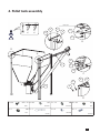
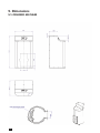
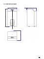
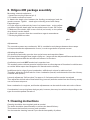
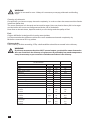
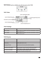
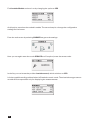
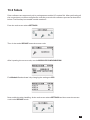
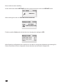
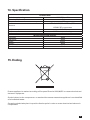
INSTRUCTION MANUAL
& SERVICE MANUAL
ORLIGNO 400
Content
1. Delivery . . . . . . . . . . . . . . . . . . . . . . . . . . . . . . . . . . . . . . . . . . . . . . . . . . . . . . . . . . . . . . . . . . . . . . . . 3
2. Installation and assembly . . . . . . . . . . . . . . . . . . . . . . . . . . . . . . . . . . . . . . . . . . . . . . . . . . . . . . . . . 3
3. Boiler view after assembly . . . . . . . . . . . . . . . . . . . . . . . . . . . . . . . . . . . . . . . . . . . . . . . . . . . . . . . . 6
4. Pellet tank assembly . . . . . . . . . . . . . . . . . . . . . . . . . . . . . . . . . . . . . . . . . . . . . . . . . . . . . . . . . . . . . 7
5. Dimensions . . . . . . . . . . . . . . . . . . . . . . . . . . . . . . . . . . . . . . . . . . . . . . . . . . . . . . . . . . . . . . . . . . . . . 8
5.2. ORLIGNO 400 16kW . . . . . . . . . . . . . . . . . . . . . . . . . . . . . . . . . . . . . . . . . . . . . . . . . . . 8
5.3. ORLIGNO 400 30kW . . . . . . . . . . . . . . . . . . . . . . . . . . . . . . . . . . . . . . . . . . . . . . . . . . . 9
6. Dimensions . . . . . . . . . . . . . . . . . . . . . . . . . . . . . . . . . . . . . . . . . . . . . . . . . . . . . . . . . . . . . . . . . . . . 10
7. Cleaning instructions . . . . . . . . . . . . . . . . . . . . . . . . . . . . . . . . . . . . . . . . . . . . . . . . . . . . . . . . . . . 10
2
Thank You for choosing a ORLIGNO 400 pellet burner from Eko-Vimar Orlanski.
We ask you review this operating and installation manual before you start installing your new
ORLIGNO 400 pellet boiler in order to avoid harm to people and product.
We recommend that the boiler is installed by a licensed plumber.
arning!
W
That you MUST unplug the connector before the burner is removed from the boiler.
arning!
W
The feeding hose and electric ignition are wearing parts and are therefore not covered
by any warranty.
This manual contains information that is protected under copyright law.
1. Delivery
Orligno 400 package is packed on one pallet wrapped up with foil. External elements of Orligno 400
are package pached in cardbox:
- pellet tank
- elastic pipe with clamp
- metal connector
- auqer with motoreducer is wrapped in foil attached to pallet.
2. Installation and assembly
Generally, placement and installation must be carried out by competent skilled installers, and it is
installer´s responsibility that he has the necessary training and certification to conduct mounting.
All applicable standards and regulations are to be followed at the placement and installation,
including:
- National Working Environment Authority Regulations (WEA)
- Water Norm
- Building Code, including distance to combustible material
- Fire Instructions.
3
Orligno 400 placement in boiler room.
Air Draft Stabilizer:
When installing a ORLIGNO 400, we strongly recommend that you mount an air draft stabilizer,
either at the flue between the boiler and the chimney, or directly on the chimney.
If there are an excessive chimney draft, there is an increased risk for high consumption of wood
pellets.
We prescribe that you operate with as low draft as possible, usually not more than 10 Pa, it gives
the controller optimal conditions.
4
Warning!
It is required to install protection from low temperature water return to boiler.
Return water should never drop below 55°C.
Check if fumes sensor is fitted tightly
Connectors from snail assembled with
connectors from the controller
Unplug the burner before
opening the burner.
For cleaning the hearth pull the stick back
and forth while the boiler is working.
Termix sensor fuse must be
replaced if it does not work.
Hearth has to be cleaned approx.
once a week
Approx. every third week, top cover over the flue pipe must be removed and flues should
be cleaned with cleaning tools.
5
3. Boiler view after assembly
1. Boiler feeder
2. Motoreducer
3. Elastic feeding pipe
4. Metal connector
5. Boiler controler
6. Pellet tank 450l
7. Burners handles
8. burner
9. Burner cleaning handle
6
4. Pellet tank assembly
8
13
Bolt M8
B
x1
x1
G
D
x1
A
C
E
x3
B
D
A
A
D
F
B
A
C
B
C
B
D
C
H
A
D
A x 46
M5 x 12 B x 46
Bolt
Ex4
M5 C x 14
Washer
M8 F x 1
Nut
M8 D x 46
Washer
Gx2
Chain
M5
Nut
Hx1
Handle
Gasket
7
5. Dimensions
5.1. OrLignO 400 16kW
8
5.2. OrLignO 400 30kW
604,4
619,1
662,4
1227,2
43,3
9
6. Orligno 400 package assembly
Mounting external equipment:
1. Attach burner plug to burner (pic 1)
2. Fit metal connector to burner
3. Attach the elastic pipe between the feeding screw(auger) and the
metal connector. Tighten elastic pipe to feeding screw with clamp.
External auger:
4. Fit the auger to pellet tank by insert it to bottom base so the pellets
can fall through the elastic pipe into the pellet burner in max. 50° incline.
5. Make sure the elastic pipe is near vertical (no bends), so the pellets
drop directly into the hearth.
6. Attach the connector from the controller to auger's motoreducer.
7. Fit the plug 230V to socket.
pic. 1
Adjustments:
The controler system runs continuosly 100 % modulation and changes between these steps.
It is important that the adjustment is correct, in order to get boiler to operate correct.
Adjusting the pellets:
You should occasionally open the door to the burner and watch the flame.
Ech time the fuel changed (dust, length of pille, etc...) auger will also dispense different and therefore
it will also dispense different and have an influence on the burn.
A pellet burner should nOT smoke but it must be close.
The smoke from the chimney must be invisible down to a few degrees of frost then it could be seen
as a white White wapor that disappears 3-6 feet above the chimney.
Invisible smoke is a sign of good combustion, sufficient air volume in relation to fuel.
Therefore, adjust the air/fuel ratio for richer combustion (less air) until the smoke from the chimney
could Be seen (brown).
Let each adjustment “fall into place” for approx. 2-3 minutes until the smoke is analyzed
Then adjust the air/fuel ratio to less fat burning (more air) until the smoke from the chimney exactly
can not be seen anymore.
Now combustion is rough set, and further adjustments can be made from the ash color or flame.
If combustion is correct it gives a dark gray ash, however, there may be variations depending on the
type of wood the pellets is made of.
7. Cleaning instructions
Cleaning should be done regularly and as needed.
The boiler should be cleaned weekly to achieve the best efficiency.
This ensures the best fuel economy and operation.
You increase the cleaning interval if you use the best quality of pellets.
10
Warning!
If boiler is not used for over 14 days it is necessary to empty pellet tank and feeding
auger.
Cleaning mechanism assembly in Orligno 400 - option.
11
Warning!
If boiler is not used for over 14 days it is necessary to empty pellet tank and feeding
auger.
Cleaning of pellet tank:
Occasionally you have to empty the tank completely, in order to clean the area around the feeder
inlet ffrom pellet dust
The more dust there is in the tank and around the auger inlet, may lead to fewer pills in the auger
and the boiler will come out of alignment with the risk of downtime.
How often to do tank clean, depends entirely on silo design and the quality of fuel.
Fuel:
Orligno 400 boiler is designed for burning wood pellets.
It is important that the pellets are without to much sawdust and stored completely dry
Moisture content max. 8% op pellets.
Chimney draft:
If the chimney draft is exceeding 15 Pa, a draft stabilizer should be mounted in the chimney.
arning!
W
By chimney temperatue less than 180°C at rated output, you should be aware that smoke
dose not condense in the chimney as it gives soot. At particularly low smoke temperature
it may be necessary to put a ceramic or stainless steel sleeve in the chimney.
Technical data
Type
Weight
Flue
Water outlet, return
Efficiency
Power range
boiler class EN 303-5
Required draft
Max working pressure
Water content
Max boiler temp.
Min boiler temp.
Flue gas temp.
nominal
minimal
Flue gas flow
nominal
minimal
Fuel usage
nominal
minimal
12
unit
kg
mm
inch
%
kW
16kW
142,5
133
1
89,4
3,9-16
3
10
2,5
49
80
60
30kW
190
155
1
91,8
7,8-30
3
10
2,5
57
80
60
°C
146
77
173
84
kg/h
33
13
60,1
19,6
kg/h
3,5
0,9
6,7
1,75
Pa
Bar
l
°C
°C
Controller's manual
Contents
8. Connection - electric scheme . . . . . . . . . . . . . . . . . . . . . . . . . . . . . . . . . . . . . . . . . . . . . . . . . . . . 15
9. Overview of the basic functions . . . . . . . . . . . . . . . . . . . . . . . . . . . . . . . . . . . . . . . . . . . . . . . . . . 17
9.1. Control panel . . . . . . . . . . . . . . . . . . . . . . . . . . . . . . . . . . . . . . . . . . . . . . . . . . . . . . . . 17
9.1.1 The status LED . . . . . . . . . . . . . . . . . . . . . . . . . . . . . . . . . . . . . . . . . . . . . . . . . . 17
9.1.2 Buttons . . . . . . . . . . . . . . . . . . . . . . . . . . . . . . . . . . . . . . . . . . . . . . . . . . . . . . . . 18
9.1.3 Graphic display . . . . . . . . . . . . . . . . . . . . . . . . . . . . . . . . . . . . . . . . . . . . . . . . . 19
9.2. Statuses of furnace . . . . . . . . . . . . . . . . . . . . . . . . . . . . . . . . . . . . . . . . . . . . . . . . . . . 19
10. Handling . . . . . . . . . . . . . . . . . . . . . . . . . . . . . . . . . . . . . . . . . . . . . . . . . . . . . . . . . . . . . . . . . . . . . . 20
10.1. Navigation in the menu . . . . . . . . . . . . . . . . . . . . . . . . . . . . . . . . . . . . . . . . . . . . . . . 20
10.2. Starting regulator - ON . . . . . . . . . . . . . . . . . . . . . . . . . . . . . . . . . . . . . . . . . . . . . . . . 20
10.3. Switching off the regulator - OFF . . . . . . . . . . . . . . . . . . . . . . . . . . . . . . . . . . . . . . . 20
10.4. Time scheduling . . . . . . . . . . . . . . . . . . . . . . . . . . . . . . . . . . . . . . . . . . . . . . . . . . . . . 21
10.5. Service password . . . . . . . . . . . . . . . . . . . . . . . . . . . . . . . . . . . . . . . . . . . . . . . . . . . . 22
11. Simple menu . . . . . . . . . . . . . . . . . . . . . . . . . . . . . . . . . . . . . . . . . . . . . . . . . . . . . . . . . . . . . . . . . . 23
11.1. Simple menu screens . . . . . . . . . . . . . . . . . . . . . . . . . . . . . . . . . . . . . . . . . . . . . . . . . 23
12. Main menu . . . . . . . . . . . . . . . . . . . . . . . . . . . . . . . . . . . . . . . . . . . . . . . . . . . . . . . . . . . . . . . . . . . . 25
12.1. Heating . . . . . . . . . . . . . . . . . . . . . . . . . . . . . . . . . . . . . . . . . . . . . . . . . . . . . . . . . . . . . 26
12.1.1 Selection of circuit . . . . . . . . . . . . . . . . . . . . . . . . . . . . . . . . . . . . . . . . . . . . . . 26
12.1.2 State . . . . . . . . . . . . . . . . . . . . . . . . . . . . . . . . . . . . . . . . . . . . . . . . . . . . . . . . . 26
12.1.3 Settings . . . . . . . . . . . . . . . . . . . . . . . . . . . . . . . . . . . . . . . . . . . . . . . . . . . . . . . 27
12.1.4 Time program . . . . . . . . . . . . . . . . . . . . . . . . . . . . . . . . . . . . . . . . . . . . . . . . . 27
12.1.5 Service . . . . . . . . . . . . . . . . . . . . . . . . . . . . . . . . . . . . . . . . . . . . . . . . . . . . . . . 27
12.2. Hot water . . . . . . . . . . . . . . . . . . . . . . . . . . . . . . . . . . . . . . . . . . . . . . . . . . . . . . . . . . . 29
12.2.1 Selection of circuit . . . . . . . . . . . . . . . . . . . . . . . . . . . . . . . . . . . . . . . . . . . . . 29
12.2.2 State . . . . . . . . . . . . . . . . . . . . . . . . . . . . . . . . . . . . . . . . . . . . . . . . . . . . . . . . . 29
12.2.3 Settings . . . . . . . . . . . . . . . . . . . . . . . . . . . . . . . . . . . . . . . . . . . . . . . . . . . . . . 30
12.2.4 Time program. . . . . . . . . . . . . . . . . . . . . . . . . . . . . . . . . . . . . . . . . . . . . . . . . 30
12.2.5 Service . . . . . . . . . . . . . . . . . . . . . . . . . . . . . . . . . . . . . . . . . . . . . . . . . . . . . . . 30
12.3. Buffer . . . . . . . . . . . . . . . . . . . . . . . . . . . . . . . . . . . . . . . . . . . . . . . . . . . . . . . . . . . . . . 31
12.3.1 State . . . . . . . . . . . . . . . . . . . . . . . . . . . . . . . . . . . . . . . . . . . . . . . . . . . . . . . . . 31
12.3.2 Settings. . . . . . . . . . . . . . . . . . . . . . . . . . . . . . . . . . . . . . . . . . . . . . . . . . . . . . . 31
12.3.3 Time program . . . . . . . . . . . . . . . . . . . . . . . . . . . . . . . . . . . . . . . . . . . . . . . . . 31
12.3.4 Service . . . . . . . . . . . . . . . . . . . . . . . . . . . . . . . . . . . . . . . . . . . . . . . . . . . . . . . 31
12.4. Boiler . . . . . . . . . . . . . . . . . . . . . . . . . . . . . . . . . . . . . . . . . . . . . . . . . . . . . . . . . . . . . . . 32
12.4.1 State . . . . . . . . . . . . . . . . . . . . . . . . . . . . . . . . . . . . . . . . . . . . . . . . . . . . . . . . . 32
12.4.2 Settings. . . . . . . . . . . . . . . . . . . . . . . . . . . . . . . . . . . . . . . . . . . . . . . . . . . . . . . 32
12.4.3 Service. . . . . . . . . . . . . . . . . . . . . . . . . . . . . . . . . . . . . . . . . . . . . . . . . . . . . . . 32
13
12.5. Settings . . . . . . . . . . . . . . . . . . . . . . . . . . . . . . . . . . . . . . . . . . . . . . . . . . . . . . . . . . . . 33
12.5.1 Date and time . . . . . . . . . . . . . . . . . . . . . . . . . . . . . . . . . . . . . . . . . . . . . . . . . 33
12.5.2 Language . . . . . . . . . . . . . . . . . . . . . . . . . . . . . . . . . . . . . . . . . . . . . . . . . . . . . 33
12.5.3 General settings . . . . . . . . . . . . . . . . . . . . . . . . . . . . . . . . . . . . . . . . . . . . . . . 33
12.5.4 Service . . . . . . . . . . . . . . . . . . . . . . . . . . . . . . . . . . . . . . . . . . . . . . . . . . . . . . . 33
12.6. Burner . . . . . . . . . . . . . . . . . . . . . . . . . . . . . . . . . . . . . . . . . . . . . . . . . . . . . . . . . . . . . . 35
12.6.1 State . . . . . . . . . . . . . . . . . . . . . . . . . . . . . . . . . . . . . . . . . . . . . . . . . . . . . . . . . 35
12.6.2 Settings . . . . . . . . . . . . . . . . . . . . . . . . . . . . . . . . . . . . . . . . . . . . . . . . . . . . . . 36
12.6.3 Service . . . . . . . . . . . . . . . . . . . . . . . . . . . . . . . . . . . . . . . . . . . . . . . . . . . . . . . 36
12.7. Alarms . . . . . . . . . . . . . . . . . . . . . . . . . . . . . . . . . . . . . . . . . . . . . . . . . . . . . . . . . . . . . . 37
12.7.1 Alarm codes . . . . . . . . . . . . . . . . . . . . . . . . . . . . . . . . . . . . . . . . . . . . . . . . . . . 37
12.8. Solar . . . . . . . . . . . . . . . . . . . . . . . . . . . . . . . . . . . . . . . . . . . . . . . . . . . . . . . . . . . . . . . 43
12.8.1 State . . . . . . . . . . . . . . . . . . . . . . . . . . . . . . . . . . . . . . . . . . . . . . . . . . . . . . . . . 43
12.8.2 Settings . . . . . . . . . . . . . . . . . . . . . . . . . . . . . . . . . . . . . . . . . . . . . . . . . . . . . . 43
12.8.3 Service . . . . . . . . . . . . . . . . . . . . . . . . . . . . . . . . . . . . . . . . . . . . . . . . . . . . . . . 43
12.9. Info . . . . . . . . . . . . . . . . . . . . . . . . . . . . . . . . . . . . . . . . . . . . . . . . . . . . . . . . . . . . . . . . . 44
13. Expansion of the system - CAN bus . . . . . . . . . . . . . . . . . . . . . . . . . . . . . . . . . . . . . . . . . . . . . . . 44
13.1. Sonda Lambda . . . . . . . . . . . . . . . . . . . . . . . . . . . . . . . . . . . . . . . . . . . . . . . . . . . . . . . 47
13.2. Solars . . . . . . . . . . . . . . . . . . . . . . . . . . . . . . . . . . . . . . . . . . . . . . . . . . . . . . . . . . . . . . 49
14. Specification . . . . . . . . . . . . . . . . . . . . . . . . . . . . . . . . . . . . . . . . . . . . . . . . . . . . . . . . . . . . . . . . . . . 51
15. Ending . . . . . . . . . . . . . . . . . . . . . . . . . . . . . . . . . . . . . . . . . . . . . . . . . . . . . . . . . . . . . . . . . . . . . . . 51
14
8. Connection - electric scheme
Orligno 400 is equipped in exhaust gases and boiler sensor. Boiler sensor is inserted into sleeve in
boiler body together with STB thermal protection. Exhaust gases sensor is inserted into sleeve in
boiler flue. Burner contains termic sensor glued to burner body as a burn-back protection.
Warning!
External sensors for installation control such as hot domestic water HW1 or central
heating CH1 are an option. They are not included in standard Orligno 400 package.
The device supply voltage is ~ 230V/50Hz. Plug the power cord to the controller in accordance with
the posted signs.
Attach to the controller for operating the boiler sensors and actuators as needed. The drawings
shows the connection scheme of equipment. In the tables, a description of the inputs and outputs.
Warning!
Under no circumstances connect the protective conductor (PE) with a neutral (n).
Warning!
Wiring must be done with the device disconnected from the mains.
Connections should be exercised by a person possessing adequate powers in this
regard.
15
INPUTS
Description
Tboiler
Teg
Tburner
Thw
Troom
Tch
Tout
12V
5V
GND
Explanation
Boiler temperature sensor
Exhaust gas temperature sensor
The temperature sensor burner
The temperature sensor hot water
Room temperature sensor / regulator (CTP)
The temperature sensor central heating
Outdoor temperature sensor (CTZ)
+12V output to supply optional equipment
+5V output to supply optional equipment
Mass electric to connect sensors
Description
1 (CH)
2 (HW)
3 (Ign)
4 (Mo)
5 (Mc)
6 (Blo)
7 (Ftan)
8 (Fbur)
STB
N
N1
PE
OUTPUTS
Explanation
Central heating circulating pump
Circulating pump for hot water
Burner igniter
Opening the central heating mixer
Closing the central heating mixer
Burner blower
Feeder tank, or if burning wood, it's blower
Burner feeder
Protection STB
Neutral standing
Neutral separable such as by STB
Protective
16
9. Overview of the basic functions
9.1. Control panel
9.1.1 The status LED
Status
Green light continuously
Green blinks
Orange light continuously
Orange blinks
Red light continuously
Red blinks
Importance
Controller OFF
Controller enabled, burner OFF
Controller enabled, burner enabled
Burner works
There is an alarm to be confirmed
Alarm active
17
9.1.2 Buttons
Function
Button
Long press on the main screen (>3 seconds) changes the
state of the ON/OFF (on/off).
ON / OFF
Quick access to the full configuration settings for the central
heating.
CH
HW
Quick access to the full configuration settings for hot water.
Shows the navigation information and descriptions of the
regulated parameters.
INFO
Back one level up in the menu, the resignation of the
parameter change.
ESC
Navigating through the menus, increasing the value of the
parameter being edited.
On main screen, enter the menu simple.
Up arrow
Navigating through the menus, reducing the value of the
parameter being edited.
On main screen, enter the menu simple.
Down arrow
ENTER
18
Access to the menu.
Acceptance of changes in the value of the parameter being
edited.
Confirmation of the alarm.
9.1.3 graphic display
9.2. Statuses of furnace
Status
TURNED OFF
CLEANING
FIRING UP
INCANDESCING
POWER 1
POWER 2
MODULATION
BURNING OFF
Stop
Description
The burner is not working. Permission to work off.
Cleaning the burner by strong stream of air.
Firing up fuel. Providing the initial dose of fuel to run
igniter and blower.
When the flame in phase of the firing up is discovered,
starts providing additional portions of fuel and
increase the power of blower for arcing furnace.
The burner works with the power first.
The burner works with the power of a second.
The burner works with a modulated power.
Quenching of the furnace. Work of burner and blower
tray until the complete disappearance of the flame.
Burner does not work but it is to agree to his work.
The required boiler temperature is reached.
19
10. Handling
10.1. Navigation in the menu
The device has two types of menus: simple and main menus.
Simple menu – allows for quick access to basic controller functions. Enter the menu is simple by
pressing the “up arrow“ or “down arrow“ on the main screen. Description of a simple menu in
chapter 11.
Main menu – allows you to access all the functionality of the controller (monitoring, adjustments
and service settings.) Access to the main menu is done by pressing the button «Confirm, enter» on
the main screen. Description of the main menu in Chapter 11.
PBack to the main screen is possible from any screen by pressing the button “Back, esc“ several
times.
ARNING!
W
Access the service is intended only for qualified technical personnel. The changes may
cause malfunction of the system..
10.2. Starting regulator - ON
To run the controller (ON mode) for 3 seconds to press the „ON / OFF” on the screen when it is in
the OFF mode.
10.3. Switching off the regulator - OFF
To turn off the controller (OFF mode) for 3 seconds to press the „ON / OFF” on the screen when he
is in the ON mode.
ARNING!
W
When you turn off the controller, depending on the previous state, the burner can still
work (quenching), the state should not be interrupted. If the device is to be excluded
from the power supply, wait quenching process, until the status of the burner is „off”.
20
10.4. Time scheduling
Controller is equipped with a clock and calendar. This makes it possible to program the operation
of individual circuit elements for heating depending on the time and day of week. Date and time are
not reset during a power failure, because the controller is equipped with a battery that should be
replaced every two years.
Programming takes place in the menu of the circuit (eg, hot water, heating, buffer) and for each item
carried in the same way.
Selecting the day of week. Upon entry in the „Programme Time” day of the week flashes. Arrow
buttons to select the day you want to set or just check the settings of the program. Programming.
After selecting the day of week and approved „ENTER”, indicator being programmed hours flashes.
At the same time also displays the time, and the next to it icon that represents the currently selected
setting time (the symbol of the sun means comfort temperature, the moon is a symbol of the
economic temperature.) To move to the next hour, press the down arrow (economy temperature)
or the up arrow (comfort temperature). If the day is already programmed in accordance with our
wish, press „ENTER”. After approved the changes (or cancellation) will blink day of the week.
The figure shows an example of the preset day of the week.
Temp. economy from 00:00 to 6:00
Temp. comfortable from 6:00 to 9:00
Temp. economy from 9:00 to 18:00
Temp. comfortable from 18:00 to 24:00
Warning!
Values of temperatures comfortable and economical are set in the “SETTingS” menu
and may be different for each of the circuits. To make the time program work, you
must also enable a timed mode in the “SETTingS” menu.
21
10.5. Service password
Access to the service parameters are password protected. After entering the correct password,
access will be lifted. Access to the service parameters will be locked after a period of 10 minutes
without pushing buttons.
Service code is a temperature of the boiler in menu BOILER / SETTINGS and 3 letters”EST”.
Example: If the temperature of the boiler in menu BOILER / SETTINGS is 60°C, password is:
„60EST”.
ARNING!
W
Access the service is intended only for qualified technical personnel. The changes may
cause malfunction of the system.
22
11. Simple menu
11.1. Simple menu screens
Screen
Description
Shows the current temperature of the boiler (large font)
and the desired temperature (small font). After pressing
the„ENTER” set the desired temperature of the boiler.
Shows the current temperature of hot water (large font)
and the desired temperature (small font). After pressing the
„ENTER” set the desired temperature of hot water.
Menu relates to the circuit No. 1
Disposable heating hot water to a comfortable temperature
regardless of the program.
Menu relates to the circuit No. 1
Set the mode a hot water:
a. time - according to the programmed timescales
b. constatant - regardless of the time intervals comfortable
temperature is maintained
c. disabled - off the heat
Menu relates to the circuit No. 1
23
Shows the current temperature in the room No 1 (large font)
and the value of the desired (small font). After pressing the
„ENTER” go to set the desired temperature in the room.
Menu relates to the circuit No. 1
Set the mode a heating circuit:
a. time - according to preset ranges
b. constant - regardless of the time intervals comfortable
temperature is maintained
c. disabled - off the heat
Menu relates to the circuit No. 1
Allow for operation of the burner. When not consent
to the burner operation, regulator controls the
heatingsystem, but do not attach the burner.
Manual start of the fuel feed from the tray. Useful
function after the exhaustion of fuel from the cartridge.
After refilling the fuel cartridge, run the „enter fuel” until
the fuel gets into the burner.
24
12. Main menu
26
29
31
32
33
35
37
43
44
25
12.1 Heating
12.1.1 Selection of circuit
Allows you to select a number of central heating circuit. The selection of the circuit make arrows.
12.1.2 State
Allows you to monitor the status of central heating system.
26
12.1.3 Settings
Function
Comfortable temp.
Programme
Temp. ekonomiczna
Description
Desired temperature in the room during the heating.
Programs:
a. time - according to preset intervals
b. constant - regardless of the time intervals comfortable
temperature is maintained
c. disabled - off the heat
d. economic - in the rooms temperature is maintained the
economic
Desired temperature in the room outside the period of
heating.
12.1.4 Time program
Used to configure the time program steering central heating..
Description of the adjustment time program refer to chapter 10.4.
12.1.5 Service
ARNING!
W
Access the service is intended only for qualified technical personnel. The changes may
cause malfunction of the system.
Function
Comf. MAX pump temp.
Econ. MAX pump temp.
MIN Tch pump
Description
Maximum outdoor temperature at which the circulating pump
can work in a comfortable range.
Maximum outdoor temperature at which the circulating pump
can work in a economic range.
Source
Minimum temperature calculated for central heating at which the
circulating pump can be operated.
Specifies the source of energy for central heating circuit.
Temperature MAX
Mixer time
Maximum temperature for central heating.
Time of full opening of the mixer.
Hot water priority
Pump test
Priority for hot water of the heating circuit.
During heating hot water the central heating pump is not working.
Starts the pump regardless of other conditions.
Mixer test
Starts the mixer motor independently of the other conditions.
Circ. name
Gives name for the central heating circuit.
27
Function
CH temp. for -20°C
CH temp. for 0°C
CH temp. for 10°C
Description
The point of the heating curve for -20°C.
The point of the heating curve for 0°C.
The point of the heating curve at 10°C.
Service
CH temp. for corr. factor
Mode type
Manual Tch
Room temp. sensor
CH temp. sensor
Permanent pump
28
Central heating temperature correction required the
desired room temperature for 1 º C. For example, if the
correction factor is set at 6°C, room temperature set at 20°C
and measured in the room is 20.5°C then the temperature
calculated at will be reduced by 3°C.
Specifies the input mode central heating temperature: manual - the temperature of central heating inflicted manually,
weather - the temperature of central heating calculated
from the heating curve.
The desired temperature of central heating when the mode
is set to manual.
Specifies whether the system uses a room sensor.
Specifies whether the system uses a sensor heating.
Yes - the pump runs at a given temperature in the room,
reduced the temperature for heating (only with the use of
a sensor for central heating and room sensor), No - after
reaching the set temperature in the room the pump is
turned off.
12.2 Hot water
12.2.1 Selection of circuit
Allows you to select the number of hot water circuit.
12.2.2 State
Allows you to monitor the status of hot water.
29
12.2.3 Settings
Function
Comfortable temp.
Programme
Heat now
Hysteresis
Economical temp.
Description
Desired temperature of hot water during heating.
Set the mode a circuit:
a. time - according to preset ranges
b. constant - regardless of the time intervals comfortable
temperature is maintained
c. disabled - off the heat.
Heats hot water once to a comfortable temperature
regardless of the program.
The value of which can reduce the temperature of hot
water.
Desired temperature of hot water outside the period of
heating.
12.2.4 Time program
Used to configure the time steering hot water preparation.
Description of the adjustment time refer to chapter 10.4.
12.2.5 Service
ARNING!
W
Access the service is intended only for qualified technical personnel. The changes may
cause malfunction of the system.
Function
Source delta
Source
Temperature MAX
Delta MIN temp.
Description
Increasing the temperature of the source of the desired
temperature of hot water during heating.
Specifies the source of energy for hot water.
Pump test
Maximum temperature of hot water.
The minimum temperature difference between the source
and the hot water at which the pump can work.
Starts the pump regardless of other conditions.
Circ. name
Gives name for the hot water circuit.
30
12.3 Buffer (option available only with external module Can)
12.3.1 State
12.3.2 Settings
Function
Upper set temperature
Lower set temperature
Programme
Description
Below this temperature in the upper part of the buffer starts
charging.
Above this temperature at the bottom of a buffer completes the process of charging.
Constant - the buffer is charged regardless of the time, time
- the buffer charged only at specified intervals. Intervals are
set in the „time program”, disabled - off charging buffer.
12.3.3 Time program
Used to configure time program to controlling charging buffer.
Description of program adjustment time refer to chapter10.4.
9.3.4 Service
Warning!
Access the service is intended only for qualified technical personnel. The changes may
cause malfunction of the system.
31
Function
Minimal pump temp.
Auto upper temp.
Description
The minimum temperature in the upper part of the buffer at
which the circulating pump can work for central heating.
Specifies whether the upper temperature buffer (minimum)
is requested manually or automatically. Automatically based on the needs of other power consumers in the buffer.
12.4 Boiler
12.4.1 State
Statistics of the boiler in the past 24 hours. The graph shows the temperature of the boiler and
power of burner. „Hours” refers to how many hours ago the boiler behaved these operating
parameters. Across the screen are displayed statistics of 2 hours. Screens switching buttons „up”
and „down”.
12.4.2 Settings
Function
Boiler temp. set
Description
Heating water temperature in the boiler which will be
maintain the controller. Menu is active only in continuous
work mode.
9.4.3 Service
Warning!
Access the service is intended only for qualified technical personnel. The changes may
cause malfunction of the system.
32
Function
MIN pump temp.
MIN return temp.
Description
The temperature above which the the controller can attach
pumps.
Operating mode of boiler:
a. auto - temperature calculated automatically
b. continuous - the temperature is kept constant
The temperature of the boiler must be reduced by this value
to launch the burner.
Minimal return to boiler temperature maintain by mixer.
Return mixer time
Boiler pump test
Specifies the time of full opening of the return mixer.
Starts boiler pump regardless of other conditions.
Return mixer test
Starts actuator of the return mixer regardless of other conditions.
Mode
Hysteresis
12.5 Settings
12.5.1 Date and time
Using this menu is made to set the date and time of the driver.
12.5.2 Language
Use this menu to select language of the menu.
12.5.3 general settings
12.5.3.1 alarm buzzer
We define here, if the driver shall notify of alarms by acoustic signal.
12.5.4 Service
Warning!
Access the service is intended only for qualified technical personnel. The changes may
cause malfunction of the system.
33
12.5.4.1 Module configuration
Menu is used to configure the CAN network. In the menu, select the modules that are connected
to the system.
ARNING!
W
A detailed description of the modules and their destination are described in the manual of expansion modules.
SUMMARY OF THE EXPANSION MODULES
Module
Description
Module no. 0
3 heating circuits of the numbers 2,3,4.
Module no. 1
Outdoor temperature sensor.
3 heating circuits of the numbers 5,6,7.
Module no.2
3 heating circuits of the numbers 8,9,10.
Module no 3
Module no 4
3 heating circuits of the numbers 11,12,13.
3 heating circuits of the numbers 14,15,16..
Buffer.
Module no 5
Solar collectors.
Hot water no. 2.
Module no 6
Return temperature sensor.
Not used.
Module no 7
Not used.
Module Lambda
Module of the Lambda sensor.
34
12.5.4.2 System configuration
Menu is used to configure the heating system (hydraulic). The possibility of settings is dependent
of number of expansion modules connected in the system.
Warning!
You must first configure the modules..
SYSTEM CONFIGURATION
Function
Description
Number of CH circuits
Specifies the number of heating circuits in the system.
Number of HW circuits
Number of buffers
Specifies the number of hot water circuits in the system.
Specifies the number of buffors in the system.
Outside temp. sensor
Specifies if in the system is installed outside temperature
sensor (module 0).
Specifies if in the system is installed return temperature
sensor (module 5).
Specifies if the system is equipped with solar collectors.
Return temp. sensor
Solars
12.5.4.3 restore to factory settings
This function allows the controller to restore the factory settings.
Warning!
Will be restored all factory settings, which can cause your system to malfunction.
After restoring the factory settings may be need to reconfigure the controller settings.
12.6 Burner
12.6.1. State
35
12.6.2. Settings
Function
Description
Feed fuel now
Starts fuel feeding screw regardless of other features.
Burner on
Consent to work of the burner.
Fuel type
Specifies the type of fuel.
12.6.3. Service
ARNING!
W
Access the service is intended only for qualified technical personnel. The changes may
cause malfunction of the system.
Function
Air MIN (20%)
Power MIN (FL2)
Description
Minimum amount of air during modulation where power of burner is 20% or power number is 1.
Maximum amount of air during modulation where power of burner is 100% or power number is 2.
Maximum time during fuel feeding when power of modulation is
100% or power number is 2 on every 20 seconds.
Minimal burner power during modulation.
Power MAX (FL2)
Maximal burner power during modulation.
Modulation type
Burner mode, power modulation or two power levels.
Photo threshold
Brightness in the the burner over which is recognized as a fire.
Igniter test*
Heater feeder test*
Turn on igniter for testing.
Turn on burner feeder for testing.
Storage feeder test*
Turn on storage feeder for testing.
Blower test*
Test fuel mass
Turn on blower for testing.
Fuel mass obtained during continuous fuel feeder work through 1
hour (in kg).
Fuel calorific value (in kWh/kg).
Air MAX (100%)
Feeding MAX (100%)
Fuel calorific value
Lambda control
Oxygen MIN (20%)
Determine whether regulator consider or not oxygen concentration.
Oxygen target for minimal power.
Oxygen MAX (100%)
Fuel start dose
Oxygen target for maximal power.
Feeding time in order to iqnite fuel.
* testing equipment in the menu “BURNER” is only possible when the controller is in the OFF
mode.
36
12.7 alarms
This menu contains a history of up to 20 alarms that occurred during the controller work. The
importance of alarm codes was presented in table below.
12.7.1. alarm codes
CODE
1
Short description
Processor overheating
2
No fire / fuel
3
Burner overheating
4
Boiler sensor shorted
5
Boiler sensor open
6
Burner sensor shorted
7
Burner sensor open
8
Boiler overheating
9
Processor reset
10
STB
11
12
Communication with module 0
Communication with module 1
13
14
Communication with module 2
Communication with module 3
15
16
Communication with module 4
Communication with module 5
17
18
Communication with module 6
Communication with module 7
19
HW sensor shorted
Explanation
Procesor overheating. The reason may be improper
installation location of the controller.
The controller detected a lack of flame in the burner.
The reason could be the end of the fuel or the flame
goes out.
The temperature of the burner has reached its
maximum value!ą!
The controller detected shorted boiler temperature
sensor. The reason may be damaged sensor or
connection cable.
The controller detected open boiler temperature
sensor. The reason may be damaged sensor or
connection cable.
The controller detected shorted burner temperature
sensor. The reason may be damaged sensor or
connection cable.
The controller detected open burner temperature
sensor. The reason may be damaged sensor or
connection cable.
Boiler temperature has exceeded the maximum value!
Probable damage the controller! Possible to loss of
power supply.
37
CODE
20
Short description
HW sensor open
21
Room temp. sensor shorted
22
23
Room temp. sensor shorted
Quenching error
24
25
Lambda communication
Solars overheating
26
Solars freezing
33
34
Shorted IN1 Module 0
Shorted IN2 Module 0
35
36
Shortede IN3 Module 0
Shorted IN4 Module 0
37
38
Shorted IN5 Module 0
Shorted IN6 Module0
39
40
---
41
42
---
43
Zwarcie IN11 Module 0
44
45
-Open IN1 Module 0
46
47
Open IN2 Module 0
Open IN3 Module 0
48
49
Open IN4 Module0
Open IN5 Module 0
50
51
Open IN6 Module 0
--
52
53
---
54
55
-Open IN11 Module0
56
57
---
58
Overheating Module 0
38
Explanation
The codes of the modules
CODE
Short description
65
Shorted IN1 Module 1
66
67
Shorted IN2 Module1
Shorted IN3 Module 1
68
69
Shorted IN4 Module 1
Shorted IN5 Module 1
70
71
Shorted IN6 Module 1
--
72
73
---
74
75
---
76
77
-Open IN1 Module1
78
79
Open IN2 Module 1
Open IN3 Module 1
80
Open IN4 Module 1
81
82
Open IN5 Module 1
Open IN6 Module 1
83
84
---
85
86
---
87
88
---
89
90
-Overheating Module 1
97
Shorted IN1 Module 2
98
99
Shorted IN2 Module 2
Shorted IN3 Module 2
100
ShortedIN4 Module2
101
102
Shorted IN5 Module 2
Shorted IN6 Module 2
103
--
Explanation
39
CODE
104
--
105
--
106
107
---
108
109
-Open IN1 Module 2
110
111
Open IN2 Module 2
Open IN3 Module 2
112
113
Open IN4 Module 2
Open IN5 Module 2
114
115
Open IN6 Module 2
--
116
117
---
118
119
---
120
--
121
122
-Overheating Module 2
129
Shorted IN1 Module 3
130
131
Shorted IN2 Module 3
Shorted IN3 Module 3
132
133
Shorted IN4 Module 3
Shorted IN5 Module 3
134
135
Shorted IN6 Module 3
--
136
137
---
138
139
---
140
--
141
142
Open IN1 Module 3
Open IN2 Module 3
143
Open IN3 Module 3
40
Short description
Explanation
CODE
144
Short description
Open IN4 Module 3
145
146
Open IN5 Module 3
Open IN6 Module 3
147
148
---
149
150
---
151
152
---
153
154
-Overheating Module 3
161
162
Shorted IN1 Module 4
Shorted IN2 Module 4
163
164
Shorted IN3 Module 4
Shorted IN4 Module 4
165
166
Shorted IN5 Module 4
Shorted IN6 Module 4
167
168
---
169
170
---
171
172
---
173
174
Open IN1 Module 4
Open IN2 Module 4
175
Open IN3 Module 4
176
177
Open IN4 Module 4
Open IN5 Module 4
178
179
Open IN6 Module 4
--
180
181
---
182
183
---
Explanation
41
CODE
184
--
185
--
186
Overheating Module 4
193
194
Shorted IN1 Module 5
Shorted IN2 Module5
195
196
Shorted IN3 Module5
Shorted IN4 Module 5
197
198
-Shorted IN6 Module 5
199
200
Shorted IN7 Module 5
Shorted IN8 Module 5
201
202
Shorted IN9 Module 5
--
203
204
---
205
--
206
Overheating Module 5
42
Short description
Explanation
12.8 Solar (option available only with external module Can)
12.8.1 State
12.8.2 Settings
Function
Turn on delta
Turn off delta
Description
Temp. difference between solar and accumulator needed for
solar pump turn on.
Temp. difference between solar and accumulator needed for
solar pump turn off.
12.8.3 Service
Function
Description
Schematic
Solar system schematic.
Flow [l/min]
Heating fluid flow in l/min.
Fluid specific heat
MAX HW temp.
Specific heat of heat-transfer fluid [kJ/ (kg*K)].
Over this hot water temp. solar pump is turn off.
Solar alarm temp. MAX
Maximal temp. of solar collector. Alarm and damage
preservation procedure are taken over this temp.
Minimal temp. of solar collector. Alarm and antifreeze
procedure are taken under this temp.
Allow for solar pump testing.
Solar alarm temp MIN
Solar pump test
43
12.9 info
There you will find useful information about the controller, including the version of software.
13. Expansion of the system - Can bus
The controller is equipped with a high bandwidth CAN bus used to communicate with the
modules. Thanks to the well-known for their reliability, widely used in automotive bus system is
expandable to the highest level.
Use of CAN bus carries several advantages. Gain above all the possibility of using broadband
Lambda oxygen sensor and the using additional of expansion modules rozszerzeniowych I / O we
can install throughout the system:
– to 16 are heating circuits,
– 2 circuits of hot water,
– heat storage tank (buffer),
– solar system (solars).
44
Socket CAN bus is on the left side of the device. Connecting cable must be connected according
to the following designation.
Cable connection:
L – line LOW (white)
H – line HIGH (brown)
gnD – ground (grey)
For connections on the CAN bus should be only used cable LiYCY 2x0,25. Only this type of cable
gives the proper work of devices. Connections perform in a serial manner, this represents a figure
below.
Plugging in expansion modules you need to remember to correctly set the terminator, which
should be attached only at the last module throughout the system, even if the module is the only
one.
After performing all the connections you must configure the module settings. Make this by
selecting the modules that are connected to the network. More about the configuration each of
expansion modules can be found in chapter 6.5.4.1 and instruction of the enlargement module
I/O.
After finishing configuration of expansion modules to do remains only a change the system
settings. Menu is used to configuration the heating system and the possibility of settings is
dependent of number of arranged expansion modules. The table describing the functions refer to
chapter 6.5.4.2.
On the next page is a sample diagram of the system. Please Warning that this is only overhead
view, not containing all the elements of the system.
45
46
13.1 Sonda Lambda
Lambda sensor we can connect to the system in two ways:
– directly to the controller, if the entire system with CAN bus module will only use Lambda oxygen
sensor,
– through enlargement module I/O with the number 5, if in the system there are other modules
enlargement.
After connecting the module configure the controller yet. For this purpose, proceed as explained
below.
From the main menu select SETTingS
Then in the mode SErViCE enter the access code
After inputting the correct code, run the MODULES COnFigUraTiOn
47
Find Lambda Module and turn it on by changing the option to YES
At this point, turned on the module Lambda. The second step is a change the configuration
settings for the burner.
From the main menu by selecting BUrnEr we get to the settings.
Here you can again enter the mode SErViCE and if required, enter the access code.
In the list, you can locate the position Lambda control, which switches on YES.
It is also possible working with switched off Lambda control mode. Then Lambda oxygen sensor
module will be responsible only for displaying the measurements.
48
13.2 Solars
Solar collectors are supported only by enlargement module I/O number 5th. After performing all
the connections you must configure the controller to work with collectors proceed as described
below. The first step is to enable module number 5.
From the main menu select SETTingS
Then in the mode SErViCE enter the access code
After inputting the correct code, run the MODULES COnFigUraTiOn
Find Module 5 and activate it by changing the settings to YES
Now enable the solar handling. As the main menu select SETTingS and then enter the access
code in the SErViCE mode
49
Now enable the solar handling.
As the main menu select SETTingS and then enter the access code in the SErViCE mode
After entering the code run SYSTEM COnFigUraTiOn
Find the position Solars and activate them by changing the settings to YES
After finishing configuration the controller we can start to change the adjustment and settings for
Solars. Description of the configuration these elements can be found in chapter12.8.
50
14. Specification
Module supply voltage
Power input (module)
Temperature measurement accuracy
Sensors
Ambient temperature
Moisture
Software class
CH pump
HW pump
Igniter
Blower
Burner feeder
Feeder tank
Technical data
~230V/50Hz ±10%
<6VA
±4ºC
NTC 10kΩ B25/85=3877K±0,75%
VISHAY BC components
0-60 °C
5-95% non-condensing
A
Module output load capacity
100W
100W
400W
150W
150W
150W
15. Ending
Present appliance is marked according to European Directive 2002/96/EC on waste electrical and
electronic equipment.
Symbol placed on the components or attached documents means that appliance is not classified
as a household waste.
Scrapping should take place in special collection point in order to reuse electrical and electronic
components.
51
EKO-VIMAR ORLAŃSKI Sp. z o.o.
48-385 Otmuchów, ul. Nyska 17b
POLSKA / woj. opolskie
T +48 77 400 55 80-81, 400 55 91
F +48 77 439 05 03, 400 55 96
E [email protected]
www.orlanski.pl