1
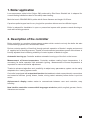
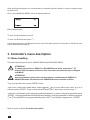
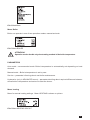
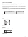
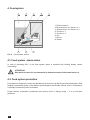
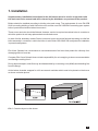
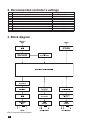
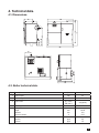
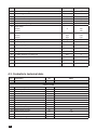
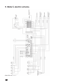
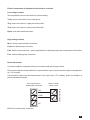
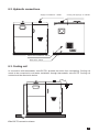
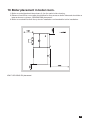
INSTRUCTION MANUAL
& SERVICE MANUAL
ORLIGNO 500
EV-20121003
MANUAL INSTRUCTION
CONTENTS
1. Boiler application . . . . . . . . . . . . . . . . . . . . . . . . . . . . . . . . . . . . . . . . . . . . . . . . . . . . . . . . . . . . . . . . 3
2. Description of the controller . . . . . . . . . . . . . . . . . . . . . . . . . . . . . . . . . . . . . . . . . . . . . . . . . . . . . . 3
2.1. Lightning up . . . . . . . . . . . . . . . . . . . . . . . . . . . . . . . . . . . . . . . . . . . . . . . . . . . . . . . . . . . 5
3. Controller’s menu description . . . . . . . . . . . . . . . . . . . . . . . . . . . . . . . . . . . . . . . . . . . . . . . . . . . . . 6
3.1. Menu handling . . . . . . . . . . . . . . . . . . . . . . . . . . . . . . . . . . . . . . . . . . . . . . . . . . . . . . . . 6
3.2. Alarm status and safety devices . . . . . . . . . . . . . . . . . . . . . . . . . . . . . . . . . . . . . . . . . 11
4. Feed system . . . . . . . . . . . . . . . . . . . . . . . . . . . . . . . . . . . . . . . . . . . . . . . . . . . . . . . . . . . . . . . . . . . 12
4.1. Feed system-alarm status . . . . . . . . . . . . . . . . . . . . . . . . . . . . . . . . . . . . . . . . . . . . . 12
4.2. Feed system protection . . . . . . . . . . . . . . . . . . . . . . . . . . . . . . . . . . . . . . . . . . . . . . . 12
5. Maintenance . . . . . . . . . . . . . . . . . . . . . . . . . . . . . . . . . . . . . . . . . . . . . . . . . . . . . . . . . . . . . . . . . . . 13
2
1. Boiler application
Low temperature pellet boiler Orligno 500 produced by Eko-Vimar Orlański Ltd. is adapted for
central heating installations also for hot utility water heating.
Main fuel use in ORLIGNO 500 is pellet with 6-8 mm diameter and length 10-50 mm.
Capacious pellet hopper lets for very long boiler operation without need to refill the hopper.
Boiler is adapted for installation in open or pressurized system with pressure vessel allowing to
work with working pressure.
2. Description of the controller
Boiler controller is a modern microprocessor system which controls not only the boiler but also
central heating system and hot domestic water.
Device controls quantity of feed fuel through periodic operation of feeder’s engine and amount
of supplied air for burning process. Thanks to semiconductor transmitters power of the blower is
fluently adjusted thus increasing reliability of control system of feeder’s engine.
Automatic burning up. Controller enables automatic burning up of the fuel on the burner.
Measurement of fumes temperature. Controller enables reading fumes temperature, it is
necessary for boiler operation with automatic igniting . Measurement of fumes temperature is
important for control and boiler adjustment.
Thanks to advanced algorithm and possibility to adjust many parameters; system can be easily
adapted to the heating system needs.
Controller is equipped with output test function that enables to check correct electric connections
and executive devices (pump, blower, feeder, mixing valve’s actuator) before boiler is put into
action.
Alphanumeric display makes easier to communicate between user and controller, easy
handling.
New intuitive controller’s menu with 6 languages at choice: polish, english, german, french,
lithuanian and russian.
3
Pic.1 Controller’s menu.
4
2.1. Burning up
1. Pour the pellets into the hopper and tightly close the lid.
2. Connect the main power plug into the 230V/50 socket.
TTENTION!
A
Socket should be protected with min. 10A fuse and 20 mA RCD (residual current
device).
3. Start the controller.
To start the controller it is necessary to press the „ON/OFF/ESC” button for 3 seconds. The same
operation with turning off the controller. Present status is shown on the display:
OFF – (active control of alarm parameters, manual mode of blower and feeder)
ON
TTENTION!
A
When „OFF” is shown on the display device is in standby mode and is still live. In
case of alarm controller will activate all pumps or feeders.
TTENTION!
A
It is forbidden to use for boiler lightning up any flammable substances.
If boiler is in idle time or maintenance is made it’s essential to unplug the boiler from the main power.
Display shows current state of individual devices. Picture shows main menu view.
Pic.2 Main display.
Last line on display shows through abbreviations active devices.
ABBR.
HP
WP
BU
LIG
fee
fa 20
M0
M1
DESCRIPTION
central heating pump operation
hot water pump operation
buffer pump operation
heating element operation
feeder operation
blower operation, current blower output
mixing valve closing
mixing valve opening
Tab.1 Abbreviation table with devices names.
5
After pouring the pellets it is recommended to manually start the feeder in order to transport fuel
to the burner.
Go to menu MANUAL MODE, which is displayed below:
Pic.3 Manual mode.
To turn on/off the feeder press
.
To turn on/off the blower press
.
Feeders should work until filling the burner with fuel. Next switch the controller in ON mode, fuel
will be automatically light up.
3. Controller’s menu description
3.1. Menu handling
Controller has two types of menus: SIMPLE MENU and ADVANCED MENU.
TTENTION !
A
To change type of menu: SIMPLE or ADVANCED press at the same time i
buttons. After 10 minutes of inaction from user menu will automatically be changed
on SIMPLE.
TTENTION !
A
Instruction manual contains all control parameters available both in SIMPLE or
ADVANCED menu. Parameters from ADVANCED menu are written in italics.
To go in to the main menu press „ENTER” button.
-main menu, written with capital letters, buttons
and
are for move within main menu, to go in to
submenu press „ENTER”. To go out from submenu press „ESC”. Main menu is shown on pic.1
-submenu is for displaying and changing operation parameters. In order to change the parameter press
„ENTER” . Changing parameter will be displayed periodically. Changing parameter on different one press
or . To withdraw from changed parameter press „ESC”. To accept the changes press „ENTER”.
Menu is shown in point 2 Controller description.
6
Pic.4 Main Menu
Menu Boiler
Boiler can operate in one of two operation modes: manual and auto.
Pic.5 Menu BOILER
TTENTION !
A
Operation modes decide only about setting method of the boiler temperature.
PARAMETERS
Auto mode – recommended mode. Boiler’s temperature is automatically set depending on heat
demand.
Manual mode – Boiler’s temperature is set by user.
Service – parameter informing about next boiler maintenance.
Hysteresis (only in ADVANCED menu) – parameter deciding about required difference between
actual boiler’s temperature and set one to start the burner.
Menu heating
Menu for central heating settings. Menu HEATING is shown on picture.
Pic.6 Menu HEATING CIRCUIT
7
PARAMETERS
Progr. – kept temperature in heating circuit (radiators, underfloor heating) during demand from room
thermostat.
Heating – parameter for turning off/on heating.
Reduction (only in ADVANCED menu) – parameter for adjusting the temperature value .
TTENTION!
A
In case if mixing valve with actuator is not installed in central heating circuit,
parameters „progr” and „ reduction” are turned off.
TTENTION!
A
In case if mixing valve with actuator is not installed in central heating circuit, during
the first start of the boiler, parameter „mixer” need to changed on „no” in SERVICE
menu.
Menu hot water
Pellet boiler is perfectly matched for hot water heating both during the heating season and summer
season. Menu HOT WATER is shown below:
Pic.7 Menu HOT WATER.
PROGR. H.W. (PROGRAMMED HOT WATER)
Hot water tank need to be equipped with temperature sensor.
PARAMETERS:
Programmable hot water temperature (progr. h.w.) – hot water temperature kept in the tank.
Hot water – parameter for turning on/off hot water function.
Priority (only in ADVANCED menu) – with priority parameter “on” during hot water heating rest of the
pumps in the installation are off in order to faster heat the water.
Hysteresis (only in ADVANCED menu) – temperature value that need to decrease temperature of hot
water to start heating hot water and temp. value that need to increase to turn off hot water heating.
Boiler h.w. + (only in ADVANCED menu) – temperature value that need to increase to programmed
temperature during hot water heating. i.e. if programmed temp of hot water = 60ºC and “boiler h.w.+” =
10 ºC then programmed temperature during heating hot water is 70ºC.
8
ADVANCED PRIORITY OF HOT WATER
Controller can operate in two modes of hot water heating ( known only in gas and oil boilers): hot water
priority ( recommended) and without priority. During boiler operation with priority mode with hot water
heating, works only hot water pump reaching set temp. much faster.
In order to avoid temperature drop in the house during hot water heating and the pump works longer than
20 minutes ( pre-set) and programmed temperature of hot water is not reached; central heating pump
will start working on 5 minutes.
Parameters available in service menu: „ stop central heating pump with hot water pump” ( stop HP/HWP)
and „ work central heating pump with hot water pump ”( work HP/HWP).
Pic.8 Pump operation during hot water heating in priority mode
Input menu
Input menu shows temperatures from all connected sensors to the controller . Input menu view is shown
below:
Pic.9 Input menu.
Buffer menu
Menu for adjustment of buffer parameters. Buffer menu view is shown below:
Pic.10 Buffer menu
9
PARAMETERS
Programmed top – programmable temperature in the upper part of the buffer.
Programmed down – programmable temperature in the upper part of the buffer.
OPERATION DESCRIPTION
Buffer pump will be on, when temperature in upper part of the buffer drops below programmed
temperature.
Buffer charging lasts until both programmed temperatures are reached.
TTENTION
A
Buffer menu is only available in ADVANCED menu..
PARAMETERS
Burner power – available in two modes: auto (recommended) and manual. In auto mode: controller
selects burner power accordingly to energy demand of the house.
Programmed power – in auto mode is displayed actual power of the burner , in manual mode burner
power can be set as a constant.
ATTENTION!
Burner menu is only available in ADVANCED menu.
Language menu
Controller is equipped with multilingual menu: polish, english, german, french, lithuanian and russian.
Language selection is made in Language menu.
10
3.2. Alarm status and safety devices
Alarm status is indicated with blinking backlight on the controller’s display. After pressing „ENTER”, type
of alarm is displayed. Types of alarms:
-boiler overheating;
Alarm is indicated after exceeding 97ºC (pre-set) on the boiler. Controller will activate all connected
pumps until temperature will decrease.
TTENTION!
A
With temperature 2ºC lower than alarm temperature, pumps are activated in a
initial alarm mode. If temperature do not exceed alarm temperature it will not be
remembered in controller’s memory.
-no fuel/fire;
Alarm is activated in case of lack of fuel or fire in the burner.
-feeder overheating;
Alarm is activated when permissible feeder’s temperature is exceeded.
TTENTION!
A
After noticing alarm status, it is recommended to determine cause and remove it.
-thermal boiler protection independent from boiler’s controller In case of exceeding boiler’s
temperature of 94ºC thermal boiler protection will turn off blower.
TTENTION!
A
After alarm occured it is recommended to determine cause of alarm, remove it and
manually unblock thermostat.
11
4. Feed system
1. Pellet container
2. Motoreductor of a feeder no 1
3. Motoreductor of a feeder no 2
4. Feeder no 1
5. Feeder no 2
6. Fan
7. Burner
8. Heater
Pic.11 Feed system section
4.1. Feed system –alarm status
In case of exceeding 60°C in the feed system, alarm is activated with blinking display „feeder
overheating”.
TTENTION!
A
After alarm occured it is recommended to determine cause of alarm and remove it.
4.2. Feed system protection
Feed system is designed in such a way that flame from burner is not able to get to the pellet hopper. Safe
feeding is assured by system of two feeders jointed together with flexible, vertical chute. Fuel feeding is
continually monitored by boiler’s controller.
Proper feeders cooperation guarantees that vertical chute is always empty – it is a burn-back
protection.
12
5. Maintenance.
Ash created during pellet burning is deposited in the bottom chamber. Bottom chamber needs to
be cleaned once a month with tools: scraper, cleaning shield. It is advisable to clean heat exchanger
at least once a month to assert permeability of pipes.
If fumes temperature exceeds max. value which will be displayed it is necessary to clean heat
exchanger pipes and boiler.
Once a week burner need to be checked thoroughly because of possibility of depositing unburned
parts of pellets (especially when pellet quality is bad) which may block pellet feeding and cause
uncontrolled burning.
ttention!
A
If unproper pellet issue will repeat it is necessary to fully open blower’s screen.
ttention!
A
It is necessary to remove pellets from tank, upper and bottom auger in case if boiler is
not used for over 2 weeks.
In order to clean heat exchanger:
1. Open upper door
2. Unscrew two nuts with M13 wrench ( they secure heat exchanger’s plate behind which
horizontal pipes are placed).
3. Remove turbulators and clean pipes with shield and turbulators with brush.
4. Place turbulators back into the heat exchanger.
ttention!
A
If unproper pellet issue will repeat it
is necessary to fully open blower’s
screen.
Pic.12 Turbulators
Steps for door correct regulation:
adjusting nut
a) disassembly the door
b) loosen the adjusting nut
c) turn the hinge at 360°
d) tighten up an adjust nut.
arning!
W
Regulation should be made on both upper and bottom hinges at the same time. All
threaded door parts should be greased periodically (for exemple with a grease or an
oil) as well as hinges.
13
SERVICE MANUAL
CONTENTS
1. Installation . . . . . . . . . . . . . . . . . . . . . . . . . . . . . . . . . . . . . . . . . . . . . . . . . . . . . . . . . . . . . . . . . . . . . 15
2. Recommended controller’s settings . . . . . . . . . . . . . . . . . . . . . . . . . . . . . . . . . . . . . . . . . . . . . . 16
3. Block diagram . . . . . . . . . . . . . . . . . . . . . . . . . . . . . . . . . . . . . . . . . . . . . . . . . . . . . . . . . . . . . . . . . . 16
4. Technical data . . . . . . . . . . . . . . . . . . . . . . . . . . . . . . . . . . . . . . . . . . . . . . . . . . . . . . . . . . . . . . . . . . 17
4.1. Dimensions . . . . . . . . . . . . . . . . . . . . . . . . . . . . . . . . . . . . . . . . . . . . . . . . . . . . . . . . . . 17
4.2. Boiler technical data . . . . . . . . . . . . . . . . . . . . . . . . . . . . . . . . . . . . . . . . . . . . . . . . . . 17
4.3. Controller’s technical data . . . . . . . . . . . . . . . . . . . . . . . . . . . . . . . . . . . . . . . . . . . . . 18
4.4. Electric data of gear-motors . . . . . . . . . . . . . . . . . . . . . . . . . . . . . . . . . . . . . . . . . . . 19
4.5. Mechanical data of gear-motors . . . . . . . . . . . . . . . . . . . . . . . . . . . . . . . . . . . . . . . . 19
4.6. Heater’s technical data . . . . . . . . . . . . . . . . . . . . . . . . . . . . . . . . . . . . . . . . . . . . . . . 19
5. Boiler’s electric scheme . . . . . . . . . . . . . . . . . . . . . . . . . . . . . . . . . . . . . . . . . . . . . . . . . . . . . . . . . 20
6. Boiler connection . . . . . . . . . . . . . . . . . . . . . . . . . . . . . . . . . . . . . . . . . . . . . . . . . . . . . . . . . . . . . . . 22
6.1. Connection scheme . . . . . . . . . . . . . . . . . . . . . . . . . . . . . . . . . . . . . . . . . . . . . . . . . . . 22
6.2. Hydraulic connections . . . . . . . . . . . . . . . . . . . . . . . . . . . . . . . . . . . . . . . . . . . . . . . . 23
6.3. Cooling coil . . . . . . . . . . . . . . . . . . . . . . . . . . . . . . . . . . . . . . . . . . . . . . . . . . . . . . . . . . 23
7. Boiler tightness . . . . . . . . . . . . . . . . . . . . . . . . . . . . . . . . . . . . . . . . . . . . . . . . . . . . . . . . . . . . . . . . . 24
8. Ventilation . . . . . . . . . . . . . . . . . . . . . . . . . . . . . . . . . . . . . . . . . . . . . . . . . . . . . . . . . . . . . . . . . . . . . 24
8.1. Supply air ventilation . . . . . . . . . . . . . . . . . . . . . . . . . . . . . . . . . . . . . . . . . . . . . . . . . . 24
8.2. Exhaust ventilation . . . . . . . . . . . . . . . . . . . . . . . . . . . . . . . . . . . . . . . . . . . . . . . . . . . 24
9. Chimney connection . . . . . . . . . . . . . . . . . . . . . . . . . . . . . . . . . . . . . . . . . . . . . . . . . . . . . . . . . . . . 24
10. Boiler placement in boiler room . . . . . . . . . . . . . . . . . . . . . . . . . . . . . . . . . . . . . . . . . . . . . . . . . . 25
11. Troubleshooting . . . . . . . . . . . . . . . . . . . . . . . . . . . . . . . . . . . . . . . . . . . . . . . . . . . . . . . . . . . . . . . . 26
12. Ending . . . . . . . . . . . . . . . . . . . . . . . . . . . . . . . . . . . . . . . . . . . . . . . . . . . . . . . . . . . . . . . . . . . . . . . 27
14
1. Installation
Supplementary installation instructions for the UK market are to be read in conjunction with
the main instruction manual and will be issued by the distributor on purchase of the product.
Boilers should be installed according to binding rules and norms. The requirements of norm PN 87/B
02411 according building of solid fuel boiler room and the norm PN 91/B 02413 according open system
boilers’ production should be taken into account.
These norms and rules should be followed, however, caution is required as national rules in countries to
which the product is sold may replace above mentioned norms.
In case of boiler assembly outside Poland, rules and norms should be followed according to solid fuel
boiler assembly in countries in which the boiler is sold. Boiler ORLIGNO 500 is adjusted for installation
in pressurized systems.
Eko-Vimar Orlanski Ltd. recommends to use stainless steel flue liners that protect the chimney from
damaging effect of wood tar.
Company Eko-Vimar Orlanski does not take responsibility for not complying to above recommendation
and damage resulting from it.
During boiler transport, boiler flue may be disassembled by unscrewing nuts (8xM8) and detaching flue
from the flange.
At the bottom chamber wrapped in a foil are ceramic moulders which need to be placed on the burner
as shown on below picture.
Pic.1 Ceramics layout on the burner
15
2. Recommended controller’s settings
Lp.
1.
2.
3.
4.
5.
6.
7.
8.
9.
10.
Description
Boiler operation
Heating temperature
Underfloor heating temperature max
Thermostat
Hot water temperature
Priority
Hysteresis
Boiler h.w.
Buffer upper temperature
Buffer down temperature
3. Block diagram
Pic.2 Controller’s block diagram.
16
Programmed parameter
Auto mode
60°C
45°C
-15°C
45°C
yes
2°C
+10°C
60°C
80°C
4. Technical data.
4.1. Dimensions.
4.2. Boiler technical data.
L.p. Description
j.m.
Value
1. Boiler output
2. Power range
kW
kW
25
from 7 to 25
3. Boiler class
acc. norm
EN 303-5
%
4. Efficiency
5. Fuel: pellets
lengWh
diameter
moisture content
6. Fuel consumption:
nominal
minimal
3 (highest)
~91
mm
mm
%
10-50
6-8
8-12
kg/h
kg/h
5,5
1,5
17
L.p. Description
7.
8.
9.
10.
11.
12.
13.
Approximate heating space
Max working pressure
Max water temp.
Min. return water temp.
Flue diameter
Required chimney draught
Fumes temp:
nominal
minimal
14. Fumes flow:
nominal
minimal
15. Weight
16. Water capacity
17. Hopper capacity
j.m.
Value
m2
bar
°C
°C
mm
mbar
to 250
2,5
85
60
10
from 0,1 to 0,2
°C
160
130
kg/s
kg/s
kg
l
0,02
0,01
320
60
l
255
18. Loading opening dimensions width/length
mm
19. Cooling coil water temperature
°C
20. Min water pressure in cooling coil
21. Voltage/Frequency AC
22. Auxiliary power
23. Recommended capacity of accumulation tank
260/432
10
bar
2
V/Hz
230/50
W
250
litres
1000-2000
4.3. Controller’s technical data .
L.p.
1.
2.
3.
4.
5.
6.
7.
8.
9.
10.
11.
12.
13.
14.
15.
16.
18
Description
Power AC
Power consumption (controller)
Central heating pump
Hot water pump
Buffer pump
Heater
Blower
Gear-motor 1
Gear-motor 2
Mixing valve actuator
Boiler temp. range
Hot water temp. range
Measurement accuracy
Ambient temperature
Moisture content
Alarm temp. - range
j.m.
~V/Hz
VA
OUTPUT LOAD
W
W
W
W
W
W
W
W
ºC
ºC
ºC
ºC
%
ºC
Value
230/50±10%
<5
100
100
100
400
150
200
150
50
60-85
35-70
±2
0-60
5-95 without condensation
80-95
4.4. Electric data of gear-motors.
Lp.
Description
Value
j.m.
1.
Type – motor with gear
-
-
2.
Voltage AC
~V/Hz
230/50
3.
Pole number
P
2
4.
Motor characteristic without load
Power
Input power
Rotation speed
Start voltage
A
W
rot/min
V
0,65 ± 15%
72 ± 15%
5,4 ± 10%
161 MAX
5.
Load characteristic – after 1 min since start of motor
Limit load
Acceptable load
Start load
Nm
Nm
Nm
33 MIN
25 MlN
20 MIN
6.
Max current
A
1,2 MAX
7.
Dielectric resistance
Motor resistant voltage: 1500V RMS through 1 min
(1800V RMS through 1 sec) measured between coil and motor’s core (test
current 3 mA
-
-
8.
Insulation coefficient 100 MΩ minimum at 500V of voltage measured
between coil and cover
-
-
9.
Thermal protection: Motor protected up 120°C
10.
Insulation class
-
-
klasa
„E”
4.5. Heater’s technical data
L.p.
Description
1.
Lubrication – Mineral oil and grease
2.
j.m.
Value
-
-
Noisness (without load)
dB
25 MAX
3.
Weight
kg
2,2
4.
Shaft position - horizontal
-
-
5.
Shift
-
1 : 532
4.6. Heater’s technical data
L.p.
Description
1.
Type - GLO 120 - 400
2.
Input voltage range ( cooperate with adapter 230/120
VAC )
3.
Current
4.
Heater power
6.
Heater temperature
7.
Time for warm. up to 1200°C
9.
10.
j.m.
Value
-
-
V-AC
120 -15%/+10% (102 – 132)
A/V-AC
3,3 - 4,2/120
W
400
°C
1200
sek.
>12
Heater material: ceramic – recrystallised Si3N4
-
-
Safety norm CSA
-
19
5. Boiler’s electric scheme.
Pic.3 Electric scheme.
20
Electric connection of equipment to the boiler’s controller.
Low-voltage contact
Tco- temperature sensor connection for central heating
Tcwu- sensor connection for hot water pump
Tbg- sensor connection in upper part of the buffer
Tbd- sensor connection in down part of the buffer
Rpok- room thermostat connection
High-voltage contact
M.co- mixing valve’s actuator connection
P.cwu- hot water pump connection
P.bu- buffer pump connection – pump responsible for maintaining right return temperature to the boiler
P.co- central heating pump connection
Room thermostat
Controller enables to cooperate with any room thermostat with closing contact.
Room thermostat should be installed in a representative room in the house with respect to temperature
at 1,5-2 m height.
One shouldn’t install room thermostat close to any heat source (TV, radiator), direct sun radiation or
places exposed to draught.
Room thermostat ex.
EUROSTER, AURATON
COM
Room thermostat
NO
Boiler controller
Pellets control
NC
Pic.4 Room thermostat connection.
21
6. Boiler connection.
6.1. Connection scheme.
16
8
17
5
14
4
3
1
2
13
20
9
6
7
10
11
21
15
18
12
19
Pic.5 Boiler connection scheme.
Connection scheme
1. Pellet boiler ORLIGNO 500
2. Buffer-boiler pump
3. Supply manifold
4. Three-way mixing valve
5. Circulation pump
6. Differential valve
7. Return manifold
8. Radiator
9. Hot water pump
10. Hot water tank
11. Hot water outlet
12. Cold water inlet
13. Pressure tank
14. Safety group
15. Buffer tank
16. Set of solar collectors
17. central heating sensor
18. Upper part sensor
19. Down part sensor
20. Solar collector pump
21. Hot water measurement
22
6.2. Hydraulic connections.
Supply to installation. – DN 50
Cooling coil tappings– 2 × DN 20
Return from installation – DN 50
Drain valve – DN 15
6.3. Cooling coil
In connection with thermostatic valve BVTS it protects the boiler from overheating. Cooling coil
needs to be connected to cold water installation through thermostatic valve BVTS. Cooling coil
outlet should be directed to drains.
Pic.6 BVTS connection scheme
23
7. Boiler tightness
It is very important to assure boiler tightness especially: door tightness. Leakiness causes that fumes
may get out to the boiler room and lead to uncontrolled burning. To assure proper door tightness, rope
need to be checked periodically and in case of damage - replaced. Insulation rope in bottom door need
to greased at least once a month with oil or graphite grease.
8. Ventilation
According to european safety regulations each boiler room should have supply-exhaust ventilation
ensuring correct boiler operation and user’s safety. Lack of ventilation or its obstruction is the main
reason of incorrect boiler operation (i.e. boiler cannot reach set temperature). Exhaust ventilation
removes from boiler room used air and harmful gases. Boiler room with natural draught cannot have
installed mechanical ventilation.
8.1. Supply air ventilation.
1. Ventilating duct section should have at least 50% area of chimney’s section and not less than 20 x 20
cm. Duct should be placed 1m above the floor.
2. Ventilating duct should have installed device for air flow control; device shouldn’t limit duct section
above 1/5.Ventilating duct should be made of non-inflammable material.
8.2. Exhaust ventilation
1. Exhaust duct should be made of bricks with section of at least 25% of chimney section not less 14 x 14
cm. Inlet hole cannot have any devices that reduce its section. Outlet hole should be placed close to the
ceiling led out 1,5 m above the roof. Ventilating duct should be made of non-inflammable material.
2. Height of the boiler room min. 2,2 m.
9. Chimney connection
Chimney ducts should be installed according to binding rules and norms in countries to which boilers
are sold.
Part of chimney system connection boiler with chimney is called flue. In order to lower flow resistance of
exhaust gases this part should lead as a straight pipe with, if necessary, joints up to 45°
Because of exhaust gases temperature ORLIGNO 500’s need to be connected to chimney system
protected against condensate soaking.
30 cm above the floor closing door should be installed with tight closing.
Chimney section should be round or close to square shape because of low flow resistance. Minimal flue
diameter at least 160 mm. Chimney should lead above the roof. Chimney outlet location is dependent on
roof slope and its combustibility.
Eko-Vimar Orlański Ltd. recommends to install draught regulator which stabilizes chimney draught.
24
10. Boiler placement in boiler room.
1. Boiler room height should be at least >2,2 m for easier boiler cleaning.
2. Distance from boiler room walls should allow for free access to boiler sides and should be at
least as shown on picture „ORLIGNO 500 placement”.
3. Boiler room should be free of any electric installation not intended for boiler installation.
Pic.7 ORLIGNO 500 placement.
25
11. Troubleshooting
Symptom
Alarm: No fire/fuel
Boiler
cannot reach
programmed
temp.
Boiler is fuming
Door is fuming
Controller doesn’t
work
Loud blower
operation
26
Reason
Action
Lack of fire
Refill hopper acc. to point „Lightning up”
Wrong lightning up
Check „Lightning up”
Too moisture pellet
Check moisture – use pellet with required
parameters
Clogged primary air channels
Call service – after-warranty service
Clogged heat exchanger’s pipes
Clean pipes or call service – after warranty
service
Damaged gasket on blower’s or
burner’s flange
Replace – after-warranty service
Damaged blower
Replace – after-warranty service
Clogged or unproper chimney
Get the chimney-sweeper opinion
Strong wind forces fumes into the
chimney
Consider installation of devices regulating
chimney draught
Gasket leak
Regulate the door’s hinges
Damaged rope
No voltage in the grid
Damaged wire
Replace the rope – after-warranty service
Check the protection devices in the electric
installation
Wire and connection control
Damaged controller
Call the service
Damaged bearings
Damaged capacitor
Loosen fixing of blower
Dirty rotor blades
Call the service - replace the blower
Call service – replace the capacitor
Fixing control, screw in
Control, cleaning
12. Ending
Present appliance is marked according to European Directive 2002/96/EC on waste electrical and
electronic equipment.
Symbol placed on the components or attached documents means that appliance is not classified as a
household waste.
Scrapping should take place in special collection point in order to reuse electrical and electronic
components.
The Clean Air Act 1993 and Smoke Control Areas
Under the Clean Air Act local authorities may declare the whole or part of the district of the
authority to be a smoke control area. It is an offence to emit smoke from a chimney of a building,
from a furnace or from any fixed boiler if located in a designated smoke control area. It is also an
offence to acquire an «unauthorised fuel» for use within a smoke control areaunless it is used
in an «exempt» appliance («exempted» from the controls which generally apply in the smoke
control area).
The Secretary of State for Environment, Food and Rural Affairs has powers under the Act to
authorise smokeless fuels or exempt appliances for use in smoke control areas in England. In
Scotland and Wales this power rests with Ministers in the devolved administrations for those
countries. Separate legislation, the Clean Air (Northern Ireland) Order 1981, applies in Northern
Ireland. Therefore it is a requirement that fuels burnt or obtained for use in smoke control areas
have been «authorised» in Regulations and that appliances used to burn solid fuel in those
areas (other than «authorised» fuels) have been exempted by an Order made and signed by the
Secretary of State or Minister in the devolved administrations.
Further information on the requirements of the Clean Air Act can be found here:
http://smokecontrol.defra.gov.uk/
Your local authority is responsible for implementing the Clean Air Act 1993 including designation
and supervision of smoke control areas and you can contact them for details of Clean Air Act
requirements
The Angus Orligno 500 has been recommended as suitable for use in smoke control areas when
burning wood pellets 6-8mm diameter and length of 10-50mm.
27
For UK sales, service and acquisition of spares.
Eco Angus Ltd
Unit 3G, Burnett Industrial Estate
Cox's Green
Wrington
North Somerset
BS40 5QR
[t] 01934 862642
www.ecoangus.co.uk
EKO-VIMAR ORLAŃSKI Sp. z o.o.
48-385 Otmuchów, ul. Nyska 17b
POLSKA / woj. opolskie
T +48 77 400 55 80-81, 400 55 91
F +48 77 439 05 03, 400 55 96
E [email protected]
www.orlanski.pl
User manual reference number A001 version 1 13.12.2012