1
I
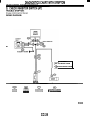
2002 IMPREZA SERVICE MANUAL
QUICK REFERENCE INDEX
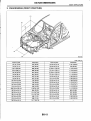
BODY SECTION
c-
This service manual has been prepared
to provide SUBARU service personnel
with the necessary information and data
for the correct maintenance and repair
of SUBARU vehicles.
This manual includes the procedures
for maintenance, disassembling, reassembling, inspection and adjustment of
components and diagnostics for guidance of experienced mechanics.
Please peruse and utilize this manual
fully to ensure complete repair work for
satisfying our customers by keeping
their vehicle in optimum condition.
When replacement of parts during
repair work is needed, be sure to use
SUBARU genuine parts.
All information, illustration and specifications contained in this manual are
based on the latest product information
available at the time of publication
approval.
FUJI HEAVY INDUSTRIES LTD.
Gl830BE6
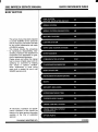
HVAC SYSTEM
(HEATER. VENTILATOR AND A/C)
ACa
..
1.
2.
3.
4.
5.
6.
7.
8.
9.
10.
11.
12.
13.
14.
15.
16.
17.
18.
19.
20.
21 .
Page
General Description .................................................................................... 2
Refrigerant Pressure with Manifold Gauge Set ......................................... 15
Refrigerant Recovery Procedure............................................................... 16
Refrigerant Charging Procedure ............................................................... 17
Refrigerant Leak Check ............................................................................ 20
Compressor Oil .........................................................................................
21
Blower Motor Unit Assembly ..................................................................... 22
Blower Resistor ......................................................................................... 23
Heater Core............................................................................................... 24
Control Unit ............................................................................................... 25
Compressor............................................................................................... 26
Condenser................................................................................................. 27
Heater and Cooling Unit ............................................................................ 28
Evaporator................................................................................................. 29
Hose and Tube .......................................................................................... 30
Relay and Fuse ......................................................................................... 31
Pressure Switch (Dual Switch) .................................................................. 32
Air Vent Grille ............................................................................................ 33
Heater Duct ............................................................................................... 34
Heater Vent Duct....................................................................................... 35
General Diagnostics.................................................................................. 36
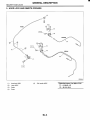
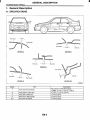
GENERAL DESCRIPTION
HVAC SYSTEM (HEATER, VENTILATOR AND N C )
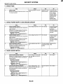
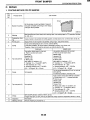
1. General Description
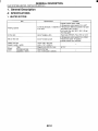
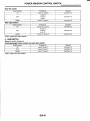
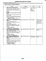
A: SPECIFICATIONS
1. HEATER SYSTEM
Item
Heating capacity
Condition
Mode selector switch: HEAT
Temperature control switch: FULL HOT
5.0 kW (4,300 kcal/h, 17,062 BTU/ Temperature difference between hot water
and inlet air: 65°C (149°F)
h) or more
Hot water flow rate: 360 Q (95.1 US gal,
79.2 Imp gal)/h
SDecifications
Air flow rate
280 m3 (9,888 cu ft)/h
Heat mode (FRESH), FULL HOT at 12.5 V
Max air flow rate
450 m3 (15,892 cu ft)/h
Temperature control switch: FULL COLD
Blower fan speed: 4th position
Mode selector lever: RECIRC
Heater core size
(height x length x width)
163.9 x 200 x 25.0 mm
(6.45 x 7.87 x 0.984 in)
Maanet motor 200 W or less
Sirocco fan type
150 x 75 mm (5.91 x 2.95 in)
Blower
motor
Type
Fan type and size
(diameter x width)
AC-2
at 12 V
I
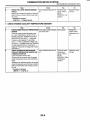
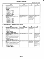
Specifications
Item
1
5.1 kW
(4.385 kcal/h. 17,402 BTU/h)
HFC-134a (CH,FCF,)
[0.5f0.05 kg (0.99f0.11 Ib)]
Vane rotary, fix volume (CR-14)
Cooling capacity
Refrigerant
Type
Discharge
Compressor
144 cm3 (8.79 cu in)/rev
7,000 rpm
Drv, single-disc type
47 w
V-Ribbed 4 PK
125 mm (4.92 in)
1.064
Corrugated fin (Sub cool type)
Max. permissible speed
Tvpe
Power consumption
Type of belt
Pulley dia. (effective dia.)
Pulley ratio
Magnet clutch
Type
c
e alea
I Core thickness
I
Condenser
c-
Effective inner capacity
Type
Receiver drier
Expansion valve
I
I
I
I Radiation area
~
I
Evaporator
Blower fan
1 Condenser fan (Sub fan)
Radiator fan (Main fan)
ldlina SDeed 1NC ON)
. , I
TvDe
Dimensions (W x H x T)
Fan type
Outer diameter x width
Power consumption
Motor t w e
I Power consumption
I Fan outer diameter
Motor type
Power consumption
Fan outer diameter
I MPFI model
ON -+ OFF
Low-pressure switch
operating pressure
Dual switch
(Pressure switch)
High-pressureswitch
operating pressure
0.21 m2 (2.26 sq ft)
16 mm (0.63 in)
I
I
I
5.34 m2 157.5 sa ft)
250 cm3 (15.26 cu in)
Internal equalizing
Sinale tank
255 x 200 x 48 mm
(10 x 7.87 x 1.89 in)
Sirocco fan
150 x 75 mm (5.91 x 2.95 in)
200 W at 12 V
Magnet
70 W at 12 V
320 mm (12.6 in)
Magnet
70 W at 12 V
320 mm (12.6 in)
850f100 rpm
278f29 kPa
(2.83+0.3 kg/cm2,40.3f4.2 psi)
287+39/L25kPa
OFF + ON
(2.9+0.4/-0.25
kg/cm2,42+5.7
/-3.6Psi)
2,800f100 kPa
(29fl kg/cm2, 406+15 psi)
600f200kPa
(6.12f2 kg/cm2, 87229 psi)
ON -+ OFF
DlFF
~
Diff. 2.5*0.5"C(36.5&0.9"F)
Thermo control amplifier working temperature
(Evaporator outlet air)
OFF
ON
1.5zkO.5"C(35+0.9"F)
HV004!
AC-3
GENERAL DESCRIPTION
HVAC SYSTEM (HEATER. VENTILATOR AND A/C)
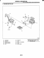
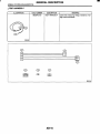
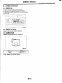
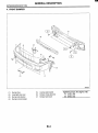
B: COMPONENT
1. HEATER COOLING UNIT
~~
(1)
(2)
(3)
(4)
(5)
(6)
(7)
(8)
(9)
Unit cover
Side link
Mode acutuator lever
Foot lever
Spring
Mode acutuator link
Defroster lever
Foot nozzle
Unit duct cover
(10) Heater core
(11) Drain hose
(12) Mix acutuator lever
(13) Unit assembly
(14) Foot duct
(15) Clip
(16) Packing
(17) Cooling unit block
(18) O-ring
AC-4
(19)
(20)
(21)
(22)
Expansion valve
Evaporator
Evaporator cover
Thermistor
Tightening torque: N.m (kgf-m, ft-lb)
T: 7.35 (0.750, 5.421)
I
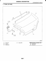
GENERAL DESCRIPTION
HVAC SYSTEM (HEATER, VENTILATOR AND NC)
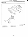
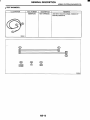
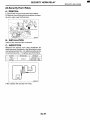
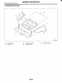
2. BLOWER MOTOR UNIT
(1)
(2)
(3)
(4)
Upper case
Blower link
Blower link lever A
Blower link lever B
(5)
Clip
(6)
(7)
Filter cover
Filter
(8)
(9)
(10)
Blower motor assembly
Hose
Blower resistor
AC-5
Tightening toque: N-m (kgf-m, ft-lb)
T: 7.35 (0.750,5.421)
GENERAL DESCRIPTION
HVAC SYSTEM (HEATER. VENTILATOR AND A/C)
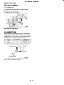
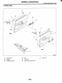
3. CONTROL UNIT
HV0054
(1)
(2)
(3)
Dial
Fan control plate
Temperature control plate
(4)
(5)
Mode control plate
Heater control knob
(6)
(7)
(8)
(9)
Heater control panel
Air conditioner knob
Plug knob
Heater control base
(IO) Intake cable
AC-6
(1 1) Mode cable
(12) Temperature cable
(13) Bulb
(14) Fan switch ASSY
(15) Harness
I
GENERAL DESCRIPTION
HVAC SYSTEM (HEATER, VENTILATOR AND NC)
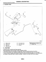
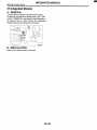
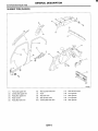
4. AIR CONDITIONING UNIT
(5)
HV0055
(1)
(2)
(3)
(4)
(5)
Condenser
Hose (High-pressure)
Hose (Low-pressure)
Bracket
Compressor
(6)
(7)
Tightening torque: N-m (kgf-m, ft-lb)
T1: 7.4 (0.75, 5.4)
O-ring
ClampA
(8)
(9)
Clamp B
Tube (To condenser)
(IO) Tube (To evaporator)
AC-7
T2: lS(1.5, 10.8)
I
GENERAL DESCRIPTION
HVAC SYSTEM (HEATER, VENTILATOR AND A/C)
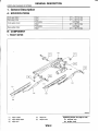
5. COMPRESSOR
HV0051
(1)
(2)
(3)
(4)
(5)
(6)
Idler pulley bracket
Idler pulley adjuster
Idler pulley
Compressor bracket upper
Compressor
Compressor bracket lower
(7)
(8)
V-belt
Compressor belt cover
AC-8
Tightening torque: N.m (Irgf-m, ft-lb)
TI: 7.4 (0.75, 5.4)
T2: 22.6(2.3, 16.6)
T3: 23.0 (2.35, 17.0)
T4: 28.9 (2.95, 21.3)
T5: 35 (3.6,26)
I
GENERAL DESCRIPTION
HVAC SYSTEM (HEATER, VENTILATOR AND NC)
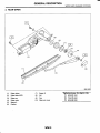
6. HEATER DUCT
HV0056
(1)
(2)
(3)
Front defroster nozzle
Side defroster duct (LH)
Side defroster duct (RH)
(4)
(5)
(6)
Side ventilation duct (LH)
Side ventilation duct (RH)
Rear heater duct (LH)
AC-9
(7)
Rear heater duct (RH)
I
GENERAL DESCRIPTION
HVAC SYSTEM (HEATER. VENTILATOR AND N C )
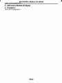
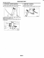
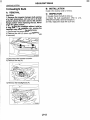
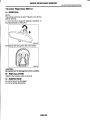
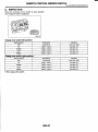
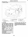
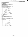
C: CAUTION
1. HFC-134A A/C SYSTEM
Unlike the old conventional HFC-12 system components, the cooling system components for the
HFC-134a system such as the refrigerant and compressor oil are incompatible.
Vehicles with the HFC-134a system can be identified by the label “ A attached to the vehicle.
Before maintenance, check which A/C system is installed in the vehicle.
2. COMPRESSOR OIL
HFC-134a compressor oil has no compatibility
with that for R12 system.
Use only the manufacturer-authorized compressor oil for the HFC-134a system; only use DH-PR.
Do not mix multiple compressor oils.
If HFC-12 compressor oil is used in a HFC-134a
A/C system, the compressor may become stuck
due to poor lubrication, or the refrigerant may leak
due to swelling of rubber parts.
On the other hand, if HFC-134a compressor oil is
used in a HFC-12 A/C system, the durability of the
A/C system will be lowered.
HFC-134a compressor oil is very hygroscopic.
When replacing or installing/removing A/C parts,
immediately isolate the oil from the atmosphere using a plug or tape. In order to avoid moisture, store
the oil in a container with its cap tightly closed.
4. HANDLING OF REFRIGERANT
The refrigerant boils at approx. -30°C (-22°F).
When handling it, be sure to wear safety goggles
and protective gloves. Direct contact of the refrigerant with skin may cause frostbite.
If the refrigerant gets into your eye, avoid rubbing
your eyes with your hands. Wash your eye with
plenty of water, and receive medical treatment from
an eye doctor.
Do not heat a service can. If a service can is directly heated, or put into boiling water, the inside
pressure will become extremely high. This may
cause the can to explode. If a service can must be
warmed up, use hot water in 40°C (104°F) max.
Do not drop or impact a service can. (Observe
the precautions and operation procedure described
on the refrigerant can.)
When the engine is running, do not open the
high-pressure valve of the manifold gauge. The
high-pressure gas will back-flow resulting in an explosion of the can.
The refrigerant is non-toxic and harmless under
normal operating circumstance, but it may change
to phosgene (a noxious fume) under open flames
or high temperatures (caused by a cigarette or
heater).
Provide good ventilation and do not work in a
closed area.
Never perform a gas leak test using a halide
torch-type leak tester.
In order to avoid destroying the ozone layer, prevent HFC-134a from being released into the atmosphere. Using a refrigerant recovery system,
discharge and reuse it.
Goggles
Gloves
3. REFRIGERANT
The HFC-12 refrigerant cannot be used in the
HFC-134a A/C system. The HFC-134a refrigerant,
also, cannot be used in the HFC-12 A/C system.
If an incorrect or no refrigerant is used, poor lubrication will result and the compressor itself may
be damaged.
Avoid open
flame
No direct heat
on container
Do not
discharge
Loosen
G4M097S
AC-10
a
GENERAL DESCRIPTION
HVAC SYSTEM (HEATER, VENTILATOR AND NC)
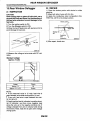
5. O-RING CONNECTIONS
Use new O-rings.
In order to keep the O-rings free of lint which will
cause a refrigerant gas leak, perform operations
without gloves and shop towels.
Apply the compressor oil to the O-rings to avoid
sticking, then install them.
Use a torque wrench to tighten the O-ring fittings:
Over-tightening will damage the O-ring and tube
end distortion.
If the operation is interrupted before completing a
pipe connection, recap the tubes, components, and
fittings with a plug or tape to prevent contamination
from entering.
Use the oil specified in the service manual to Iubricate the O-rings.
Apply the oil to the top and sides of the O-rings before installation.
Apply the oil to the area including the O-rings and
tube beads.
HV0062
Kea'
After tightening, use a clean shop towel to remove excess oil from the connections and any oil
which may have run on the vehicle body or other
parts.
If any leakage is suspected after tightening, do
not retighten the connections, Disconnect the connections, remove the O-rings, and check the 0rings, threads, and connections.
G4M050'i
Visually check the surfaces and mating surfaces
of O-rings, threads, and connecting points. If a failure is found, replace the applicable parts.
Install the O-rings at right angle to the tube
beads.
,-O-ring
O.K.
Bead
Not O.K.
Not O.K.
HV0046
AC-11
GENERAL DESCRIPTION
HVAC SYSTEM (HEATER, VENTILATOR AND N C )
D: PREPARATION TOOL
CAUTION:
When working on vehicles with the HFC-134a
system, only use HFC-134a specified tools and
parts. Do not mix with CFC-12 tools and parts. If
HFC-134a and CFC-12 refrigerant or compressor oil is mixed, poor lubrication will result and
the compressor itself may be destroyed.
Tool & screw type
Valve type
Tools and Equipment
Wench
Various WRENCHES will be required to service any A/Csystem. A 7 to
40 N.m (0.7 to 4.1 kg-m, 5 to 30 ft-lb) torque wrench with various crowloot wrenches will be needed. Open end or flare nut wrenches will be
ieeded for back-up on the tube and hose fittings.
HFC-134a
Millimeter size
Quick joint type
CFC-12
Inch size
Screw-in type
Description
G4M0571
Applicator bottle
A small APPLICATOR BOlTLE is recommended to apply refrigerant
3il to the various parts. They can be obtained at a hardware or drug
store.
G4M0572
Manifold gauge set
A MANIFOLD GAUGE SET (with hoses) can be obtained from either a
sommercial refrigerationsupply house or from an auto shop equipment
suppIier.
AC-12
GENERAL DESCRIPTION
HVAC SYSTEM (HEATER, VENTILATOR AND N C )
Tools and Equipment
Refrigerant recovery system
A REFRIGERANTRECOVERY SYSTEM is used for the recovery and
reuse of A/C system refrigerant after contaminants and moisture have
been removed from the refrigerant.
Description
G4M0574
Syringe
A graduated plastic SYRINGE will be needed to add oil back into the
system. The syringe can be found at a pharmacy or drug store.
G4M0575
Vacuum pump
A VACUUM PUMP (in good working condition) is necessary, and may
be obtained from either a commercial refrigeration supply house or an
automotive equipment supplier.
G4MQ576
Can tap
A CAN TAP for the 397 g (14 02) can is available from an auto supply
store.
A
G4M0577
AC-13
GENERAL DESCRIPTION
HVAC SYSTEM (HEATER, VENTILATOR AND N C )
Tools and Equipment
Thermometer
Pocket THERMOMETERS are available from either industrial hardware store or commercial refrigeration supply houses.
Description
G4M0570
Electronic leak detector
An ELECTRONIC LEAK DETECTOR can be obtained from either a
G4M0579
Weight scale
A WEIGHT SCALE such as an electronic charging scale or a bathroom scale with-digitaldisplay will be needed if a 13.6.kg (30 Ib) refrigerant container is used.
AC-14
REFRIGERANT PRESSURE WITH MANIFOLD GAUGE SET
HVAC SYSTEM (HEATER, VENTILATOR AND NC)
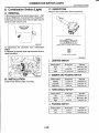
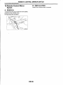
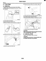
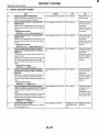
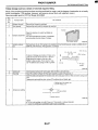
2. Refrigerant Pressure with Manifold Gauge Set
A: OPERATION
1) Place the vehicle in the shade and draftless condition.
2) Connect the manifold gauge set.
3) Open the front windows and close all doors.
4) Open the hood.
5) Increase the engine to 1,500 rpm.
6) Turn ON the A/C switch.
7) Turn the temperature control switch to MAX COOL.
8) Put in RECIRC position.
9) Turn the blower control switch to HI.
10) Read the gauge.
Standard:
Low pressure: 127 196 kPa (1.3 - 2.0 kg/cn?, 18 - 28 psi)
High pressure: 1,471 - 1,667 kPa (15 - 17 kg/cn?, 213 - 242 psi)
Ambient temperature: 30 - 35 OC (86 95 OF)
-
-
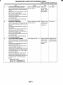
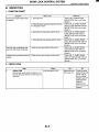
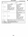
B: INSPECTION
-.
r
Svmntnm
I
I
I
High-pressureside is unusually high.
High-pressureside is unusually low.
Low-pressure side is unusually high.
Low-pressure side is unusually low.
Probable cause
Defective condenser fan motor
Clogged condenser fan
Too much refrigerant
Air inside the system
Defective receiver dryer
Defective compressor
Not enough refrigerant
Clogged expansion valve
Expansion valve frozen temporarily by
moisture
Defective compressor
Defective expansion valve
Too much refrigerant
Not enough refrigerant
Clogged expansion valve
Expansion valve frozen temporarily by
moisture
Saturated receiver dryer
AC-15
Replace the fan motor.
Clean the condenser fin.
Discharge refrigerant.
Replace the receiver dryer.
Replace the compressor.
Check for leaks.
Replace the expansion valve.
Replace the compressor.
Replace the expansion valve.
Discharge refigerant.
Check for leaks.
Replace the expansion valve
Replace the receiver dryer.
I
REFRIGERANT RECOVERY PROCEDURE
HVAC SYSTEM (HEATER, VENTILATOR AND N C )
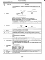
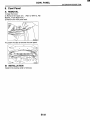
3. Refrigerant Recovery Procedure
A: OPERATION
CAUTION:
During operation, be sure to wear safety goggles and protective gloves.
Connect the refrigerant recovery system with
the manifold gauge set to discharge the refrigerant from the A/C system and reuse it.
When reusing the discharged refrigerant,
keep service cans on hand. Because the discharge rate with the recovery system is approx.
90%, service cans are necessary to charge the
refrigerant.
Follow the detailed operation procedure described in the operation manual attached to the
refrigerant recovery system.
1) Perform the compressor oil return operation.cRef. to AC-21, OPERATION, Compressor
"Oi I.>
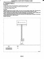
2) Stop the engine.
3) Close the valves on the low-/high-pressuresides
of the manifold gauge set.
Low-pressure gauge
(Compound pressure gauge)
Close
I
Close
G4M0585
4) Install the low-/high-pressure hoses to the service ports on the low-/high-pressure sides of the
vehicle respectively.
Low-pressure gauge
(Compound pressure gauge)
5) Connect the center hose to the refrigerant recovery system.
6) Follow the operation manual to activate the refrigerant recovery system.
AC-16
REFRIGERANT CHARGING PROCEDURE
HVAC SYSTEM (HEATER, VENTILATOR AND N C )
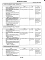
4. Refrigerant Charging Procedure
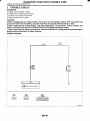
4) Carefully open the valves on the low-/high-pressure sides to activate the vacuum pump.
I
A: OPERATION
CAUTION:
During operation, be sure to wear safety goggles and protective gloves.
Before charging the refrigerant, evacuate the
system to remove small amounts of moisture
remaining in the system.
The moisture in the system can be completely
evacuated only under the minimum vacuum
level. The minimum vacuum level affects the
temperature in the system.
The list below shows the vacuum values necessary to boil water in various temperature. In
addition, the vacuum levels indicated on the
gauge are approx. 3.3 kPa (25 mmHg, 0.98 inHg)
lower than those measured at 304.8 m (1,000 ft)
above sea level.
Low-pressure gauge
(Compound pressure
gauge)
High-pressure gauge
Slowly
Slowly
open
G o p e n
4M0597
5) After the low-pressure gauge reaches 100.0 kPa
(750 mmHg, 29.5 inHg) or higher, evacuate the
system for approx. 15 minutes.
-.
I
I
I
I
I
Vacuum level required to boil water (at sea level)
TemDerature
I
Vacuum
I
1.7"C (35°F)
1I 100.9 kPa (757 "Ha. -. 29.8 inHal
7.2"C (45°F)
I 100.5 kPa (754 mmHa 29.7 inHa)
12.8"C (55°F) I
99.8 kPa (749 mmHa 29.5 inHq)
18.3"C (65°F)
99.2 kPa (744 mmHg, 29.3 inHg)
98.5 kPa (739 mmHg, 29.1 inHg)
23.9"C (75°F) 1
29.4"C (85°F)
97.2 kPa (729 mmHg, 28.7 inHg)
95.8 kPa (719 mmHg, 28.3 inHg)
35°C (95°F)
"I
I
I
I
I
I
I
I
G4M0598
6) After 15 minutes of evacuation, if the reading
shows 100.0 kPa (750 mmHg, 29.5 inHg) or higher,
close the valves on the both sides to stop the vacuum pump.
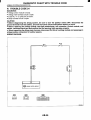
1) Close the valves on low-/high-pressure sides of
the manifold gauge.
Low-pressure gauge
(Compound pressure
gauge)
High-pressure gauge
Low-pressure gauge
(Compound pressure gauge)
Close
Close
Close
Close
Vacuu
Turn OFF
u l d u
G4M0599
7) Note the low-pressure gauge reading.
G4M0596
2) Install the low-/high-pressure hoses to the corresponding service ports on the vehicle respectively.
3) Connect the center hose of the manifold gauge
set with the vacuum pump.
AC-17
I
REFRIGERANT CHARGING PROCEDURE
HVAC SYSTEM (HEATER, VENTILATOR AND A/C)
8) Leave it at least 5 minutes, and then check the
low-pressure gauge reading for any changes.
When a gauge indicator shows near to zero point,
this is a sign of leakage. Check pipe connector
points, repair them, make sure there is no leakage
by air bleeding.
9) Following the can tap operation manual instructions, install it to the refrigerant can.
I
15) Carefully open the high-pressure valve with the
engine stopping.
CAUTION:
Do not open the low-pressure valve.
Low-pressure gauge
(Compound pressure
6
High-pressure
Tap valve
Center
manifold
hose
Close
\
G4M0601
G4M0980
10) Disconnect the center manifold hose from the
,.vacuum pump, and connect the hose to the tap
valve.
11) When a 13.6 kg (30 Ib) refrigerant container is
used, measure the refrigerant amount in use using
a weight scale.
Refrigerant
container
(HFC-I34a)
Weight
scale
c
CAUTION:
Never run the engine during charging from the
high-pressure side.
16) Close the high-pressure valve when the lowpressure gauge reaches 98 kPa (1 kg/cm2, 14 psi).
Using a leak tester, check the system for leaks.
If any leakage is found after the refrigerant recovery is completed, repair the applicable area.
17) After confirming that there are no leaks with the
leak test, charge the required amount of refrigerant.
CAUTION:
Never run the engine during charging from the
high-pressure side.
18) Close the high-pressure valve when;
the readings of low- / high-pressure gauges become almost equal, after the charging speed is reduced,
the HFC-134a source becomes empty, or
the system is filled with the gas.
G4M0981
12) Confirm that all the 3 hoses are tightly connected to the manifold gauge set.
Low-pressure gauge
(Compound pressure gauge)
Close
Close
G4M060E
I
G4M0603
I
13) Open the valve on the HFC-134a source.
14) Loosen the center hose connection on the
manifold gauge set (if applicable, press a purge
valve on the manifold gauge set) only for a couple
of seconds to allow the air in the center hose to escape by the refrigerant.
AC-18
REFRIGERANT CHARGING PROCEDURE
HVAC SYSTEM (HEATER, VENTILATOR AND N C )
19) If the HFC-134a source is empty, close the
high-pressure valve, close the valve on the can tap,
and replace the HFC-134a source with a new one
to restart the operation.
Low-pressure gauge
(Compound pressure
27) Disconnect the hose from the service port, and
install the service port cap.
High-pressure gauge
I
G4M0606
20) Confirm that both the low- / high-pressure
valves can be closed. Start the engine with the A/C
switch OFF.
21) Quickly repeat ON-OFF cycles a few times to
prevent initial compressor damage.
22).Set up the vehicle to the following status:
A/C switch ON
Engine running at 1,500 rpm
Blower speed setting to “HI”
Temperature setting to “MAX COOL”
Air inlet setting to “RECIRC”
Windows open
23) While reading the low-pressure gauge, carefully open the low-pressure valve with the refrigerant
source connected and the service hose purged.
CAUTION:
Never open the high-pressure valve with the engine is running.
G4M0608
24) Adjust the refrigerant flow to maintain the pressure on the low-pressure side at 276 kPa (2.81 kg/
cm2,40 psi) max.
25) After the system is fully charged, close the lowpressure valve.
26) Close the valve on the refrigerant source.
I
Refrigerant
HFC-134a
Refrigerant amount
Minimum
0.6 kg (1.3 Ib)
I
Maximum
0.7 kg (1.5 Ib)
AC-19
a
I
REFRIGERANT LEAK CHECK
HVAC SYSTEM (HEATER, VENTILATOR AND A/C)
5. Refrigerant Leak Check
A: INSPECTION
1) Operate the A/C system for approx. 10 minutes,
and confirm that the high-side pressure shows at
least 690 kPa (7.03 kg/cm2, 100 psi). Then stop the
engine to start the leak test.
2) Starting from the connection between the highpressure tube and evaporator, check the system
for leaks along the high-pressure side through the
compressor. The following items must be checked
thoroughly.
3) Check the joint and seam between the pressure
switch (dual switch) and receiver dryer.
4) Check the connections between the condenser
and tubes, and welded joints on the condenser.
The leak tester may detect the oil on the condenser
fins as a leak.
5) Check the joint between the compressor and
hoses.
c
6). Check the machined area of compressor and
other joints on the compressor.
7) Check the thermal limiter (if equipped) on the
compressor housing.
8) Check the compressor shaft seal at the area
near the center of compressor clutch pulley.
Some shaft seals show a slight amount of leakage
about 28 g (1.O oz) per year. This is not a problem.
9) Starting from the connection between the lowpressure tube and evaporator, check the system
for leakage along the high-pressure side through
the compressor. The following items must be
checked thoroughly.
Connection between the tube and tube fitting
Connection between 2 parts
Connection between the tube and nut
IO) Visually check the rubber area of the flexible
hose for cracks.
Check the entire length of the flexible hose, especially the connection with the metal hose end.
CAUTION:
Carefully check the external surface of hoses
and tubes at approx. 25 mm (0.98 in) per second.
Flexible hose
G4M0617
11) Disconnect the drain hose from the evaporator
case, and check the hose end for at least 10 seconds.
After the test is finished, reconnect the drain hose.
12) Turn the ignition key to ON position, and run the
blower at high speed for 1 minute. Stop the blower
to check the ventilation grille on the instrument panel. While moving the tester closer to the grille, run
the blower for 1 or 2 seconds, then stop it. Check
the grille at that point for at least 10 seconds.
13) Check the valve in the service port.
14) Visually check the rubber seal in the service
port cap.
AC-20
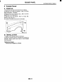
COMPRESSOR OIL
HVAC SYSTEM (HEATER. VENTILATOR AND A/Cl
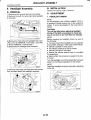
6. Compressor Oil
B: REPLACEMENT
A: OPERATION
NOTE:
If a component is replaced, add an appropriate
amount of compressor oil.
When replacing the compressor, the new compressor will already have the specified amount of
oil in it. Install the new compressor after removing
the same amount of oil that is remaining in the compressor removed.
NOTE:
Before making repairs, conduct the oil return operation to return the compressor oil in circulation with
the refrigerant to the compressor.
1) Increase the engine to 1,500 rpm.
2) Turn ON the A/C switch.
3) Turn the temperature control switch to MAX
COOL.
4) Put in RECIRC position.
5) Turn the blower control switch to HI.
6) Leave in this condition for 10 minutes.
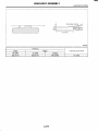
Amount of oil replenishment
I
114 m 8 (3.9 US fl 02,4.0 Imp fl 02) I
7 m 8 (0.24 US fl 02, 0.25 Imp fl 02) I
I 1 m 8 (0.03 US fl 02. 0.04 ImD fl 02) I
I Replacement parts I
I Evaporator
I
I
I Condenser
I Hose
AC-21
BLOWER MOTOR UNIT ASSEMBLY
HVAC SYSTEM (HEATER, VENTILATOR AND A/C)
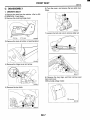
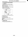
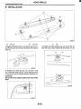
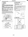
7. Blower Motor Unit Assembly
B: INSTALLATION
Install in the reverse order of removal.
A: REMOVAL
1) Disconnect the ground terminal from battery.
2) Remove the glove box. <Ref. to EI-39, REMOVAL, Glove Box.>
3) Loosen the nut to remove support beam stay.
C: INSPECTION
Connect the motor connector terminal 1 from the
battery to the positive (+) lead and terminal 2 to the
negative (-) lead. Make sure the motor runs
smoothly.
I
404
4) Disconnect the blower motor connector.
--
5 ) Disconnect the blower resistor connector
6) Loosen the bolt and nut to remove blower motor
unit assembly.
HV0013
AC-22
BLOWER RESISTOR
HVAC SYSTEM (HEATER, VENTILATOR AND N C )
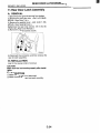
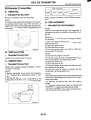
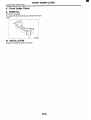
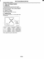
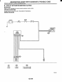
8. Blower Resistor
A: REMOVAL
1) Remove the glove box. <Ref. to El-39, REMOVAL, Glove Box.>
2) Disconnect the blower resistor connector.
3) Loosen two screws to remove the blower resistor.
B: INSTALLATION
IKstall in the reverse order of removal.
C: INSPECTION
HVO0.57
I
I
I
3 and 1
3 and 2
3 and 4
I
I
Approx. 2.70 0
I
Approx. 1.43 0
Approx. 0.51 0
I
I
I
If NG, replace the blower resistor
AC-23
HEATER CORE
HVAC SYSTEM (HEATER, VENTILATOR AND N C )
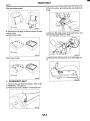
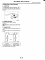
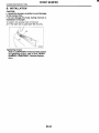
9. Heater Core
A: REMOVAL
1) Remove the heater and cooling unit. <Ref. to
AC-28, REMOVAL, Heater and Cooling Unit.>
2) Loosen the screws to remove heater core cover.
HVOOOl
3) Remove the heater core.
--
HV0002
B: INSTALLATION
Install in the reverse order of removal.
AC-24
CONTROL UNIT
HVAC SYSTEM (HEATER, VENTILATOR AND NC)
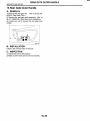
1O.Control Unit
A: REMOVAL
1) Disconnect the ground terminal from battery.
5 ) Remove the center console panel.
=J
1
r Clip
2) Remove the glove box. <Ref. to El-39, REMOVAL, Glove Box.>
3) Remove the lower panel. <Ref. to El-42, Instrument Panel Assembly.>
4) Remove the control wires.
7) Pull out the control unit and disconnect connectors.
x
B: INSTALLATION
Install in the reverse order of removal.
-1-
BOO1 1 i
6) Remove four screws.
AC-25
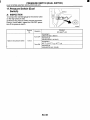
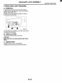
COMPRESSOR
HVAC SYSTEM (HEATER, VENTILATOR AND NC)
7) Remove the low-pressure hose and high-pressure hose.
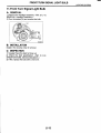
11.Compressor
A: INSPECTION
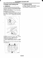
1. MAGNETIC CLUTCH CLEARANCE
1) Check the clearance of the entire circumference
around the drive plate and pulley.
Standard:
0.45-M.15 mm (0.0177-M.0059 in)
2. MAGNETIC CLUTCH OPERATION
1) Disconnect the compressor connector.
2) Connect the battery positive terminal to the No.3
terminal of the compressor connector.
Ground the negative terminal to the body.
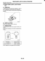
8) Disconnect the compressor harness from body
harness.
9) Loosen the bolts to remove compressor bracket.
84M2407
3) Make sure the magnet clutch engages.
If NG, replace the compressor.
10) Remove the bolts and then separate compressor and bracket.
B: REMOVAL
1) Perform the compressor oil return operation.
<Ref. to AC-21, OPERATION, Compressor Oil.>
2) Turn A/C switch OFF and stop the engine.
3) Using refrigerant recovery system, discharge refrigerant. <Ref. to AC-16, OPERATION, Refrigerant Recovery Procedure.>
4) Disconnect the ground terminal from battery.
5) Remove the V-belt. <Ref. to ME(S0HC)-43, REMOVAL, V-belt.> or <Ref. to ME(D0HC TURBO)44, REMOVAL, V-belt.>
6) Remove the generator. <Ref. to SC-13, REMOVAL, Generator.>
HVOOI 1
C: INSTALLATION
1) Install in the reverse order of removal.
2) Replace the O-rings on low-/high-pressure hoses with new ones, then apply compressor oil.
3) When replacing the compressor, adjust amount
of compressor oil. <Ref. to AC-21, OPERATION,
Compressor Oil.>
4) Charge refrigerant. <Ref. to AC-17, OPERATION, Refrigerant Charging Procedure.>
AC-26
I
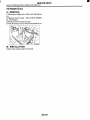
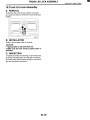
CONDENSER
HVAC SYSTEM (HEATER, VENTILATOR AND N C )
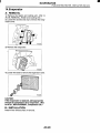
12.Condenser
B: INSTALLATION
A: REMOVAL
1) Using the refrigerant recovery system, discharge
refrigerant. <Ref. to AC-16, OPERATION, Refrigerant Recovery Procedure.>
2) Disconnect the ground terminal from battery.
3) Disconnect the pressure hose and pipe from
condenser.
1) Install in the reverse order of removal
CAUTION:
Replace the O-rings on hoses or pipes with new
ones, and then apply compressor oil. Confirm
that lower guide of condenser (A) has been fitted into holes on radiator panel.
I
Y
B4M1822A
I
2) Charge refrigerant. <Ref. to AC-17, OPERATION, Refrigerant Charging Procedure.>
4rRemove the radiator bracket (A).
C: INSPECTION
1
1) Confirm that no dust or insects are found on the
condenser fins. Air-blow or flush fins with water as
needed.
2) Confirm that no oil leaks from condenser. If a failure is found, replace the condenser with a new one.
5 ) Remove two bolts. While lifting condenser, pull it
out through space between the radiator and the radiator panel.
CAUTION:
Be careful not t o damage the condenser fins. If
a damaged fin is found, repair it using a thin
screwdriver.
If the condenser is replaced, add appropriate
amount of compressor oil t o the compressor.
<Ref. t o AC-21, REPLACEMENT, Compressor
Oil.>
AC-27
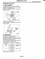
HEATER AND COOLING UNIT
HVAC SYSTEM (HEATER, VENTILATOR AND N C )
B: INSTALLATION
13.Heater and Cooling Unit
A: REMOVAL
1) Disconnect the ground terminal from battery.
2) Using the refrigerant recovery system, discharge
refrigerant. <Ref. to AC-16, OPERATION, Refrigerant Recovery Procedure.>
3) Drain LLC from the radiator. <Ref. to CO-25, REPLACEMENT, Engine Coolant.>
4) Remove the bolts securing expansion valve and
pipe in engine compartment. Release the heater
hose clamps in engine compartment to remove the
hoses.
1) Install in the reverse order of removal.
2) Charge refrigerant. <Ref. to AC-17, OPERATION, Refrigerant Charging Procedure.>
C.
HVOOE
5) Remove the instrument panel. <Ref. to El-42,
REMOVAL, Instrument Panel Assembly.>
6) Remove the support beam.
7) Remove the blower motor unit assembly. <Ref.
to AC-22, REMOVAL, Blower Motor Unit Assembly.>
8) Loosen the bolt and nuts to remove the heater
and cooling unit.
AC-28
I
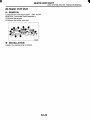
EVAPORATOR
HVAC SYSTEM (HEATER, VENTILATOR AND N C )
14.Evaporator
A: REMOVAL
1) Remove the heater and cooling unit. <Ref. to
AC-28, REMOVAL, Heater and Cooling Unit.>
2) Loosen the screws and clip to remove the evaporator cover.
HV0024
3) Remove the evaporator.
4) Loosen two bolts to remove the expansion valve.
HV0026
CAUTION:
If the evaporator is replaced, add appropriate
amount of compressor oil to evaporator. <Ref.
to AC-21, REPLACEMENT, Compressor Oil.>
B: INSTALLATION
Install in the reverse order of removal.
AC-29
HOSE AND TUBE
HVAC SYSTEM (HEATER, VENTILATOR AND N C )
13) Remove the high-pressure tube from the vehicle.
15.Hose and Tube
A: REMOVAL
CAUTION:
When disconnecting/connecting hoses, do
not apply excessive force to them. Confirm that
no torsion and excessive tension exists after
installing.
Seal the disconnected hose with a plug or vinyl tape to prevent contamination from entering.
1) Disconnect the ground terminal from battery.
2) Using the refrigerant recovery system, discharge
refrigerant. <Ref. to AC-16, OPERATION, Refrigerant Recovery Procedure.>
3) Remove the evaporator unit mounting bolt (A).
4) Remove the low-pressure hose attaching bolts
(B).
5) Disconnect the low-pressure hose from evaporator
-. unit.
6) Disconnect the low-pressure hose from compressor.
7) Remove the low-pressure hose from the vehicle.
8) Remove the high-pressure hose attaching bolts
(C).
9) Disconnect the high-pressure hose from compressor.
10) Disconnect the high-pressure hose from condenser.
11) Remove the high-pressure hose from the vehicle.
12) Remove the high-pressure tube attaching bolt
0 .
B: iNSTALLATlON
CAUTION:
When disconnectingkonnecting hoses, do
not apply an excessive force to them. Confirm
that no torsion and excessive tension exists after installing.
Seal the disconnected hose with a plug or vinyl tape to prevent contamination from entering.
1) Install in the reverse order of removal.
2) Charge refrigerant. <Ref. to AC-17, OPERATION, Refrigerant Charging Procedure.>
C: INSPECTION
NOTE:
If cracking, damage, or swelling is found on a hose,
replace it with a new one.
AC-30
I
RELAY AND FUSE
HVAC SYSTEM (HEATER, VENTILATOR AND N C )
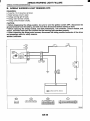
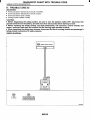
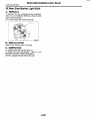
B: INSPECTION
16.Relay and Fuse
A: LOCATION
Joint box
HV006
Main fuse box
HV0022
Main Fan Relay 1
Main Fan Relay 2
Sub Fan Relay 1
Sub Fan Relay 2
A/C Relay
Main Fan Fuse
Sub Fan Fuse
N C Fuse
A
B
C
(3) - (4): Continuity exists.
(1) - (2): No continuity
While applying battery voltage to the cable between (3) and (4),
check continuity between (1) and
(2).
If no continuity exists, replace the relay with a new
one.
G
H
AC-31
PRESSURE SWITCH (DUAL SWITCH)
HVAC SYSTEM (HEATER, VENTILATOR AND NC)
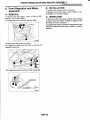
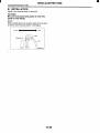
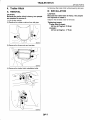
17.Pressure Switch (Dual
Switch)
A: INSPECTION
1) Connect the manifold gauge to the service valve
on the high-pressure side.
2) Remove the pressure switch harness connector.
Using a circuit tester, inspect the ON-OFF operation of the pressure switch.
1
Terminal
No.
1
Standard
kPa (kg/cm2, psi)
Operation
Increasing to
2,800flOO(29fl14O6k1
5)
Turns OFF.
Decreasingto
278+29 (2.83k0.3,
40.3M.2)
High and low pressure switch
1 and2
Turns ON.
I
Decreasing to
2,20M200(22.4+2,31%29)
AC-32
AIR VENT GRILLE
HVAC SYSTEM (HEATER, VENTILATOR AND NC)
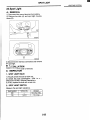
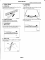
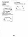
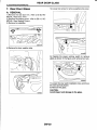
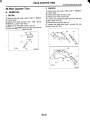
18.Air Vent Grille
A: REMOVAL
1. CENTER GRILLE
1) Disconnect the ground terminal from battery.
2) Remove the center console panel (A).
3) Loosen two screws to remove the center air vent
grille (B).
2:-SIDE GRILLE
1) Disconnect the ground terminal from battery.
2) Remove the heater vent duct. <Ref. to AC-35,
REMOVAL, Heater Vent Duct.>
3) Loosen the screws to remove the side air vent
grille.
B: INSTALLATION
Install in the reverse order of removal.
C: INSPECTION
The direction and amount of air should be adjusted
smoothly.
The adjustment should be kept in each position.
AC-33
I
HEATER DUCT
HVAC SYSTEM (HEATER, VENTILATOR AND A/C)
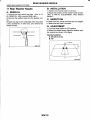
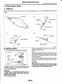
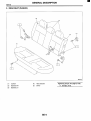
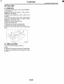
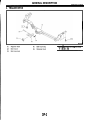
19.Heater Duct
A: REMOVAL
1) Remove the heater unit. <Ref. to AC-28, Removal.>
2) Remove the front seat. <Ref. to SE-6, REMOVAL, Front Seat.>
3) Remove the front side sill cover.
4) Pull off the floor mat to remove the heater duct.
IB: INSTALLATION
Install in the reverse order of removal.
AC-34
HEATERVENTDUCT
HVAC SYSTEM (HEATER, VENTILATOR AND N C )
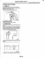
20.Heater Vent Duct
A: REMOVAL
1) Remove the instrument panel. <Ref. to El-42,
REMOVAL, Instrument Panel Assembly.>
2) Remove the screws.
3) Remove the heater vent duct.
I
HV0064
I
B: INSTALLATION
Install in the reverse order of removal.
AC-35
c3
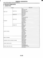
GENERAL DIAGNOSTICS
HVAC SYSTEM (HEATER. VENTILATOR AND A/C)
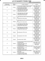
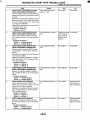
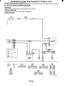
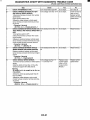
21 .General Diagnostics
A: INSPECTION
I Fuse
Doesn't move.
Blower motor
I
Blower motor relay
Blower motor
Blower motor resistor
Blower switch
Stranqe noise.
I Wire harness
1 Blower motor
Doesn't move.
Refrigerant
Fuse
Air conditioning relay
Maanet clutch
(Comoressor
~
I Pressure switch
I A/C switch
I Refrigerant
I V-Belt
Magnet clutch
Compressor
Pressure switch
m w i t c h
I Blower switch
I Wire harness
I Heater duct
~
Temperature of air from vents does not change.
Unable to switch blow vents.
Unable to switch suction vents.
I
I
I
Blower switch
Wire harness
V-Belt
Magnet clutch
Compressor
Strange noise
Warm air not emitted.
I
I
Heater vent duct
Enaine coolant
Blower switch
~
I
I
I
I
I
~~~
I
Heater core
Engine coolant
Mode actuator
Wire harness
Mode actuator
Air flow switch
I
Wire harness
Air inlet select switch
FRESH/RECIRC actuator
Wire harness
I
I
I
AC-36
I
AIRBAG SYSTEM
A5
Page
1.
2.
3.
4.
5.
6.
7.
8.
9.
10.
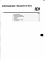
General Description ....................................................................................
Airbag Connector ........................................................................................
Inspection Locations After a Collision .......................................................
Driver's Airbag Module..............................................................................
Passenger'sAirbag Module ......................................................................
Side Airbag Module...................................................................................
Airbag Control Module ..............................................................................
Side Airbag Sensor ...................................................................................
Roll Connector ..........................................................................................
Front Sub Sensor ......................................................................................
2
8
10
12
13
14
15
16
17
18
m
I
GENERAL DESCRIPTION
AI RBAG SYSTEM
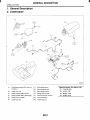
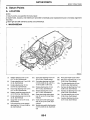
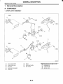
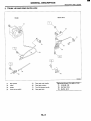
1. General Description
A: COMPONENT
\
RE0031
(2) TORX@bolt T30
(8)
(9)
Side airbag sensor
Side airbag harness
Side airbag module
(3)
(4)
(5)
(10)
(1 1)
(12)
Airbag main harness
Front sub sensor harness
Front sub sensor
(13)
TORX@bolt T30
(1)
Combination switch ASSY with roll
connector
Airbag module ASSY (Driver)
Airbag module ASSY (Passenger)
Airbag control module
(6) T O R P bolt T40
(7)
AB-2
Tightening torque: N.m (kgf-m, ft-lb)
T1: 7.4 (0.75, 5.4)
T2: l O ( 1 . 0 , 7.2)
T3: 20 (2.0, 14.5)
T4: 25 (2.5, 18.1)
GENERAL DESCRIPTION
AIRBAG SYSTEM
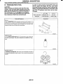
When checking, use a test harness. Do not directly apply the tester probe to any connector terminal of the airbag.
B: CAUTION
When servicing a vehicle, be sure to turn the ignition switch OFF, disconnect the ground terminal
from battery, and wait for more than 20 seconds
before starting work.
The airbag system is fitted with a backup power
source. If the airbag system is serviced within 20
seconds after the ground terminal is disconnected,
it may inflate.
NO GOOD
GOOD
G5M0293
NO GOOD
\
1
G5M0292
c-If the sensors, airbag module, airbag control
module, pretensioner and harness are deformed or
damaged, replace them with new genuine parts.
I
I
I
I
NO GOOD
GOOD
Test harness
G5M0291
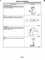
Do not use the airbag or pretensioner parts from
other vehicles. Always replace the defective parts
with new parts.
Never re-use a deployed airbag or pretensioner.
When checking the system, be sure to use a digital circuit tester.
Use of an analog circuit tester may cause the airbag to activate erroneously.
G5M0294
Do not check continuity of the driver, passenger,
side airbag modules and pretensioner.
I
NO GOOD
AB-3
G5M0302
I
GENERAL DESCRIPTION
AIRBAG SYSTEM
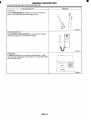
Do not allow water or oil to come in contact with
the connector terminals. Do not touch the connector terminals.
A
\
Install the wire harness securely with the specified clips to avoid interference or tangled up with
other parts.
NO GOOD
G5M0298
G5M0297
The airbag module (driver, passenger and side)
and pretensioner must not be disassembled.
NO GOOD
v
~’
When painting or performing sheet metal work
on the front part of the vehicle, including the front
wheel apron, front fender, and front side frame, remove the front sub sensors and wire harness of the
airbag system.
When painting or performing sheet metal work
on the side of the vehicle, including the side sill,
center pillar, and front and rear doors, remove the
side airbag sensors and wire harness of the airbag
system.
G5M0299
If any damage, opening, or rust is found on the
airbag system wire harness, do not attempt to repair using soldering equipment. Be sure to replace
the faulty harness with a new genuine part.
\\
NO GOOD
G5M0296
AB-4
NO GOOD
G5M0310
GENERAL DESCRIPTION
Do not drop the airbag modulator parts, subject
them to high temperature over 93°C (199"F), or let
water, oil, or grease get on them; otherwise, the internal parts may be damaged and reliability greatly
lowered.
NO GOOD
G5M0295
The removed front seat with the airbag module
must be kept at least 200 mm (8 in) away from walls
and other objects.
I
I
When storing a removed airbag module, do not
place any objects on it or pile airbag modules on
top of each other. If the airbag inflates for some reason when it is placed with its pad side facing downward or under any object, a serious accident may
result.
AB-5
AIRBAG SYSTEM
GENERAL DESCRIPTION
AIRBAG SYSTEM
Driver side
GOOD
Passenger side
NO GOOD
L
NO GOOD
G5M0604
AB-6
GENERAL DESCRIPTION
AIRBAG SYSTEM
C: PREPARATION TOOL
1. GENERAL TOOL
TORP
T ~ O
Used for removaVinstallation of drivers airbag module
T O R P T40 (Tamper resistant type)
Used for removaVinstallation of airbag control module
TOR)(@T30 (TamDer resistant m e )
Used for removal of side airbag sensor.
AB-7
I
AIRBAG CONNECTOR
AIRBAG SYSTEM
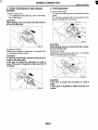
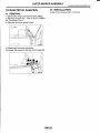
2. Airbag Connector
2. DRIVER'S AIRBAG, PASSENGER'S AIRBAG, SIDE AIRBAG
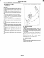
A: OPERATION
1. POWER SUPPLY
1) How to disconnect:
(1) Move the slide lock (A) in the direction of the
arrow.
(2) Pull the female connector in the direction of
the arrow with slide lock (A) moved.
1) How to disconnect:
(1) Push the lock arm (A).
(2) With the lock arm (A) pushed in, move the
slide lock (6)in the direction of the arrow.
(3) With the slide lock (6)pulled, remove the
lock arm (A) to its original position, and then pull
in the direction of the arrow and separate the
connector.
RE0012
CAUTION:
When pulling, be sure to hold onto the connector and not the wire.
2) How to connect:
Holding the connector (A), and push it in carefully
until a connecting sound is heard.
lY
CAUTION:
When pulling, be sure to hold onto the connector and not the wire.
1
B5M1154
/
RE0013
I
CAUTION:
Be sure to insert the connector in until it locks.
Then pull on it gently to make sure that it is
locked.
2) How to connect:
Holding the connector, and push it in carefully until
a connecting sound is heard.
CAUTION:
Be sure to insert the connector in until it locks.
Then pull on it gently to make sure that it is
locked.
AB-8
I
AIRBAG CONNECTOR
AIRBAG SYSTEM
4. PRETENSIONER
3. FRONT SUB-SENSOR, SIDE AIRBAG
SENSOR
1) How to disconnect:
(1) Holding the outer part (A), pull it in the direction of the arrow.
CAUTION:
When pulling, be sure to hold onto the connector and not the wire.
2) How to connect:
Holding the connector, and push it in carefully until
a connecting sound is heard.
CA UTI0N:
Outer (A) moves back, and so do not put your
hand on the outer part.
Be sure to insert the connector in until it
locks. Then pull on it gently to make sure that it
is locked.
1) How to disconnect:
(1) Move the slide lock (A) in the direction of the
arrow.
(2) Pull the connector (B)in the direction of the
arrow with slide lock (A) moved.
CAUTION:
When pulling, be sure to hold onto the connector and not the wire.
2) How to connect:
Holding the connector (A), and push it in carefully
until a connecting sound is heard.
CAUTION:
Be sure to insert the connector in until it
locks.
Then pull on it gently to make sure that it is
locked.
AB-9
I
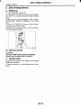
INSPECTION LOCATIONS AFTER A COLLISION
AIRBAG SYSTEM
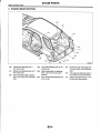
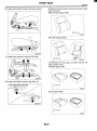
3. Inspection Locations After a
Collision
3. AIRBAG MODULE (SIDE)
If the vehicle is involved in a collision on any side,
even if it is a slight collision, be sure to check the
following system parts.
Check for the following, and replace damaged
parts with new parts.
Front seat is damaged or deformed.
Harness and/or connector is cracked, deformed
or open.
Lead wire is exposed.
1. AIRBAG MODULE (DRIVER)
4. AIRBAG CONTROL MODULE
1) Check for the following, and replace the damaged parts with new parts.
Airbag module is cracked or deformed.
Harness and/or connector is cracked, deformed
or open. Lead wire is exposed.
The module surface is fouled with grease, oil,
water or cleaning solvent.
2) When installing a new driver's airbag module,
check the following. If necessary, install a new airbag module and steering wheel.
The steering wheel is in the way, making it diffip ~ ltot install the airbag module.
The clearance between the driver's airbag module and steering wheel is not constant.
When steering wheel deformation in axial and radial directions exceed limits.
Check for the following, and replace the damaged
parts with new parts.
Control module is cracked or deformed.
Mounting bracket is cracked or deformed.
Connector is scratched or deformed.
Airbag is deployed.
Side airbag is deployed.
A: INSPECTION
5. FRONT SUB SENSOR
If the front section of vehicle as shown in the figure
is damaged:
Specifications:
Axial direction play A
Less than 6 mm (0.24 in)
Radial direction play L
Less than 17 mm (0.67 in)
I
I
Check for the following, and replace the damaged
parts with new parts.
Front sub sensor is cracked or deformed.
Mounting bracket is cracked or deformed.
Connector is scratched or cracked.
Airbag is deployed.
I
I
2. AIRBAG MODULE (PASSENGER)
Check for the following, and replace damaged
parts with new parts.
Airbag module is cracked or deformed.
Harness and/or connector is cracked, deformed
or open. Lead wire is exposed.
Mounting bracket is cracked or deformed.
6. FRONT SUB SENSOR HARNESS
Check for the following, and replace the damaged
parts with new parts.
Harness is open, lead wire is exposed, and corrugated tube is noticeably cracked.
Connector is scratched or cracked.
AB-I 0
INSPECTION LOCATIONS AFTER A COLLISION
AIRBAG SYSTEM
7. SIDE AIRBAG SENSOR
8. SIDE AIRBAG SENSOR HARNESS
If the side section of vehicle as shown in the figure
is damaged:
Check for the following, and replace the damaged
parts with new parts.
Harness is open, lead wire is exposed, and corrugated tube is noticeably cracked.
Connector is scratched or cracked.
9. MAIN HARNESS
Check for the following, and replace the damaged
parts with new parts.
Harness is open, lead wire is exposed, and corrugated tube is noticeably cracked.
Connector is scratched or cracked.
05M0514
10.ROLL CONNECTOR
Check for the following, and replace the damaged
parts with new parts.
Combination switch or steering roll connector is
cracked or deformed.
Check for the following, and replace the damaged
parts with new parts.
Side airbag sensor is cracked or deformed.
Mounting bracket is cracked or deformed.
Connector is scratched or cracked.
Side airbag is deployed. (operating side)
r.
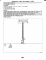
11.STEERING SHAFT
Check for the following, and replace the damaged parts with new parts.
Overall length of steering column should be within specifications.
Specifications:
Overall length L
825.751.5 mm (32.5H.06 in)
L
RE0032
If necessary, replace it with new part.
AB-1 1
I
DRIVER’S AIRBAG MODULE
AIRBAG SYSTEM
D: INSPECTION
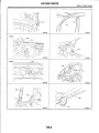
4. Driver’s Airbag Module
A: CAUTION
Refer to the “CAUTION” of General Description before handling the airbag module. <Ref. to AB-3,
CAUTION, General Description.>
Check for the following, and replace the damaged
parts with new parts.
Airbag module, harness, connector, and mounting bracket are damaged.
B: REMOVAL
1) Position the front wheels straight ahead. (After
moving a vehicle more than 5 m (16 ft) with front
wheels positioned straight ahead, make sure that
the vehicle moves straight ahead).
2) Turn the ignition switch OFF.
3) Disconnect the ground terminal from battery,
and wait for at least 20 seconds before starting
work.
4) Using TORX@BIT T30, remove the two TOFIX@
bolts on the side of steering wheel.
H5M0662A
5) Disconnect the airbag connector on the back of
airbag module, and then remove the airbag module.
6) Refer to the “CAUTION” for handling of a removed airbag module. <Ref. to AB-3, CAUTION,
General Description.>
C: INSTALLATION
1) Install in the reverse order of removal.
CAUTION:
Do not allow harness and connectors to interfere or get tangled up with other parts.
AB-I 2
PASSENGER’S AIRBAG MODULE
AIRBAG SYSTEM
5. Passenger’s Airbag Module
A: CAUTION
Refer to the “CAUTION” of General Description before handling the airbag module. <Ref. to AB-3,
CAUTION, General Description.>
B: REMOVAL
1) Turn the ignition switch OFF.
2) Disconnect the ground terminal from battery,
and wait for at least 20 seconds before starting
work.
3) Remove the glove box. <Ref. to El-39, REMOVAL, Glove Box.>
4) Detach the airbag connector from the support
beam bracket, and then disconnect the airbag connector.
5) Remove the three bolts, and then carefully remove the airbag module.
6) Refer to the “CAUTION” for handling of a removed airbag module. <Ref. to AB-3, CAUTION,
General Description.>
C: INSTALLATION
Install in the reverse order of removal.
CAUTION:
Do not allow harness and connectors to interfere or get tangled up with other parts.
D: INSPECTION
Check for the following, and replace the damaged
parts with new parts.
Airbag module, harness, connector, and mounting bracket are damaged.
AB-I 3
I
SIDE AIRBAG MODULE
AIRBAG SYSTEM
6. Side Airbag Module
A: CAUTION
Refer to the “CAUTION” of General Description before handling the airbag module. <Ref. to AB-3,
CAUTION, General Description.>
B: REMOVAL
CAUTION:
The side airbag module cannot be detached
from the front seat assembly.
When replacing side airbag module, replace
front seat assembly.
<Ref. to SE-6, REMOVAL, Front Seat.>
C: INSTALLATION
<Ref. to SE-6, INSTALLATION, Front Seat.>
D: INSPECTION
Check for the following, and replace the damaged
parts with new parts.
-* Front seat is deformed or damaged.
Harness and/or connector is cracked, deformed
or open.
Lead wire is exposed.
AB-14
AIRBAG CONTROL MODULE
AIRBAG SYSTEM
7. Airbag Control Module
A: REMOVAL
CAUTION:
Do not disassemble the airbag control module.
If the airbag control module is deformed or if
water damage is suspected, replace the airbag
control module with a new genuine part.
Do not drop the airbag control module.
After removal, keep the airbag control module on a dry, clean surface away from moisture,
heat, and dust.
1) Turn the ignition switch OFF.
2) Disconnect the ground terminal from battery,
and wait for at least 20 seconds before starting
work.
3) Remove the console box. <Ref. to El-41, REMOVAL, Console Box.>
4) Disconnect the connector from the airbag control
module.
5 ) Using T40@ TORX bit (Tamper resistant type),
remove the four TORX@bolts.
B: INSTALLATION
CAUTION:
Use new TORX@bolts during re-assembly.
Install in the reverse order of removal.
C: INSPECTION
Check for the following, and replace the damaged
parts with new parts.
Control module, connector, and mounting bracket are damaged.
Airbag is deployed.
Side airbag is deployed.
AB-I 5
I
SIDE AIRBAG SENSOR
AIRBAG SYSTEM
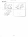
8. Side Airbag Sensor
A: REMOVAL
1) Turn the ignition switch OFF.
2) Disconnect the ground terminal from battery,
and wait for at least 20 seconds before starting
work.
3) Remove the outer belt (FRONT). <Ref. to SB-8,
OUTER BELT (FRONT), REMOVAL, Front Seat
Belt.>
4) Using T30 TORX@bit (Tamper resistant type),
remove the two TORX@bolts.
5) Detach the side airbag sensor, and then disconnect the airbag connector.
I
c-
REO018
B: INSTALLATION
CAUTION:
Use new TORX@bolts during re-assembly.
Install in the reverse order of removal.
C: INSPECTION
Check for the following, and replace the damaged
parts with new parts.
Bracket connector for side airbag sensor is damaged.
AB-I 6
ROLL CONNECTOR
AIRBAG SYSTEM
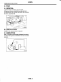
D: ADJUSTMENT
9. Roll Connector
A: REMOVAL
1) Turn the ignition switch OFF.
2) Disconnect the ground terminal from battery,
and wait for at least 20 seconds before starting
work.
3) Remove the driver’s airbag module. <Ref. to AB12, Driver’s Airbag Module.>
4) Remove the steering wheel. <Ref. to PS-19,
REMOVAL, Steering Wheel.>
5) Remove the steering column cover.
6 ) Remove the screws, and then remove the roll
connector.
1) Check that front wheels are positioned in straight
ahead direction.
2) Turn the roll connector pin (A) clockwise until it
stops.
3) Turn the roll connector pin (A) counterclockwise
approximately 2.65 turns until “A” marks are
aligned.
\
1) Install the roll connector and steering column
cover in the reverse order of removal.
2) Before installing steering wheel, be sure the direction of roll connector is adjusted with steering.
<Ref. to AB-17, ADJUSTMENT, Roll Connector.>
3) Install the steering wheel and airbag module.
C: INSPECTION
Check for the following, and replace the damaged
parts with new parts.
Combination switch and roll connector is cracked
or deformed.
AB-I 7
~~
I J
W
B: INSTALLATION
I
H5M0663B
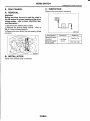
FRONT SUB SENSOR
1O.Front Sub Sensor
A: REMOVAL
1) Turn the ignition switch OFF.
2) Disconnect the ground cable from the battery,
and wait for at least 20 seconds before starting
work.
3) Remove the front bumper. <Ref. to El-23, REMOVAL, Front Bumper.>
4) Loosen the two bolts to remove sensor cover.
5) Remove the bolt, and then detach the front sub
sensor.
6) Disconnect the connector from the front sub sensor.
B: INSTALLATION
Install in the reverse order of removal.
C: INSPECTION
Check for the following, and replace the damaged
parts with new parts.
Front sub sensor, mounting bracket, and connector are damaged.
AB-I 8
AIRBAG SYSTEM (DIAGNOSTICS)
A5
1.
2.
3.
4.
5.
6.
7.
8.
9.
10.
11.
12.
13.
Page
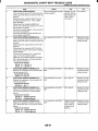
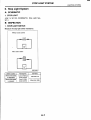
Basic Diagnostic Procedure ........................................................................ 2
Check List for Interview............................................................................... 3
General Description .................................................................................... 4
18
Electrical Components Location................................................................
A/B Control Module I/O Signal .................................................................. 20
Airbag Connector ...................................................................................... 21
Airbag Warning Light Illumination Pattern................................................. 23
Read Diagnostic Trouble Code ................................................................. 24
Inspection Mode ........................................................................................
25
Clear Memory Mode.................................................................................. 26
Airbag Warning Light Failure..................................................................... 27
32
List of Diagnostic Trouble Code ................................................................
Diagnostic Chart with Trouble Code ......................................................... 36
BASIC DIAGNOSTIC PROCEDURE
AIRBAG SYSTEM (DIAGNOSTICS)
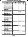
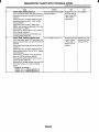
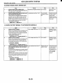
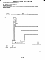
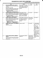
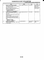
1. Basic Diagnostic Procedure
A: PROCEDURE
!
I
Step
Read Diagnostic Trouble Code.
<Ref. to AB-24, Read Diagnostic Trouble
Code.>
Read Diagnostic Trouble Code.
<Ref. to AB-24, Read Diagnostic Trouble
Code.>
Check
s the normal code being
letected?
s the trouble code being
jetected?
s the trouble code being
Perform the diagnosis.
1)Judge the possible cause from “List of Diag- Jetected?
nostic Trouble Code” <Ref. to AB-32, List of
Diagnostic Trouble Code.> .
2)lnspect using “Diagnostic Chart with Trouble
Code”. (DTC)
3)Repair the cause of the trouble.
4)Perform the clear memory mode. <Ref. to
AB-26, Clear Memory Mode.>
5)Perform the inspection mode. <Ref. to AB25, Inspection Mode.>
6)Read diagnostic trouble code.
AB-2
No
Yes
-inish the diagno- Go to step 2.
;is.
I
Go to “Airbag
Warning Light Fail,
ure”.<Ref. to AB27, Airbag Warning Light Failure.>
Perform the proce- Finish the diagnojure 1) to 5)in
sis.
30 to step 3.
CHECK LIST FOR INTERVIEW
AIRBAG SYSTEM (DIAGNOSTICS)
2. Check List for Interview
A: CHECK
Inspector's Name
Customer's Name
Date Vehicle Brought In
I
Registration No.
I
~
Odometer Reading
Date
-. - Problem Occurred
Weather
Miles
I
I
Vin No.
D Fine
D Cloudy
D Rainy
"C
I2 Level road
D Uphill
CI Starting
I2 Steering wheel turn
I2 Remains ON
r-
Ll Normal Code
AB-3
D Snowy
I
I2 Other:
(OF)
CI Downhill
0 Driving (El Constant Speed
Check DTC
I
Registration Year
D Rough road
CI Others:
D Idling
tl Acceleration
CI Other:
D Deceleration
)
D Remains OFF
D Trouble Code: (Code:
)
GENERAL DESCRIPTION
AIRBAG SYSTEM (DIAGNOSTICS)
When checking, use a test harness. Do not directly apply the tester probe to any connector terminal of the airbag.
3. General Description
A: CAUTION
When servicing a vehicle, be sure to turn the ignition switch OFF, disconnect the ground terminal
from the battery, and wait for more than 20 seconds
before starting work.
The airbag system is fitted with a backup power
source. If the airbag system is serviced within 20
seconds after the ground terminal is disconnected,
it may inflate.
NO GOOD
GOOD
G5M029:
NO GOOD
c-
\
1
G5M0292
If the sensors, airbag module, airbag control
module pretensioner and harness are deformed or
damaged, replace them with new genuine parts.
r
GOOD
NO GOOD
G5M0291
I
Do not use the airbag system and pretensioners
on other vehicles. When replacing parts, be sure to
replace them with new parts.
Never re-use a deployed airbag and pretensioner.
When checking the system, be sure to use a digital circuit tester.
Use of an analog circuit tester may cause the airbag to activate erroneously.
G5M0294
Do not check continuity of the driver, passenger,
side airbag modules and pretensioner.
NO GOOD
\
G5M0302
I
GENERAL DESCRIPTION
AIRBAG SYSTEM (DIAGNOSTICS)
Do not allow water or oil to come in contact with
the connector terminals. Do not touch the connector terminals.
Install the wire harness securely with the specified clips to avoid interference or tangled up with
other parts.
NO GOOD
I
G6M0298 I
G5M0297
The airbag module (driver, passenger, side) and
pretensioner must not be disassembled.
NO GOOD
r
When painting or performing sheet metal work
on the front part of the vehicle, including the front
wheel apron, front fender, and front side frame, remove the front sub sensors and wire harness of the
airbag system.
When painting or performing sheet metal work
on the side of the vehicle, including the side sill,
center pillar, and front and rear doors, remove the
side airbag sensors and wire harness of the airbag
system.
G5M0299
If any damage, opening or rust is found on the
airbag system wire harness, do not attempt to repair using soldering equipment. Be sure to replace
the faulty harness with a new genuine part.
\\
NO GOOD
G5M0296
AB-5
NO GOOD
G5M0310
GENERAL DESCRIPTION
AIRBAG SYSTEM (DIAGNOSTICS)
Do not drop the airbag modulator parts, subject
them to high temperature over 93°C (199"F), or let
water, oil, or grease get on them; otherwise, the internal parts may be damaged and reliability greatly
lowered.
NO GOOD
G5M029C
The removed front seat with the airbag module
must be kept at least 200 mm (8 in) away from walls
and other objects.
When storing a removed airbag module, do not
place any objects on it or pile airbag modules on
top of each other. If the airbag inflates for some reason when it is placed with its pad side facing downward or under any object, a serious accident may
result.
AB-6
GENERAL DESCRIPTION
AIRBAG SYSTEM (DIAGNOSTICS)
Driver side
GOOD
NO GOOD
A
NO GOOD
G5M0604
AB-7
GENERAL DESCRIPTION
AIRBAG SYSTEM (DIAGNOSTICS)
Do not discard undeployed airbag modules.
They could easily cause a serious accident if accidentally deployed.
B: INSPECTION
Before diagnosing, check the following items that
might be related to the engine problem:
1. BATTERY
Measure the battery voltage and specific gravity of
electrolyte.
Standard voltage: 12V
Specific gravity: Above 1.260
AB-8
GENERAL DESCRIPTION
AIRBAG SYSTEM (DIAGNOSTICS)
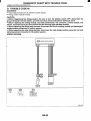
C: PREPARATION TOOL
1. SPECIAL TOOLS
TEST HARNESS M
TOOLNUMBER
98299FE020
ILLUSTRATION
I
DESCRlPTlON
I TEST HARNESS M
REMARKS
Used when measuring voltage, resistance of airbag system.
RE0033
6 5 4 3
RE0034
AB-9
GENERAL DESCRIPTION
AIRBAG SYSTEM (DIAGNOSTICS)
TEST HARNESS F
I
ILLUSTRATION
TOOLNUMBER
98299FC010
1
DESCRIPTION
I TEST HARNESS F
REMARKS
Used when measuring voltage, resistance of airbag module harnesses.
RE0035
I
RE0036
AB-I 0
GENERAL DESCRIPTION
AIRBAG SYSTEM (DIAGNOSTICS)
TEST HARNESS G
TOOL NUMBER
98299FC020
ILLUSTRATION
side airbag sensor.
RE0037
G3
1'1
l-4
&,
4 5 6 7 8
RE0038
AB-11
GENERAL DESCRIPTION
AIRBAG SYSTEM (DIAGNOSTICS)
TEST HARNESS H
DESCRIPTION
TESTHARNESSH
I
RE0039
REMARKS
Used when measuring voltage, resistance of
front sub-sensor.
I
@
RE0040
AB-I 2
GENERAL DESCRIPTION
AIRBAG SYSTEM (DIAGNOSTICS)
TEST HARNESS L
I seat belt pretensionei
RE0041
I
a
RE0042
AB-I 3
GENERAL DESCRIPTION
AIRBAG SYSTEM (DIAGNOSTICS)
TEST HARNESS 12
I
ILLUSTRATION
TOOLNUMBER
98299FC041
I
DESCRIPTION
1
REMARKS
I TEST HARNESS 12 I Used when measuring voltage, resistance of air-
REO045
r5
I
II
It
I
1i3 I
I
I
1
1
a
RE0046
GENERAL DESCRIPTION
AIRBAG SYSTEM (DIAGNOSTICS)
AIRBAG RESISTOR
ILLUSTRATION
TOOL NUMBER
98299PA040
RE0047
DESCRIPTION
REMARKS
AIRBAG RESISTOR Used in replacement of airbag module which
resistance value is same as airbag module.
I
RE0048
AB-16
a
GENERAL DESCRIPTION
AIRBAG SYSTEM (DIAGNOSTICS)
ELECTRICAL COMPONENTS LOCATION
AIRBAG SYSTEM (DIAGNOSTICS)
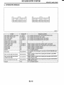
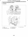
4. Electrical Components Location
A: LOCATION
*@-*@-
RE0049
r
Male connector
AB-1 8
ELECTRICAL COMPONENTS LOCATION
AI RBAG SYSTEM (DIAGNOSTICS)
(1)
(2)
(3)
(4)
(5)
(6)
Driver’s airbag module
Roll connector
Passenger’s airbag module
Airbag control module
Side airbag module (LH)
Side airbag module (RH)
(7)
(8)
(9)
Seat belt pretensioner (LH)
Seat belt pretensioner (RH)
Front sub-sensor (LH)
(IO) Front sub-sensor (RH)
(1 1) Side airbag sensor (LH)
(12) Side airbag sensor (RH)
AB-19
(13)
(14)
(15)
(16)
(17)
Airbag main harness
Front sub-sensor harness (LH)
Front sub-sensor harness (RH)
Side airbag harness (LH)
Side airbag harness (RH)
I
A/B CONTROL MODULE I/O SIGNAL
AIRBAG SYSTEM (DIAGNOSTICS)
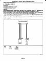
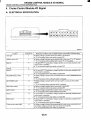
5. A/B Control Module I/O Signal
A: SCHEMATIC
<Ref. to WI-31, Airbag System.>
AB-20
91
AIRBAG CONNECTOR
AIRBAG SYSTEM (DIAGNOSTICS)
6. Airbag Connector
2. DRIVER'S AIRBAG, PASSENGER'S AIRBAG, AND SIDE AIRBAG
A: OPERATION
1. POWER SUPPLY
1) How to disconnect:
(1) Move the slide lock (A) in the direction of the
arrow.
(2) Pull the female connector in the direction of
the arrow with slide lock (A) moved.
*
1) How to disconnect:
(1) Push the lock arm (A).
(2) With lock arm (A) pushed in, move the slide
lock (B) in the direction of the arrow.
I
RE0012
CAUTION:
When pulling, be sure to hold onto the connector and not the wire.
2) How to connect:
Holding the connector (A), and push it in carefully
until a connecting sound is heard.
\ \
B5M1153AI
(3) With slide lock (B) pulled, remove the lock
arm (A) to its original position, and then pull in
the direction of the arrow and separate the connector.
CAUTION:
When pulling, be sure t o hold onto the connector and not the wire.
B5M1154
/
RE0015
CAUTION:
Be sure to insert the connector in until it locks.
Then pull on it gently t o make sure that it is
locked.
2) How to connect:
Holding the connector, and push it in carefully until
a connecting sound is heard.
CAUTION:
Be sure to insert the connector in until it locks.
Then pull on it gently to make sure that it is
locked.
AB-21
I
AIRBAG CONNECTOR
AIRBAG SYSTEM fDIAGNOSTICS)
3. FRONT SUB-SENSOR, SIDE AIRBAG
SENSOR
1) How to disconnect:
(1) Holding the outer part (A), pull it in the direction of the arrow.
CAUTION:
When pulling, be sure to hold onto the connector and not the wire.
(A)
2) How to connect:
Holding the connector, and push it in carefully until
a connecting sound is heard.
CAUTION:
Outer (A) moves back, and so do not put your
hand on the outer part.
Be sure to insert the connector in until it
locks. Then pull on it gently to make sure that it
is locked.
4. PRETENSIONER
1) How to disconnect:
(1) Move the slide lock (A) in the direction of the
arrow.
(2) Pull the connector (B) in the direction of the
arrow with slide lock (A) moved.
/
/
1
CAUTION:
When pulling, be sure to hold onto the connector and not the wire.
2) How to connect:
Holding the connector (A), and push it in carefully
until a connecting sound is heard.
CAUTION:
Be sure to insert the connector in until it locks.
Then pull on it gently to make sure that it is
locked.
AB-22
AIRBAG WARNING LIGHT ILLUMINATION PATTERN
AIRBAG SYSTEM (DIAGNOSTICS)
7. Airbag Warning Light Illumination Pattern
A: INSPECTION
Keep the ignition switch ON, and confirm that the
airbag warning light remains off approximately 6
seconds after being turned on.
Approx. 6 seconds
Airbag warning ON
light
OFF
A-1m
igniiion
switch ON
I
READ DIAGNOSTIC TROUBLE CODE
AIRBAG SYSTEM (DIAGNOSTICS)
8. Read Diagnostic Trouble
Code
3) Read trouble code by identifying the way the air
bag warning light flashes.
The airbag warning light flashes a code corresponding to the faulty parts.
The long segment (1.2 sec on) indicates a “ten”,
and the short segment (0.3 sec on) indicates a
“0ne”.
A: OPERATION
1) Turn the ignition switch ON.
2) Connect the diagnosis terminal (1) to the diagnosis connector (2) terminal No. 1 in the driver’s seat
lower cover area.
NOTE:
“List of Diagnostic Trouble Code” <Ref. to AB-32,
List of Diagnostic Trouble Code.>
“Airbag Warning Light Failure” <Ref. to AB-27,
Airbag Warning Light Failure.>
Example:
Flashing
code 12:
Flashing
code21:
OFF
-
10
1.2
-
10
,. 0.3 _.
1.2
r
1
.
0.3
1
.
1.2
0.3
1’
1
(Set)
Flashing
normal
code:
B5M0117A
4) Turn the ignition switch OFF, and disconnect the
diagnosis terminal from the diagnosis connector
terminal No 1.
5 ) Wind the tape around the diagnosis terminal and
return it to its original position.
AB-24
INSPECTION MODE
AIRBAG SYSTEM (DIAGNOSTICS)
9. Inspection Mode
A: OPERATION
According to the contents of check list, reproduce
the condition which problem has occurred as much
as possible.
AB-25
I
CLEAR MEMORY MODE
AIRBAG SYSTEM (DIAGNOSTICS)
1O.Clear Memory Mode
A: OPERATION
1) Turn the ignition switch ON.
2) Connect the diagnosis terminal (1) to the diagnosis connector (2) terminal No. 1 in the driver's seat
lower cover area.
3) While the warning light flashes, connect another
diagnosis terminal (3) to the diagnosis connector
Jerminal No.2.
4) Once the memory is erased, the warning light returns to the normal flash rate (0.6 sec on). The failure to recover the normal flash rate indicates that
trouble parts still remain. Having repaired such
parts, erase the memory again and confirm that the
normal flash rate has returned.
5) When the memory has been cleared, disconnect
the diagnosis terminal from the diagnosis connector.
6) Wind the tape around the diagnosis terminal and
return it to its original position.
AB-26
AIRBAG WARNING LIGHT FAILURE
AIRBAG SYSTEM (DIAGNOSTICS)
11.Airbag Warning Light Failure
A: AIRBAG WARNING LIGHT REMAINS ON.
DIAGNOSIS:
Airbag warning light unit is faulty.
Airbag control module to airbag warning light circuit is shorted or open.
Grounding circuit is faulty.
Airbag control module is faulty.
(AB1) and (831) are not connected properly.
(AB6) is not connected properly to airbag control module.
CAUTION:
Before diagnosing the airbag system, be sure to turn the ignition switch OFF, disconnect the
ground terminal from the battery, and wait more than 20 seconds before starting to work.
Before replacing the airbag module, seat belt pretensioner, roll connector, control module, and
sensor, reconnect each part and confirm that the warning light operates properly.
When inspecting the airbag main harness, disconnect the airbag module connector of the driver
and passenger seats for safety reasons.
AB-27
AIRBAG WARNING LIGHT FAILURE
AIRBAG SYSTEM (DIAGNOSTICS)
WIRING DIAGRAM:
N0.13
IG SW
I
T
J
"
=
=
=
=
INDICATOR
CIRCUIT
UI
r
m
k
I
@ AIRBAG CONTROL MODULE
RE0052
r
I
I
1
No
Check
Step
Go to step 2.
CHECK POOR CONTACT IN CONNECTORS I Is the Door contact in connecharness or replace
(ABl) AND (831).
tors (ABI) and (B31)?
the body harness
1)Turn the ignition switch OFF, disconnect the
with airbag main
battery ground terminal, and wait more than 20
harness.
seconds.
2)Remove the side sill cover. (Driver'sside)
3)Confirmthat firm contact is secured between
connectors (AB1 and (831).
AB-28
I
a
AIRBAG WARNING LIGHT FAILURE
AIRBAG SYSTEM (DIAGNOSTICS)
2
3
Yes
Check
Step
s the airbag warning light
Go to step 4.
CHECK AIRBAG WARNING LIGHT.
1)Turn the ignition switch OFF, disconnect the
battery ground terminal, and wait more than 20
seconds.
2)Connect the connector (11\11)in the test harness M to the body harness connector (831).
3)Connect the battery ground terminal and
turn the ignition switch ON.
4)Connect two connectors, (3M) and (4M) in
the test harness M.
s the anything unusual to body Repair the body
CHECK BODY HARNESS.
harness.
iarness?
Check the body harness.
NOTE:
After problem has been eliminated, disconnect
connectors (3M) and (4M).
No
;o to step 3.
3eplace combinaion meter printed
:ircuit. <Ref. to
DI-11, Combinaion Meter Assem,lY.>
So to step 5.
i
s the poor contact in connecCHECK POOR CONTACT.
or (AB6)?
Confirm that the firm contact is secured
between the airbag control module and the
connector (AB6). <Ref. to AB-15, Airbag Control Module.>
s the airbag warning light
CHECK AIRBAG MAIN HARNESS.
1)Turn the ignition switch OFF, disconnect the urned off?
battery ground terminal, and wait more than 20
seconds.
2)Connect the connector (ABI) to (831).
3)Disconnect the connectors (AB3) and (AB8).
4)Remove the glove box and disconnect the
connectors (AB10) and (AB9).
5)Disconnect the connector (AB6) from the airbag control module, and connect the connector
(1I) in the test harness I or 12. <Ref. to AB-15,
Airbag Control Module.>
6)Connect the battery ground terminal and
turn the ignition switch ON.
7)Connect the connectors (41) and (51) in the
test harness I or 12.
NOTE:
After problem has been eliminated, disconnecl
connectors (41) and (51).
CHECK GROUNDING CIRCUIT.
1)Turn the ignition switch OFF, disconnect the 2?
battery ground terminal, and wait more than 20
seconds.
2)Disconnect the connector (AB6) from the airbag control module.
3)Connect the connector (1I) in the test harness I or 12 to body harness connector (AB6).
4)Measure the resistance between connector
(21) in the test harness I or 12 and the chassis
ground.
Connector & terminal
(21) No. 9 - Chassis ground:
(211 No. 10 - Chassis wound:
AB-29
Replace the body
harness with airbag main harness
or replace the airbag control module. <Ref. to AB15, Airbag Control
Module.>
3eplace the body
Go to step 6.
iarness with air)ag main harness
control module.
<Ref. to AB-15,
Airbag Control
3epair bodyjrounding circuit.
I
AIRBAG WARNING LIGHT FAILURE
AIRBAG SYSTEM (DIAGNOSTICS)
B: AIRBAG WARNING LIGHT REMAINS OFF.
DIAGNOSIS:
Fuse No. 13 (in fuse box) is blown.
Body harness circuit is open.
Airbag warning light is faulty.
Airbag main harness is faulty.
Airbag control module is faulty.
CAUTION:
Before diagnosing the airbag system, be sure to turn the ignition switch OFF, disconnect the
ground terminal from the battery, and wait more than 20 seconds before starting to work.
Before replacing the airbag module, seat belt pretensioner, roll connector, control module, and
sensor, reconnect each part and confirm that the warning light operates properly.
When inspecting the airbag main harness, disconnect the airbag module connector of the driver
and passenger seats for safety reasons.
WIRING DIAGRAM:
1
F
I
@ AIRBAG CONTROL MODULE
RE0052
AB-30
AIRBAG WARNING LIGHT FAILURE
AIRBAG SYSTEM (DIAGNOSTICS)
Step
CHECK COMBINATION METER.
Turn the ignition switch ON, and confirm that
warning lights equipped in the combination
meter are turned on.
1
2
3
4
r-
-
Check
Do warning lights not for the
airbag turn on?
Yes
Go to step 2.
CHECK FUSE NO. 13 (IN MAIN FUSE BOX). Is the fuse No. 13 (in main fuse Replace the fuse
Remove the fuse No. 13 and perform visual
No. 13. If the fuse
box) blown?
inspection.
No. 13 blows
again, go to step
3.
CHECK AIRBAG WARNING LIGHT CIRCUIT Is the airbag warning light
Go to step 4.
(IN COMBINATION METER).
1)Turn the ignition switch OFF, disconnect the
battery ground terminal, and wait more than 20
seconds.
2)Disconnect the connector (ABI) from (831).
3)Connect the battery ground terminal and
turn the ignition switch ON.
CHECK AIRBAG MAIN HARNESS.
Is the airbag warning light
Replace the airbag
1)Turnthe ignition switch OFF, disconnect the turned on?
control module.
<Ref. to AB-15,
battery ground terminal, and wait more than 20
seconds.
Airbag Control
2)Connect the connector (ABI) to (831).
Module.>
3)Disconnect the connector (AB6) from the airbag control module. <Ref. to AB-15, Airbag
Control Module.>
4)Connect the battery ground terminal and
turn the ignition switch ON.
AB-31
No
Repair the combination meter
power supply.
<Ref. to 101-4,
Combination
Meter System.>
Go to step 3.
Replace the airbag
warning light bulb
or combination
meter printed circuit. <Ref. to IDI11, Combination
Meter Assembly.>
Replace the body
harness with airbag main harness.
I
LIST OF DIAGNOSTIC TROUBLE CODE
AIRBAG SYSTEM (DIAGNOSTICS)
12.List of Diagnostic Trouble Code
A: LIST
Memory
function
Contents of diagnosis
Index No.
Provided.
Airbag main harness circuit is open, shorted or
shorted to ground.
Airbag module harness (driver) circuit is open,
shorted or shorted to ground.
Roll connector circuit is open, shorted or shorted
to ground.
Airbag control module is faulty.
Driver's airbag module is faulty.
<Ref. to AB-36, TROUBLE CODE 11, Diagnostic Chart with
Trouble Code.>
Provided.
Airbag main harness circuit is open, shorted or
shorted to ground.
Airbag module harness (passenger) circuit is
open, shorted or shorted to ground.
Airbag control module is faulty.
Passenger's airbag module is faulty.
<Ref. to AB-38, TROUBLE CODE 12, Diagnostic Chart with
Trouble Code.>
Provided.
Airbag main harness circuit (driver) is shorted to
power supply.
Airbag module harness (driver) is shorted to power
supply.
Roll connector is shorted to power supply.
Airbag control module is faulty.
Driver's airbag module is faulty.
<Ref. to AB-40, TROUBLE CODE 15, Diagnostic Chart with
Trouble Code.>
Provided.
Airbag main harness circuit (passenger) is shorted
to power supply.
Airbag module harness (passenger) is shorted to
power supply.
Airbag control module is faulty.
Passenger's airbag module is faulty.
<Ref. to AB-42, TROUBLE CODE 16, Diagnostic Chart with
Trouble Code.>
Provided.
Airbag control module is faulty.
Provided.
Front airbag module and seat belt pretensioner (LH/
RH) are inflated.
Not provided.
(AB6), (AB17) and (AB18) are not connected properly to airbag control module.
Not provided.
Provided.
Provided.
Airbag control module is faulty.
Airbag main harness circuit is open.
Fuse No. 11 (in joint box) is blown.
Body harness circuit is open.
Airbag control module is faulty.
Airbag main harness circuit is open.
Fuse No. 6 (in joint box) is blown.
Body harness circuit is open.
Front sub-sensor harness (RH) circuit is shorted.
Front sub-sensor harness (RH) circuit is open.
Front sub-sensor (RH) is faulty.
Airbaq control module is faulty.
AB-32
<Ref. to AB-43, TROUBLE CODE 21, Diagnostic Chart with
Trouble Code.>
<Ref. to AB-44, TROUBLE CODE 22, Diagnostic Chart with
Trouble Code.>
<Ref. to AB-44, TROUBLE CODE 23, Diagnostic Chart with
Trouble Code.>
<Ref. to AB-46, TROUBLE CODE 24, Diagnostic Chart with
Trouble Code.>
<Ref. to AB-48, TROUBLE CODE 25, Diagnostic Chart with
Trouble Code.>
<Ref. to AB-50, TROUBLE CODE 31, Diagnostic Chart with
Trouble Code.>
LIST OF DIAGNOSTIC TROUBLE CODE
AIRBAG SYSTEM (DIAGNOSTICS)
Trouble code/
Contents of troubles
42
45
46
Memory
function
Provided.
Provided.
Provided.
Contents of diagnosis
Index No.
Front sub-sensor harness (LH) circuit is shorted.
Front sub-sensor harness (LH) circuit is open.
Front sub-sensor (LH) is faulty.
Airbag control module is faulty.
Side airbag harness (RH) is faulty.
Side airbag module (RH) is faulty.
Airbag control module is faulty.
<Ref. to AB-54, TROUBLE CODE 32, Diagnostic Chart with
Trouble Code.>
<Ref. to AB-58, TROUBLE CODE 41, Diagnostic Chart with
Trouble Code.>
_____
<Ref. to AB-60, TROUBLE CODE 42, Diagnostic Chart with
Trouble Code.>
<Ref. to AB-62, TROUBLE CODE 45, Diagnostic Chart with
Trouble Code.>
<Ref. to AB-64, TROUBLE CODE 46, Diagnostic Chart with
Trouble Code.>
<Ref. to AB-66, TROUBLE CODE 51, Diagnostic Chart with
Trouble Code.>
<Ref. to AB-68, TROUBLE CODE 52, Diagnostic Chart with
Trouble Code.>
<Ref. to AB-69, TROUBLE CODE 53, Diagnostic Chart with
Trouble Code.>
<Ref. to AB-69, TROUBLE CODE 54, Diagnostic Chart with
Trouble Code.>
<Ref. to AB-70, TROUBLE CODE 55, Diagnostic Chart with
Trouble Code.>
Side airbag harness (LH) is faulty.
Side airbag module (LH) is faulty.
Airbag control module is faulty.
Side airbag harness (RH) is shorted to power supPly.
Airbag control module is faulty.
Side airbag harness (LH) is shorted to power supPly.
Airbag control module is faulty.
-..
51
Provided.
Side airbag sensor (RH) is faulty.
Side airbag harness (RH) is faulty.
Airbag control module is faulty.
Side airbag sensor (LH) is faulty.
Side airbag harness (LH) is faulty.
Airbag control module is faulty.
52
Provided.
53
Provided.
Side airbag sensor (RH) is faulty.
54
Provided.
Side airbag sensor (LH) is faulty.
55
Provided.
Side airbag module is inflated.
61
Provided.
Seat belt pretensioner (RH) circuit is open, shorted
or shorted to ground.
Airbag control module is faulty.
Pretensioner is faulty.
Pretensioner harness is faulty.
Seat belt pretensioner (LH) circuit is open, shorted
or shorted to ground.
Airbag control module is faulty.
Pretensioner is faulty.
Pretensioner harness is faulty.
Seat belt pretensioner (RH) circuit is shorted to
power supply.
Pretensioner is faulty.
Pretensioner harness is faulty.
Airbag control module is faulty.
AB-33
<Ref. to AB-72, TROUBLE CODE 61, Diagnostic Chart with
Trouble Code.>
<Ref. to AB-74, Trouble
Code 62, Diagnostic
Chart with Trouble
Code.>
<Ref. to AB-76, TROUBLE CODE 65, Diagnostic Chart with
Trouble Code.>
Trouble codel
Contents of troubles
66
Memory
function
Provided.
Contents of diagnosis
Seat belt pretensioner (LH) circuit is shorted to
power supply.
Pretensioner is faulty.
Pretensioner harness is faulty.
Airbag control module is faulty.
AB-34
Index No.
<Ref. to AB-78, TROUBLE CODE 66, Diagnostic Chart with
Trouble Code.>
LIST OF DIAGNOSTIC TROUBLE CODE
AIRBAG SYSTEM (DIAGNOSTICS)
AB-35
DIAGNOSTIC CHART WITH TROUBLE CODE
AI RBAG SYSTEM (DIAGNOSTICS)
13.Diagnostic Chart with Trouble Code
A: TROUBLE CODE 11
DIAGNOSIS:
Airbag main harness circuit is open, shorted or shorted to ground.
Airbag module harness (Driver) circuit is open, shorted or shorted to ground.
Roll connector circuit is open, shorted or shorted to ground.
Driver's airbag module is faulty.
Airbag control module is faulty.
CAUTION:
Before diagnosing the airbag system, be sure to turn the ignition switch OFF, disconnect the
ground terminal from the battery, and wait more than 20 seconds before starting to work.
Before replacing the airbag module, seat belt pretensioner, roll connector, control module, and
sensor, reconnect each part and confirm that the warning light operates properly.
When inspecting the airbag main harness, disconnect the driver's airbag module and passenger's
airbag module connectors for safety reasons.
WIRING DIAGRAM:
@(YELLOW)
@(YELLOW)
B5M109f
AB-36
I
DIAGNOSTIC CHART WITH TROUBLE CODE
AIRBAG SYSTEM (DIAGNOSTICS)
Step
CHECK DRIVER'S AIRBAG MODULE.
1)Turn the ignition switch OFF, disconnect the
battery ground terminal, and wait more than 20
seconds.
2)Remove the driver's airbag module. <Ref. to
AB-12, Driver'sAirbag Module.>
3)Connect the connector (1F) in the test harness F to connector (AB7).
4)Connect the airbag resistor to connector (3F)
in the test harness F.
5)Connect the battery ground terminal and
turn the ignition switch ON.
CHECK ROLL CONNECTOR.
1)Turn the ignition switch OFF, disconnect the
battery ground terminal, and wait more than 20
seconds.
2)Disconnect the test harness F from the connector (AB7).
3)Remove the lower cover panel, disconnect
the connector (AB3) from (AB8) and connect
the connector (1F) in the test harness F to con.
nector (AB8).
4)Connect the airbag resistor to connector (3F)
in the test harness F.
5)Connect the battery ground terminal and
turn the ignition switch ON.
CHECK AIRBAG MAIN HARNESS.
1)Turn the ignition switch OFF, disconnect the
battery ground terminal, and wait more than 20
seconds.
2)Disconnect the airbag resistor from the connector (3F) in the test harness F.
3)Remove the glove box, <Ref. to AB-13, Passenger's Airbag Module.> and disconnect the
connectors (ABIO) and (AB9).
4)Disconnect the connector (AB6) from the airbag control module, and connect the connector
(1I) in the test harness I or 12. <Ref. to AB-15,
Airbag Control Module.>
5)Measure the resistance between connector
(21) in the test harness I or 12 and the connector (3F) in the test harness F.
Connector & terminal
(2l) NO. 1 - (3F) NO. 4:
(21) NO. 4 - (3F) NO. 3:
CHECK AIRBAG MAIN HARNESS.
Measure the resistance of the connector (21) in
the test harness I or 12.
Connector & terminal
(21) NO. 1 -NO. 4:
(21) No. 4 - Chassis ground:
(21) No. 1 - Chassis ground:
Check
)oes the airbag warning light
iperate properly?
Yes
3eplace the
iriver's airbag
nodule. <Ref. to
4B-12, Driver's
4irbag Module.>
)oes the airbag warning light
iperate properly?
3eplace the roll
:onnector. <Ref.
o AB-17, Roll
:onnector.>
30 to step 3.
;the resistance less than 10
;o to step 4.
3eplace the body
iarness with airlag main harness
1?
;the resistance more than 1
1R?
AB-37
No
30 to step 2.
3eplace the airbag 3eplace the body
iarness with air:ontrol module.
:Ref. to AB-15,
)ag main harness
\irbag Control
Aodule.>
DIAGNOSTIC CHART WITH TROUBLE CODE
AIRBAG SYSTEM (DIAGNOSTICS)
~
B: TROUBLE CODE 12
DIAGNOSIS:
Airbag main harness circuit is open, shorted or shorted to ground.
Airbag module harness (Passenger) circuit is open, shorted or shorted to ground.
Passenger's airbag module is faulty.
Airbag control module is faulty.
CAUTION:
Before diagnosing the airbag system, be sure to turn the ignition switch OFF, disconnect the
ground terminal from the battery, and wait more than 20 seconds before starting to work.
Before replacing the airbag module, seat belt pretensioner, roll connector, control module, and
sensor, reconnect each part and confirm that the warning light operates properly.
When inspecting the airbag main harness, disconnect the airbag module connector of the driver
and passenger seats for safety reasons.
WIRING DIAGRAM:
@ AIRBAG CONTROL MODULE
INFLATOR
(PASSENGER SIDE)
AB-38
DIAGNOSTIC CHART WITH TROUBLE CODE
AIRBAG SYSTEM (DIAGNOSTICS)
~
I
!
r-
I
Step
CHECK PASSENGER'SAIRBAG MODULE.
1)Turn the ignition switch OFF, disconnect the
battery ground terminal, and wait more than 20
seconds.
2)Remove the glove box.
3)Disconnect the connector (AB10) from
(AB9).
4)Connect the connector (1F) in the test harness F to connector (AB9).
5)Connect the airbag resistor to connector (3F)
in the test harness F.
6)Connect the battery ground terminal and
turn the ignition switch ON.
CHECK AIRBAG MAIN HARNESS.
s the resistance less than 10
1)Turn the ignition switch OFF, disconnect the Z?
battery ground terminal, and wait more than 20
seconds.
2)Disconnect the airbag resistor from the connector (3F) in test harness F.
3)Remove lower cover and disconnect the connector (AB3) from (AB8).
4)Disconnect the connector (AB6) from the airbag control module, and connect the connector
(1I) in the test harness I or 12. <Ref. to AB-15,
Airbag Control Module.>
5)Measure the resistance between connector
(21) in the test harness I or 12 and the connector (3F) in the test harness F.
Connector & terminal
(21) NO. 2 - (3F) NO. 3:
(21) NO. 5 - (3F) NO. 4:
CHECK AIRBAG MAIN HARNESS.
s the resistance more than 1
Measure the resistance of the connector (21) in An?
the test harness I or 12.
Connector 81terminal
(21)NO. 2 NO. 5:
(21)No. 2 Chassis ground:
(21) No. 5 Chassis ground:
-
AB-39
No
;o to step 2.
I
Go to step 3.
leplace the body
iarness with airlag main harness.
eeplace airbag
control module.
<Ref. to AB-15,
Airbag Control
Module.>
leplace the body
larness with airlag main harness.
I
DIAGNOSTIC CHART WITH TROUBLE CODE
AIRBAG SYSTEM (DIAGNOSTICS)
C: TROUBLE CODE 15
DIAGNOSIS:
Airbag main harness circuit (Driver) is shorted to the power supply.
Airbag module harness (Driver) is shorted to the power supply.
Roll connector is shorted to the power supply.
Driver's airbag module is faulty.
Airbag control module is faulty.
CAUTION:
Before diagnosing the airbag system, be sure to turn the ignition switch OFF, disconnect the
ground terminal from the battery, and wait more than 20 seconds before starting to work.
Before replacing the airbag module, seat belt pretensioner, roll connector, control module, and
sensor, reconnect each part and confirm that the warning light operates properly.
When inspecting the airbag main harness, disconnect the driver's airbag module and passenger's
airbag module connectors for safety reasons.
WIRING DIAGRAM:
AB6
AIRBAG CONTROL MODULE
IO
r
I
STEERING
ROLL CONNECTOR
U
INFLATOR
@(YELLOW)
@(YELLOW)
@(YELLOW)
m
B5M109t
AB-40
DIAGNOSTIC CHART WITH TROUBLE CODE
AIRBAG SYSTEM (DIAGNOSTICS)
I
?
r-
i
Step
CHECK DRIVER'SAIRBAG MODULE.
1)Turn the ignition switch OFF, disconnect the
battery ground terminal, and wait more than 20
seconds.
2)Remove the driver's airbag module. <Ref. to
AB-12, Driver's Airbag Module.>
3)Connect the connector (AB7) to connector
(1F) in the test harness F.
4)Connect the airbag resistor to connector (3F)
in the test harness F.
5)Connect the battery ground terminal and
turn the ignition switch ON.
CHECK ROLL CONNECTOR.
1)Turn the ignition switch OFF, disconnect the
battery ground terminal, and wait more than 20
seconds.
2)Disconnect the test harness F from the connector (AB7).
3)Remove the lower cover panel and disconnect the connector (AB3) from (AB8).
4)Connect the connector (1F) in the test harness F to the connector (AB8).
5)Connect the airbag resistor to connector (3F)
in the test harness F.
6)Connect the battery ground terminal and
turn the ignition switch ON.
CHECK AIRBAG MAIN HARNESS.
1)Turnthe ignition switch OFF, disconnect the
battery ground terminal, and wait more than 20
seconds.
2)Disconnect the airbag resistor from the connector (3F) in test harness F.
3)Remove the glove box, and disconnect the
connectors (AB10) and (AB9).
4)Disconnect the connector (AB6) from the airbag control module, and connect the connector
(1I) in the test harness I or 12. <Ref. to AB-1 5,
Airbag Control Module.>
5)Connect the battery ground terminal and
turn the ignition switch ON. (Engine OFF)
6)Measure the voltage between connector (21)
in the test harness I or 12 and the chassis
ground.
Connector & terminal
(21) No. 4 (+) - Chassis groundI)-(
(21) No. 1 (+) - Chassis ground (-):
Check
Ioes the airbag warning light
)perate properly?
Yes
Replace the
driver's airbag
module. <Ref. to
AB-12, Driver's
Airbag Module.>
Ioes the airbag warning light
)perate properly?
Replace the roll
connector. <Ref.
to AB-17 , Roll
Connector.>
No
20 to step 2.
20 to step 3.
I
control module.
<Ref. to AB-15,
Airbag Control
Module.>
AB-41
3eplace the body
iarness with air)ag main harness.
I
DIAGNOSTIC CHART WITH TROUBLE CODE
AIRBAG SYSTEM (DIAGNOSTICS)
D: TROUBLE CODE 16
DIAGNOSIS:
Airbag main harness circuit (Passenger) is shorted to the power supply.
Airbag module harness (Passenger) is shorted to the power supply.
Passenger's airbag module is faulty.
Airbag control module is faulty.
CAUTION:
Before diagnosing the airbag system, be sure to turn the ignition switch OFF, disconnect the
ground terminal from the battery, and wait more than 20 seconds before starting to work.
Before replacing the airbag module, seat belt pretensioner, roll connector, control module, and
sensor, reconnect each part and confirm that the warning light operates properly.
When inspecting the airbag main harness, disconnect the airbag module connector of the driver
and passenger seats for safety reasons.
WIRING DIAGRAM:
r
INFLATOR
(PASSENGER SIDE)
1
RE0053
AB-42
DIAGNOSTIC CHART WITH TROUBLE CODE
AIRBAG SYSTEM (DIAGNOSTICS)
!
r-
Step
CHECK PASSENGER'S AIRBAG MODULE.
1)Turn the ignition switch OFF, disconnect the
battery ground terminal, and wait more than 20
seconds.
2)Remve the glove box.
3)Disconnect the connector (AB10) from (AB9
4)Connect the connector (1F) in the test harness F to the connector (AB9).
5)Connect the airbag resistor to connector (3F)
in the test harness F.
6)Connect the battery ground terminal and
turn the ignition switch ON.
CHECK AIRBAG MAIN HARNESS.
1)Turn the ignition switch OFF, disconnect the
battery ground terminal, and wait more than 20
seconds.
2)Disconnect the airbag resistor from the connector (3F) in the test harness F.
3)Remove the lower cover and disconnect the
connector (AB3) from (AB8).
4)Disconnect the connector (AB6) from the air
bag control module, and connect the connector
(1I) in the test harness I or 12. <Ref. to AB-15,
Airbag Control Module.>
5)Measure the voltage between connector (21)
in the test harness I or 12 and the chassis
ground.
Connector & terminal
(21) No. 2 - Chassis ground:
(21) No. 5 - Chassis ground:
Check
)es the airbag warning light
'erate properly?
;enger airbag
nodule. <Ref. to
4B-I 3, Passenjerk Airbag Mod-
the voltage less than 1 V?
4irbag Control
vlodu1e.r
E: TROUBLE CODE 21
DIAGNOSIS:
Airbag control module is faulty.
CAUTION:
Before diagnosing the airbag system, be sure to turn the ignition switch OFF, disconnect the
ground terminal from the battery, and wait more than 20 seconds before starting to work.
Before replacing the airbag module, seat belt pretensioner, roll connector, control module, and
sensor, reconnect each part and confirm that the warning light operates properly.
1
Check
Step
CHECK IF TROUBLE CODE 21 IS INDICAT- Is the airbag warning light trouble code 21 indicated?
ED.
Read Diagnostic Trouble Code. <Ref. to AB24, Read Diagnostic Trouble Code.>
AB-43
Yes
Replacethe airbag
control module.
<Ref. to AB-15,
Airbag Control
Module.>
No
Perform clear
memory. <Ref. to
AB-26, Clear
Memory Mode.>
I
DIAGNOSTIC CHART WITH TROUBLE CODE
AIRBAG SYSTEM (DIAGNOSTICS)
F: TROUBLE CODE 22
This code is indicated when the front airbag and the
pretensioner are in operation.
Once this code is indicated, memory is not erasable; therefore replace the following parts.
Airbag control module. <Ref. to AB-15 , Airbag Control Module.>
Driver's airbag module. <Ref. to AB-12, Driver's Airbag Module.>
Passenger's airbag module. <Ref. to AB-13, Passenger's Airbag Module.>
Front sub-sensor of both sides. <Ref. to AB-18, Front Sub Sensor.>
Front seat belt outer with pretensioner of both sides. <Ref. to SB-8, Front Seat Belt.>
G: TROUBLE CODE 23
DIAGNOSIS:
(AB6), (AB17) and (AB18) are not connected properly to airbag control module.
CAUTION:
Before diagnosing the airbag system, be sure to turn the ignition switch OFF, disconnect the ground
terminal from the battery, and wait more than 20 seconds before starting to work.
1
..
2
Step
CHECK POOR CONTACT IN CONECTORS
(Ass), (AB17) and (AB18).
1)Turn the ignition switch OFF, disconnect the
battery ground terminal, and wait more than 20
seconds.
2)Disconnect the connectors (AB6), (AB17)
and (AB18) from the airbag control module.
<Ref. to AB-15, Airbag Control Module.>
Check
Check if the rust or damage
appear on the harness connector and the control module
connector.
CHECKPOORCONTACTINCONECTORS
operate properly?
(Ass), (AB17) and (AB18).
1)Ensure that the connectors are firmly reconnected.
2)Connect the battery ground terminal and
turn the ignition switch ON.
AB-44
Yes
No
Replace the airbag Go to step 2.
control module.
<Ref. to AB-15,
Airbag Control
Module.> Replace
the body harness
with airbag main
harness.
Replace the body
harness with side
airbag harness.
I
Finish the diagno- I Replace the airbag
control module.
sis.
<Ref. to AB-15,
Airbag Control
Module.>
I
DIAGNOSTIC CHART WITH TROUBLE CODE
AIRBAG SYSTEM (DIAGNOSTICS)
AB-45
DIAGNOSTIC CHART WITH TROUBLE CODE
AIRBAG SYSTEM (DIAGNOSTICS)
H: TROUBLE CODE 24
DIAGNOSIS:
Airbag control module is faulty.
Airbag main harness circuit is open.
Fuse No, 11 (in joint box) is blown.
Body harness circuit is open.
CAUTION:
Before diagnosing the airbag system, be sure to turn the ignition switch OFF, disconnect the
ground terminal from the battery, and wait more than 20 seconds before starting to work.
Before replacing the airbag module, seat belt pretensioner, roll connector, control module, and
sensor, reconnect each part and confirm that the warning light operates properly.
When inspecting the airbag main harness, disconnect the driver's airbag module and passenger's
airbag module connectors for safety reasons.
WIRING DIAGRAM:
IG SW
N0.11
1
I
I
I
W
AIRBAG CONTROL MODULE
I
RE0054
AB-46
m
DIAGNOSTIC CHART WITH TROUBLE CODE
At RBAG SYSTEM (DIAGNOSTICS)
Yes
Check
3 the voltage more than 10 V? 3eplace the airbag
CHECK AIRBAG CONTROL MODULE.
:ontrol module.
1)Turn the ignition switch OFF, disconnect the
:Ref. to AB-15,
battery ground terminal, and wait more than 20
4irbag Control
seconds.
vlodule.>
2)Disconnect the connector (AB6) from the airbag control module. <Ref. to AB-15, Airbag
Control Module.>
3)Connect the connector (1I) in the test harness I or 12 to connector (AB6).
4)Connect the battery ground terminal and
turn the ignition switch ON.
5)Measure the voltage between connector (21)
in the test harness I or 12 and chassis ground.
Connector & terminal
(21) No. 3 (+) - Chassis ground (-):
s the resistance less than 10 30 to step 3.
CHECK AIRBAG MAIN HARNESS.
1)While checking control module, turn the igni- 2?
tion switch OFF and disconnect the battery
ground terminal. Wait more than 20 seconds
before operation.
2)Disconnect the airbag connector (AB1) from
the body harness (B31).
3)Connect the connector (2M) in the test harness M to connector (AB1).
4)Measure the resistance between connector
(5M) in the test harness M and the connector
(21) in the test harness I or 12.
Connector & terminal
(5M) NO. 2 - (21) NO. 3:
s the resistance more than 1 30 to step 4.
CHECK AIRBAG MAIN HARNESS.
dfi?
Measure the following resistance with the
above-mentioned condition maintained.
Connector & terminal
(5M) No. 2 - Chassis ground:
(21) No. 3 - Chassis ground:
3eplace fuse No.
s fuse No. 11 blown?
CHECK FUSE No. 11 (IN JOINT BOX).
11. Iffuse No. 11
1)Confirmthat the ignition switch is turned
lows again, repair
OFF.
:he body harness.
2)Remove the fuse No. 11 (in joint box) and
perform visual inspection.
Step
AB-47
No
) to step 2.
?placethe body
.messwith air.g main harness.
?placethe body
irness with airig main harness
?pairthe body
irness.
I
DIAGNOSTIC CHART WITH TROUBLE CODE
AIRBAG SYSTEM (DIAGNOSTICS)
I: TROUBLE CODE 25
DIAGNOSIS:
Airbag control module is faulty.
Airbag main harness circuit is open.
Fuse No. 6 (in joint box) is blown.
Body harness circuit is open.
CAUTION:
Before diagnosing the airbag system, be sure to turn the ignition switch OFF, disconnect the
ground terminal from the battery, and wait more than 20 seconds before starting to work.
Before replacing the airbag module, seat belt pretensioner, roll connector, control module, and
sensor, reconnect each part and confirm that the warning light operates properly.
When inspecting the airbag main harness, disconnect the driver's airbag module and passenger's
airbag module connectors for safety reasons.
WIRING DIAGRAM:
r Y
AB6
AIRBAG CONTROL MODULE
RE0055
AB-48
m
DIAGNOSTIC CHART WITH TROUBLE CODE
AIRBAG SYSTEM (DIAGNOSTICS)
~~
!
-. .
1
I
~~
~
Step
CHECK AIRBAG CONTROL MODULE.
1)Turn the ignition switch OFF, disconnect the
battery ground terminal, and wait more than 20
seconds.
2)Disconnect the connector (AB6) from airbag
control module. <Ref. to AB-15, Airbag Control
Module.>
3)Connect the connector (1 I ) in the test harness I or 12 to the connector (AB6).
4)Connect the battery ground cable, and turn
the ignition switch ON.
5)Measure the voltage between the connector
(21) in the test harness I or 12 and the chassis
ground.
Connector & terminal
(21) No. 6 (+) - Chassis ground (-):
CHECK AIRBAG MAIN HARNESS.
1) While checking control module, turn the igni
tion switch OFF and disconnect the battery
ground terminal. Wait more than 20 seconds
before operation.
2)Disconnect the airbag connector (ABI) from
the body harness (B31).
3)Connect the connector (2M) in the test harness M to the airbag connector (AB1).
4)Measure the resistance between the connector (5M) in the test harness M and the connector (21) in the test harness I or 12.
Connector & terminal
(5M) NO. 2 - (20 NO. 6:
CHECK AIRBAG MAIN HARNESS.
Measure the following resistance with the
above-mentionedcondition maintained.
Connector & terminal
(5M) No. 2 - Chassis ground:
(21) No. 6 - Chassis ground:
CHECK FUSE NO. 6 (IN JOINT BOX).
1)Confirm that the ignition switch is turned
OFF.
2)Remove the fuse No. 6 (in joint box) and per
form visual inspection.
No
Check
Yes
the voltage more than 10 V? Replace the airbag i o to step 2.
control module.
<Ref. to AB-15,
Airbag Control
Module.>
the resistance less than 10
I Go to step 3.
3eplace the body
iarness with air)ag main harness
0
1
the resistance more than 1
Go to step 4.
No. 6. If the fuse
No. 6 is blown
again, repair the
bodv harness.
AB-49
3eplace the body
iarness with airlag main harness
3epair the body
iarness.
I
DIAGNOSTIC CHART WITH TROUBLE CODE
AIRBAG SYSTEM (DIAGNOSTICS)
J: TROUBLE CODE 31
DIAGNOSIS:
Front sub-sensor harness (RH) circuit is shorted.
Front sub-sensor harness (RH) circuit is open.
Front sub-sensor (RH) is faulty.
Airbag control module is faulty.
CAUTION:
Before diagnosing the airbag system, be sure to turn the ignition switch OFF, disconnect the
ground terminal from the battery, and wait more than 20 seconds before starting to work.
Before replacing the airbag module, seat belt pretensioner, roll connector, control module, and
sensor, reconnect each part and confirm that the warning light operates properly.
When inspecting the airbag main harness, disconnect the driver's airbag module and passenger's
airbag module connectors for safety reasons.
WIRING DIAGRAM:
7
E
AB6
AIRBAG CONTROL MODULE
m
FRONT SUB SENSOR RH
RE0029
AB-50
iim
DIAGNOSTIC CHART WITH TROUBLE CODE
AI RBAG SYSTEM (DIAG NOSTICS1
Step
CHECK FRONT SUB-SENSOR (RH) AND
FRONT SUB-SENSOR HARNESS (RH).
Connector & terminal
(31) NO.2 - NO. 4:
CHECK FRONT SUB-SENSOR (RH) AND
FRONT SUB-SENSOR HARNESS (RH).
Measure the resistance between connector
(31) in the test harness I or 12 and the chassis
ground.
Connector & terminal
Chassis ground:
(31) No. 2
(31) No. 4 - Chassis ground:
CHECK AIRBAG MAIN HARNESS AND
FRONT SUB-SENSOR HARNESS (RH).
1)Disconnectthe connector (AB16) from the
front sub-sensor. <Ref. to AB-18, Front Sub
Sensor.>
2)Connect the connector (IH) in test harness H
to the connector (AB16).
3)Measure the resistance between connector
(31) in test harness I or 12 and connector (3H)
in the test harness H.
Connector & terminal
(31) NO. 2 - (3H) NO. 5:
(31) NO. 4 - (3H) NO. 6:
CHECK AIRBAG MAIN HARNESS AND
FRONT SUB-SENSOR HARNESS (RH).
Measure the resistance between connector
(31) in the test harness I or 12 and the chassis
ground.
Connector & terminal
(3l) No. 2 Chassis ground:
Chassis ground:
(31) No. 4
CHECK AIRBAG MAIN HARNESS
1)Disconnect the connector (AB15) from
(AB14), and connect the connector (1F) in test
harness F to the connector (AB14).
2)Measure the resistance between connector
(31) in the test harness I or 12 and connector
(3F) in the test harness F.
Connector & terminal
(31) NO. 2 - (3F) NO. 4:
(31) NO. 4 -(3F) NO. 3:
CHECK AIRBAG MAIN HARNESS
Measure the resistance between connector
(31) in the test harness I or 12 and the chassis
ground.
Connector & terminal
(31) No. 2 - Chassis ground:
(31) No. 4 - Chassis ground:
Check
Is the resistance between
7500 and 1 KQ?
Yes
30 to step 2.
No
I Go to step 3.
Is the resistance more than 1
MQ?
3eplace the airbag Go to step 3.
:ontrol module.
:Ref. to AB-15,
4irbag Control
vlodule.>
Is the resistance less than
1on?
20 to step 4.
Go to step 5.
Is the resistance more than 1
20 to step 10.
Go to step 5.
Is the resistance less than 10
R?
20 to step 6.
Replace the body
harness with airbag main harness
Is the resistance more than 1
MR?
20 to step 7.
Replace the body
harness with airbag main harness
-
MQ?
-
AB-51
I
DIAGNOSTIC CHART WITH TROUBLE CODE
AIRBAG SYSTEM (DIAGNOSTICS)
I
I
0
1
Step
CHECK FRONT SUB-SENSOR HARNESS
(RH).
1)Connect the connector (2F) in the test harness F to the connector (AB1 5).
2)Measure the resistance between connector
(3H) in the test harness H and connector (3F)
in the test harness F.
Connector & terminal
(3F) NO.5 - (3H) NO. 5:
(3F) NO. 6 - (3H) NO. 6:
CHECK FRONT SUB-SENSOR HARNESS
(RH).
Measure the resistance between connector
(3H) in the test harness H and connector (3F)
in the test harness F.
Connector & terminal
(3F) NO. 6 - (3H) NO. 6:
(3F) NO. 5 - (3H) NO. 5:
CHECK FRONT SUB-SENSOR HARNESS
(RH).
Measure the resistance between connector
(3F) in the test harness F and the chassis
ground.
Connector & terminal
(3F) No. 5 - Chassis ground:
(3F) No. 6 - Chassis ground:
CHECK FRONT SUB-SENSOR (RH).
1)Connect the connector (2H) in test harness
H to the front sub-sensor (RH).
2)Measure the resistance of the connector
(3H) in the test harness H.
Connector & terminal
(3H) NO. 3 - NO. 4:
CHECK FRONT SUB-SENSOR (RH).
Measure the resistance between connector
(3H) in the test harness H and the chassis
ground.
Connector & terminal
(3H) No. 3 - Chassis ground:
(3H) No. 4 - Chassis ground:
Check
Is the resistance less than 10
Yes
30 to step 8.
R?
Is the resistance more than 1M 20 to step 9.
R?
No
Replace the body
harness with front
sub-sensor harness (RH).
Replace the body
harness with front
sub-sensor harness.
Is the resistance more than 1
MR?
20 to step 10.
Replace the body
harness with front
sub-sensor harness (RH).
Is the resistance between
i o to step 11.
Replace the front
sub-sensor (RH).
<Ref. to AB-1 8,
Front Sub Sensor.>
750R and 1 KR?
Is the resistance more than 1
MR?
AB-52
'inish the diagno- Replace the front
;is.
sub-sensor (RH).
<Ref. to AB-1 8,
Front Sub Senso r.>
I
DIAGNOSTIC CHART WITH TROUBLE CODE
AIRBAG SYSTEM (DIAGNOSTICS)
AB-53
I
DIAGNOSTIC CHART WITH TROUBLE CODE
AIRBAG SYSTEM (DIAGNOSTICS)
K: TROUBLE CODE 32
DIAGNOSIS:
Front sub-sensor harness (LH) circuit is shorted.
Front sub-sensor harness (LH) circuit is open.
Front sub-sensor (LH) is faulty.
Airbag control module is faulty.
CAUTION:
Before diagnosing the airbag system, be sure to turn the ignition switch OFF, disconnect the
ground terminal from the battery, and wait more than 20 seconds before starting to work.
Before replacing the airbag module, seat belt pretensioner, roll connector, control module, and
sensor, reconnect each part and confirm that the warning light operates properly.
When inspecting the airbag main harness, disconnect the driver's airbag module and passenger's
airbag module connectors for safety reasons.
WIRING DIAGRAM:
r
AB6
t
AIRBAG CONTROL MODULE
rA
I
I
FRONT SUB SENSOR LH
RE0056
AB-54
a
DIAGNOSTIC CHART WITH TROUBLE CODE
AIRBAG SYSTEM (DIAGNOSTICS)
1
2
-3
4
5
6
Step
CHECK FRONT SUB-SENSOR (LH) AND
FRONT SUB-SENSOR HARNESS (RH).
1)Turn the ignition switch OFF, disconnect the
battery ground terminal, and wait more than 20
seconds.
2)Disconnect the connector (AB6) from the airbag control module, and connect connector
(1I) in the test harness I or 12 to the connector
(AB6). <Ref. to AB-1 5, Airbag Control Module.>
3)Measure the resistance of the connector (31)
in the test harness I or 12.
Connector & terminal
(31) NO. 1 -NO. 3:
CHECK FRONT SUB-SENSOR (LH) AND
FRONT SUB-SENSOR HARNESS (RH).
Measure the resistance between connector
(31) in the test harness I or 12 and the chassis
ground.
Connector & terminal
(34 No. 1 - Chassis ground:
(31) No. 3 - Chassis ground:
CHECK AIRBAG MAIN HARNESS AND
FRONT SUB-SENSOR HARNESS (LH).
1)Disconnectthe connector (AB13) from the
front sub-sensor. <Ref. to AB-18, Front Sub
Sensor.>
2)Connect the connector (1H) in the test harness H to the connector (AB13).
3)Measure the resistance between connector
(31) in the test harness I or 12 and connector
(3H)in the test harness H.
Connector & terminal
(31) NO. 3 - (3H) NO. 6:
(31) NO. 1 -(3H) NO. 5:
CHECK AIRBAG MAIN HARNESS AND
FRONT SUB-SENSOR HARNESS (LH).
Measure the resistance between connector
(31) in the test harness I or 12 and the chassis
ground.
Connector & terminal
(31) No. 3 - Chassis ground:
(31) No. 1 - Chassis ground:
CHECK AIRBAG MAIN HARNESS.
1)Disconnect the connector (AB11) from
(AB12), and connect the connector (IF) in the
test harness F to (AB11).
2)Measure the resistance between connector
(31) in the test harness I or 12 and connector
(3F) in the test harness F.
Connector & terminal
(31) NO. 3 -(3F) NO. 3:
(31) NO. 1 - (3F) NO. 4:
CHECK AIRBAG MAIN HARNESS.
Measure the resistance between connector
(31) in the test harness I or 12 and the chassis
ground.
Connector & terminal
(31) No. 3 - Chassis ground:
(31) No. 1 - Chassis ground:
No
Go to step 3.
Check
5 the resistance between
‘50Q and 1 KR?
Yes
30 to step 2.
s the resistance more than 1
AQ?
3eplace the airbag Go to step 3.
:ontrol module.
:Ref. to AB-15,
4irbag Control
vlodu1e.i
s the resistance less than 10
30 to step 4.
I Go to step 5.
2?
3
s the resistance more than 1
AR?
30 to step 10.
s the resistance less than 10
2?
30 to step 6.
s the resistance more than 1
AR?
Go to step 5.
r
Replace the body
harness with airbag main harness
harness with airbag main harness
I
DIAGNOSTIC CHART WITH TROUBLE CODE
AIRBAG SYSTEM (DIAGNOSTICS)
,
1
1
0
1
Step
CHECK FRONT SUB-SENSOR HARNESS
(LH).
1)Connect the connector (2F) in the test harness F to the connector (AB12).
2)Measure the resistance between connector
(3H) in the test harness H and connector (3F)
in the test harness F.
Connector & terminal
(3F) NO. 5 - (3H) NO. 5:
(3F) NO. 6 - (3H) NO. 6:
CHECK FRONT SUB-SENSOR HARNESS
W).
Measure the resistance between connector
(3H) in the test harness H and connector (3F)
in the test harness F.
Connector & terminal
(3F) NO. 6 - (3H) NO. 6:
(3F) NO. 5 - (3H) NO. 5:
CHECK FRONT SUB-SENSOR HARNESS
(LW
Measure the resistance between connector
(3F) in the test harness F and the chassis
ground.
Connector & terminal
(3F) No. 5 - Chassis ground:
(3F) No. 6 - Chassis ground:
CHECK FRONT SUB-SENSOR (LH).
1)Coonect connector (2H) in the test harness
H to the front sub-sensor (LH).
2)Measure the resistance of the connector
(3H) in the test harness H.
Connector & terminal
(3H) NO. 3 -NO. 4:
CHECK FRONT SUB-SENSOR (LH).
Measure the resistance between connector
(3H) in the test harness H and the chassis
ground.
Connector & terminal
(3H) No. 3 - Chassis ground:
(3H) No. 4 - Chassis ground:
Check
the resistance less than 10
?
Yes
30 to step 8.
the resistance more than 1M 30 to step 9.
?
No
Replace the body
harness with front
sub-sensor harness (LH).
Replace the body
harness with front
sub-sensor harness (LH).
the resistance more than 1
30 to step 10.
Replace the body
harness with front
sub-sensor harness (LH).
the resistance between
OR and 1 KR?
30 to step 11.
Replace the front
sub-sensor (LH).
<Ref. to AB-18,
Front Sub Sensor.>
the resistance more than 1
-inish the diagno- Replace the front
;is.
sub-sensor (LH).
<Ref. to AB-18,
Front Sub Sensor.>
n?
n?
AB-56
DIAGNOSTIC CHART WITH TROUBLE CODE
AIRBAG SYSTEM (DIAGNOSTICS)
--
AB-57
I
DIAGNOSTIC CHART WITH TROUBLE CODE
AIRBAG SYSTEM (DIAGNOSTICS)
L: TROUBLE CODE 41
DIAGNOSIS:
Side airbag harness (RH) is faulty.
Side airbag module (RH) is faulty.
Airbag control module is faulty.
CAUTION:
Before diagnosing the airbag system, be sure to turn the ignition switch OFF, disconnect the
ground terminal from the battery, and wait more than 20 seconds before starting to work.
Before replacing the airbag module, seat belt pretensioner, roll connector, control module, and
sensor, reconnect each part and confirm that the warning light operates properly.
When inspecting the airbag main harness, disconnect the driver's airbag module and passenger's
airbag module connectors for safety reasons.
When inspecting the side airbag harness, disconnect the side airbag module connector and seat
belt pretensioner connector for the safety reasons.
WIRING DIAGRAM:
T
818 AIRBAG CONTROL MODULE
SIDE AIRBAG
SENSOR RH
Ih
(SIDE RH)
B5M1105
AB-58
DIAGNOSTIC CHART WITH TROUBLE CODE
AIRBAG SYSTEM (DIAGNOSTICS)
1
2
r
.
3
4
5
6
Step
CHECK SIDE AIRBAG MODULE.
1)Turn the ignition switch OFF, disconnect the
battery ground terminal, and wait more than 20
seconds.
2)Disconnect the connector (AB26) from the
seat belt pretensioner (RH). <Ref. to SB-8,
Front Seat Belt.>
3)Disconnect the connector (AB25) from
(AB24), and connect the connector (1F) in the
test harness F to (AB24).
4)Connect the airbag resistor to the connector
(3F) in the test harness F.
5)Connect the battery ground terminal, and
turn the ignition switch ON.
CHECK SIDE AIRBAG HARNESS (RH).
1)Turn the ignition switch OFF, disconnect the
battery ground terminal, and wait more than 20
seconds.
2)Disconnect the airbag resistor from the test
harness F.
3)Disconnect the connector (AB18) from the
air bag control module. <Ref. to AB-15, Airbag
Control Module.>
4)Connect the connector (1 I) in the test harness I or 12 to the connector (AB18).
5)Measure the resistance between connector
(31) in the test harness I or 12 and connector
(3F) in the test harness F.
Connector & terminal
(31) NO. 7 - (3F) NO. 4:
(31) NO. 9 - (3F) NO. 3:
CHECK SIDE AIRBAG HARNESS (RH).
Measure the resistance of the connector (31) in
the test harness I or 12.
Connector & terminal
(31) NO. 7 - NO. 9:
CHECK SIDE AIRBAG HARNESS (RH).
Measure the resistance of the connector (3F)
in the test harness F.
Connector & terminal
(3F) NO. 3 -NO. 4:
CHECK SIDE AIRBAG HARNESS (RH).
Measure the resistance between connector
(3F) in the test harness F and the chassis
ground.
Connector & terminal
(3F) No. 3 - Chassis ground:
(3F) No. 4 - Chassis ground:
CHECK SIDE AIRBAG HARNESS (RH).
Measure the resistance between connector
(31) in the test harness I or 12 and the chassis
ground.
Connector & terminal
(31) No. 7 - Chassis ground:
(31) No. 9 - Chassis ground:
Check
)oes the airbag warning light
lperate properly?
Yes
3eplace the front
;eat with side airlag module (RH).
:Ref. to SE-6,
?ant Seat.>
No
i o to step 2.
s the resistance less than 10
30 to step 3.
leplace the body
iarness with side
iirbag harness.
s the resistance more than 1
dQ?
30 to step 4.
3eplace the body
iarness with side
airbag harness.
s the resistance more 1MR?
30 to step 5.
3eplace the body
iarness with side
airbag harness.
s the resistance more than 1
\nQ?
Go to step 6.
3eplace the body
iarness with side
iirbag harness.
s the resistance more than 1
VIR?
Replace the airbag 3eplace the body
iarness with side
control module.
3irbag harness.
<Ref. to AB-15,
Airbag Control
Module.>
2?
AB-59
I
DIAGNOSTIC CHART WITH TROUBLE CODE
AIRBAG SYSTEM (DIAGNOSTICS)
M: TROUBLE CODE 42
DIAGNOSIS:
Side airbag harness (LH) is faulty.
Side airbag module (LH) is faulty.
Airbag control module is faulty.
CAUTION:
Before diagnosing the airbag system, be sure to turn the ignition switch OFF, disconnect the
ground terminal from the battery, and wait more than 20 seconds before starting to work.
Before replacing the airbag module, seat belt pretensioner, roll connector, control module, and
sensor, reconnect each part and confirm that the warning light operates properly.
When inspecting the airbag main harness, disconnect the driver's airbag module and passenger's
airbag module connectors for safety reasons.
When inspecting the side airbag harness, disconnect the side airbag module connector and seat
belt pretensioner connector for the safety reasons.
WIRING DIAGRAM:
AIRBAG CONTROL MODULE
I-
ll
I
[
INF
(SI1
SIDE AIRBAG
SENSOR LH
R
1)
[G]
B5M1106
AB-60
m
DIAGNOSTIC CHART WITH TROUBLE CODE
AIRBAG SYSTEM (DIAGNOSTICS)
I
r.
I
I
1
i
Step
CHECK SIDE AIRBAG MODULE.
1)Turn the ignition switch OFF, disconnect the
battery ground terminal, and wait more than 20
seconds.
2)Disconnect the connector (AB21) from the
seat belt pretensioner (LH). <Ref. to SB-8,
Front Seat Belt.>
3)Disconnect the connector (AB20) from
(AB19), and connect the connector (1 F) in the
test harness F to (AB19).
4)Connect the airbag resistor to the connector
(3F) in the test harness F.
5)Connect the battery ground terminal, and
turn the ignition switch ON.
CHECK SIDE AIRBAG HARNESS (LH).
1)Turn the ignition switch OFF, disconnect the
battery ground terminal, and wait more than 20
seconds.
2)Disconnect the airbag resistor from the test
harness F.
3)Disconnect the connector (AB17) from the
airbag control module. <Ref. to AB-15, Airbag
Control Module.>
4)Connect the connector (1I) in the test harness I or 12 to the connector (AB17).
5)Measure the resistance between connector
(31) in the test harness I or 12 and connector
(3F) in the test harness F.
Connector & terminal
(31) NO. 10 - (3F) NO. 3:
(31) NO. 12 - (3F) NO. 4:
CHECK SIDE AIRBAG HARNESS (LH).
Measure the resistance of the connector (31) in
the test harness I or 12.
Connector & terminal
(31) NO. 10 - NO. 12:
CHECK SIDE AIRBAG HARNESS (LH).
Measure the resistance of the connector (3F)
in the test harness F.
Connector & terminal
(3F) NO. 3 - NO. 4:
CHECK SIDE AIRBAG HARNESS (LH).
Measure the resistance between connector
(3F) in the test harness F and the chassis
ground.
Connector & terminal
(3F) No. 3 - Chassis ground:
(3F) No. 4 - Chassis ground:
CHECK SIDE AIRBAG HARNESS (LH).
Measure the resistance between connector
(31) in the test harness I or 12 and the chassis
ground.
Connector & terminal
(31) No. 10 - Chassis ground:
(31) No. 12 - Chassis ground:
Check
Ioes the airbag warning light
iperate properly?
Yes
No
3eplace the front Go to step 2.
;eat with side airlag module (LH).
:Ref. to SE-6,
3ont Seat.>
s the resistance less than 10
R?
20 to step 3.
Replace the body
harness with side
airbag harness.
IS the resistance more than 1
MR?
30 to step 4.
Replace the body
harness with side
airbag harness.
Is the resistance more than 1
MR?
20 to step 5.
Replace the body
harness with side
airbag harness.
Is the resistance more than 1
MR?
30 to step 6.
Replace the body
harness with side
airbag harness.
Is the resistance more than 1
MR?
3eplace the airbag Replace the body
harness with side
:ontrol module.
airbag harness.
:Ref. to AB-1 5,
4irbag Control
Module.>
AB-61
I
DIAGNOSTIC CHART WITH TROUBLE CODE
At RBAG SYSTEM f DIAGNOSTlCSl
~
N: TROUBLE CODE 45
DIAGNOSIS:
Side airbag harness (RH) is shorted to power supply.
Airbag control module is faulty.
CAUTION:
Before diagnosing the airbag system, be sure to turn the ignition switch OFF, disconnect the
ground terminal from the battery, and wait more than 20 seconds before starting to work.
Before replacing the airbag module, seat belt pretensioner, roll connector, control module, and
sensor, reconnect each part and confirm that the warning light operates properly.
When inspecting the airbag main harness, disconnect the driver's airbag module and passenger's
airbag module connectors for safety reasons.
When inspecting the side airbag harness, disconnect the side airbag module connector and seat
belt pretensioner connector for the safety reasons.
WIRING DIAGRAM:
7
e
B18 AIRBAG CONTROL MODULE
1
@
L
I@
J
SIDE AIR1
SENSOR
INFLATOR
(SIDE RH)
AB-62
DIAGNOSTIC CHART WITH TROUBLE CODE
AIRBAG SYSTEM (DIAGNOSTICS)
I
!
r-
-
Check
Step
>oes the airbag warning light
CHECK SIDE AIRBAG MODULE.
1)Turn the ignition switch OFF, disconnect the )perate properly?
battery ground terminal, and wait more than 20
seconds.
2)Disconnect the connector (AB26) from the
seat belt pretensioner (RH). <Ref. to SB-8,
Front Seat Belt.>
3)Disconnect the connector (AB25) from
(AB24), and connect the connector (1F) in the
test harness F to (AB24 ).
4)Connect the airbag resistor to the connector
(3F) in the test harness F.
5)Connect the battery ground terminal, and
turn the ignition switch ON.
CHECK SIDE AIRBAG HARNESS (RH).
1)Turn the ignition switch OFF, disconnect the
battery ground terminal, and wait more than 20
seconds.
2)Disconnect the airbag resistor from the test
harness F.
3)Disconnectthe connector (AB18) from the
airbag control module. <Ref. to AB-15, Airbag
Control Module.>
4)Connect the connector (1I) in the test harness I or 12 to the connector (AB18).
5)Connect the battery ground terminal, and
turn the ignition switch ON.
6)Measure the voltage between connector (31)
in the test harness I or 12 and the chassis
ground.
Connector & terminal
(31) No. 7 (+) - Chassis ground (-):
(31) No. 9 (+) - Chassis ground (-):
AB-63
Yes
Replace the front
seat with side airbag module (RH).
<Ref. to SE-6,
Front Seat.>
control module.
<Ref. to AB-15,
Airbag Control
Module.>
No
i o to step 2.
3eplace the body
iarness with side
iirbag harness.
I
DIAGNOSTIC CHART WITH TROUBLE CODE
AIRBAG SYSTEM (DIAGNOSTICS)
0: TROUBLE CODE 46
DIAGNOSIS:
Side airbag harness (LH) is shorted to power supply.
Airbag control module is faulty.
CAUTION:
Before diagnosing the airbag system, be sure to turn the ignition switch OFF, disconnect the
ground terminal from the battery, and wait more than 20 seconds before starting to work.
Before replacing the airbag module, seat belt pretensioner, roll connector, control module, and
sensor, reconnect each part and confirm that the warning light operates properly.
When inspecting the airbag main harness, disconnect the driver's airbag module and passenger's
airbag module connectors for safety reasons.
When inspecting the side airbag harness, disconnect the side airbag module connector and seat
belt pretensioner connector for the safety reasons.
WIRING DIAGRAM:
7
AB17 AIRBAG CONTROL MODULE
SIDE AIRBAG
SENSOR LH
R
1)
m
B5M1106
AB-64
DIAGNOSTIC CHART WITH TROUBLE CODE
AIRBAG SYSTEM (DIAGNOSTICS)
I
Check
Step
CHECK SIDE AIRBAG MODULE.
1)Turn the ignition switch OFF, disconnect the )perate properly?
battery ground terminal, and wait more than 20
seconds.
2)Disconnect the connector (AB21) from the
seat belt pretensioner (LH). <Ref. to SB-8,
Front Seat Belt.>
3)Disconnect the connector (AB20) from
(AB19), and connect the connector (1F) in the
test harness F to (AB19).
4)Connect the airbag resistor to the connector
(3F) in the test harness F.
5)Connect the battery ground terminal and
turn the ignition switch ON.
s the voltage less than 1 V?
CHECK SIDE AIRBAG HARNESS (LH).
1)Turn the ignition switch OFF, disconnect the
battery ground terminal, and wait more than 20
seconds.
2)Disconnect the airbag resistor from the test
harness F.
3)Disconnectthe connector (AB17) from the
airbag control module. <Ref. to AB-15, Airbag
Control Module.>
4)Connect the connector (1 I) in the test harness I or 12 to the connector (AB17).
5)Connect the battery ground terminal, and
turn the ignition switch ON.
6)Measure the voltage between connector (31)
in the test harness I or 12 and the chassis
ground.
Connector & terminal
(31) No. 10 (+) - Chassis ground (-):
(31) No. 12 (+) - Chassis ground (-):
No
30 to step 2.
seat with side airbag module (LH).
<Ref. to SE-6,
Front Seat.>
l
?
r.
AB-65
Replace the airbag 3eplace the body
iarness with side
control module.
<Ref. to AB-15,
iirbag harness.
Airbag Control
Module.>
I
DIAGNOSTIC CHART WITH TROUBLE CODE
AIRBAG SYSTEM (DIAGNOSTICS)
P: TROUBLE CODE 51
DIAGNOSIS:
Side airbag sensor (RH) is faulty.
Side airbag harness (RH) is faulty.
Airbag control module is faulty.
CAUTION:
Before diagnosing the airbag system, be sure to turn the ignition switch OFF, disconnect the
ground terminal from the battery, and wait more than 20 seconds before starting to work.
Before replacing the airbag module, seat belt pretensioner, roll connector, control module, and
sensor, reconnect each part and confirm that the warning light operates properly.
When inspecting the airbag main harness, disconnect the driver's airbag module and passenger's
airbag module connectors for safety reasons.
When inspecting the side airbag harness, disconnect the side airbag module connector and seat
belt pretensioner connector for the safety reasons.
WIRING DIAGRAM:
r
t
AB18 AIRBAG CONTROL MODULE
I
SIDE AIRBAG
SENSOR RH
Ih
(SIDE RH)
@
@
B5MllOL
AB-66
DIAGNOSTIC CHART WITH TROUBLE CODE
AIRBAG SYSTEM (DIAGNOSTICS)
Step
Check
Yes
30 to step 2.
1)Turnthe ignition switch OFF, disconnect the R?
battery ground terminal, and wait more than 20
seconds.
2)Disconnect the connector (AB26) from the
seat belt pretensioner (RH). <Ref. to SB-8,
Front Seat Belt.>
3)Disconnect the connector (AB25) from
(AB24).
4)Disconnect the connector (AB18) from the
airbag control module. <Ref. to AB-15, Airbag
Control Module.>
5)Connect the connector (1I) in the test harness I or 12 to the connector (AB18).
6)Disconnect the connector (AB28) from the
side airbag sensor (RH), and connect the connector (1G) in the test harness G to the connector (AB28).
7)Measure the resistance between connector
(31) in the test harness I or 12 and connector
(3G) in the test harness G.
Connector & terminal
(31) NO. 17 - (3G) NO. 2:
(31) NO. 18 - (3G) NO. 1:
(31) NO. 19 - (3G) NO. 5:
(31) NO. 20 - (3G) NO. 4:
CHECK SIDE AIRBAG HARNESS (RH).
Is the resistance more than 1
MR?
Measure the resistance between connector
(31) in the test harness I or 12 and the chassis
ground.
Connector & terminal
(31) No. 17 - Chassis ground:
(31) No. 18 - Chassis ground:
(31) No. 19 - Chassis ground:
(31) No. 20 - Chassis ground:
AB-67
No
Replace the body
harness with side
airbag harness.
3eplace the side Replace the body
harness with side
iirbag sensor
RH). <Ref. to AB. airbag harness.
16, Side Airbag
Sensor.> When
he sensor
eplacement is not
I K , replace the
iirbag control
nodule. <Ref. to
4B-15, Airbag
2ontrol Module.>
DIAGNOSTIC CHART WITH TROUBLE CODE
AIRBAG SYSTEM (DIAGNOSTICS)
Q: TROUBLE CODE 52
DIAGNOSIS:
Side airbag sensor (LH) is faulty.
Side airbag harness (LH) is faulty.
Airbag control module is faulty.
CAUTION:
Before diagnosing the airbag system, be sure to turn the ignition switch OFF, disconnect the
ground terminal from the battery, and wait more than 20 seconds before starting to work.
Before replacing the airbag module, seat belt pretensioner, roll connector, control module, and
sensor, reconnect each part and confirm that the warning light operates properly.
When inspecting the airbag main harness, disconnect the driver's airbag module and passenger's
airbag module connectors for safety reasons.
When inspecting the side airbag harness, disconnect the side airbag module connector and seat
belt pretensioner connector for the safety reasons.
WIRING DIAGRAM:
r
AB17 AIRBAG CONTROL MODULE
-
SIDE AIRBAG
SENSOR LH
'R
INF
(SIDE LH)
B5M1IO€
AB-68
DIAGNOSTIC CHART WITH TROUBLE CODE
AIRBAG SYSTEM (DIAGNOSTICS)
Step
CHECK SIDE AIRBAG HARNESS (LH).
1)Turn the ignition switch OFF, disconnect the
battery ground terminal, and wait more than 20
seconds.
2)Disconnect the connector (AB21) from the
seat belt pretensioner (LH). <Ref. to SB-8,
Front Seat Belt.>
3)Disconnect the connector (AB20) from
(AB19).
4)Disconnect the connector (AB17) from the
airbag control module. <Ref. to AB-15, Airbag
Control Module.>
5)Connect the connector (1I) in the test harness I or 12 to the connector (AB17).
6)Disconnect the connector (AB23) from the
side airbag sensor (LH), and connect the connector (1G) in the test harness G to the connector (AB23).
7)Measure the resistance between connector
(31) in the test harness I or 12 and connector
(3G) in the test harness G.
Connector & terminal
(3G) NO. 4:
(31) NO.5
(31) NO. 14 (3G) NO. 5:
(31) NO. 15 - (3G) NO. 1:
(31)
.~ NO. 16 - (3G)
. , NO. 2:
CHECK SIDE AIRBAG HARNESS (RH).
Measure the resistance between connector
(31) in the test harness I or 12 and the chassis
ground.
Connector & terminal
(31) No. 5
Chassis ground:
(31) No. 14 Chassis ground:
(31) No. 15 Chassis ground:
(31) No. 16 Chassis ground:
5
Check
the resistance less than 10
2?
Yes
30 to step 2.
No
Replace the body
harness with side
airbag harness.
-
!
s the resistance more than 1
AR?
-
3eplace the side Replace the body
harness with side
iirbag sensor
LH). <Ref. to AB- airbag harness.
16, Side Airbag
Sensor.> When
he sensor
.eplacement is not
3K, replace the
airbag control
nodule. <Ref. to
4B-15, Airbag
Zontrol Module.>
R: TROUBLE CODE 53
DIAGNOSIS:
Side airbag sensor (RH) is faulty.
When Code 53 is displayed, the circuit within the side airbag sensor (RH) is faulty. Replace the side airbag
sensor (RH).
<Ref. to AB-16, Side Airbag Sensor.>
S: TROUBLE CODE 54
DIAGNOSIS:
Side airbag sensor (LH) is faulty.
When Code 54 is displayed, the circuit within the side airbag sensor (LH) is faulty. Replace the side airbag
sensor (LH).
<Ref. to AB-16, Side Airbag Sensor.>
AB-69
DIAGNOSTIC CHART WITH TROUBLE CODE
AIRBAG SYSTEM (DIAGNOSTICS)
T: TROUBLE CODE 55
This code is displayed when the side airbag is deployed.
When this code is displayed, the memory cannot be erased. Replace the following parts.
Airbag control module. <Ref. to AB-15, Airbag Control Module.>
Front seat assembly with side airbag module. (Operating side) <Ref. to SE-6, Front Seat.>
Side airbag sensor. (Operating side) <Ref. to AB-16, Side Airbag Sensor.>
AB-70
I
DIAGNOSTIC CHART WITH TROUBLE CODE
AIRBAG SYSTEM (DIAGNOSTICS)
AB-71
I
DIAGNOSTIC CHART WITH TROUBLE CODE
AIRBAG SYSTEM (DIAGNOSTICS)
U: TROUBLE CODE 61
DIAGNOSIS:
Seat belt pretensioner (RH) circuit is open, shorted or shorted to ground.
Airbag control module is faulty.
Pretensioner is faulty.
Pretensioner harness is faulty.
CAUTION:
Before diagnosing the airbag system, be sure to turn the ignition switch OFF, disconnect the
ground terminal from the battery, and wait more than 20 seconds before starting to work.
Before replacing the airbag module, seat belt pretensioner, roll connector, control module, and
sensor, reconnect each part and confirm that the warning light operates properly.
When inspecting the side airbag harness, disconnect the side airbag module connector and seat
belt pretensioner connector for the safety reasons.
WIRING DIAGRAM:
AB18 AIRBAG CONTROL MODULE
1
0
c
r
-
PRETENSIONER RH
B5M11OE
AB-72
31
DIAGNOSTIC CHART WITH TROUBLE CODE
AI RBAG SYSTEM (DIAGNOSTICS)
~~~
Step
CHECK SEAT BELT PRETENSIONER.
1)Turn the ignition switch OFF, disconnect the
battery ground terminal, and wait more than 20
seconds.
2)Disconnect the connector (AB26) from the
seat belt pretensioner (RH). <Ref. to SB-8,
Front Seat Belt.>
3)Connect the connector (1 L) in the test harness L to (AB26).
4)Connect the airbag resistor to the connector
(3L) in the test harness L.
5)Connect the battery ground terminal and
turn the ignition switch ON.
CHECK SIDE AIRBAG HARNESS (RH).
1)Turn the ignition switch OFF, disconnect the
battery ground terminal, and wait more than 20
seconds.
2)Disconnect the airbag resistor from the test
harness L.
3)Disconnect the connector (AB25) from
(AB24).
4)Disconnect the connectors (AB17) and
(AB18) from the airbag control module. <Ref.
to AB-15, Airbag Control Module.>
5)Connect the connector (1I) in the test harness I or 12 to the connector (AB18).
6)Measure the resistance between connector
(31) in the test harness I or 12 and connector
(3L) in the test harness L.
Connector & terminal
(31) NO. 8 - (3L)NO. 6:
(31)
.~ NO. 6 - (3L)
. . NO. 5:
CHECK SIDE AIRBAG HARNESS (RH).
Measure the resistance of the connector (31) in
the test harness I or 12.
Connector & terminal
(31) NO. 6 - NO. 8:
CHECK SIDE AIRBAG HARNESS (RH).
Measure the resistance between connector
(31) in the test harness I or 12 and the chassis
ground.
Connector & terminal
(31) No. 6 - Chassis ground:
(31) No. 8 - Chassis ground:
Check
Ies the airbag warning light
erate properly?
No
Yes
20 to step 2.
Ieplace the seat
)elt pretensioner
RH). <Ref. to SBi,Front Seat
3elt.r
the resistance less than 10
20 to step 3.
3eplace the body
iarness with side
3irbag harness.
30 to step 4.
3eplace the body
iarness with side
3irbag harness.
>
the resistance more than 1
n?
the resistance more than 1
n?
AB-73
3eplace the airbag 3eplace the body
iarness with side
:ontrol module.
3irbag harness.
:Ref. to AB-15,
Vrbag Control
vlodule.>
I
DIAGNOSTIC CHART WITH TROUBLE CODE
AIRBAG SYSTEM (DIAGNOSTICS)
V: TROUBLE CODE 62
DIAGNOSIS:
Seat belt pretensioner (LH) circuit is open, shorted or shorted to ground.
Airbag control module is faulty.
Pretensioner is faulty.
Pretensioner harness is faulty.
CAUTION:
Before diagnosing the airbag system, be sure to turn the ignition switch OFF, disconnect the
ground terminal from the battery, and wait more than 20 seconds before starting to work.
Before replacing the airbag module, seat belt pretensioner, roll connector, control module, and
sensor, reconnect each part and confirm that the warning light operates properly.
When inspecting the side airbag harness, disconnect the side airbag module connector and seat
belt pretensioner connector for the safety reasons.
WIRING DIAGRAM:
T
I
I
017 AIRBAG CONTROL MODULE
1
PRETENSIONER LH
B5M1108
AB-74
DIAGNOSTIC CHART WITH TROUBLE CODE
AIRBAG SYSTEM (DIAGNOSTICS)
-_
I
I
Step
CHECK SEAT BELT PRETENSIONER.
1)Turn the ignition switch OFF, disconnect the
battery ground terminal, and wait more than 20
seconds.
2)Disconnect the connector (AB21) from the
seat belt pretensioner (LH). <Ref. to SB-8,
Front Seat Belt.>
3)Connect the connector (1L) in the test harness L to (AB21).
4)Connect the airbag resistor to the connector
(3L) in the test harness L.
5)Connect the battery ground terminal and
turn the ignition switch ON.
CHECK SIDE AIRBAG HARNESS (LH).
1)Turn the ignition switch OFF, disconnect the
battery ground terminal, and wait more than 20
seconds.
2)Disconnect the airbag resistor from the test
harness L.
3)Disconnect the connector (AB20) from
(AB19).
4)Disconnect the connectors (AB17) and
(AB18) from the airbag control module. <Ref.
to AB-15, Airbag Control Module.>
5)Connect the connector (1 I) in the test harness I or 12 to the connector (AB17).
6)Measure the resistance between connector
(31) in the test harness I or 12 and the connector (3L) in the test harness L.
Connector & terminal
(31)NO. 11 - (3L)NO. 6:
(31)NO. 13 - (3L)NO. 5:
CHECK SIDE AIRBAG HARNESS (LH).
Measure the resistance of the connector (31) in
the test harness I or 12.
Connector & terminal
(31)NO. 11 - NO. 13:
CHECK SIDE AIRBAG HARNESS (LH).
Measure the resistance between the connector
(31) in the test harness I or 12 and the chassis
ground.
Connector & terminal
(31)No. 11 - Chassis ground:
(31)No. 13 Chassis around:
Check
loes the airbag warning light
iperate properly?
No
Yes
30 to step 2.
Ieplace the seat
)elt pretensioner
LH). <Ref. to SBb, Front Seat
3elt.>
s the resistance less than 10
;o to step 3.
3eplace the body
iarness with side
3irbag harness.
Is the resistance more than 1
MQ?
30 to step 4.
3eplace the body
iarness with side
airbag harness.
Is the resistance more than 1
MQ?
3eplace the airbag 3eplace the body
iarness with side
:ontrol module.
airbag harness.
:Ref. to AB-15,
4irbag Control
vlodu1e.r
n?
-
AB-75
I
DIAGNOSTIC CHART WITH TROUBLE CODE
AIRBAG SYSTEM (DIAGNOSTICS)
W: TROUBLE CODE 65
DIAGNOSIS:
Seat belt pretensioner (RH) circuit is shorted to the power supply.
Pretensioner is faulty.
Pretensioner harness is faulty.
Airbag control module is faulty.
CAUTION:
Before diagnosing the airbag system, be sure to turn the ignition switch OFF, disconnect the
ground terminal from the battery, and wait more than 20 seconds before starting to work.
Before replacing the airbag module, seat belt pretensioner, roll connector, control module, and
sensor, reconnect each part and confirm that the warning light operates properly.
When inspecting the side airbag harness, disconnect the side airbag module connector and seat
belt pretensioner connector for the safety reasons.
WIRING DIAGRAM:
7
E
AB18 AIRBAG CONTROL MODULE
r
PRETENSIONER RH
B5M110!
AB-76
m
DIAGNOSTIC CHART WITH TROUBLE CODE
AIRBAG SYSTEM (DIAGNOSTICS)
I
!
e.
-
Check
Step
CHECK SEAT BELT PRETENSIONER.
1)Turn the ignition switch OFF, disconnect the iperate properly?
battery ground terminal, and wait more than 20
seconds.
2)Disconnect the connector (AB26) from the
seat belt pretensioner (RH). <Ref. to SB-8,
Front Seat Belt.>
3)Connect the connector (1L) in the test harness L to (AB26).
4)Connect the airbag resistor to the connector
(3L) in the test harness L.
5)Connect the battery ground terminal, and
turn the ignition switch ON.
CHECK SIDE AIRBAG HARNESS (RH).
1)Turn the ignition switch OFF, disconnect the
battery ground terminal, and wait more than 20
seconds.
2)Disconnect the airbag resistor from the test
harness L.
3)Disconnect the connector (AB25) from
(AB24).
4)Disconnect the connectors (AB17) and
(AB18) from the airbag control module. <Ref.
to AB-15, Airbag Control Module.>
5)Connect the connector (1I) in the test harness I or 12 to the connector (AB18).
6)Connect the battery ground cable and turn
the ignition switch ON.
7)Measure the voltage between connector (31)
in the test harness I or 12 and the chassis
ground.
Connector 81terminal
(31) No. 6 (+) - Chassis ground (-):
(31) No. 8 (+) - Chassis ground (-):
AB-77
belt pretensioner
(RH). <Ref. to SB8, Front Seat
Belt.>
control module.
<Ref. to AB-15,
Airbag Control
Module.>
3eplace the body
iarness with side
iirbag harness.
I
DIAGNOSTIC CHART WITH TROUBLE CODE
AIRBAG SYSTEM (DIAGNOSTICS)
X: TROUBLE CODE 66
DIAGNOSIS:
Seat belt pretensioner (LH) circuit is shorted to the power supply.
Pretensioner is faulty.
Pretensioner harness is faulty.
Airbag control module is faulty.
CAUTION:
Before diagnosing the airbag system, be sure to turn the ignition switch OFF, disconnect the
ground terminal from the battery, and wait more than 20 seconds before starting to work.
Before replacing the airbag module, seat belt pretensioner, roll connector, control module and the
sensor, reconnect each part and confirm that the warning light operates properly.
When inspecting the side airbag harness, disconnect the side airbag module connector and seat
belt pretensioner connector for the safety reasons.
WIRING DIAGRAM:
T
I
I
817 AIRBAG CONTROL MODULE
-
PRETENSIONER LH
B5M11Ot
AB-78
DIAGNOSTIC CHART WITH TROUBLE CODE
AIRBAG SYSTEM IDIAGNOSTICS)
Step
Check
Does the airbag warning light
CHECK SEAT BELT PRETENSIONER.
1)Turn the ignition switch OFF, disconnect the operate properly?
battery ground terminal, and wait more than 20
seconds.
2)Disconnect the connector (AB21) from the
seat belt pretensioner (LH). <Ref. to SB-8,
Front Seat Belt.>
3)Connect the connector (1L) in the test harness L to (AB21).
4)Connect the airbag resistor to the connector
(3L) in the test harness L.
5)Connect the battery ground terminal and
turn the ignition switch ON.
s the voltage less than 1 V?
CHECK SIDE AIRBAG HARNESS (LH).
1)Turnthe ignition switch OFF, disconnect the
battery ground terminal, and wait more than 20
seconds.
2)Disconnect the airbag resistor from the test
harness L.
3)Disconnect the connector (AB20) from
(AB19).
4)Disconnect the connectors (AB17) and
(AB18) from the airbag control module. <Ref.
to AB-15, Airbag Control Module.>
5)Connect the connector (1I) in the test harness I or 12 to the connector (AB17).
6)Connect the battery ground terminal and
turn the ignition switch ON.
7)Measure the voltage between connector (31)
in the test harness I or 12 and the chassis
ground.
Connector & terminal
(30 No. 11 (+) - Chassis ground (-):
(31) No. 13 (+) - Chassis ground (-):
AB979
Yes
Replace the seat
belt pre-tensioner
(LH). <Ref. to SB8, Front Seat
Belt.>
No
Go to step 2.
Replacethe airbag Replace the body
control module.
harness with side
airbag harness.
<Ref. to AB-15,
Airbag Control
Module.>
DIAGNOSTIC CHART WITH TROUBLE CODE
AIRBAG SYSTEM (DIAGNOSTICS)
--
AB-80
SEAT BELT SYSTEM
SB
~
~~
1.
2.
3.
4.
5.
~
~
~
~~
~~
Page
General Description ...................................................................................
.2
Pretensioner Connector ............................................................................. .6
Inspection Locations After a Collision ......................................................... 7
Front Seat Belt ............................................................................................
8
Rear Seat Belt ........................................................................................... 10
GENERAL DESCRIPTION
SEAT BELT SYSTEM
1. General Description
A: COMPONENT
1. FRONT SEAT BELT
000239
(1)
(2)
(3)
(4)
Adjuster anchor ASSY
Anchor cover
Outer belt ASSY
Inner belt ASSY
Tightening torque: N.m (kgf-m, ff-lb)
T l : 7.5 (0.76, 5.5)
T2: 30 (3.1,22)
T3: 53 (5.4,39)
SB-2
GENERAL DESCRIPTION
SEAT BELT SYSTEM
2. REAR SEAT BELT (SEDAN)
I
I
I
(1)
(2)
Outer seat belt RH
Outer seat belt CENTER
(6)
(7)
Inner seat belt LH
Case center ELR
(3)
(4)
Outer seat belt LH
Inner seat belt RH
(8)
(9)
Anchor cover
Adjustable anchor ASSY
(5)
Inner seat belt CENTER
SB-3
Tightening torque: N.m (kgf-m, ff-lb)
T: 30 (3.1,22)
I
GENERAL DESCRIPTION
SEAT BELT SYSTEM
3. REAR SEAT BELT (WAGON)
(1)
(2)
(3)
(4)
Outer seat belt RH
Outer seat belt CENTER
Outer seat belt LH
Inner seat belt RH
(5)
(6)
(7)
Inner seat belt LH
Anchor cover
Adjustable anchor ASSY
SB-4
Tightening torque: N.m (kgf-m, ff-lb)
T: 30 (3.1,22)
GENERAL DESCRIPTION
SEAT BELT SYSTEM
6: CAUTION
Before starting, turn the ignition switch OFF, disconnect the battery ground cable and wait for 20
seconds or more.
The pretension system has a backup power
source. The pretensioner might deploy if you do not
wait for 20 seconds or more before starting work.
Do not drop or apply any impact to the pretensioner.
If oil, grease, or water gets on the pretensioner,
wipe it off immediately with a dry cloth.
Do not expose the pretensioner to high temperature or flame.
Do not allow current to flow through or voltage to
reach the pretensioner. Do not use a circuit tester
to check resistance of the pretensioner.
Do not disassemble or attempt to repair the pretensioner. If it is dented, cracked, or deformed, replace it with a new one.
Do not use the airbag or pretensioner parts from
other vehicles. Always replace the parts with new
parts.
When handling a seat belt with a deployed pretensioner, wear gloves and goggles. Wash your
hands afterwards.
Do not re-use a seat belt with a deployed pretensioner again.
If the material gets in your eyes or on your skin
during deployment, wash it away with clean water,
and then consult a doctor.
SB-5
PRETENSIONER CONNECTOR
SEAT BELT SYSTEM
2. Pretensioner Connector
A: OPERATION
1) How to disconnect:
(1) Move the slide lock (A) in the direction of the
arrow.
(2) Pull the connector (B) in the direction of the
arrow with slide lock (A) moved.
CA JTION:
When pulling, be sure to hold onto the connector and riot the wire.
2) How to connect:
Holding connector (A), and push it in carefully until
a connecting sound is heard.
CAUTION:
Be sure to insert the connector in until it
locks.
Then pull on it gently to make sure that it is
locked.
SB-6
INSPECTION LOCATIONS AFTER A COLLISION
SEAT BELT SYSTEM
3. Inspection Locations After a
Collision
A: INSPECTION
Check for the following, and then replace with new
parts if necessary.
Center pillar lower garnish is discolored or
cracked.
Wire harness and/or connector is damaged.
SB-7
FRONT SEAT BELT
SEAT BELT SYSTEM
4. Front Seat Belt
2. INNER BELT (FRONT)
A: REMOVAL
1) Disconnect the connector.
2) Remove the anchor bolt, and then detach the inner belt.
1. OUTER BELT (FRONT)
1) Fold backrest all the way forward, and then
move the front seat all the way forward.
2) Turn the ignition switch OFF, disconnect the
ground cable from battery, and wait for more than
20 seconds before starting work.
3) Remove the center pillar lower trim. <Ref. to El46, REMOVAL, Lower Inner Trim.>
4) Remove the anchor cover. Loosen the shoulder
anchor bolt, and then detach the shoulder anchor
from center pillar.
L
B5M1070
5 ) Turn over the floor mat to remove the bolts.
6) Disconnect the yellow connector of pretensioner
harness, and remove the outer belt (front).
CAUTION:
Do not drop or apply any impact to the pretensioner.
Pretensioner and bracket should be treated
as an assembly. Do not attempt to disassemble
it.
SB-8
S5M0234
I
FRONT SEAT BELT
SEAT BELT SYSTEM
I
B: INSTALLATION
C: INSPECTION
1. OUTER BELT (FRONT)
Install in the reverse order of removal.
CAUTION:
The parts on right and left are not identical.
Before installation, make sure that the correct
part is used.
Be careful not to twist the belts during installation.
1. OUTER BELT (FRONT)
2. INNER BELT (FRONT)
Install in the reverse order of removal.
Check for the following, and replace with new parts
if necessary.
Pretensioner is cracked or deformed.
Seat belt is slackened, bent, or frayed. Seat belt
is abnormally wound or extended.
2. INNER BELT (FRONT)
Check for the following, and replace with new parts
if necessary.
Inner belt is deformed or damaged.
Seat belt buckle is engaged improperly.
SB-9
REAR SEAT BELT
SEAT BELT SYSTEM
5. Rear Seat Belt
7) Remove the two bolts and adjustable anchor ASSY.
A: REMOVAL
1. OUTER BELT SIDE (SEDAN)
1) Remove the rear seat. <Ref. to SE-I 1, REMOVAL, Rear Seat.>
2) Remove the side sill rear lower cover. <Ref. to
El-46, REMOVAL, Lower Inner Trim.>
3) Remove the seat belt lower anchor bolt.
2. OUTER BELT CENTER (SEDAN)
1) Remove the rear seat. <Ref. to SE-11, REMOVAL, Rear Seat.>
2) Remove the seat belt lower anchor bolt.
4) Remoce the anchor cover. Remove the bolt and
shoulder anchor from pillar.
I
3) Remove the quarter pillar trim. <Ref. to El-47,
Removal, Rear Quarter Trim.>
4) Remove the rear shelf trim. <Ref. to El-53, REMOVAL, Rear Shelf Trim.>
5) Remove the bolts, and then detach the seat belt.
RE0059I
5) Remove the quarter pillar trim. <Ref. to El-47,
REMOVAL, Rear Quarter Trim.>
6) Remove the bolts, and then detach the seat belt.
\
-
\
\
RE0005
SB-I 0
REAR SEAT BELT
SEAT BELT SYSTEM
3. INNER BELT (SEDAN)
1) Remove the rear cushion. <Ref. to SE-11, REMOVAL, Rear Seat.>
2) Remove the bolts, and then detach the inner
belt.
7) Remove the bolts, and then detach the outer belt
side.
,..
.
RE0062
I
8) Remove the two bolts and adjustable anchor ASSY.
~
4. OUTER BELT SIDE (WAGON)
1) Remove the luggage floor mat. <Ref. to El-56,
REMOVAL, Luggage Floor Mat.>
2) Remove the rear seat. <Ref. to SE-11, REMOVAL, Rear Seat.>
3) Remove the side sill rear lower cover. <Ref. to
El-46, REMOVAL, Lower Inner Trim.>
4) Remove the seat belt lower anchor bolt.
5) Remove the anchor cover. Remove the bolt and
shoulder anchor from pillar.
6) Remove the rear quarter trim. <Ref. to El-47,
REMOVAL, Rear Quarter Trim.>
SB-11
REAR SEAT BELT
SEAT BELT SYSTEM
5. OUTER BELT CENTER (WAGON)
6. INNER BELT (WAGON)
1) Loosen the shoulder anchor bolt, and then detach the shoulder anchor from quarter pillar.
1) Remove the rear cushion.
2) Remove the bolt, and then detach the inner belt.
0008
B5MO919
2) Remove the quarter trim. <Ref. to El-47, REMOVAL, Rear Quarter Trim.>
3) Remove the three bolts, and then detach the outer belt center.
/
'
RE0009
SB-I 2
REAR SEAT BELT
SEAT BELT SYSTEM
B: INSTALLATION
C: INSPECTION
1. OUTER BELT SIDE (SEDAN)
Install in the reverse order of removal.
CAUTION:
During installation, make sure that the seat
belts are not twisted.
After installation, make sure that the seat
belts can be smoothly extended and wound.
1. OUTER BELT SIDE (SEDAN)
2. OUTER BELT CENTER (SEDAN)
Install in the reverse order of removal.
CAUTION:
During installation, make sure that the seat
belts are not twisted.
After installation, make sure that the seat
belts can be smoothly extended and wound.
3. INNER BELT (SEDAN)
Check for the following, and replace with new parts
if necessary.
Seat belt is slackened, bent, or frayed. Seat belt
is abnormally wound or extended.
2. OUTER BELT CENTER (SEDAN)
Check for the following, and replace with new parts
if necessary.
Seat belt is slackened, bent, or frayed. Seat belt
is abnormally wound or extended.
3. INNER BELT (SEDAN)
Check for the following, and replace with new parts
if necessary.
Inner belt is deformed or damaged.
Seat belt buckle is engaged improperly.
4. OUTER BELT SIDE (WAGON)
Install in the reverse order of removal.
CAUTION:
During installation, make sure that the seat
belts are not twisted.
Check for the following, and replace with new parts
if necessary.
Seat belt is slackened, bent, or frayed. Seat belt
is abnormally wound or extended.
4. OUTER BELT SIDE (WAGON)
Install in the reverse order of removal.
CAUTION:
During installation, make sure that the seat
belts are not twisted.
After installation, make sure that the seat
belts can be smoothly extended and wound.
5. OUTER BELT CENTER (WAGON)
Install in the reverse order of removal.
CAUTION:
During installation, make sure that the seat
belts are not twisted.
After installation, make sure that the seat
belts are smoothly extended and wound.
5. OUTER BELT CENTER (WAGON)
Check for the following, and replace with new parts
if necessary.
Seat belt is slackened, bent, or frayed. Seat belt
is abnormally wound or extended.
6. INNER BELT (WAGON)
Check for the following, and replace with new parts
if necessary.
Inner belt is deformed or damaged.
Seat belt buckle is engaged improperly.
6. INNER BELT (WAGON)
Install in the reverse order of removal.
CAUTION:
During installation, make sure that the seat
belts are not twisted.
SB-13
REAR SEAT BELT
SEAT BELT SYSTEM
SB-14
LIGHTING SYSTEM
1.
2.
3.
4.
5.
6.
7.
8.
9.
10.
11.
12.
13.
14.
15.
16.
17.
18.
19.
20.
21.
22 .
23.
24.
25.
26 .
27.
Page
General Description .................................................................................... 2
Headlight and Tail Light System .................................................................
3
Front Fog Light System ...............................................................................
4
5
Turn Signal and Hazard Light System ........................................................
Back-up Light System .................................................................................
6
Stop Light System .......................................................................................
7
...................................................................................
Interior Light System
8
Combination Switch (Light) ......................................................................... 9
Headlight Assembly .................................................................................. 10
Headlight Bulb ...........................................................................................
12
Front Turn Signal Light Bulb ..................................................................... 13
Clearance/Parking Light Bulb.................................................................... 14
Front Fog Light Assembly ......................................................................... 15
Front Fog Light Bulb..................................................................................
16
Front Side Marker Light Assembly ............................................................ 17
Rear Combination Light Assembly ............................................................ 18
Stopnail Light Bulb ...................................................................................
19
Back-up Light Bulb .................................................................................... 20
21
Rear Turn Signal Light Bulb ......................................................................
Rear Side Marker Light Bulb ..................................................................... 22
23
License Plate Light ....................................................................................
High-mounted Stop Light .......................................................................... 24
25
Spot Light ..................................................................................................
Room Light ................................................................................................ 26
Luggage Room Light .................................................................................
27
Trunk Room Light...................................................................................... 28
Glove Box Light ......................................................................................... 29
F
GENERAL DESCRIPTION
LIGHTING SYSTEM
1. General Description
A: SPECIFICATIONS
Headliaht
Front turn signal light
Side marker light
Parking light
Front fog light
Sedan
Rear combination light
12 V - 55 W/65 W (Haloaen)
12v-21 w
12V-5W
12V-5W
12 V - 55 W (Halogen)
12v-21 w / 5 w
I Tail/Stou liaht
I Tail liqht
I Stop light
1 Turn signal light
I
I
I
Back-up light
Tail/Stop light
Turn signal light
Wagon
Back-uD liaht
I Side marker liqht
I
I
License plate light
High-mounted stop light
Sedan
Waaon
I
d
Room light
Suot
. liaht
"
Luggage room light
Trunk room light
Glove box light
12v-21 wT5w
12v-21 w
12v-21 w
12v-21 w
12v-21 w / 5 w
12v-21 w
12v-21 w
12V-5W
12V-5W
12v-21 w
12V-13W
12V-8W
12V-8W
12V-13W
12V-5W
12V-1.4W
Before disassembling or reassembling parts, always disconnect the battery ground cable. When
replacing the radio, control module, and other parts
provided with memory functions, record the memory contents before disconnecting the battery
ground cable. Otherwise, the memory will be
erased.
Reassemble in reverse order of disassembly, unless otherwise indicated.
Adjust parts to the given specifications.
Connect the connectors and hoses securely during reassembly.
C: PREPARATION TOOL
1. GENERAL TOOLS
Circuit Tester
I
I
I
I
After reassembly, make sure functional parts operate smoothly.
WARNING:
The air bag system wiring harness is routed
near electrical parts and switches. All air bag
system wiring harnesses and connectors are
yellow. Do not use an electric test equipment
on these circuits.
Be careful not to damage the air bag system
wiring harness when servicing electrical parts
and switches.
B: PRECAUTIONS
TOOL NAME
1
REMARKS
Used for measuring resistance and voltage.
I
i
LI-2
-
HEADLIGHT AND TAIL LIGHT SYSTEM
LIGHTING SYSTEM
2. TAIL AND ILLUMINATION RELAY
2. Headlight and Tail Light System
Measure the tail and illumination relay resistance
between terminals when connectina terminal No. 4
to battery positive terminal and teyminal No. 3 to
battery ground terminal.
A: SCHEMATIC
1. HEADLIGHT
<Ref. to WI-98, SCHEMATIC, Headlight System.>
2. CLEARANCE LIGHT AND ILLUMINATION LIGHT
<Ref. to WI-94, SCHEMATIC, Clearance Light and
Illumination Light System.>
6 : INSPECTION
1. HEADLIGHT RELAY
B0030f
Measure the headlight relay resistance between
terminals when connecting terminal No. 4 to battery
positive terminal and terminal No. 3 to battery
ground terminal.
Current
Flow
No flow
800308
Current
Flow
No flow
Terminal No.
1 and2
Standard
Less than 1R
More than 1MR
LI-3
I
Terminal No.
1 and 2
1
Standard
Less than 1Q
More than 1MQ
I
FRONT FOG LIGHT SYSTEM
LIGHTING SYSTEM
3. Front Fog Light System
A: SCHEMATIC
1. FRONT FOG LIGHT
<Ref. to WI-97, SCHEMATIC, Front Fog Light System.>
B: INSPECTION
1. FRONT FOG LIGHT SWITCH
Measure the front fog light switch resistance.
I
I
I
*
B6M1482
Switch position
I
I
Terminal No.
Standard
I
2. FRONT FOG LIGHT RELAY
Measure the front fog light relay resistance between terminals when connectinq terminal No. 4 to
battery positive terminal and terminal No. 3 to battery ground terminal.
B0030e
I
Current
Flow
No flow
Terminal No.
1 and 2
I
I
Standard
Less than la
More than 1 MR
I
LI-4
TURN SIGNAL AND HAZARD LIGHT SYSTEM
LIGHTING SYSTEM
4. Turn Signal and Hazard Light
System
A: SCHEMATIC
1. TURN SIGNAL LIGHT AND HAZARD
LIGHT
<Ref. to WI-104, SCHEMATIC, Turn Signal Light
and Hazard Light System.>
B: INSPECTION
1. TURN SIGNAL SWITCH
<Ref. to LI-9, INSPECTION, Combination Switch
(Light).>
2. HAZARD SWITCH
Measure the hazard switch resistance.
0 7 6 5
B6M1 483
OFF
ON
6 and 7
1,3and4
7 and 8
I
Less than 1!2
Less than If2
Less than IC2
3. TURN SIGNAL & HAZARD MODULE
Connect the battery and turn signal light bulb to the
module, as shown in the figure. The module is
properly functioning if it blinks when power is supplied to the circuit.
LI-5
BACK-UP LIGHT SYSTEM
LIGHTING SYSTEM
2. INHIBITOR SWITCH (A/T)
5. Back-up Light System
Measure the inhibitor switch resistance.
A: SCHEMATIC
1. BACK-UP LIGHT
F
rm
j
<Ref. to WI-93, SCHEMATIC, Back-up Light System.>
B: INSPECTION
1. BACK-UP LIGHT SWITCH (M/T)
Measure the back-up light switch resistance.
I
Switch Dosition
I When select lever
I
BO0344
(A) Non-turbo model
(B) Turbo model
Terminal No.
Switch position
I
When shift lever is
set in reverse
position
Other Dositions
I
Turbo model:
2 and 4
Non-t,urb;drydel:
Standard
Less than In
LI-6
is set in “R” position
Other positions
I
I
I
Terminal No.
1 and2
I
I
I
Standard
I
I
Less than 1 0
More than 1MSL
I
STOP LIGHT SYSTEM
LIGHTING SYSTEM
6. Stop Light System
A: SCHEMATIC
1. STOP LIGHT
<Ref. to WI-103, SCHEMATIC, Stop Light System.>
B: INSPECTION
1. STOP LIGHT SWITCH
Measure the stop light switch resistance.
Without cruise control
With cruise control
B6M1486A
I
Switch position
When brake pedal
is deDressed
I
I
IWhenbrabpedalI
is released
Terminal No.
I and 2: Without
cruise
-. -. - - control
-- .2and3:With
cruise control
I
1
Standard
Less than
,* I
7
1
More than 1 M n
L1-7
INTERIOR LIGHT SYSTEM
LIGHTING SYSTEM
7. Interior Light System
A: SCHEMATIC
1. INTERIOR LIGHT
<Ref. to WI-101, SCHEMATIC, In Compartment
Light System.>
B: INSPECTION
1. DOOR SWITCH
Measure the door switch resistance.
000157
[- Switch position I
Terminal No.
I
When door is
Standard
Less than l R
1 and3
More than 1MR
closed
2. REAR GATE LATCH SWITCH
Measure the rear gate latch switch resistance.
I
I
kl
Switch Dosition
When rear gate is
When rear gate is
Terminal No.
I
Standard
I
Less than 1R
land2
More than 1Mn
3. TRUNK ROOM LIGHT SWITCH
Measure the trunk room light switch resistance.
I
Switch Dosition
When trunk lid is
opened
When trunk lid is
closed
I
Terminal No.
I
Standard
1
Less than In
1 and2
More than 1Mi2
LI-8
-
COMBINATION SWITCH (LIGHT)
LIGHTING SYSTEM
C: INSPECTION
8. Combination Switch (Light)
Measure the combination switch resistance.
A: REMOVAL
1) Remove the instrument panel lower cover. <Ref.
to El-42, REMOVAL, Instrument Panel Assembly.>
2) Remove the screws which secure upper column
cover to lower column cover.
1-r
17
06M1184
16 1514131211 10
9
Lighting and turn signal switch connector
3) Disconnect the connector from combination
switch.
4) Remove the screws which secure switch and remove the siitch.
Parking switch connector
06M1488A
1. LIGHTING SWITCH
I
I
Switch position
OFF
Tail
I
I
Terminal No.
14 and 16
I
I
I
Standard
More than 1MR
Less than 1R
I
2. DIMMER AND PASSING SWITCH
B: INSTALLATION
Install in the reverse order of removal.
m w i t c h position
Passing
Low beam
High beam
Switch position
Neutral
Right
I
Terminal No.
7,8and 16
16 and 17
7 and 16
Terminal No.
1 and 2
2 and 3
I
Standard
Less than IR
Less than 1R
Less than 1R
Standard
Less than 1R
More than 1MR
Less than 1R
4. PARKING SWITCH
Switch position
OFF
ON
LI-9
Terminal No.
2 and 4
1 and 4
Standard
Less than 1R
Less than I R
I
HEADLIGHT ASSEMBLY
LIGHTING SYSTEM
B: INSTALLATION
9. Headlight Assembly
Install in the reverse order of removal.
A: REMOVAL
1) Disconnect the ground terminal from battery.
2) Remove the duct (A) (when right side headlight
is removed).
3) Remove the front grille and headlight side cover.
<Ref. to El-18, REMOVAL, Front Grille.> and <Ref.
to El-23, REMOVAL, Front Bumper.>
4) Disconnect the headlight bulb connector.
5) Remove three bolts and disconnect the connectors, and then detach the headlight assembly.
C: ADJUSTMENT
1. HEADLIGHT AIMING
NOTE:
As this headlignt is the “VISUAL AIMING TYPE”, it
is possible to adjust aiming only in the vertical direction. It cannot be adjusted in the horizontal direction.
CAUTION:
Turn off the light before adjusting headlight
aiming. If the light is necessary to check aiming, do not turn on for more than two minutes.
NOTE:
Before checking the headlight aiming, be sure of
the following:
The area around the headlight has not sustained
any accident, damage or other type of deformation.
Vehicle is parked on level ground.
The inflation pressure of tires is correct.
Vehicle’s fuel tank is fully filled.
Bounce the vehicle several times to normalize
the suspension.
Make certain that someone is seated in the driver’s seat.
Turn the headlight on and then adjust the low beam
pattern to the following positions on the screen.
NOTE:
Adjust the headlight aiming by turning the adjusting
screw (A).
LI-I 0
HEADLIGHT ASSEMBLY
LIGHTING SYSTEM
Bulb center marking
H
H
t-
3 m (10 ft)
BOO400
H mm (in)
Sedan
RS, WRX
620 (24.41)
h mm (in) at 3 m (10 ft)
Wagon
TS, WRX
620 (24.41)
Outback
630 (24.80)
LI-I 1
21 (0.83)
HEADLIGHT BULB
LIGHTING SYSTEM
B: INSTALLATION
1O.Headlight Bulb
Install in the reverse order of removal.
A: REMOVAL
CAUTION:
Because the tungsten halogen bulb operates
at a high temperature, dirt and oil on the bulb
surface reduces the bulb's service life. Hold the
flange portion when replacing the bulb. Never
touch the glass portion.
Do not leave the headlight without a bulb for
a long time. Dust, moisture, etc. entering the
headlight may affect its the performance.
1) Disconnect the ground terminal from battery.
2) Remove the duct (A) (when right side headlight
is removed).
C: INSPECTION
1) Visually check the bulb for blow out.
2) Check the bulb specification. <Ref. to LI-2,
SPECIFICATIONS, General Description.>
3) If NG, replace the bulb with a new one.
3) Disconnect the harness connector.
4) Remove the cap (A).
5 ) Remove the headlight bulb (A).
LI-I2
-
FRONT TURN SIGNAL LIGHT BULB
LIGHTING SYSTEM
11.Front Turn Signal Light Bulb
A: REMOVAL
1) Remove the headlight assembly. <Ref. to LI-10,
REMOVAL, Headlight Assembly.>
2) Turn the socket (A) and remove the bulb.
u
BO0031
B: INSTALLATION
Install in the reverse order of removal.
C: INSPECTION
1) Visually’check the bulb for blow out.
2) Check the bulb specification. <Ref. to LI-2,
SPECIFICATIONS, General Description.>
3) If NG, replace the bulb with a new one.
LI-I 3
CLEARANCE/PARKlNG LIGHT BULB
LIGHTING SYSTEM
12.Clearance/Parking Light Bulb
A: REMOVAL
1) Remove the headlight assembly. <Ref. to LI-10,
REMOVAL, Headlight Assembly.>
2) Turn the socket (A) and remove the bulb.
I
BOO032
B: INSTALLATION
Install in the reverse order of removal.
C: INSPECTION
1) Visually check the bulb for blow out.
2) Check the bulb specification. <Ref. to LI-2,
SPECIFICATIONS, General Description.>
3) If NG, replace the bulb with a new one.
LI-I 4
FRONT FOG LIGHT ASSEMBLY
LIGHTING SYSTEM
13.Front Fog Light Assembly
A: REMOVAL
1) Disconnect the ground terminal from battery.
2) Remove the mounting bolts, and then detach the
fog light assembly.
3) Disconnect the harness connector.
B: INSTALLATION
Install in the reverse order of removal.
LI-15
FRONT FOG LIGHT BULB
LIGHTING SYSTEM
14.Front Fog Light Bulb
A: REMOVAL
1) Remove the front fog light assembly. <Ref. to LI15, REMOVAL, Front Fog Light Assembly.>
2) Remove the back cover.
3) Remove the spring retainer then detach the fog
light bulb.
6: INSTALLATION
Install inthe reverse order of removal.
C: INSPECTION
1) Visually check the bulb for blow out.
2) Check the bulb specification. <Ref. to LI-2,
SPECIFICATIONS, General Description.>
3) If NG, replace the bulb with a new one.
LI-I 6
FRONT SIDE MARKER LIGHT ASSEMBLY
LIGHTING SYSTEM
15.Front Side Marker Light Assembly
A: REMOVAL
1) Disconnect the ground terminal from battery.
2) Pull out the light from body while pushing it up.
3) Disconnect the harness connector and remove
the light.
4) Turn the socket and remove the bulb.
I
B003X
B: INSTALLATION
Install in the reverse order of removal.
C: INSPECTION
1) Visually check the bulb for blow out.
2) Check the bulb specification. <Ref. to LI-2,
SPECIFICATIONS, General Description.>
3)If NG,replace the bulb with a new one.
LI-I 7
REAR COMBINATION LIGHT ASSEMBLY
LIGHTING SYSTEM
16.Rear Combination Light Assembly
3) Remove two bolts.
A: REMOVAL
1. SEDAN
1) Disconnect the ground terminal from battery.
2) Remove the clips and then detach the trunk rear
trim.
4) Remove the rear quarter trim.
<Ref. to El-47, WAGON, REMOVAL, Rear Quarter
Trim.>
5) Disconnect the connector and then detach the
rear combination light assembly.
BOO0
3) Remove the trunk side trim of rear portion.
4) Remove four nuts and then detach the rear combination light while disconnecting the connector.
B: INSTALLATION
Install in the reverse order of removal.
2. WAGON
1) Disconnect the ground terminal from battery.
2) Remove the clips and then detach the rear combination light covers.
LI-I 8
STOP/TAIL LIGHT BULB
17.StoplTaiI Light Bulb
A: REMOVAL
1. SEDAN
1) Remove the trunk side trim of rear portion.
2) Turn the socket and remove the bulb.
I
H
-
(C) BOO351
(A) Stop light
(B) Tail light
(C) ‘TaiVstop lignt
2. WAGON
1) Remove the rear combination light assembly.
<Ref. to LI-18, WAGON, REMOVAL, Rear Combination Light Assembly.>
2) Turn the socket and remove the bulb.
I
B: INSTALLATION
Install in the reverse order of removal.
C: INSPECTION
1) Visually check the bulb for blow out.
2) Check the bulb specification. <Ref. to LI-2,
SPECIFICATIONS, General Description.>
3) If NG, replace the bulb with a new one.
LI-I 9
LIGHTING SYSTEM
BACK-UP LIGHT BULB
LIGHTING SYSTEM
18.Back-up Light Bulb
A: REMOVAL
1. SEDAN
1) Remove the trunk side trim of rear portion.
2) Turn the socket and remove the bulb.
2. WAGON
1) Remove the rear combination light assembly.
<Ref. to LI-18, WAGON, REMOVAL, Rear Combination Light Assembly.>
2) Turn the socket and remove the bulb.
B: INSTALLATION
Install in the reverse order of removal.
C: INSPECTION
1) Visually check the bulb for blow out.
2) Check the bulb specification. <Ref. to LI-2,
SPECIFICATIONS, General Description.>
3) If NG, replace the bulb with a new one.
LI-20
REAR TURN SIGNAL LIGHT BULB
19.Rear Turn Signal Light Bulb
A: REMOVAL
1. SEDAN
1) Remove the trunk side trim of rear portion.
2) Turn the socket and remove the bulb.
042
2. WAGON
1) Remove the rear combination light assembly.
<Ref. to Ll-18, WAGON, REMOVAL, Rear Combination Light Assembly.>
2) Turn the socket and remove the bulb.
9: INSTALLATION
Install in the reverse order of removal.
C: INSPECTION
1) Visually check the bulb for blow out.
2) Check the bulb specification. <Ref. to LI-2,
SPECIFICATIONS, General Description.>
3) If NG, replace the bulb with a new one.
LI-21
LIGHTING SYSTEM
REAR SIDE MARKER LIGHT BULB
LIGHTING SYSTEM
20.Rear Side Marker Light Bulb
A: REMOVAL
1) Remove the rear combination light assembly.
<Ref. to LI-18, WAGON, REMOVAL, Rear Combination Light Assembly.>
2) Turn the socket and remove the bulb.
B: INSTALLATION
Install in the reverse order of removal.
C: INSPECTION
1) Visually check the bulb for blow out.
2) Check the bulb specification. <Ref. to LI-2,
SPECIFICATIONS, General Description.>
3) If NG, replace the bulb with a new one.
LI-22
LICENSE PLATE LIGHT
LIGHTING SYSTEM
21 .License Plate Light
A: REMOVAL
1) Disconnect the ground terminal from battery.
2) Remove the license plate light mounting screw
(A) and then remove the lens (B)
BOO122
I
3) Remove the bulb.
B: INSTALLATION
Install in the reverse order of removal.
c:
INSPECTION
1) Visually check the bulb for blow out.
2) Check the bulb specification. <Ref. to LI-2,
SPECIFICATIONS, General Description.>
3) If NG, replace the bulb with a new one.
LI-23
HIGH-MOUNTED STOP LIGHT
LIGHTING SYSTEM
22.High-mounted Stop Light
A: REMOVAL
1. SEDAN
1) Disconnect the ground terminal from battery.
2) Disconnect the connector of high-mounted stop
light from body harness.
3) Remove the bolts, then detach the high-mounted
stop light assembly.
2. WAGON
1) Disconnect the ground terminal from battery.
2) Remove the screws (A) and then detach the cover (B).
3) Remove the screws (C) and then detach the
high-mounted stop light while disconnecting the
connector.
I
I
BO0401
B: INSTALLATION
Install in the reverse order of removal.
C: INSPECTION
1) Visually check the bulb for blow out.
2) Check the bulb specification. <Ref. to LI-2,
SPECIFICATIONS, General Description.>
3) If NG, replace the bulb with a new one.
LI-24
i_
SPOT LIGHT
LIGHTING SYSTEM
23.Spot Light
A: REMOVAL
1) Disconnect the ground terminal from battery.
2) Remove the lens (A) and spot light mounting
screw (B).
I
BOO046
ON
1 and 2
*
1.5 0.58
LI-25
ROOM LIGHT
LIGHTING SYSTEM
24.Room Light
A: REMOVAL
1) Disconnect the ground terminal from battery.
2) Remove the lens (A) and room light mounting
screws (6).
B)
B6M1479P
3) Disconnect the harness connectors and remove
the light.
B: INSTALLATION
Install in the reverse order of removal.
C: INSPECTION
1. ROOM LIGHT BULB
1) Visually check the bulb for blow out.
2 ) Check the bulb specification. <Ref. to LI-2,
SPECIFICATIONS, General Description.>
3) If NG, replace the bulb with a new one.
2. ROOM LIGHT SWITCH
Measure the room light resistance.
(fig)
B6M1489A
I
Switch position
OFF
Terminal No.
ON
DOOR
1 and 3
1 and2
-
I
I
Standard
More than 1MR
1.5 f 0.5R
1.5f0.5R
I
LI-26
LUGGAGE ROOM LIGHT
LIGHTING SYSTEM
2. LUGGAGE ROOM LIGHT SWITCH
Measure the luggage room light resistance.
25.Luggage Room Light
A: REMOVAL
1) Disconnect the ground terminal from battery.
2) Remove the lens (A)and luggage room light
mounting screws (B).
3) Disconnect the harness connectors and remove
the luggage room light.
B: INSTALLATION
Install in the reverse order of removal.
C: INSPECTION
1. LUGGAGE ROOM LIGHT BULB
1) Visually check the bulb for blow out.
2) Check the bulb specification. <Ref. to LI-2,
SPECIFICATIONS, General Description.>
3) If NG, replace the bulb with a new one.
LI-27
Switch position
Terminal No.
DOOR
1 and3
1 and2
Standard
More than 1MQ
1.5 f 0.5R
1.5 k 0.5Q
TRUNK ROOM LIGHT
LIGHTING SYSTEM
26.Trunk Room Light
A: REMOVAL
1) Disconnect the ground terminal from battery.
2) Disconnect the harness connectors and remove
the trunk room light.
B: INSTALLATION
Install in the reverse order of removal.
C: INSPECTION
1) Visually check the bulb for blow out.
2) Check the bulb specification. <Ref. to LI-2,
SPECIFICATIONS, General Description.>
3) If NG, replace the bulb with a new one.
LI-28
GLOVE BOX LIGHT
LIGHTING SYSTEM
27.Glove Box Light
A: REMOVAL
1) Disconnect the ground terminal from battery.
2) Remove the glove box. <Ref. to El-39, REMOVAL, Glove Box.>
3) Disconnect the harness connector.
4) Remove the glove box light.
I\
/ 800040
B: INSTALLATION
Install in the reverse order of removal.
C: INSPECTION
1) Visually check the bulb for blow out.
2) Check the bulb specification. <Ref. to LI-2,
SPECIFICATIONS, General Description.>
3) If NG, replace the bulb with a new one.
LI-29
GLOVE BOX LIGHT
LIGHTING SYSTEM
LI-30
.
WIPER AND WASHER SYSTEMS
1.
2.
3.
4.
5.
6.
7.
8.
9.
10.
11.
12.
ww
Page
General Description .................................................................................... 2
Wiper and Washer System .........................................................................
5
Combination Switch (Wiper)........................................................................ 7
Wiper Blade................................................................................................. 9
Washer Tank and Motor............................................................................ 11
Front Wiper Arm ........................................................................................ 12
Front Wiper Motor and Link....................................................................... 13
Front Washer Nozzle ................................................................................ 15
Rear Wiper Arm ........................................................................................
16
Rear Wiper Motor...................................................................................... 17
Rear Washer Nozzle .................................................................................
18
Wiper Control Relay ..................................................................................
19
GENERAL DESCRIPTION
WIPER AND WASHER SYSTEMS
1. General Description
A: SPECIFICATIONS
1
Front wiper motor
Rear wiDer motor
Front washer motor
I
I Rear washer motor
[ Input
I Input
Pump type
lnout
I PumDtvDe
I
12 V-72 W or less
12 V - 42 W or less
Centrifugal
12 V - 36 W or less
Centrifuaal
I
B: COMPONENT
1. FRONT WIPER
.
.
BOO272
(1)
(2)
(3)
Wiper rubber
Wiper blade ASSY
Wiper arm
(4)
(5)
Wiper link
Wiper motor
ww-2
Tightening torque: N.m (kgf-m, ft-lb)
T1: 6.0 (0.61, 4.4)
T2: 20 (2.0, 14.5)
GENERAL DESCRIPTION
WIPER AND WASHER SYSTEMS
2. REARWIPER
(1)
(2)
(3)
(4)
(5)
(6)
Wiper rubber
Wiper blade ASSY
Wiper arm
Wiper motor
SpacerA
Cushion
(7)
(8)
SpacerB
Nut
(9) Cap
(10 ) Wiper arm cover
ww-3
Tightening toque: N.m (kgf-myft-lb)
T1: 6.0 (0.61, 4.4)
T2: 7.5 (0.76, 5.5)
T3: 8.0 (0.82, 5.9)
GENERAL DESCRIPTION
WIPER AND WASHER SYSTEMS
3. WASHER TANK
BOO295
Washer nozzle
Washer hose
(3) Washer tank
(4) Washer tank cap
(1)
(2)
(5)
(6)
(7)
Front washer motor
Rear washer motor
Grommet
Tightening torque: N-m (kgf-m, ft-lb)
T: 6.0 (0.61, 4.4)
C: CAUTION
Reconnect the connectors and hoses securely.
After reconnecting, confirm that each function operates normally.
Be careful that the wire harnesses of airbag system pass near electrical parts and switches.
Care must be taken when installing the piping hose so that no bending, jamming, etc. are caused.
If even a little oil or grease such as silicon oil gets in the tank and washer passages, an oil film easily forms
on the glass, causing the wiper to chatter and judder. Therefore, be careful not to let this happen.
ww-4
WIPER AND WASHER SYSTEM
WIPER AND WASHER SYSTEMS
2. Wiper and Washer System
A: SCHEMATIC
1. WIPER AND WASHER (FRONT)
<Ref. to WI-127, SCHEMATIC, Wiper and Washer
System (Front).>
2. WIPER AND WASHER (REAR)
<Ref. to WI-128, SCHEMATIC, Wiper and Washer
System (Rear).>
ww-5
WIPER AND WASHER SYSTEM
WIPER AND WASHER SYSTEMS
B: INSPECTION
Svmotom
Wiper and washers do not operate.
Wipers do not operate in LO or HI.
Wipers do not operate in INT.
Washer motor does not operate.
Wipers do not operate when washer switch is ON.
Washer fluid sprav does not operate.
Repair order
(1) Wiper fuse (FIB No. 14, 15)
(2) Combination switch
(3) Wiper motor
(4) Wire harness
(1) Combination switch
(2) Wiper motor
(3) Wire harness
(1) Combination switch
(2) Wiper motor
(3) Wire harness
(1) Washer switch
(2) Washer motor
(3) Wire harness
(1) Washer motor
(2) Wire harness
(11 Washer hose and nozzle
WW-6
COMBINATION SWITCH (WIPER)
WIPER AND WASHER SYSTEMS
C: INSPECTION
3. Combination Switch (Wiper)
Measure the combination switch.
A: REMOVAL
1) Loosen the screw to remove a steering column
I
B6M1184
2) Disconnect the connectors from combination
switches.
3) Loosen the screw to remove combination switch.
S6M0137
I
FRONT I
OFF
INT
LO
B: INSTALLATION
Install in the reverse order of removal.
Washer ON
7and16
7and16
7and17
8 and 17
2 and 10
2 and 12
10 and 12
I
I
I
less than 1R
lessthan 1R
lessthan 1R
less than 1R
less than 1R
I
Washer ON
REAR
I
I
I
2 and 10
2 and 10
2 and 12
10 and 12
more than 1MR
less than 1R
less than 1R
If continuity is not as specified, replace the switch.
ww-7
COMBINATION SWITCH (WIPER)
WIPER AND WASHER SYSTEMS
Intermittent operation inspection
1) Turn the wiper switch to INT.
2) Adjust the intermittent control switch to MAX.
3) Apply battery voltage to switch terminals 16 and 2, and inspect the voltage of terminals 7 and 2. (Measure
the voltage from after the second time the wiper stops.)
Switch position
Voltage
ov
12v
I
I
Non variable type
1o2vv
T
T
11*5 sec.
3 i 1 sec.
B6M1465A I
If operation is not as specified, replace the switch.
WW-8
WIPER BLADE
WIPER AND WASHER SYSTEMS
4. Wiper Blade
D: ASSEMBLY
A: REMOVAL
1. METALTYPE
While pushing the locking clip (A) up, pull out the
blade from arm to arrow direction.
1) Insert the wiper rubber onto the blade so that the
stopper is in the position shown.
I
B: INSTALLATION
2) Make sure the wiper rubber is securely fastened
to the pull stopper (A).
1) Install in the reverse order of removal.
2) Confirm that the clip is locked securely.
c:
B6M1497
DISASSEMBLY
1. METALTYPE
Pull on side (A) of the wiper rubber stopper and remove the rubber from the blade assembly.
I
I
I
I
-I
I
B6M1496A
2. RESINTYPE
Pull the wiper rubber top slightly from the stopper
and pull out fully.
I
I
BOO196
ww-9
B6M1498A
b
WIPER BLADE
WIPER AND WASHER SYSTEMS
2. RESINTYPE
B
C
BOOl97
3) Insert the wiper rubber into the claw (A).
1) Insert the wiper rubber through the claw (B).
A
N .
\
2) Insert the wiper rubber top until it protrudes
about 20"
(0.79 in) from the stopper (D).
20mm ( 0.79in. )
E: INSPECTION
1) When the wiper does not perform well, inspect
the following:
Make sure the movable part of the blade assembly moves smoothly.
Make sure the wiper rubber is not deformed or
damaged.
2) Replace with a new part if damage is found.
BOOl 95
ww-10
WASHER TANK AND MOTOR
WIPER AND WASHER SYSTEMS
D: ASSEMBLY
5. Washer Tank and Motor
A: REMOVAL
1) Open the hood.
2) Disconnect the ground terminal from battery.
3) Remove the two bolts, hose and connector and
then remove the tank.
1) Assemble in the reverse order of disassembly.
2) Confirm that water does not leak from installation
area of motor.
E: INSPECTION
Apply battery voltage to the connector terminal of
the washer motor and make sure the motor operates.
I464
-
W
B: INSTALLATION
B6M1567
Install in the reverse order of removal.
C: DISASSEMBLY
Pull out the washer motor from tank.
ww-11
FRONT WIPER ARM
WIPER AND WASHER SYSTEMS
6. Front Wiper Arm
C: ADJUSTMENT
A: REMOVAL
Operate the wiper once. Align the wiper blade to
ceramic print point mark (A) of front window pane.
1) Open the hood.
2) Remove the cap.
3) Loosen the nut to remove arm.
B6M 1193L
B: INSTALLATION
1) Install in the reverse order of removal.
2) Operate the wiper once.
3) Align-the wiper blade to ceramic print point mark
(A) of front window pane.
\
I
B6M1193A
ww-12
FRONT WIPER MOTOR AND LINK
WIPER AND WASHER SYSTEMS
7. Front Wiper Motor and Link
C: INSPECTION
A: REMOVAL
1) When the battery is connected to the terminal of
connectors, confirm that motor operates at low
speed.
1) Disconnect the ground terminal from battery.
2) Remove the cowl panel. <Ref. to El-33, REMOVAL, Cowl Panel.>
3) Disconnect the connector of motor.
4) Loosen the bolts and nuts to remove wiper link.
I
60020'
2) When the battery is connected to the terminal of
connectors, confirm that motor operates at high
speed.
5 ) Loosen the bolts and nuts to remove motor.
BO0202
I
B5M1467
I
B: INSTALLATION
1) Connect the battery ground terminal to battery.
2) To confirm that the motor is at auto stop position,
connect the harness to motor and turn the wiper
switch ON/OFF once.
3) Disconnect the ground terminal from battery.
4) Tighten the nut where rod (A) and link plate (B) is
aligned in a straight line.
3) Connect the battery to terminals of connector,
and remove the terminal connection with motor rotated at low speed, and stop the wiper motor
through operation.
80020:
5 ) Install in the reverse order of removal.
ww-13
FRONT WIPER MOTOR AND LINK
WIPER AND WASHER SYSTEMS
4) Connect the battery and confirm that the motor
stops at automatic stop position after the motor operates at low speed again.
BOO204
ww-14
FRONT WASHER NOZZLE
WIPER AND WASHER SYSTEMS
B: INSTALLATION
8. Front Washer Nozzle
A: REMOVAL
1) Remove the washer hose from the washer nozzle.
2) Open the clips on the underside of the hood with
a thin screwdriver or other tool, and remove the
washer nozzle.
I
I
1) Install in the reverse order of removal.
2) Adjust the position of the washer liquid sprayer.
<Ref. to WW-15, ADJUSTMENT, Front Washer
Nozzle.>
C: INSPECTION
Make sure the nozzle and hose are not clogged.
Make sure the hose is not bent.
D: ADJUSTMENT
1) Turn the wiper switch to OFF position.
2) When the vehicle stops, adjust the washer injection position as shown in the figure.
lnjection position:
A: 257 mm (10.12 in)
B: 512 mm (20.16 in)
B6M1505
BO0362
ww-15
REAR WIPER ARM
WIPER AND WASHER SYSTEMS
9. Rear Wiper Arm
A: REMOVAL
1) Raise the wiper arm cover (A).
2) Loosen the nut to remove wiper arm.
I
B6M1201A
B: INSTALLATION
1) Install in the reverse order of removal.
2) Operate the rear wiper once.
3) Align the blade to rear defogger heat wire (A).
‘
\
I
\
F
\
BOO206
C: ADJUSTMENT
1) Operate the rear wiper once.
2) Align the blade to rear defogger heat wire (A).
WW-16
REAR WIPER MOTOR
WIPER AND WASHER SYSTEMS
C: INSPECTION
10.Rear Wiper Motor
1) Connect the battery to wiper motor connector
and confirm that wiper motor operates.
A: REMOVAL
1 ) Disconnect the ground terminal from battery.
2) Remove the rear wiper arm.
3) Remove the cap (A), nut (B), and spacer (C)
from rear wiper shaft.
S6M0072
2) Connect the battery to terminal of connector and
remove the terminal connections with motor rotated, and stop the wiper motor through operation.
06M12021
4) Remove the rear gate lower trim. <Ref. to El-52,
REMOVAL, Rear Gate Trim.>
5) Unclip we clip of harness and disconnect connector of wiper motor.
6) Loosen the bolts to remove wiper motor assembly (A).
S6M0073
3) Connect the battery and confirm that the motor
stops at automatic stop position after the motor operates at low speed again.
I
B: INSTALLATION
1) Install in the reverse order of removal.
2) Installthe rear wiper cushion with the arrow mark
facing up, as shown in the figure.
I
05M1463
ww-17
REAR WASHER NOZZLE
WIPER AND WASHER SYSTEMS
B: INSTALLATION
11.Rear Washer Nozzle
A: REMOVAL
1) Remove the high-mount stop light. <Ref. to LI24, REMOVAL, High-mounted Stop Light.>
2) Remove the washer hose from the washer nozzle.
3) Open the clips on the underside of the hood with
a thin screwdriver or other tool, and remove the
washer nozzle.
1) Install in the reverse order of removal.
2) Adjust the position of the washer liquid sprayer.
<Ref. to WW-18, ADJUSTMENT, Rear Washer
Nozzle.>
C: INSPECTION
Make sure the nozzle and hose are not clogged.
Make sure the hose is not bent.
D: ADJUSTMENT
1) Turn the wiper switch to OFF position.
2) When the vehicle stops, adjust the washer injection position as shown in the figure.
Injection position:
A: 39 mm (1.54 in)
B: 72"
B6M1200(
ww-I a
WIPER CONTROL RELAY
WIPER AND WASHER SYSTEMS
12.Wiper Control Relay
A: REMOVAL
1) Disconnect the ground terminal from battery.
Remove the right quarter lower trim. <Ref. to El-47,
REMOVAL, Rear Quarter Trim.>
2) Loosen the nut to remove control unit.
B: INSTALLATION
Install in the reverse order of removal.
C: INSPECTION
1) Disconnect the connector from the wiper control
relay.
2) Connect the positive (+) lead from the battery to
terminal 8 and the negative (-) lead to terminal 6.
Connect the positive (+) lead from the voltmeter to
terminal 3 and negative lead to ground.
U
BO0276
3) Measure the voltage when the wiper relay is operated.
Switch position
Voltage
B6M1523,
If operation is not as specified, replace the switch.
ww-19
WIPER CONTROL RELAY
WIPER AND WASHER SYSTEMS
ww-20
.
ENTERTAINMENT
1.
2.
3.
4.
5.
6.
7.
8.
9.
Page
General Description ....................................................................................
2
Radio System .............................................................................................. 3
Cigarette Lighter System.............................................................................
5
Radio Body.................................................................................................. 6
Front Speaker ............................................................................................. 7
Tweeter ....................................................................................................... 8
Rear Speaker .............................................................................................. 9
Antenna ..................................................................................................... 10
Cigarette Lighter........................................................................................ 11
GENERAL DESCRIPTION
ENTERTAINMENT
1. General Description
A: CAUTION
Before disassembling or reassembling parts, always disconnect the battery ground cable. When
replacing radio, control module, and other parts
provided with memory functions, record memory
contents before disconnecting the battery ground
cable. Otherwise, the memory will be erased.
Reassemble in reverse order of disassembly, unless otherwise indicated.
Adjust the parts to the given specifications.
Connect the connectors and hoses securely during reassembly.
After reassembly, make sure functional parts operate smoothly.
B: PREPARATION TOOL
1. GENERAL TOOLS
I
TOOL NAME
Circuit Tester
I
REMARKS
Used for measuring resistance and voltage.
1
ET-2
RADIO SYSTEM
ENTERTAINMENT
~~~
~
~~~
2. Radio System
A: SCHEMATIC
1. RADIO
<Ref. to WI-52, SCHEMATIC, Audio System.>
ET-3
RADIO SYSTEM
ENTERTAINMENT
B: INSPECTION
Symptom
No power coming in (No display and no sound from speakers)
A specific speaker does not operate.
Radio generates noise with engine running
AM and FM modes are weak or noisy
Repair order
(1) Check fuse and power supply for radio.
(2) Check radio ground.
(3) Remove radio for repair.
(1) Check speaker.
(2) Check output circuit between radio and speaker.
(1) Check radio ground.
(2) Check generator.
(3) Check ignition coil.
(4) Remove radio for repair.
(1) Check antenna.
(2) Check radio ground.
(3) Remove radio for repair.
ET-4
B
CIGARETTE LIGHTER SYSTEM
ENTERTAl NM ENT
3. Cigarette Lighter System
A: SCHEMATIC
1. CIGARETTE LIGHTER
<Ref. to WI-88, SCHEMATIC, Front Accessory
Power Supply System.>
ET-5
RADIO BODY
ENTERTAINMENT
4. Radio Body
A: REMOVAL
1) Disconnect the battery ground cable.
2) Remove the center panel while disconnecting
connector.
\
0 : Hook pawl
3) Remove the fitting screws, and slightly pull radio
out from the center console.
4) Disconnect the electric connectors and antenna
feeder cord.
B: INSTALLATION
Install in the reverse order of removal.
ET-6
FRONT SPEAKER
ENTERTAINMENT
5. Front Speaker
A: REMOVAL
1) Disconnect the battery ground cable.
2) Remove the front door trim. <Ref. to El-37, REMOVAL, Front Door Trim.>
3) Remove the front speaker mounting screws.
600019
4) Disconnect the harness connector and remove
the front speaker.
B: INSTALLATION
Install in the reverse order of removal.
ET-7
TWEETER
ENTERTAINMENT
6. Tweeter
A: REMOVAL
1) Disconnect the battery ground cable.
2 ) Remove the front door trim. <Ref. to El-37, REMOVAL, Front Door Trim.>
3) Remove the tweeter mounting screws.
4) Disconnect the harness connector and remove
the tweeter.
B: INSTALLATION
Install in the reverse order of removal.
ET-8
REAR SPEAKER
7. Rear Speaker
A: REMOVAL
1) Disconnect the battery ground cable.
2) Remove the rear door trim. <Ref. to El-38, REMOVAL, Rear Door Trim.>
3) Remove the rear speaker mounting screws.
S6M05
4) Disconnect the harness connector and remove
the rear speaker.
B: INSTALLATION
Install in the reverse order of removal.
ET-9
ENTERTAINMENT
ANTENNA
ENTERTAINMENT
8. Antenna
A: REMOVAL
1) Remove the mounting screws and detach antenna.
2) Disconnect the harness connector.
B: INSTALLATION
Install in the reverse order of removal.
ET-10
CIGARETTE LIGHTER
9. Cigarette Lighter
A: REMOVAL
1) Disconnect the battery ground cable.
2) Remove the center panel. <Ref. to ET-6, REMOVAL, Radio Body.>
3) Disconnect the harness connectors and remove
the cigarette lighter.
BO0023
B: INSTALLATION
Install in the reverse order of removal.
ET-11
ENTERTAINMENT
CIGARETTE LIGHTER
ENTERTAINMENT
ET-I 2
COMMUNICATION SYSTEM
COM
1.
2.
3.
4.
Page
General Description .................................................................................... 2
Horn System ............................................................................................... 3
Horn ............................................................................................................
4
Horn Switch .................................................................................................
5
GENERAL DESCRIPTION
COMMUNICATION SYSTEM
1. General Description
A: PREPARATION TOOL
1. GENERAL TOOLS
TOOL
NAME
Circuit
Tester
REMARKS
Used for measuring resistance and voltage.
COM-2
HORN SYSTEM
COMMUNICATION SYSTEM
2. Horn System
A: SCHEMATIC
1. HORN
<Ref. to WI-89, SCHEMATIC, Horn System.>
B: INSPECTION
1. HORN RELAY
Measure the horn relay resistance between terminals (indicated in table below) when connecting terminal No. 4 to battery positive terminal and terminal
No. 3 to battery ground terminal.
I
800308
Flow
No Flow
1 and2
Less than 1R
More than 1MR
COM-3
HORN
COM MUNCATION SYSTEM
3. Horn
A: REMOVAL
1) Disconnect the battery ground cable.
2) Remove the horn bracket mounting bolt (A).
3) Disconnect the harness connector and remove
the horn assembly (B).
B: INSTALLATION
Install in the reverse order of removal.
C: INSPECTION
With 12 V direct current supply between horn terminal and case ground, check that the horn sounds
properly.
COM-4
HORN SWITCH
COMMUNICATION SYSTEM
4. Horn Switch
C: INSPECTION
Measure the horn switch resistance.
A: REMOVAL
WARNING:
Before servicing, be sure to read the notes in
the AB section for proper handling of the driver
airbag module. <Ref. to AB-3, CAUTION, General Description.>
1) Disconnect the battery ground cable.
2) Remove the driver's airbag module. <Ref. to
AB-12, Driver's Airbag Module.>
3) Remove the horn switch from the steering wheel
as shown.
B6M1493
Switch position
When horn switch
is pushed.
When horn switch
is not Dushed.
B: INSTALLATION
Install in the reverse order of removal.
COM-5
I
Terminal No.
1
Resistance
Less than 1R
More than 1 MR
I
HORN SWITCH
COMMUNICATION SYSTEM
COM-6
GLASSNVlNDOWS/MIRRORS
W
1.
2.
3.
4.
5.
6.
7.
8.
9.
10.
11.
12.
13.
14.
15.
16.
17.
18.
Page
General Description .................................................................................... 2
Power Window System ............................................................................... 9
Rear Window Defogger System ................................................................ 11
Remote Control Mirror System..................................................................
13
Front Door Glass ....................................................................................... 15
Front Regulator and Motor Assembly ....................................................... 19
20
Rear Door Glass .......................................................................................
Rear Regulator and Motor Assembly ........................................................ 22
Windshield Glass ......................................................................................
23
26
Rear Gate Glass .......................................................................................
Rear Quarter Glass ................................................................................... 27
Rear Window Glass .................................................................................. 28
Inner Rearview Mirror................................................................................ 29
Power Window Control Switch ..................................................................
30
Rear Window Defogger ............................................................................. 32
Outer Mirror Assembly .............................................................................. 33
Outer Mirror...............................................................................................
35
Remote Control Mirror Switch ................................................................... 36
GENERAL DESCRIPTION
GLASSNVINDOWS/MIRRORS
1. General Description
A: COMPONENT
1. FIXED GLASS (SEDAN)
BO0391
(1)
(2)
(3)
Windshield glass
Dam rubber
Molding
(4)
(5)
(6)
Rearview mirror mount
Locate pin
Rear window glass
GW-2
(7) Spring
GENERAL DESCRIPTION
GLASSMI NDOWS/MIRRORS
2. FIXED GLASS (WAGON)
BOO392
(1)
(2)
(3)
Windshield glass
Dam rubber
Molding
(4)
(5)
(6)
Rearview mirror mount
Locate pin
Fastener
GW-3
(7) Rear quarter glass
(8)
(9)
Locate pin
Glass
GENERAL DESCRIPTION
GLASSNVINDOWS/MI RRORS
3. FRONT DOOR GLASS
Glass
Door sash (Front)
(3) Door sash (Rear)
(4) Regulator ASSY
(1)
(2)
(5)
Motor ASSY
GW-4
Tightening torque: N.m (kgf-m, ft-lb)
T1: 7.4 (0.75, 5.5)
T2: 13.7(1.4, 10.1)
GENERAL DESCRIPTION
G LASSNVlNDOWS/MIR RO RS
4. REAR DOOR GLASS
(1)
(2)
(3)
(4)
Glass
Door sash (Front)
Door sash (Rear)
Regulator ASSY
(5)
Motor ASSY
GW-5
Tightening torque: N-m (kgf-m, ft-lb)
T1: 7.4 (0.75, 5.5)
T2: 13.7(1.4, 10.1)
GENERAL DESCRIPTION
GLASSNVINDOWSIMIRRORS
5. MIRRORS
B O ~ E
(1)
Outer mirror
(3)
Mount
(2)
Inner rearview mirror
(4)
Spring
(5)
GW-6
Mirror
GENERAL DESCRIPTION
GLASSNVINDOWS/MI R RORS
B: CAUTION
When electrical connectors are disconnected, always conduct an operational check after connecting them again.
Avoid impact and damage to the glass.
GW-7
GENERAL DESCRIPTION
GLASS/WINDOWS/MIRRORS
C: PREPARATION TOOL
TOOL NAME
Circuit Tester
Piano Wire
IWindshield Knife
REMARKS
Used for checking voltage and continuity.
Used for window alass removal.
I Used for window glass removal.
GW-8
I
POWER WINDOW SYSTEM
GLASSNVINDOWS/MIRRORS
2. Power Window System
A: SCHEMATIC
<Ref. to WI-109, Power Window System.>
GW-9
POWER WINDOW SYSTEM
GLASSNVINDOWSIMIRRORS
B: INSPECTION
Symptom
All power windows does not operate.
One window does not operate.
“Window Lock does not operate.
Repair order
(1) Fuse (SBFS)
(2) Power window circuit breaker
(3)Power window relay
I41 Wire harness
(1) Power window main switch
(2) Power window sub switch
(3) Power window motor
I41 Wire harness
(11 Power window main switch
GW-10
REAR WINDOW DEFOGGER SYSTEM
GLASS/WINDOWS/MIRRORS
3. Rear Window Defogger System
A: SCHEMATIC
I
<Ref. to WI-117, Rear Window Defogger System.>
GW-11
REAR WINDOW DEFOGGER SYSTEM
GLASSNVINDOWSIMIRRORS
B: INSPECTION
Symptom
Rear window defogger does not operate.
Repair order
(1) Fuse (M/B No. 1) (F/B No. 11)
(2) Rear defogger relay
(3) Rear defogger timer
(4) Defogger switch
(5) Rear defogger condenser
(6) Deffogger wire
(7)Wire harness
GW-12
I
REMOTE CONTROL MIRROR SYSTEM
GLASSMIINDOWSIMIRRORS
4. Remote Control Mirror System
A: SCHEMATIC
I
<Ref. to WI-118, Remote Controlled Rearview Mirror System.>
E
i
1
I
GW-13
REMOTE CONTROL MIRROR SYSTEM
GLASSNVINDOWSIMIRRORS
B: INSPECTION
Symptom
All function does not operate.
One side of the mirror motor does not operate.
Mirror heater does not operate.
ReDair order
(1)Fuse (F/B No. 1) (F/B No. 4) (F/B No. 19)
(2) Mirror switch
(3) Wire harness
(1) Mirror switch
(2) Mirror motor
(3) Wire harness
(1) Mirror switch
(2) Mirror heater
(3) Wire harness
GW-14
FRONT DOOR GLASS
GLASS/WINDOWS/MIRRORS
6) Remove the rear end of door weather strip and
weather strip outer
5. Front Door Glass
A: REMOVAL
1) Remove the front door trim. <Ref. to El-37, REMOVAL, Front Door Trim.>
2) Remove the sealing cover. <Ref. to EB-14, REMOVAL, Front Sealing Cover.>
3) Remove the outer mirror assembly. <Ref. to
GW-33, REMOVAL, Outer Mirror Assembly.>
4) Remove the gusset.
7) Operate the power window switch to move glass
to position shown in the figure, and then remove
the two nuts from the service holes.
I
8) Remove the door glass.
5 ) Remove the stabilizers and trim hooks.
B5M 1
-7
-
BO0086
CAUTION:
Do not turn regulator in the closing direction
after removal of the glass. Otherwise gear may
be disengaged.
Avoid impact and damage to the glass.
GW-15
FRONT DOOR GLASS
GLASS/WINDOWS/MIRRORS
B: INSTALLATION
1) Install in the reverse order of removal.
CAUTION:
Make sure that glass stay is placed securely in
sash.
2) Adjust the front door glass. <Ref. to GW-17, ADJUSTMENT, Front Door Glass.>
GW-16
-
FRONT DOOR GLASS
GLASSNVINDOWSIMIRRORS
C: ADJUSTMENT
NOTE:
Before adjustment, ensure that all adjusting bolts of
stabilizer, upper stopper, and sash are loose and
door glass is raised so that it is in contact with
weatherstrip.
1) Temporarily tighten one adjusting bolt on one
side of rear sash at the midpoint of slotted hole in
the inner panel.
2) Temporarily tighten the regulator 8-channel in a
position at the top of slotted hole.
3)Lower the door glass 10 to 15 mm (0.39to 0.59
in) from fully closed position. While applying outward pressure of 45.0k4.9N (4.6k0.5kg, 1 1 .&l .1
Ib) (F) to upper edge of glass above midpoint of two
outer stabilizers, press the inner stabilizer at pressure of 1 Of5 N (1.0k0.5
kg, 0.2k0.1Ib) to the glass,
then secure it.
Full close
5) For adjustment of upper and lower ends of center pillar, loosen the adjusting nut (A) of B-channel
(B).
'
B5M0729A
6)Adjust so that the upper and lower ends of center
pillar are the same size.
10 - 15 mm
(0.39 - 0.59 in)
,
,,(-TE
Lower B channel
u
G5M0421
Wide
4) For adjustment of clearance between front glass
and center pillar cover, loosen the nuts (A), and
move the glass sash back and forward until clearance becomes the value shown.
Glass tilts too
far forward
Raise B channel
-
Narrow
BOO389
7) For glass stroke adjustment, close door, raise
glass until positional relationship between glass
and weatherstrip becomes as shown. And secure
the glass so that the upper stopper lightly touches
the glass holder.
\
12 (0.472)
12 (0.472)
7
A-A
Unit: mm (in)
800388
GW-17
2-3
(0.079-0.118)
FRONT DOOR GLASS
GLASSNVlNDOWS/M IRRORS
For preventing wind noise, adjust the glass at the
position where tip of gusset is raised up a little.
(A) 0-1.5 mm (0-0.059in)
8) After stabilizer adjustment, carry out glass crimp
adjustment. First, visually ensure positional relationship between retainer & molding and glass of
the roof side, and then begin with rear sash adjustment. Adjust two adjusting bolts alternately step by
step to obtain dimensions shown below (cross-section A).
10) Make adjustment of front sash in the same
manner as that of rear sash.
CAUTION:
Although front and rear sashes must, as a rule,
be adjusted in the same manner, in some door
installation, the adjustment in a different manner may be required. However, adjustment of
one sash to the maximum amount and the other
to the minimum amount is not permitted. Such
adjustment may result in application of excessive load to regulator.
11) After adjustments, tighten the nuts.
12) After adjustment of glass, if there is a gap between outer lip of gusset and glass surface, adjust
the gap with adjusting bolt (A) in lower fitting part of
gusset to prevent generation of wind noise.
13) During adjustments, loosen other three clamping bolts.
NOTE:
If two nuts are loosened at the same time, the sash
moves back and forth. Therefore, when one nut is
adjusted, secure the other.
9) Make the same adjustment of two adjusting bolts
of rear sash.
I
\
Unit: mm (in)
2-3
(0.079-0.118)
BO0267
CAUTION:
Do not tilt sash bracket to inner panel during
adjustment. Otherwise smooth regulator operation cannot be achieved.
14) After adjustment, tighten the bolts and nuts.
GW-18
FRONT REGULATOR AND MOTOR ASSEMBLY
GLASSMI NDOWS/M IRRORS
B: INSTALLATION
6. Front Regulator and Motor
Assembly
1) Install in the reverse order of removal.
2) Adjust the front door glass. <Ref. to GW-17, ADJUSTMENT, Front Door Glass.>
A: REMOVAL
1) Remove the door glass. <Ref. to GW-15, REMOVAL, Front Door Glass.>
2) Loosen the nuts to remove the rear sash.
I
I
C: INSPECTION
1) Make sure that the power window motor rotates
properly when the battery voltage is applied to the
terminals of motor connector.
2) Change the polarity of battery connectionsto terminals to ensure that the motor rotates in reverse
direction.
00089 I
3) Disconnect the motor connector.
4) Loosen four bolts and two nuts to remove the
regulator assembly .
5) Loosen the screw to remove motor assembly.
800091
GW-19
REAR DOOR GLASS
GLASSNVINDOWSIMIRRORS
7. Rear Door Glass
5 ) Loosen two screw to remove weather strip outer.
A: REMOVAL
1) Remove the rear door trim. <Ref. to El-38, REMOVAL, Rear Door Trim.>
2) Remove the sealing cover. <Ref. to EB-17, REMOVAL, Rear Sealing Cover.>
3) Remove the stabilizer.
I
B5M1044
4) Remove the door weather strip.
\
/
BOO093
6) Operate the power window switch to remove
glass as shown in the figure, and remove two nuts.
\
BO0092
7) Loosen two rear sash installation nuts, and move
the rear sash backward.
8) Remove the glass.
CAUTION:
Avoid impact and damage to the glass.
GW-20
B
REAR DOOR GLASS
GLASS/WINDOWS/MIRRORS
~~
After adjustment, move glass up and down to
check whether it is caught.
9: INSTALLATION
1) Install in the reverse order of removal.
CAUTION:
Make sure that glass stay is placed securely in
sash.
2) Adjust rear door glass. <Ref. to GW-21, ADJUSTMENT, Rear Door Glass.>
C: ADJUSTMENT
NOTE:
The rear door glass, as a rule, should be adjusted
in the same manner as front glass, although they
are different in dimension. Special notes for rear
glass are given below.
1) Adjust the glass position using the following dimensions as a guide line.
12 (0.472)
12 (0.472)
A-A
Unit: mm (in)
BOO394
CAUTION:
If dimensions are smaller than the given dimensions, glass may get caught in weatherstrip during liftinghowering operation. In the
worst case, it may cause glass not to be opened
fully.
After adjustment, move glass up and down to
check whether it is caught.
2) Adjust the crimp of glass using the following dimensions as a guide line.
g
2-3
(0.079-0.1 18)
2-
1%
Unit: mm (in)
(41
6 (0.236)
BO0269
CAUTION:
If crimp of rear glass is higher than necessary, glass may get caught in weatherstrip of
center pillar corner, resulting in early wear of
weatherstrip. Be careful when adjusting.
GW-21
REAR REGULATOR AND MOTOR ASSEMBLY
GLASSNVINDOWSIMIRRORS
8. Rear Regulator and Motor Assembly
A: REMOVAL
1) Remove the door glass. <Ref. to GW-20, REMOVAL, Rear Door Grass.>
2) Remove the front sash.
3) Disconnect the motor connector.
4) Loosen four bolts and two nuts to remove r
lator assembly.
5 ) Loosen' screws to remove motor assembly.
I
1
V
B0009E
B: INSTALLATION
1) Install in the reverse order of removal.
2) Adjust the rear door glass. <Ref. to GW-21, ADJUSTMENT, Rear Door Glass.>
C: INSPECTION
1) Make sure that the power window motor rotates
properly when the battery voltage is applied to the
terminals of motor connector.
2) Change the polarity of battery connections to the
terminals to ensure that the motor rotates in reverse direction.
GW-22
I
WINDSHIELD GLASS
GLASSMINDOW S/M IRRORS
9. Windshield Glass
NOTE:
Because the matching pins are bonded to the corners of glass, use piano wire to cut the pin.
A: REMOVAL
1. USING WINDSHIELD KNIFE
1) Remove the cowl panel. <Ref. to El-33, REMOVAL, Cowl Panel.>
2) Remove the glass molding.
3) Tape the body side of the circumference of windshield glass for protection.
4) Apply the sufficient amount of soapy water to the
adhesive layer.
5) Insert the windshield knife into the adhesive layer.
6) While holding the knife edge and windshield
glass edge at a right angle, move the windshield
knife in parallel to the windshield glass edge along
face and edge of windshield glass to cut the adhesive layer.
CAUTION:
Do not twist windshield knife.
Cutting'of adhesive layer shall be started with
wider gap between windshield glass and body.
Matching pin
A-A
G5M0412
2. USING PIANO WIRE
1) Remove the cowl panel. <Ref. to El-33, REMOVAL, Cowl Panel.>
2) Remove the roof molding and upper front molding.
3) Tape the body side of the circumference of windshield glass for protection.
4) Make a hole in the adhesive layer using drill or
knife.
5) Pass the piano wire through the hole, and attach
securely both the wire ends to pieces of wood.
A-A
/\
G5M041e
\ G5M0494
6) Pull the wire ends alternately to cut off the adhesive layer.
CAUTION:
Do not tightly pull the piano wire against the
windshield glass edge.
Be careful not to damage interior and exterior
parts.
When removal is made with area close to instrument panel, place a protection plate over it.
Pay particular attention to the removal.
Do not cross piano wires. Otherwise they
may be cut.
GW-23
WINDSHIELD GLASS
GLASSNVINDOWS/MIRRORS
B: INSTALLATION
8) Fit the molding mark (B) to notch (A).
1) Clean the external circumference of windshield
glass with alcohol or white gasoline.
2) Remove the adhesive layer on the body using
cutter knife to obtain smooth face 2 mm (0.08 in)
thick.
CAUTION:
Be careful not to damage the body and paint
surface.
'
2mm
(0.08 in)
G5M0553
3) Clean l h e body with alcohol or white gasoline to
remove thoroughly chips, dusts, and dirts from the
body face.
4) Place the glass on body.
5) Adjust the glass position to make uniform clearance between body and glass in four corners.
6) Bond the matching pins and dam rubber.
/I/
Matching pin
BOO270
9) Apply the primer to the adhesive layer of glass
using sponge.
10) Apply the primer to the adhesive layer of body.
CAUTION:
Primer once attached to the painted surface
of the body and internal trim is hard to wipe off.
Mask the circumference of such areas.
Let primer dry for about ten minutes before
installing the glass.
Do not touch surface coated with primer.
Fastener
Application
of primer
Dam rubber
11 (0.433)
7
1
1
Ill i
Glass side
15 (0.591)
Body side
G5M0495
Unit: mm (in)
80039:
7) Remove the glass from body.
GW-24
WINDSHIELD GLASS
G LASSNVINDOWS/MIR RORS
11) Cut off the cartridge nozzle tip and set it in sealant gun as shown.
1
(0.39)
12) Apply the adhesive to the glass end surface as
shown.
13) Fit the matching pins using suction rubber cup
to install windshield glass.
14) Lightly press the windshield glass for tight fit.
15) Make the adhesive surface flush using spatula.
CAUTION:
When door is openedklosed after glass is
bonded, always lower door glass and then
open/close it carefully.
Move vehicle slowly.
16) After completion of all work, allow vehicle to
stand for about 24 hours.
NOTE:
For minimum drying time and time the vehicle must
be left standing before driving after bonding, follow
instructions or instruction manual from the adhesive manufacturer.
17) After curing of adhesive, pour water on external
surface of vehicle to check that there are no water
leaks.
CAUTION:
When a vehicle is returned to the user, tell him
or her that the vehicle should not be subjected
to heavy impact for at least three days.
18) Jnstall the cowl panel. <Ref. to El-33, INSTALLATION, Cowl Panel.>
GW-25
REAR GATE GLASS
GLASSNVINDOWSIMI RRORS
10.Rear Gate Glass
A: REMOVAL
1) Remove the rear wiper motor. <Ref. to WW-17,
REMOVAL, Rear Wiper Motor.>
2) Remove the electrical connector from the rear
defogger terminal.
3) Remove the glass in the same procedure as for
windshield glass. <Ref. to GW-23, REMOVAL,
Windshield Glass.>
B: INSTALLATION
1) Apply the adhesive evenly to the glass attachment area.
2) Insert the glass clip pin into the rear gate hole,
and after pushing on the area around the clip pin to
secure it, push lightly all around the area to seal it.
3) About one hour after installation, conduct a leak
test.
4) After completion of all work, allow vehicle to
stand for about 24 hours.
NOTE:
For minimum drying time and time the vehicle must
be left standing before driving after bonding, follow
instructions or instruction manual from the adhesive manufacturer.
CAUTION:
When a vehicle is returned to the user, tell him
or her that the vehicle should not be subjected
to heavy impact for at least three days.
5) Connect the rear defogger terminals.
6) Install the rear wiper. <Ref. to WW-17, INSTALLATION, Rear Wiper Motor.>
Upper side
Lower side
BOO396
CAUTION:
When door is openedklosed after glass is
bonded, always lower door glass and then
open/close it carefully.
Move vehicle slowly.
GW-26
REAR QUARTER GLASS
GLASSNVINDOWSIMIRRORS
11.Rear Quarter Glass
A: REMOVAL
Remove the glass in the same procedure as for windshield glass. <Ref. to GW-23, REMOVAL, Windshield
Glass.>
<
A-A
-
\Molding
B-B
4
Dam rubber
7
7
Rear quarter glass
Adhesive
BOO21C
3) After completion of all work, allow vehicle to
stand
for about 24 hours.
1) Cut off the nozzle tip as shown in the figure.
NOTE:
Unit: mm (in)
For minimum drying time and time the vehicle must
be left standing before driving after bonding, follow
instructions or instruction manual from the adhe10 (0.39)
sive
manufacturer.
-Til
l
I
4) After curing of adhesive, pour the water on exterLAdhesive
D
l
5 (0.59)
nal surface of vehicle to check that there are no water
leaks.
12 - 15
(0.47 - 0 .59
CAUTION:
When
a vehicle is returned to the user, tell him
5M0414
or her that the vehicle should not be subjected
2) Install the glass in the same procedure as for
to heavy impact for at least three days.
windshield the glass. <Ref. to GW-24, INSTALLATION, Windshield Glass.>
CAUTION:
When door is opened/closed after glass is
bonded, always lower door glass and then
openklose it carefully.
Move vehicle slowly.
B: INSTALLATION
GW-27
REAR WINDOW GLASS
GLASSMINDOWS/M I RRORS
12.Rear Window Glass
A: REMOVAL
1) Disconnect the electrical connectors from the
rear defogger terminals.
2) Remove the glass in the Same Procedure as for
windshield glass. <Ref. to GW-23, REMOVAL,
Windshield Glass.>
5 ) After curing of adhesive, pour the water on external surface of vehicle to check that there are no water leaks.
CAUTION:
When a vehicle is returned to the user, tell him
or her that the vehicle should not be subjected
to heavy impact for at least three days.
B: INSTALLATION
1) Bond the dam rubber and matching pin.
Unit: mm (in)
BO0271
2) Install the glass in the same procedure as for
windshield glass. <Ref. to GW-24, INSTALLATION, Windshield Glass.>
3) Connect the rear defogger terminals.
CAUTION:
When door is openedclosed after glass is
bonded, always lower door glass and then
opedclose door carefully.
Move vehicle slowly.
4) After completion of all work, allow the vehicle to
stand for about 24 hours.
NOTE:
For minimum drying time and time the vehicle must
be left standing before driving after bonding, follow
instructions or instruction manual from the adhesive manufacturer.
GW-28
INNER REARVIEW MIRROR
GLASSMI NDOWS/MI RRORS
13.lnner Rearview Mirror
A: REMOVAL
NOTE:
The spring cannot be reused. Prepare a new spring
before removal.
1) Turn the mirror base 90 degrees clockwise or
counterclockwise to remove it.
I
B5M1059
2) Remove the spring from the mirror base.
B5M1060
CAUTION:
Be careful not to damage the mirror surface.
B: INSTALLATION
Install in the reverse order of removal.
C: INSPECTION
Do not let mirror be damaged.
Do not let spring deteriorate.
GW-29
POWER WINDOW CONTROL SWITCH
GLASS/WINDOWS/MIRRORS
14.Power Window Control
Switch
2. SUB-SWITCH
1) Disconnect the ground terminal from battery.
2) Remove the switch panel.
3) Disconnect the connector.
A: REMOVAL
1. MAIN SWITCH
1) Disconnect the ground terminal from battery.
2) Loosen the screw to remove power window main
switch.
3) Disconnect the connector.
B: INSTALLATlON
1. MAIN SWITCH
Install in the reverse order of removal.
2. SUB-SWITCH
Install in the reverse order of removal.
C: INSPECTION
1. MAIN SWITCH
Measure switch resistance.
Driver's switch:
Standard
less than l R
DOWN
AUTO DOWN
Terminal No.
13 and 2.1 and 5
1 and2
1 and 5
2 and 5
13 and 1 , 2 and 5
13 and 1,2 and 5
Switch position
UP
OFF
DOWN
Terminal No.
13 and 6, 7 and 5
6 and 7 and 5
13 and 7 , 6 and 5
Standard
less than la
less than 1R
less than 1R
Switch position
UP
OFF
I
GW-30
less than 1R
less than 1R
less than 1R
POWER WINDOW CONTROL SWITCH
GLASSNVINDOWS/MIRRORS
Switch position
UP
OFF
DOWN
Switch position
UP
OFF
DOWN
Terminal No.
10 and 13,9 and 5
10 and 9
10 and 5
9 and 5
13 and 9, 10 and 5
Standard
less than 1R
Terminal No.
13 and 16,15 and 5
16 and 15
16 and 5
5 and 15
13 and 15, 16 and 5
Standard
less than 1R
less than 1R
less than I R
less than 1R
less than 1R
2. SUB-SWITCH
Switch position
UP
OFF
DOWN
Terminal No.
8 and 5,6 and 7
4 and 5,6 and 7
8 and 7,4 and 5
GW-31
Standard
less than IC2
less than 1R
less than 1R
REAR WINDOW DEFOGGER
GLASSNVINDOWSIMIRRORS
15.Rear Window Defogger
B: REPAIR
A: INSPECTION
CAUTION:
When wiping stain on glass off with cloth, use a
drv and soft cloth and move it in the direction of
the heat wire extension to avoid damage to the
heat wire.
1) Turn the ignition switch to ON.
2) Turn the defogger switch to ON.
3) Wrap the tips of tester pins with aluminum foil to
avoid damage to heat wire.
1) Clean the broken portion with alcohol or white
gasoline.
2) Mask both side of wire with thin film.
3) Apply the conductive silver composition (DuPONT No. 4817) to the broken portion.
I
Broken portion,
e
Conductive
composition
4) After repair, check wire.
I
G6M0136 1
4) Measure the voltage at wire center with DC voltmeter.
Standard voltage:
Approx. 6 volts
Criteria
Voltage
I
Acmrox. 12 V or 0 V
I
Broken
I
NOTE:
If the measured value is 12 volts, heat wire is
open between wire center and positive (+) end.
If zero volt, heat wire is open between wire center and ground.
5) Apply positive lead of voltmeter to positive terminal of voltmeter, and then move negative lead
along the wire up to the negative terminal end. If
voltage changes from zero to several volts during
movement of lead, heat wire is open at the voltage
change point.
GW-32
G6M0138
OUTER MIRROR ASSEMBLY
GLASSWINDOWS/MIRRORS
B: INSTALLATION
16.0uter Mirror Assembly
Install in the reverse order of removal.
A: REMOVAL
1) Disconnect the ground terminal from battery.
2) Remove the door trim. <Ref. to El-37, REMOVAL, Front Door Trim.>
3) Remove the mirror gusset cover.
~
4) Disconnect the mirror connector.
5) Loosen the screws to remove mirror assembly.
GW-33
OUTER MIRROR ASSEMBLY
GLASSNVINDOWS/MIRRORS
C: INSPECTION
Check to ensure that the rearview mirror moves
properly when the battery voltage is applied to ter-
minals.
I
I
Switch position
OFF
UP
DOWN
LEFT
RIGHT
Terminal No.
4 (+) and 6 (-)
6 (+) and 4 (4
I
I
5 I+) and 6 I-)
6 (+) and 5 (-)
-
OFF
UP
DOWN
LEFT
RIGHT
6 (+) and 8 (-)
8 (+) and 6 (-)
7 (+) and 8 (-)
8 (+) and 7 (-)
GW-34
I
I
OUTER MIRROR
GLASSNVINDOWS/MIRRORS
17.0uter Mirror
A: REPLACEMENT
1) Remove the door mirror assembly. <Ref. to GW33, REMOVAL, Outer Mirror Assembly.>
2) Warm the area around the mirror holder with a
hair drier until the edges of the mirror holder become soft (about 2 or 3 minutes with a 1,000 W drier.)
3) Use a flat-bladed screwdriver without sharp edges to lift the mirror out of the mirror holder. (Also remove the connector from the back of mirrors with
heaters.)
I
I
Mirror holder
85M1144A
4) Warm the area around the mirror holder with a
hair drier until the edges of the mirror holder become soft (about 2 or 3 minutes with a 1,000 W drier.)
5) Remove the backing of the new two-sided tape,
and push the mirror in to install it.
CAUTION:
Unless the mirror holder is warmed sufficiently,
the mirror holder edges may be damaged or the
mirror cracked.
GW-35
I
REMOTE CONTROL MIRROR SWITCH
GLASSNVINDOWSIMIRRORS
18.Remote Control Mirror
Switch
B: INSTALLATION
Install in the reverse order of removal.
A: REMOVAL
1) Disconnect the ground terminal from battery.
2) Remove the console cover.
3) Disconnect the connector.
GW-36
REMOTE CONTROL MIRROR SWITCH
GLASSNVINDOWSIMIRRORS
C: INSPECTION
Move the rearview mirror switch to each position
and measure switch resistance.
1
I
~
I
B5M1132
Switch position
OFF
UP
DOWN
LEFT
RIGHT
Terminal No.
All terminal
4 and 6 , 2 and 1
6 and 2 , 4 and 1
4 and 8 , 2 and 1
8 and 2 , 4 and 1
Standard
more than IMR
less than Is2
less than 1R
less than 1R
less than IR
-
OFF
UP
DOWN
LEFT
RIGHT
All terminal
4 and 7 , 2 and 1
7 and 2 , 4 and 1
4 and 9 , 2 and 1
9 and 2 , 4 and 1
more than 1MR
less than 1R
less than IR
less than IR
less than IR
I
GW-37
REMOTE CONTROL MIRROR SWITCH
GLASSMINDOWS/M I RRORS
GW-38
BODY STRUCTURE
BS
Page
Refer to G1831 BE SUPPLEMENT for this section.
BODY STRUCTURE
1.
2.
3.
Page
General Description ..................................................................................
..2
Datum Points............................................................................................... 3
Datum Dimensions....................................................................................
11
GENERAL DESCRIPTION
BODY STRUCTURE
Tram tracking gauge
Tape measure
Used for measuring dimension.
Used for measuring dimension.
BS-2
DATUM POINTS
BODY STRUCTURE
1
I
,
I
I
2. Datum Points
A: LOCATION
NOTE:
Datum points are specified for body repair.
Guide holes, locators, and indents are provided to facilitate panel replacement and to increase alignment
accuracy.
Both right and left reference points are symmetrical.
1. WAGONEEDAN
BO0404
Radiator attaching hole 12 mm
(0.47 in) dia. (Symmetrical)
Fender attaching hole 7 mm (0.28
in) dia. (Symmetrical)
Fender attaching hole 10 mm
(0.39 in) dia. (Symmetrical)
Hood hinge attaching hole 12 mm
(0.47 in) dia. (Symmetrical)
Radiator panel side gauge hole 20
mm (0.79 in) dia. (Symmetrical)
Fender attaching hole 9 mm (0.35
in) dia. (Symmetrical)
Gauge hole 12 mm (0.47 in) dia.
(Symmetrical)
Front suspension cross member
attaching hole 12.4 mm (0.488 in)
dia. (Symmetrical)
(10)
(12)
Cowl panel attaching hole 6 mm
(0.24 in) dia. (Vehicle center)
Front glass attaching hole Right
6.5 mm (0.256 in) dia. Left 6.5 x
10 mm (0.256 x 0.39 in) dia.
(24)
(62)
Roof panel repair locator hollow
Belt anchor attaching hole 11 mm
(0.43 in) dia. (Symmetrical)
(70)
Trim clip attaching hole 8.5 mm
(0.335 in) dia. (Symmetrical)
(18)
Fender attaching hole 12 mm
(0.47 in) dia. (Symmetrical)
(71)
Harness clip attaching hole 7 mm
(0.28 in) dia. (Symmetrical)
(19)
Fender attaching hole 12 mm
(0.47 in) dia. (Symmetrical)
(73)
Harness clip attaching hole 7 mm
(0.28 in) dia. (Symmetrical)
(20)
Outer panel center pillar gauge
hole 12 mm (0.47 in) dia. (Symmetrical)
(74)
Trim clip attaching hole 10 mm
(0.39 in) dia. (Symmetrical)
(75)
(21)
Outer panel center pillar gauge
hole 12 mm (0.47 in) dia. (Symmetrical)
Weather strip patch attaching hole
5.2 mm (0.205 in) dia. (Symmetrical)
Insulator attaching hole 8 mm
(0.31 in) dia. (Symmetrical)
(22)
BS-3
6
1
DATUM POINTS
BODY STRUCTURE
2. WAGON (REAR SECTION)
BO0405
(30) Child anchor attaching hole 11
mm (0.43 in) dia.
(31) Washer hose attaching hole Left 7
mm (0.28 in) dia.
(32) Rear combination light mounting
hole 7 mm (0.28 in) dia. (Symmetrical)
(33)
(58)
(65)
Two striker attaching hole 15 mm
(0.59 in) dia.
Rear bumper plate nut attaching
hole 11 mm (0.43 in) dia. (Symmetrical)
Floor mat clip attaching hole 8 mm
(0.31 in) dia.
BS-4
(67)
(72)
(77)
Gusset floor rear side gauge hole
11.5 mm (0.453 in) dia. (Symmetrical)
Trim upper clip attaching hole 8.5
mm (0.335 in) dia. (Symmetrical)
Harness clip attaching hole 7 mm
(0.28 in) dia. (Symmetrical)
DATUM POINTS
BODY STRUCTURE
3. SEDAN (REAR SECTION)
(50)
Repair locator hollow (Vehicle
center)
(58)
Rear bumper attaching hole 11
mm (0.43 in) dia. (Symmetrical)
(51)
Glass attaching hole Right 6.5 mm
(0.256 in) dia. Left 6.5 x 10 mm
(0.256 x 0.39 in) dia.
Rear combination light mounting
hole 8 mm (0.31 in) dia. (Symmetrical)
(60)
Choke coil harness attaching hole
5.4 mm (0.213 in) dia.
(63)
Feeder line fixing hole 7 mm (0.28
in). (Symmetrical)
(65)
Floor mat clip attaching hole 8 mm
(0.31 in) dia.
(69)
(66)
Bulkhead rear gauge hole 10 mm
(0.39 in) dia. (Symmetrical)
(76)
(55)
(56)
Bumper attaching hole 7 mm
(0.28 in) dia. (Symmetrical)
BS-5
(67)
(68)
Gusset floor rear side gauge hole
11.5 mm (0.453 in) dia. (Symmetrical)
Rear skirt inner side gauge hole
10 mm (0.39 in) dia. (Symmetrical)
Rear panel (reinforcement) repair
locator hollow (Vehicle center)
Press location hole 15 mm (0.59
in) dia. (Symmetrical)
DATUM POINTS
BODY STRUCTURE
4. UNDERBODY SECTION
BOO407
Radiator lower frame gauge hole
12 mm (0.47 in) dia. (Symmetrical)
Side frame gauge hole 20 mm
(0.79 in) dia. (Symmetrical)
Front crossmember (Ft) attaching
hole 12.4 mm (0.488 in) dia.
(Symmetrical)
Suspension attaching hole 17 mm
(0.67 in) dia. (Symmetrical)
Side frame gauge hole 20 mm
(0.79 in) dia. (Symmetrical)
(85)
Transmission mount attaching
hole 14 mm (0.55 in) dia.
(90)
(86)
Side frame gauge hole 18 mm
(0.71 in) dia. (Symmetrical)
Rear differential attaching hole 16
mm (0.63 in) dia. (Symmetrical)
Rear suspension attaching hole
16 mm (0.63 in) dia. (Symmetri. _
cal)
Rear side frame gauge hole 15
mm (0.59 in) dia. (Symmetrical)
(91)
(87)
(88)
(89)
BS-6
(92)
(93)
(94)
Strut mount attaching hole 9.5 mm
(0.374 in) dia. (Symmetrical)
Strut mount attaching hole 10 mm
(0.39 in) dia. (Symmetrical)
Sub frame attaching hole 16 mm
(0.63 in) dia. (Symmetrical)
Bumper beam attaching hole
Right 15 mm (0.59 in) dia. Left 19
x 15 mm (0.75 x 0.59 in) dia.
Side frame gauge hole 15 mm
(0.59 in) dia. (Symmetrical)
I
DATUM POINTS
BODY STRUCTURE
BOO408
600409
/
. .
BO0410
WAGON
BO0411
BS-7
\
BOO417
DATUM POINTS
BODY STRUCTURE
WAGON
SEDAN
(72)
SEDAN
WAGON
.I 9
WAGON
SEDAN
BO0426
BS-8
DATUM POINTS
BODY STRUCTURE
(67)
BOO427
SEDAN
1)
BOO433
BOO430
BS-9
DATUM POINTS
BODY STRUCTURE
BS-10
DATUM DIMENSIONS
BODY STRUCTURE
3. Datum Dimensions
A: MEASUREMENT
Refer to LOCATION for details on measurement
points. <Ref. to BS-3, LOCATION, Datum Points.>
NOTE:
Using a tram tracking gauge, measure all the dimensions.
When using a tape measure, carefully measure
dimensions without letting the tape measure sag or
twist.
Measure the linear dimensions between cores of
holes.
Suffixes “RH” and “LH” indicate right-hand and
left-hand.
Tram tracking gauge
A
G5M0122
...
Measure at the center of the circle around the
outside of the body panel.
Datum point
\
Body panel
B5M1133A
BS-I 1
DATUM DIMENSIONS
BODY STRUCTURE
1. CENTER STRUCTURE
'1 : Side sill
*2:Upper surface
BO0438
BS-12
DATUM DIMENSIONS
BODY STRUCTURE
2. WAGONEEDAN (FRONT STRUCTURE)
(5)’
~~~
(10)to (1)RH
(10)to (1) LH
(10)to (90)RH
(10)to (90)LH
(10)to (8)RH
(10)to (8)LH
(10)
. . to (2)
. . RH
(10)to (2)LH
(4)RH to (2)RH
(4)LH to (2)LH
(4)RH to (3)RH
(4)LH to (3)LH
(90)RH to (90)LH
(8)RH to (8)LH
(8)RH to (4)LH
(8)LH to (4)RH
(3)RH to (2)RH
(3)LH to (2)LH
74)RH to (4)LH
BOO439
912 (35.91)
912 (35.91)
566 (22.28)
566 (22.28)
581 (22.87)
581 (22.87)
947 (37.28)
947 (37.28)
778 (30.63)
778 (30.63)
430 (16.93)
430 (1 6.93)
1,065(41.93)
894 (35.20)
1,210(47.64)
1,210(47.64)
349 (1 3.74)
349 (1 3.74)
1,417(55.79)
(2)RH to (2)LH
(5)RH to (5)LH
(7)RH to (18)RH
(7)LH to (18)LH
(7)RH to (19)RH
(7)LH to (19)LH
(4)RH to (2)LH
(4)LH to (2)RH
(3)RH to (3)LH
(3)RH to (4)LH
(3)LH to (4)RH
(2)RH to (3)LH
(2)LH to (3)RH
(9)RH to (9)LH
(9)RH to (8)LH
(9)LH to (8)RH
(9)RH to (4)LH
(9)LH to (4)RH
-
BS-13
1,341 (52.80)
720 (28.35)
1,138(44.80)
1,138(44.80)
1,116(43.94)
1,116(43.94)
1,583(62.32)
1,583(62.32)
1,396(54.96)
1,470(57.87)
1,470(57.87)
1,412(55.59)
1,412(55.59)
860 (33.86)
931 (36.65)
931 (36.65)
1,280(50.39)
1,280(50.39)
-
DATUM DIMENSIONS
BODY STRUCTURE
BO0440
Unit: mm (in)
I
Point to point
Dimension
Point to Doint
BS-14
Dimension
DATUM DIMENSIONS
BODY STRUCTURE
3. WAGONEEDAN (REAR STRUCTURE)
>
\
(58)
~
~
1
(58) RH to (58) LH
(62) RH to (62) LH
(62) RH to (65)
(62) LH to (65)
(62) RH to (73) RH
(62) LH to (73) LH
(62)
. , RH to (73)
. . LH
(62) LH to (73) RH
(62) RH to (74) RH
(62) LH to (74) LH
(65) to (67) RH
(65) to (67) LH
(65) to (71) RH
(65) to (71) LH
(65) to (74) RH
(65) to (74) LH
(65) to (75) RH
(65) to (75) LH
(65) to (91) RH
(65) to (91) LH
~
1,128 (44.41)
1,332 (52.44)
915 (36.02)
915 (36.02)
762 (30.00)
762 (30.00)
1,561 (61.46)
1,561 (61.46)
592 (23.31) Wagon
603 (23.74) Sedan
1,501 (59.09)
1,501 (59.09)
823 (32.40)
823 (32.40)
1,275 (50.20) Wagon
1,282 (50.47) Sedan
1,450 (57.09)
1,450 (57.09)
1,064 (41.89)
1,064 (41.89)
BS-15
(67) RH to (67) LH
(67) RH to (91) LH
(67) LH to (91) RH
(70) RH to (70) LH
(70) RH to (73) RH
(70) LH to (73) LH
(70) RH to (73) LH
(70) LH to (73) RH
(70) RH to (75) RH
(70) LH to (75) LH
(70) RH to (91) LH
(70) LH to (91) RH
(71) RH to (71) LH
(71) RH to (74) RH
(71) LH to (74) LH
(74) RH to (74) LH
(74) RH to (74) LH
(75) RH to (75) LH
(91) RH to (91) LH
1,110 (43.70)
1,381 (54.37)
1,381 (54.37)
1,060 (41.73)
948 (37.32)
948 (37.32)
1,542 (60.71)
1,542 (60.71)
1,443 (56.81)
1,443 (56.81)
1,532 (60.32)
1,532 (60.32)
1,361 (53.58)
954 (37.56) Wagon
949 (37.36) Sedan
1,135 (44.69) Wagon
1,147 (45.16) Sedan
1,399 (55.08)
1,205 (47.44)
-
-
DATUM DIMENSIONS
BODY STRUCTURE
4. WAGON (FRONT STRUCTURE)
BO0442
Unit:
.. mm
. . ... . (in\
.. .
BS-I 6
DATUM DIMENSIONS
BODY STRUCTURE
5. WAGON (REAR STRUCTURE)
BOO443
Unit: mm (in)
BS-17
DATUM DIMENSIONS
BODY STRUCTURE
6. SEDAN (FRONT STRUCTURE)
Point to point
(50) to (71) RH
(50) to (71) LH
(60) to (62) RH
(60) to (62) LH
(62) RH to (63) RH
(62) LH to (63) LH
(62) RH to (66) LH
(62) LH to (66) RH
Dimension
Point to point
Dimension
1,562 (615 0 )
1,562 (61.50)
1,338 (52.68)
1,338 (52.68)
773 (30.43)
773 (30.43)
1,449 (57.05)
1.449 (57.051
(63) RH to (65)
(63) LH to (65)
(63) RH to (71) RH
(63) LH to (71) LH
(65) to (66) RH
(65) to (66) LH
(66) RH to (66) LH
1,118 (44.02)
1,118 (44.02)
1,283 (50.51)
1,283 (50.51)
956 (37.64)
956 (37.64)
840 (33.07)
-
-
BS-I 8
DATUM DIMENSIONS
BODY STRUCTURE
7. SEDAN (REAR STRUCTURE)
(56)
BO0445
Point to point
Dimension
Point to point
(50) to (60)
(50) to (65)
1511
(51) RH to I~
, LH
(51) RH to (60)
(55) RH to (55) LH
(55) RH to (58) LH
(55) LH to (58) RH
(56) RH to (56) LH
(60) to (63) RH
(60) to (63) LH
(63) RH to (63) LH
(65) to (76) RH
501 (19.72)
1.082 (42.601
1.025 (40.35)
734 (28.90)
1,406 (55.35)
1,297 (51.06)
1,297 (51.06)
1,426 (56.14)
764 (30.08)
764 (30.08)
1,183 (46.57)
1,544 (60.79)
(65) to (76) LH
\
I
.
~~
T
I
I
I
(65)
. . to (68)
. . LH
(67) RH to (69)
(67) LH to (69)
(68) RH to (68) LH
(68) RH to (69)
(68) LH to (69)
(69) to (76) RH
(69) to (76) LH
(76) RH to (76) LH
-
BS-19
Unit: mm (in\
Dimension
1,544 (60.79)
1,581 (62.24)
I
I
1,581 (62.24)
784 (30.87)
784 (30.87)
1,020 (40.16)
681 (26.81)
681 (26.81)
537 (21.14)
537 (21.14)
600 (23.62)
-
II
DATUM DIMENSIONS
BS-20
BODY STRUCTURE
BS-2
.
INSTRUMENTATION/DRIVER INFO
1.
2.
3.
4.
5.
6.
7.
8.
Page
General Description .................................................................................... 2
Combination Meter System .........................................................................
4
Combination Meter Assembly ................................................................... 11
Speedometer............................................................................................. 13
Tachometer ............................................................................................... 14
Fuel Gauge ............................................................................................... 15
Water Temperature Gauge ....................................................................... 16
Ambient Sensor......................................................................................... 17
GENERAL DESCRIPTION
INSTRUMENTATION/DRIVER INFO
1. General Description
A: SPECIFICATIONS
Speedometer
Temperature qauqe
Fuel gauge
Tachometer
Turn signal indicator light
Charge indicator light
Oil Dressure indicator liaht
ABS warninq liqht
CHECK ENGINE warning light
(Malfunction indicator light)
HI-beam indicator light
Combination meter Door oDen warnina liaht
Seat belt warnina liaht
Brake fluid and parking brake warning
~~
~
I
I
I
LED
I
14 V - 1.4 W
LED
LED
LED
liaht
-.a.-
FWD indicator light
AIRBAG warning light
Meter illumination liaht
AT OIL TEMP. warnina liaht
Security indicator light
Low fuel warning light
AT select lever position indicator light
LCD back light
Electric pulse type
Thermistor cross coil type
Resistance cross coil type
Electric impulse type
14 V - 1.4 W
LED
LED
LED
I
I
IDI-2
LED
LED
14V-3Ww,14V-2W
LED
LED
LED
14 V - 100 mA
14V-1.4W
GENERAL DESCRIPTION
INSTRUMENTATION/DR IVER INFO
TOOL NAME
Circuit Tester
REMARKS
Used for measuring resistance and voltage.
IDI-3
COMBINATION METER SYSTEM
INSTRUMENTATION/DR IVER INFO
2. Combination Meter System
A: SCHEMATIC
1. COMBINATION METER
<Ref. to
Meter.>
WI-56,
SCHEMATIC, Combination
2. OUTSIDE TEMPERATURE INDICATOR
<Ref. to WI-107, SCHEMATIC, Outside Temperature Display System.>
B: INSPECTION
CAUTION:
When measuring the voltage and resistance of the ECM, TCM, or each sensor, use a tapered pin with
a diameter of less the an 0.64 mm (0.025 in) in order to avoid poor contact. Do not insert the pin more
than 2 mm (0.08 in).
1. SYMPTOM CHART
symptom
>ombination meter assembly does not operate.
~~
ReDair order
(1) Power supply
(2) Ground circuit
Speedometer does not operate.
(1) (MT) Vehicle speed sensor
(AT) Transmission control module
(2) Harness
(3) Speedometer
rachometer does not operate.
(1) Engine control module
(2) Harness
(3) Tachometer
%el gauge does not operate.
(1) Fuel level sensor
(2) Harness
(3) Fuel gauge
Nater temperature gauge does not operate.
(1) Engine coolant temperature sensor
(2) Harness
(3) Water temperature gauge
3utside temperature indicator does not operate.
(1) Ambient sensor
(2) Harness
(3) Combination meter
IDI-4
Reference
<Ref. to IDI-5, CHECK
POWER SUPPLY AND
GROUND CIRCUIT,
INSPECTION, Combination Meter System.>
MT: <Ref. to IDI-6,
CHECK VEHICLE
SPEED SENSOR,
INSPECTION, Combination Meter System.>
AT: <Ref. to IDI-7,
CHECK TRANSMISSION CONTROL MODULE, INSPECTION,
Combination Meter
System.>
<Ref. to 101-7, CHECK
ENGINE CONTROL
MODULE, INSPECTION, Combination
Meter System.>
<Ref. to IDI-8, CHECK
FUEL LEVEL SENSOR, INSPECTION,
Combination Meter
System.>
<Ref. to IDI-9, CHECK
ENGINE COOLANT
TEMPERATURE SENSOR, INSPECTION,
Combination Meter
System.>
<Ref. to IDI-10, CHECK
OUTSIDE TEMPERATURE INDICATOR,
INSPECTION, Combination Meter System.>
COMBINATION METER SYSTEM
INSTRUMENTATION/DRIVER INFO
2. CHECK POWER SUPPLY AND GROUND CIRCUIT
Check
Step
TlON METER.
1)Remove the combination meter. <Ref. to IDI11, REMOVAL, Combination Meter Assembly.>
2)Disconnect the combination meter harness
connector.
3)Turn the ignition switch to ON.
4)Measure the voltage between the combination meter connector (i10) and chassis ground.
Connector & terminal
(110) No. 7 (+)
Chassis ground (-):
CHECK POWER SUPPLY FOR COMBINA- Is the voltage more than 10 V?
TION METER.
Measure the voltage between the combination
meter connector (i10) and chassis ground.
Connector & terminal
(i10) No. 10 (+)
Chassis ground (-):
CHECK GROUND CIRCUIT OF COMBINA- Is the resistance less than 10
n?
UON METER.
1)Turn the ignition switch to OFF.
2)Measure the resistance of harness between
the combination meter connector (i10) and
chassis ground.
Connector & terminal
tilo) No. 6 - Chassis around:
!
30 to step 2.
Check the harness
for open or short
between the ignition switch and
combination
meter.
30 to step 3.
Check the harness
for open or short
between the fuse
and combination
meter.
-
-
I
IDI-5
3eplace the com- Repair the wiring
harness.
)ination meter
Irinted circuit.
COMBINATION METER SYSTEM
INSTRUMENTATION/DRIVER INFO
3. CHECK VEHICLE SPEED SENSOR
I
?
i
I
Step
CHECK VEHICLE SPEED SENSOR.
1)Set the vehicle on a free roller, or lift-up the
vehicle and support it with safety stands.
2)Remove the combination meter with harness
connector.
Warning:
Be careful not to get caught in the running
wheels.
3)Drive the vehicle at a speed greater than 20
km/h (12 MPH).
4)Measure the voltage between the combination meter connector (il0) and chassis ground.
Connector & terminal
(i10) No. 2 (+) - Chassis groundI)-(
CHECK VEHICLE SPEED SENSOR POWER
SUPPLY.
1)Turn the ignition switch to OFF.
2)Disconnect the vehicle speed sensor harness connector.
3)Turn the ignition switch to ON.
4)Measure the voltage between the vehicle
speed sensor connector (817) and engine
ground.
Connector & terminal
(B 17) No. 3 (+) - Engine ground (-):
CHECK HARNESS BETWEEN VEHICLE
SPEED SENSOR AND ENGINE GROUND.
1)Turn the ignition switch to OFF.
2)Measure the resistance between the vehicle
speed sensor connector (817) and engine
ground.
Connector &
terminal
i
(B17) No. 2 - Engine ground:
CHECK HARNESS BETWEEN VEHICLE
SPEED SENSOR AND COMBINATION
METER.
1)Disconnectthe connector from the combination meter.
2)Measure the resistance between the vehicle
speed sensor harness connector and combination meter harness connector.
Connector & terminal
(B17) NO. 1 - (i10) NO. 2:
Check
s the voltage less than 1V
-+ more than 4 V?
Yes
;heck the speed)meter. <Ref. to
DI-13,
3EMOVAL,
Speedometer.>
No
30 to step 2.
s the voltage more than 10 V? o
; to step 3.
;heck the harnesz
or open or short
letween the igniion switch and
iehicle speed sen
;or.
s the resistance less than 10
20 to step 4.
3epair the wiring
iarness.
3eplace the vehi:le speed sensor.
3epair the wiring
iarness.
2?
s the resistance less than 10
L?
IDI-6
B
COMBINATION METER SYSTEM
INSTRUMENTATION/DR IVER INFO
4. CHECK TRANSMISSION CONTROL MODULE
~~
!
Check
Step
s
the
voltage
less than 1 V
CHECK TRANSMISSION CONTROL MOD-+ more than 4 V?
ULE SIGNAL.
1)Set the vehicle on a free roller, or lift-up the
vehicle and support it with safety stands.
Warning:
Be careful not to get caught in the running
wheels.
2)Drive the vehicle faster than 10 km/h (6
MPH).
3)Measure the voltage between the transmission control module connector (856: turbo
model) or (855: non-turbo model) and chassis
ground.
Connector & terminal
Turbo model:
(B56) No. 17 (+) - Chassis ground (-):
Non-turbo model:
(B55) No. 13 (+) - Chassis ground (-):
s the resistance less than 10
CHECK HARNESS BETWEEN TRANSMISSlON CONTROL MODULE AND COMBINA- R?
llON METER.
1)Turn the ignition switch to OFF.
2)Disconnect the connector from the transmission control module and combination meter.
3)Measure the resistance between the transmission control module harness connector
(856: turbo model) or (855: non-turbo model)
and combination meter harness connector
(il0).
Connector & terminal
Turbo model:
(B56) NO. 17- (i10) NO. 2:
Non-turbo model:
(B55) NO. 13 - (i10) NO. 2:
t
50 to step 2.
Check the transmission control
module. <Ref. to
AT-2, Basic Diagnostic Procedure.>
:heck the speedo 3epair the wiring
neter. <Ref. to IDI- iarness.
3, REMOVAL,
;peedometer.>
5. CHECK ENGINE CONTROL MODULE
I
Step
Check
CHECK ENGINE CONTROL MODULE SIG- Is the voltage 0 +-+13 V or
NAL.
more?
1)Start the engine.
2)Measure the voltage between the engine
control module connector (B136: turbo model)
or (8134: non-turbo model) and engine
ground.
Connector & terminal
Turbo model:
(6136) No. 9 (+) - Engine ground (-):
Non-turbo model:
(8134) No. 30 (+) - Engine ground (-):
IDI-7
Yes
I Go to step 2.
No
Check the engine
control module.
<Ref. to
EN(S0HC)-2,
Basic Diagnostic
Procedure.> or
<Ref. to EN(D0HC
TURBO)-2, Basic
Diagnostic Procedure.>
COMBINATION METER SYSTEM
INSTRUMENTATION/DRIVER INFO
2
Check
Step
Is the resistance less than 10
CHECK HARNESS BETWEEN COMBINATlON METER AND ENGINE CONTROL MOD- R?
~
!
Step
CHECK FUEL LEVEL SENSOR.
1)Remove the fuel level sensor. <Ref. to
fU(SOHC)-62, REMOVAL, Fuel Level Sensor.> or <Ref. to FU(D0HC TURBO)-62,
REMOVAL, Fuel Level Sensor.>
2)Measure the resistance between the fuel
level sensor terminals when setting the float to
FULL and EMPTY position.
Terminals
NO. 2 - NO. 3:
CHECK FUEL SUB LEVEL SENSOR.
1)Remove the fuel sub level sensor. <Ref. to
FU(SOHC)B3, REMOVAL, Fuel Sub Level
Sensor.> or <Ref. to FU(D0HC TURBO)-63,
REMOVAL, Fuel Sub Level Sensor.>
2)Measure the resistance between the fuel sub
level sensor terminals when setting the float to
FULL and EMPTY position.
Terminals
NO. 1 NO. 2:
CHECK HARNESS BETWEEN FUEL SUB
LEVEL SENSOR AND COMBINATION
METER.
1)Disconnect the connector from the combination meter.
2)Measure the resistance between the fuel sub
level sensor harness connector terminal and
combination meter harness connector terminal.
Connector & terminal
(R59) No. 1 (i12) No. 2:
CHECK HARNESS BETWEEN FUEL LEVEL
SENSOR AND FUEL SUB LEVEL SENSOR.
. Measure the resistance between the fuel level
sensor harness connector terminal and fuel
sub level sensor harness connector terminal.
Connector & terminal
(R58) NO. 3 (R59) N0.2:
~~~
Check
Is the resistance 0.5 to 2.5 R
(FULL) and 50 to 52 R
(EMPTY)?
Yes
No
Check the tachom- Repair the wiring
eter. <Ref. to IDI- harness.
~~
30 to step 3.
Replace the fuel
sub level sensor.
Is the resistance less than 10
30 to step 4.
I Repair the wiring
n?
harness.
-
I
~
No
Replace the fuel
level sensor.
Is the resistance 0.5 to 2.5 R
(FULL) and 42 to 44 R
(EMPTY)?
-
I
~~
Yes
IGo to step 2.
I
Is the resistance less than 10
n?
-
IDI-8
30 to step 5.
I Repair the wiring
harness.
COMBINATION METER SYSTEM
INSTRUMENTATION/DRIVER INFO
5
Check
Step
Is the resistance less than 10
CHECK FUEL LEVEL SENSOR GROUND
a?
CIRCUIT.
Measure the resistance between the fuel level
sensor harness connector terminal and chassis ground.
Connector & terminal
(R58)No. 2 - Chassis ground:
No
Repair the wiring
harness.
Yes
Check the fuel
gauge. <Ref. to
IDI-15,
REMOVAL, Fuel
Gauge.>
1
I
7. CHECK ENGINE COOLANT TEMPERATURE SENSOR
~
I
!
~~
~
Yes
Step
Check
CHECK ENGINE COOLANT TEMPERATURE Is the engine coolant tempera- I Go to step 2.
ture sensor OK?
SENSOR.
Check the engine coolant temperature sensor. <Ref. to EN(S0HC)-120, DTC PO117 ENGINE COOLANT TEMPERATURE SENSOR CIRCUIT LOW INPUT -, Diagnostic
Procedure with Diagnostic Trouble Code
(DTC).> or <Ref. to EN(D0HC TURBO)-126,
DTC PO117 - ENGINE COOLANT TEMPERATURE SENSOR CIRCUIT LOW INPUT -,
Diagnostic Procedure with Diagnostic Trouble
Code (DTC).>
Is the resistance less than 10 Check the water
CHECK HARNESS BETWEEN ENGJNE
temperature
COOLANT TEMPERATURE SENSOR AND a?
gauge. <Ref. to
COMBINATION METER.
IDI-16,
1)Turn the ignition switch to OFF.
REMOVAL, Water
2)Disconnect the connector from the engine
Temperature
coolant temperature sensor and combination
Gauge.>
meter.
3)Measure the resistance between the engine
coolant temperature sensor harness connector
(E8) and combination meter harness connector (i12).
Connector & terminal
(E8) No. 3 - (i12) No. 9:
IDI-9
No
Replace the
engine coolant
temperature sensor.
I
3epair the wiring
iarness.
COMBINATION METER SYSTEM
INSTRUMENTATION/DRIVER INFO
8. CHECK OUTSIDE TEMPERATURE INDICATOR
I
!
I
I
Step
CHECK POWER SUPPLY FOR AMBIENT
SENSOR.
1)Turn the ignition switch OFF.
2)Disconnect the connector from the combination meter.
3)Turn the ignition switch ON.
4)Measure the voltage between the combination meter terminal and chassis ground.
Connector & terminal
( i l l ) No. 11 (+) - Chassis ground (-):
CHECK HARNESS BETWEEN AMBIENT
SENSOR AND COMBINATION METER.
1)Turn the ignition switch OFF.
2)Disconnect the connector from the ambient
sensor.
3)Measure the resistance between the ambient sensor harness connector terminal and
combination meter harness connector terminal.
Connector & terminal
(F78) No. 1 - ( i l l ) No. 11:
(F78) NO. 2 - ( i l l ) NO. 8:
CHECK AMBIENT SENSOR.
1)Remove the ambient sensor.
2)Check the ambient sensor. <Ref. to IDI-17,
INSPECTION, Ambient Sensor.>
CHECK OUTSIDE TEMPERATURE INDICATOR.
1)Connect the combination meter harness
connector.
2)Connect a resistor (2.2 kCl) between the terminals of ambient sensor harness connector.
3)Turn the ignition switch ON and check the
outside temperature indicator display.
Check
s the voltage more than 4V?
$0to
Yes
step 2.
No
Replace the combination meter
printed circuit.
s the resistance less than 10
2?
$0to step 3.
Repair the wiring
harness.
s the ambient sensor OK?
20 to step 4.
Replace the ambient sensor.
Replace the coms the outside temperature indi, Iepair the poor
:ator indicating 25°C (77"F)? :ontact of ambient bination meter
printed circuit.
;ensor harness
:onnector.
IDI-IO
COMBINATION METER ASSEMBLY
INSTRUMENTATION/DRIVER INFO
~~
3. Combination Meter Assembly
B: INSTALLATION
Install in the reverse order of removal.
A: REMOVAL
1) Disconnect the battery ground cable.
2) Set the tilt steering at the lowest position.
3) Remove the screws and detach the meter visor.
CAUTION:
Make sure the electrical connector is connected securely.
Make sure that each meter operates normally.
4) Remove the screws of combination meter and
pull out the meter toward you.
5 ) Disconnect the connector in the upper area of
combination meter to remove the meter.
CAUTION:
Be careful not to damage the meter or instrument panel.
Pay particular attention to avoid damaging
the meter glass.
IDI-I 1
COMBINATION METER ASSEMBLY
INSTRUMENTATION/DRIVER INFO
C: DISASSEMBLY
CAUTION:
Use gloves to avoid damage and getting fingerprints on the glass surface and meter surfaces.
1) Disengage claw (F) to remove case (B) from back cover (A).
2) Disengage claw (G) to remove meter glass (E), reflector (D) and window plate (C) from inner case.
I
BOO014
3) Pull up claw (A) in portion (B) of combination
meter printed circuit (C) with combination pliers.
Push out speedometer and tachometer assembly
(D) and fuel gauge and water temperature gauge
assembly (E) using hole (F).
4) Pull up the claw in the center of combination
meter printed circuit (C), and remove the combination meter printed circuit from case (G).
1. BULB REPLACEMENT
Tachometer
Speedometer and tachometer
Turn RH
HI-beam
Speedometer
Turn LH
Fuel gauge
Temperature gauge
LCD (Outside temperature indicator)
(IO) LCD (Odometer and tripmeter)
(1 )
(2)
(3)
(4)
(5)
(6)
(7)
(8)
(9)
D: ASSEMBLY
Assemble in the reverse order of disassembly.
IDI-12
SPEEDOMETER
INSTRUMENTATION/DRIVER INFO
~~
4. Speedometer
A: REMOVAL
Disassemble the combination meter, and then remove the speedometer and tachometer assembly.
<Ref. to IDI-12, DISASSEMBLY, Combination
Meter Assembly.>
B: INSTALLATION
Install in the reverse order of removal.
C: INSPECTION
Measure the speedometer resistance.
I
Terminal
SIN+ and SIN-
1
Resistance
1
2oM8 R
IDI-I 3
TACHOMETER
INSTR UMENTATION/DRIVER INFO
5. Tachometer
A: REMOVAL
Disassemble the combination meter, and then remove the speedometer and tachometer assembly.
<Ref. to IDI-12, DISASSEMBLY, Combination
Meter Assembly.>
B: INSTALLATION
Install in the reverse order of removal.
C: INSPECTION
Measure the tachometer resistance.
06M1232A
Terminal
Resistance
If NG, replace the speedometer and tachometer
assembly.
If OK, replacethe combination meter printed circuit.
IDI-I 4
FUEL GAUGE
6. FuelGauge
A: REMOVAL
Disassemble the combination meter, and then remove the water temperature gauge and fuel gauge
assembly. <Ref. to IDI-12, DISASSEMBLY, Combination Meter Assembly.>
B: INSTALLATION
Install in the reverse order of removal.
C: INSPECTION
Measure the fuel gauge resistance.
Terminal
IGN and GND
IGN and UNIT
UNIT and GND
Resistance
170+10 R
35+10 R
136flO R
If NG, replace the water temperature gauge and
fuel gauge assembly.
If OK, replace the combination meter printed circuit.
IDI-I 5
INSTRUMENTATION/DRIVER INFO
WATER TEMPERATURE GAUGE
INSTRUMENTATION/DRIVER INFO
7. Water Temperature Gauge
A: REMOVAL
Disassemble the combination meter, and then remove the water temperature gauge and fuel gauge
assembly. <Ref. to IDI-12, DISASSEMBLY, Combination Meter Assembly.>
B: INSTALLATION
Install in the reverse order of removal.
C: INSPECTION
Measure the water temperature gauge resistance.
B6M1233A
Terminal
IGN and GND
IGN and UNIT
I UNIT and GND
I
Resistance
208H 0 R
56k10 R
264+10 R
I
If NG, replace the water temperature gauge and
fuel gauge assembly.
If OK, replace the combination meter printed circuit.
IDI-I 6
AMBIENT SENSOR
INSTRUMENTATION/DR IVER INFO
8. Ambient Sensor
A: REMOVAL
1) Disconnect the battery ground cable.
2) Disconnect the ambient sensor connector.
3) Remove ambient sensor (A) from the radiator
lower panel.
________c
BOO277
B: INSTALLATION
Install in the reverse order of removal.
C: INSPECTION
Measure the ambient sensor resistance.
1 and2
2.2 W25"C (77°F)
If NG, replace the ambient sensor.
IDI-I 7
AMBIENT SENSOR
INSTRUMENTATION/D R IVER INFO
IDI-I 8
.
SEATS
SE
1.
2.
3.
Page
General Description .................................................................................... 2
Front Seat ...................................................................................................
6
Rear Seat ..................................................................................................
11
GENERAL DESCRIPTION
SEATS
1. General Description
A: COMPONENT
1. FRONT SEAT
T
BOO354
(1)
(2)
(3)
(4)
(5)
Front seat ASSY
Rail cover IN
Rail cover OUT
Slide rail OUT
Slide rail IN
(6) Seat hinge
(7)
(8)
(9)
Seat hinge cover
Seat lifter lever
Reclining lever
SE-2
Tightening toque: N.m (kgf-myft-/&)
T1: 24.5(2.5, 18)
T2: 30 (3.1 22)
T3: 53 (5.4,39)
GENERAL DESCRIPTION
SEATS
2. REAR SEAT (SEDAN)
(1)
(2)
(3)
Backrest
Head restraint
Cushion
(4)
(5)
Arm rest
Center through frame
(6)
Hook
SE-3
Tightening toque: N-m (kgf-m, ft-lb)
T: 24.5(2.5, 18.1)
GENERAL DESCRIPTION
SEATS
3. REAR SEAT (WAGON)
El
BOO247
(1)
(2)
(3)
Cushion
Backrest RH
Backrest LH
(4)
(5)
Head restraint
Striker
SE-4
Tightening torque: N.m (kgf-m, ft-lb)
T: 24.5 (2.5, 18.1)
GENERAL DESCRIPTION
SEATS
TOOL NAME
Long Nose Pliers
REMARKS
Used for removing and installing the hog ring
SE-5
FRONT SEAT
8) Remove the two bolts at front side of seat rail.
2. Front Seat
A: REMOVAL
\
1) Disconnect the ground terminal from battery.
2) While pressing the headrest lock button, remove
the headrest.
9) Disconnect the side airbag connector under the
seat. (Side airbag equipped vehicle)
10) Disconnect the connector of seat belt warning.
H5M0704
3) Tilt forward the backrest.
4) Move the seat to full front end.
5) Remove the bolt cover at rear end of slide rail.
11) Remove the front seat from vehicle.
BOO159
6) Remove the two bolts at rear side of seat rail.
A
CAUTION:
When removing the seat from vehicle, take care
not to damage body, seat or trim.
B: INSTALLATION
Install in the reverse order of removal.
CAUTION:
Confirm that the seat can move smoothly and
be locked securely at any position.
BOO16C
7) Move the seat to full rear end.
S E-6
FRONT SEAT
SEATS
6) Turn the cover, and remove the two bolts from
hinge.
C: DISASSEMBLY
1. DRIVER’S SEAT
/
\
1) Remove the seat from the vehicle. <Ref. to SE6, REMOVAL, Front Seat.>
2) Remove the reclining hinge cover.
BOOl 66
7) Loosen the bolt and nuts to remove slide rail.
3) Remove the hook at bottom of seat backrest.
BOOl 63
4) Remove the hinge cover and screw.
BOOl 6;
8) Remove the hog rings, and then remove seat
back rest cover.
Without side airbag model:
”’
BOO164
5) Remove the two bolts.
3 : Hog ring
BOO161
S E-7
FRONT SEAT
3) Turn the cover, and remove the two bolts from
hinge.
With side airbag model:
3 : Hog ring
e
0
0
3
5
7
9) Remove the hog rings, and then remove the seat
cushion cover.
Standard type model:
4) Remove the hinge screw cover and screw, and
remove seat back rest from hinge.
3 : Hog ring
B0035€
5) Remove the reclining lever cover and hinge cover.
Sporty type model:
3 : Hog ring
1
BO0359
B5M0970
2. PASSENGER'S SEAT
1) Remove the seat from the vehicle. <Ref. to SE6, REMOVAL, Front Seat.>
2) Remove the hook at bottom of seat back rest.
SE-8
FRONT SEAT
SEATS
6) Loosen four bolts to remove the seat cushion.
9) Remove the hog rings, and then remove the seat
back rest cover.
Without side airbag model:
3 : Hog ring
BOO160
With side airbag model:
B5M096E
7) Loosen four screws to remove the hinge.
3 : Hog ring
10) Remove the hog rings, and then remove the
seat cushion cover.
Standard type model:
8) Loosen two bolts to remove the slide rail.
3 : Hog ring
The lower side of seat rail
B0035E
Sporty type model:
1
3 : Hog ring
BOO359
SE-9
I
FRONT SEAT
SEATS
D: ASSEMBLY
1. DRIVER’S SEAT
Assemble in the reverse order of disassembly.
NOTE:
Do not contaminate or damage the cover.
While installing the hog rings, prevent the seat
from getting wrinkled.
2. PASSENGER’S SEAT
Assemble in the reverse order of disassembly.
NOTE:
Do not contaminate or damage the cover.
While installing the hog rings, prevent the seat
from getting wrinkled.
SEI0
REAR SEAT
SEATS
3. Rear Seat
2. SEDAN
A: REMOVAL
1) Remove the bolts, and then detach rear seat
cushion.
1. WAGON
1) Remove the bolts, and then detach rear seat
cushion.
2) Remove the bolts securing lower portion of backrest and then open the center trunk through lid.
2) Remove the headrest.
3) Remove the luggage floor mat. <Ref. to El-56,
REMOVAL, Luggage Floor Mat.>
4) Turn over the mat to remove bolts.
3) Lift the rear seat backrest and then remove it.
5 ) Remove the rear seat backrest.
SE-11
REAR SEAT
SEATS
2) Remove the hog rings from around the seat
backrest.
B: INSTALLATION
1. WAGON
Install in the reverse order of removal.
2. SEDAN
1) Hook and fasten the upper-back side of the rear
seat backrest to the body hook.
i
I
BOO172
3) Remove the hog rings on front side of cushion
pad, and then remove the cover.
2) Tighten the bolts.
4) Remove the hog rings from around the seat
cushion.
3) Hook and fasten the seat cushion to the hook on
the lower part of the rear seat backrest.
I
I
5 ) Remove the hog rings, and then remove the cover.
C: DISASSEMBLY
1. WAGON
1) Remove the rear seat. <Ref. to SE-11, WAGON, REMOVAL, Rear Seat.>
SE-12
REAR SEAT
SEATS
2. SEDAN
D: ASSEMBLY
1) Remove the rear seat. <Ref. to SE-11, SEDAN,
REMOVAL, Rear Seat.>
2) Remove the hog rings from around the seat
backrest.
1. WAGON
Assemble in the reverse order Of disassembly.
NOTE:
Do not contaminate or damage the cover.
While installing the hog rings, prevent the seat
from getting wrinkled.
2. SEDAN
Assemble in the reverse order of disassembly.
NOTE:
Do not contaminate or damage the cover.
While installing the hog rings, prevent the seat
from getting wrinkled.
-log ring
BOO180 I
3) Remove the hog rings, and then remove the seat
cover.
ring
BOO182
4) Remove the hog rings around the seat cushion.
5) Remove the hog rings, and then remove the seat
cover.
I
BO0362
SE-13
REAR SEAT
SEATS
SE-14
SECURITY AND LOCKS
Sf
1.
2.
3.
4.
5.
6.
7.
8.
9.
10.
11.
12.
13.
14.
15.
16.
17.
18.
19.
20 .
21 .
22 .
23.
24.
25 .
26 .
27.
28.
General Description ....................................................................................
Door Lock Control System ..........................................................................
Keyless Entry System ...............................................................................
Security System ........................................................................................
Front Inner Remote ...................................................................................
Front Outer Handle ...................................................................................
Front Door Latch Assembly .......................................................................
Front Door Lock Actuator ..........................................................................
Rear Inner Remote....................................................................................
Rear Outer Handle ....................................................................................
Rear Door Latch Assembly .......................................................................
Rear Door Lock Actuator ...........................................................................
Rear Gate Outer Handle ...........................................................................
Rear Gate Latch Assembly .......................................................................
Rear Gate Latch Lock Actuator .................................................................
Trunk Lid Lock Assembly ..........................................................................
Trunk Lid Release Handle.........................................................................
Front Hood Lock Assembly .......................................................................
Remote Openers .......................................................................................
Ignition Key Lock .......................................................................................
Key Lock Cylinders ...................................................................................
Security Control Module ............................................................................
Security Horn ............................................................................................
Security Horn Relay ..................................................................................
Interrupt Relay...........................................................................................
Keyless Entry Control Module ...................................................................
Integrated Module .....................................................................................
Keyless Transmitter ..................................................................................
2
8
12
21
28
29
30
31
32
33
34
35
36
37
38
39
40
41
42
43
44
45
46
47
48
49
50
51
I
GENERAL DESCRIPTION
SECURITY AND LOCKS
1. General Description
A: COMPONENT
1. DOOR LOCK ASSEMBLY
FRONT
(4)
BOO397
(1)
(2)
(3)
(4)
(5)
Inner remote ASSY
Inner remote cover
Bell crank
Auto-door lock actuator
Door latch
(6)
(7)
(8)
Striker
Door outer handle
Key cylinder
SL-2
Tightening torque: N.m (kgf-m, ft-lb)
T l : 6.4 (0.65, 4.7)
T2: 7.4 (0.75, 5.4)
T3: 14 (1.4, 10.1)
GENERAL DESCRIPTION
SECURITY AND LOCKS
2. TRUNK LID AND REAR GATE LOCK
REAR GATE
TRUNK
5
’
‘(8)
B0032E
(1)
(2)
(3)
(4)
Key cylinder
Cable
Striker
Trunk lid lock ASSY
(5)
(6)
(7)
(8)
Rear gate outer handle
Rear gate actuator
Trunk lid release handle
Rear gate latch
sL-3
Tightening torque: N.m (kgf-m, ff-lb)
T1: 4.5 (0.46, 3.3)
T2: 18 (1.84, 13.3)
T3: 25 (2.5, 18.1)
GENERAL DESCRIPTION
SECURITY AND LOCKS
3. HOOD LOCK AND REMOTE OPENERS
-b-T(5)
WAGON
BO0244
(1)
(2)
(3)
(4)
Hood lock ASSY
Lever ASSY
Cable
Cover
(5)
Pull handle ASSY
SL-4
Tightening torque: N.m (kgf-m, ft-lb)
T1: 6.4 (0.65, 4.7)
T2: 32 (3.3, 23.9)
GENERAL DESCRIPTION
4. KEYLESS ENTRY SYSTEM
(1)
(2)
Keyless entry control module
Rear gate latch switch (Wagon)
(3) Door switch
(4)
Integrated module
SL-5
SECURITY AND LOCKS
GENERAL DESCRIPTION
SECURITY AND LOCKS
5. SECURITY SYSTEM
BO0310
(1)
(2)
(3)
(4)
.
Horn
Security horn
Security control module
Security indicator light (in combination meter)
(5)
Trunk room light switch (Sedan),
rear gate latch switch (Wagon)
(8)
(9)
Passive arm connector
Security horn relay
(6)
(7)
Door switch
Keyless entry control module
(10)
(1 1)
Interrupt relay
Horn relay (in main fuse box)
6: CAUTION
Before disassembling or reassembling the
parts, always disconnect the battery ground
cable. When repairing the radio, control
module, etc. which are provided with memory
functions, record the memory contents before
disconnecting
battery
ground
cable.
Otherwise, these contents are cancelled upon
disconnection.
Reassemble the parts in the reverse order of
disassembly procedure unless otherwise
indicated.
Adjust the parts to the specifications
contained in this manual if so designated.
Connect the connectors and hoses securely
during reassembly.
After reassembly, ensure the functional parts
operate smoothly.
The airbag system wiring harness is routed
near the electrical parts and switch.
All airbag system wiring harness and
COnneCtOrS are colored yellow. DO not Use the
electrical test equipment on these circuits.
Be careful not to damage the Airbag system
Wiring harness when Servicing the ignition key
cylinder-
SL-6
GENERAL DESCRIPTION
SECURITY AND LOCKS
C: PREPARATION TOOL
1. SPECIAL TOOLS
925580000
PULLER
Used for removing trim clip
B5M1120
2. GENERAL TOOLS
TOOL NAME
Circuit Tester
Drill
REMARKS
Used for measuring resistance and voltage.
Used for replacing ignition key lock.
SL-7
DOOR LOCK CONTROL SYSTEM
SECURITY AND LOCKS
2. Door Lock Control System
A: SCHEMATIC
1. DOOR LOCK CONTROL
<Ref. to WI-64, SCHEMATIC, Door Lock System.>
SL-8
DOOR LOCK CONTROL SYSTEM
SECURITY AND LOCKS
B: INSPECTION
1. SYMPTOM CHART
~
Symptom
The door lock control system does
lot operate.
Reoair order
1. Check the fuse.
2. Check the power supply and ground circuit for
the integrated module.
3. Check the door lock switch and the circuit.
4. Check the door lock actuator and the circuit.
The driver side or passenger side
door lock switch does not operate.
Check the door lock switch and the circuit.
A specific door lock actuator does not
operate.
Check the door lock actuator and the circuit.
Reference
<Ref. to SL-9, CHECK FUSE,
INSPECTION, Door Lock Control
Svstem.>
<Ref. to SL-IO, CHECK POWER
SUPPLY AND GROUND CIRCUIT,
INSPECTION, Door Lock Control
System.>
<Ref. to SL-10, CHECK DOOR
LOCK SWITCH AND CIRCUIT,
INSPECTION, Door Lock Control
System.>
<Ref. to SL-11, CHECK DOOR
LOCK ACTUATOR AND CIRCUIT,
INSPECTION, Door Lock Control
System.>
<Ref. to SL-IO, CHECK DOOR
LOCK SWITCH AND CIRCUIT,
INSPECTION, Door Lock Control
System.>
<Ref. to SL-11, CHECK DOOR
LOCK ACTUATOR AND CIRCUIT,
INSPECTION, Door Lock Control
System.>
2. CHECKFUSE
1
Step
CHECK FUSE.
Remove and visually check the fuse No. 2 (in
the main fuse box) and No. 3 (in the fuse and
relay box).
Check
Is the fuse blown (15A)?
SL-9
Yes
Replace the fuse
with a new one.
No
Check the power
supply and ground
circuit. <Ref. to
SL-IO, CHECK
POWER SUPPLY
AND GROUND
CIRCUIT,
INSPECTION,
Door Lock Control
System.>
DOOR LOCK CONTROL SYSTEM
SECURITY AND LOCKS
3. CHECK POWER SUPPLY AND GROUND CIRCUIT
1
Step
CHECK POWER SUPPLY.
1)Disconnect the integrated module harness
connector.
2)Measure the voltage between the harness
connector terminal and chassis ground.
Connector & terminal
(6281) No. 1 (+) - Chassis ground (-):
(6281) No. 2 (+)
Chassis ground (-):
CHECK GROUND CIRCUIT.
Measure the resistance between the harness
connector terminal and chassis ground.
Connector & terminal
(6281) No. 4, 13 Chassis ground:
Check
s the voltage more than 10 V?
for open circuits or
shorts between
the integrated
module and the
fuse.
-
2
s the resistance less than 10
2?
is OK.
-
4. CHECK DOOR LOCK SWITCH AND CIRCUIT
I
!
I
Step
CHECK DOOR LOCK SWITCH CIRCUIT.
1)Disconnect the integrated module harness
connector.
2)Measure the resistance between the harness connector terminal and chassis ground
when moving the door lock switch to LOCK.
Connector & terminal
Driver side:
(6280) No. 12 - Chassis ground:
Passenger side:
(6280) No. 12 - Chassis ground:
CHECK DOOR LOCK SWITCH CIRCUIT.
Measure the resistance between the harness
connector terminal and chassis ground when
the door lock switch is moved to UNLOCK.
Connector & terminal
Driver side:
(6280) No. 11 - Chassis ground:
Passenger side:
(6280) No. 11 - Chassis ground:
CHECK DOOR LOCK SWITCH.
1)Disconnectthe door lock switch harness
connector.
2)Measure the resistance between the door
lock switch terminals when moving the door
lock switch to LOCK.
Terminal
Driver side: No. 5 No. 9:
Passenger side: No. 5 - No. 4:
CHECK DOOR LOCK SWITCH.
Measure the resistance between the door lock
switch terminals when moving the door lock
switch to UNLOCK.
Terminal
Driver side: No. 5 - No. 8:
Passenger side: No. 5 - No. 2:
Check
the resistance less than 10
Yes
30 to step 2.
No
Go to step 3.
?
the resistance less than 10
?
the resistance less than 1
?
switch is OK.
30 to step 4.
Replace the door
lock switch.
-
I
the resistance less than 1
>
SL-10
;heck the harness Replace the door
or open circuits or lock switch.
shorts between
he integrated
nodule and the
loor lock switch.
DOOR LOCK CONTROL SYSTEM
SECURITY AND LOCKS
5. CHECK DOOR LOCK ACTUATOR AND CIRCUIT
~
1
2
3
Check
Step
Is the voltage more than 10 V?
CHECK OUTPUT SIGNAL.
Measure the voltage between the harness connector terminal and chassis ground when moving the door lock switch to LOCK.
connector & terminal
(8281) No. 6 (+) - Chassis ground (-):
Is the voltage more than 10 V?
CHECK OUTPUT SIGNAL.
Measure the voltage between the harness connector terminal and chassis ground when moving the door lock switch to UNLOCK.
Connector & terminal
(8291) No. 7, 8 (+) - Chassis ground (-):
Is the door lock actuator OK?
CHECK DOOR LOCK ACTUATOR.
Check the door lock actuator.
Front door lock actuator: <Ref. to SL-31, Front
Door Lock Actuator.>
Rear door lock actuator: <Ref. to SL-35, Rear
Door Lock Actuator.>
Rear gate latch lock actuator: <Ref. to SL-38,
Rear Gate Latch Lock Actuator.>
SL-11
Yes
Go to step 2.
Go to step 3.
No
Replace the integrated module.
Replace the integrated module.
Check the harness Replace the door
for open circuits 01 lock actuator.
shorts between
the integrated
module and the
door lock actuator.
KEYLESSENTRYSYSTEM
SECURITY AND LOCKS
3. Keyless Entry System
A: SCHEMATIC
1. KEYLESS ENTRY
<Ref. to WI-90, SCHEMATIC, Keyless Entry System.>
B: ELECTRICAL SPECIFICATION
1. KEYLESS ENTRY CONTROL MODULE
Inl
176 5 4 '
I I
I
I
Content
Integrated module
Power supply (Back-up)
Door lock switch
Trunk room light switch (Sedan),
rear gate latch switch (Wagon)
Ground
Integrated module
Security control module
Securitv control module
Horn relay
Ignition switch (ON)
Door unlock switch
Key warning switch
I
1
I
Terminal No.
Inl
'
3 2 1'1
I
I
I
I I
(OUTPUT)
3
5 (INPUT)
Measuring condition
Battery voltage is present when pressing the transmitter LOCWARM
button one time.
Battery voltage is constantly present.
0 V is present when operating the door lock switch.
6 (INPUT)
0 V is present when opening the trunk lid or rear gate.
8
0 V is constantlv Dresent.
Battery voltage is present when pressing the transmitter UNLOCWDISARM button one time.
I
(OUTPUT)
110
I11
l 2 (OUTPUT)
I 14 (INPUT)
I 15 (INPUT)
I 16 (INPUT)
,
-
I
I
I
I
0 V is present when pressing the transmitter UNLOCWDISARM or
LOCWARM button.
I Battery voltaqe is present when ianition switch is turned ON.
I 0 V is present when operating the door lock switch.
p-ppI
I
I Battery voltage is present when inserting the key into the ignition switch. I
SL-12
KEYLESSENTRYSYSTEM
SECURITY AND LOCKS
2. INTEGRATED MODULE
1 0 9
8
7
6
5
4
3
2
1
20 19 18 17 1 6 15 14 13 12 11
BOO311
Content
Door switch (Except driver's door)
Door switch (Driver's door)
Door unlock switch
Door lock switch
Terminal No.
A7 (INPUT)
A8 (INPUT)
A1 1 (INPUT)
I A12 (INPUT)
0V
0V
0V
I0 V
Keyless entry control module
Keyless entry control module
Ignition switch (ON)
Key warning switch
Power SUPP~V
Power supply
Ground
I A13
I
Room light
Door and rear gate lock actuator
A14
A19 (INPUT)
A20 (INPUT)
B1
I 82
B4
85 (OUTPUT)
-
-
Battery voltage is present when iginition switch is turned ON.
Battery voltage is present when inserting the key into ignition switch.
Battery voltage is constantly present.
I Battery voltage is constantly present.
0 V is constantly present.
0 V is present when pressing the transmitter UNLOCWDISARM button
one time*
Battery voltage is present when pressing the transmitter LOCWARM
B6 (OUTPUT)
Door and rear gate lock actuator
(Except driver side)
B7 (OUTPUT)
Door lock actuator (Driver side)
B8 (OUTPUT)
Ground
Measuring condition
is present when any door is open (Except driver's door).
is present when driver's door is open.
is present when operating the door lock switch.
is present when operating the door lock switch.
1813
button one time.
Battery voltage is present when pressing the transmitter UNLOCWDISARM button two times.
Battery voltage is present when pressing the transmitter UNLOCWDISARM button one time.
I o v is constantly present.
SL-13
KEYLESSENTRYSYSTEM
SECURITY AND LOCKS
C: INSPECTION
1. SYMPTOM CHART
Symptom
None of the functions of the keyless
entry system operate.
The transmitter cannot be programmed.
The door lock or unlock does not
operate.
NOTE:
If the door lock control system does
not operate when using the door lock
switch, check the door lock control
system. <Ref. to SL-9, INSPECTION,
Door Lock Control System.>
The panic alarm does not operate.
Repair order
1. Check the transmitter battery and function.
Reference
<Ref. to SL-16, CHECK TRANSMITTER BATTERY AND FUNCTION,
INSPECTION, Keyless Entry System.>
<Ref. to SL-17, CHECK FUSE,
2. Check the fuse.
INSPECTION, Keyless Entry System.>
3. Check the keyless entry control module power <Ref. to SL-17, CHECK POWER
SUPPLY AND GROUND CIRCUIT,
supply and ground circuit.
INSPECTION, Keyless Entry System.>
<Ref. to SL-49, Keyless Entry Control
4. Replace the keyless entry control module.
Module.>
<Ref. to SL-16, CHECK TRANSMIT1. Check the transmitter battery and function.
TER BATTERY AND FUNCTION,
INSPECTION, Keyless Entry System.>
<Ref. to SL-17, CHECK IGNITION
2. Check the ignition switch circuit.
SWITCH CIRCUIT, INSPECTION,
Keyless Entry System.>
<Ref. to SL-18, CHECK DOOR
3. Check the door switch.
SWITCH, INSPECTION, Keyless
Entry System.>
<Ref. to SL-49, Keyless Entry Control
4. Replace the keyless entry control module.
Module.>
<Ref. to SL-16, CHECK TRANSMIT1. Check the transmitter battery and function.
TER BATTERY AND FUNCTION,
INSPECTION, Keyless Entry System.>
<Ref. to SL-19, CHECK KEY WARN2. Check the key warning switch.
ING SWITCH, INSPECTION, Keyless
Entry System.>
<Ref. to SL-18, CHECK DOOR
3. Check the door switch.
SWITCH, INSPECTION, Keyless
Entry System.>
4. Check the output signal to integrated module. <Ref. to SL-20, CHECK OUTPUT
SIGNAL TO INTEGRATED MODULE, INSPECTION, Keyless Entry
System.>
5. Replace the keyless entry control module.
<Ref. to SL-49, Keyless Entry Control
Module.>
1. Check the transmitter battery and function.
<Ref. to SL-16, CHECK TRANSMITTER BATTERY AND FUNCTION,
INSPECTION, Keyless Entry System.>
<Ref. to SL-19, CHECK HORN
2. Check the horn operation.
OPERATION, INSPECTION, Keyless Entrv Svstem.>
<Ref. to SL-49, Keyless Entry Control
3. Replace the keyless entry control module.
Module.>
SL-14
KEYLESSENTRYSYSTEM
SECURITY AND LOCKS
Symptom
The horn chirp does not operate.
Repair order
1. Check the horn chirp function.
2. Check the transmitter battery and function.
3. Check the key warning switch.
4. Check the door switch.
5. Check the horn operation.
6. Replace the keyless entry control module.
The room light operation does not
activate.
1. Check the transmitter battery and function.
2. Check the room light operation.
3. Check the key warning switch.
4. Check the door switch.
5. Check the output signal to integrated module.
6. Replace the keyless entry control module.
The door warning does not operate.
1. Check the transmitter battery and function.
2. Check the door switch.
3. Check the horn operation.
4. Replace the keyless entry control module.
SL-15
Reference
<Ref. to SL-16, CHECK HORN
CHIRP SETTING, INSPECTION,
Keyless Entry System.>
<Ref. to SL-16, CHECK TRANSMITTER BATTERY AND FUNCTION,
INSPECTION, Keyless Entry System.>
<Ref. to SL-19, CHECK KEY WARNING SWITCH, INSPECTION, Keyless
Entrv Svstem.>
<Ref. to SL-18, CHECK DOOR
SWITCH, INSPECTION, Keyless
Entry System.>
<Ref. to SL-19, CHECK HORN
OPERATION, INSPECTION, Keyless Entry System.>
<Ref. to SL-49, Keyless Entry Control
Module.>
<Ref. to SL-16, CHECK TRANSMITTER BATTERY AND FUNCTION,
INSPECTION, Keyless Entry System.>
<Ref. to SL-20, CHECK ROOM
LIGHT OPERATION, INSPECTION,
Keyless Entry System.>
<Ref. to SL-19, CHECK KEY WARNING SWITCH, INSPECTION, Keyless
Entrv Svstem.>
<Ref. to SL-18, CHECK DOOR
SWITCH, INSPECTION, Keyless
Entry System.>
<Ref. to SL-20, CHECK OUTPUT
SIGNAL TO INTEGRATED MODULE, INSPECTION, Keyless Entry
System.>
<Ref. to SL-49, Keyless Entry Control
Module.>
<Ref. to SL-16, CHECK TRANSMITTER BATTERY AND FUNCTION,
INSPECTION, Keyless Entry System.>
<Ref. to SL-18, CHECK DOOR
SWITCH, INSPECTION, Keyless
Entry System.>
<Ref. to SL-19, CHECK HORN
OPERATION, INSPECTION, Keyless Entry System.>
<Ref. to SL-49, Keyless Entry Control
Module.>
I
KEYLESSENTRYSYSTEM
SECURITY AND LOCKS
2. CHECK TRANSMllTER BATTERY AND FUNCTION
1
2
3
Step
CHECK TRANSMITTER BATTERY.
1)Remove the battery from the transmitter.
<Ref. to SL-51, REMOVAL, Keyless Transmitter.>
2)Check the battery voltage. <Ref. to SL-51,
INSPECTION, Keyless Transmitter.>
CHECK LED OF TRANSMITTER.
1)Press the LOCWARM or UNLOCWDISARM
button six times to synchronize with the keyless entry control module.
2)Press the LOCWARM button.
CHECK LED OF TRANSMITTER.
Keep the LOCWARM button pressed.
Check
Is the voltage more than 2 V?
Yes
Go to step 2.
I
No
Replace the transmitter battery.
I
Does the LED blink one time? Go to step 3.
Replace the transmitter. <Ref. to SL51, REPLACEMENT, Keyless
Transmitter.>
Replace the transmitter. <Ref. to SL51, REPLACEMENT, Keyless
Transmitter.>
Replace the transmitter. <Ref. to SL51, REPLACEMENT, Keyless
Transmitter.>
Replace the transmitter. <Ref. to SL51, REPLACEMENT, Keyless
Transmitter.>
Go to step 4.
Does the LED blink one time
and then turn on?
4
CHECK LED OF TRANSMITTER.
Press the UNLOCWDISARM button.
Does the LED blink one time? Go to step 5.
5
CHECK LED OF TRANSMITTER.
Keep the UNLOCWDISARM button pressed.
Does the LED blink two times? The transmitter is
OK.
3. CHECK HORN CHIRP SETTING
1
2
Step
Check
CHECK HORN CHIRP SETTING.
Does the horn signal chirp?
Check the current setting of the horn chirp.
1)Remove the key from the ignition switch.
2)Close all doors and the rear gate or trunk lid.
3)Press the LOCWARM or UNLOCWDISARM
button.
CHECK HORN CHIRP SETTING.
Does the horn signal chirp?
1)Press the UNLOCWDISARM button once.
2)Press both the LOCWARM and UNLOCK/
DISARM button for more than 2 seconds.
3)Press the LOCWARM or UNLOCWDISARM
button.
I
Yes
lThe
The horn chirp
function is OK.
I
No
I
IGo to step 2.
I
I
I
SL-16
I
The horn chirp
function is OK.
Check the transmitter function.
<Ref. to SL-16,
CHECK TRANSMITTER BATTERY AND
FUNCTION,
INSPECTION,
Keyless Entry System.>
KEYLESSENTRYSYSTEM
SECURITY AND LOCKS
4. CHECKFUSE
Step
1
CHECK FUSE.
Remove and visually check the fuse No. 2 (in
the main fuse box)
Check
Is the fuse blown? (15 A)
Yes
Replace the fuse
with a new one.
No
Check the power
supply and ground
circuit. <Ref. to
SL-17, CHECK
POWER SUPPLY
AND GROUND
CIRCUIT, Keyless
Entry System.>
5. CHECK POWER SUPPLY AND GROUND CIRCUIT
1
2
Check
Step
Yes
Is the voltage more than 10 V? Go to step 2.
CHECK POWER SUPPLY.
1)Disconnect the keyless entry control module
harness connector.
2)Measure the voltage between the harness
connector terminal and chassis ground.
Connector & terminal
(B176) No. 3 (+) - chassis ground (-):
CHECK GROUND CIRCUIT.
Measure the resistance between the harness
and ground circuit
connector terminal and chassis ground.
are OK.
Connector & terminal
(8176) No. 8 - chassis ground:
No
Check the harness
for open circuits
and shorts
between the keyless entry control
module and fuse.
Repair the harness.
6. CHECK IGNITION SWITCH CIRCUIT
1
Step
Check
Yes
Is the voltage more than 10 V? The ignition switch
CHECK IGNITION SWITCH SIGNAL.
circuit is OK.
1)Disconnectthe keyless entry control module
harness connector.
2)Turn the ignition switch ON.
3)Measure the voltage between the harness
connector terminal and chassis ground.
Connector & terminal
(6176) No. 14 (+) - chassis ground (-):
SL-17
No
Check the harness
for open circuits
and shorts
between the keyless entry control
module and ignition relay.
KEYLESS ENTRY SYSTEM
SECURITY AND LOCKS
7. CHECK DOOR SWITCH
I
1
Step
CHECK DOOR SWITCH CIRCUIT.
Measure the voltage between the keyless entry
control module harness connector terminal
and chassis ground.
Connector & terminal
Front and rear door:
(6176)No. 7 (+) - chassis ground (-):
Rear gate or trunk lid:
(6176)No. 6 (+) - chassis ground (-):
CHECK DOOR SWITCH CIRCUIT.
Measure the voltage between the keyless entry
control module harness connector terminal
and chassis ground.
Connector & terminal
Front and rear door:
(6176)No. 7 (+) - chassis ground (-):
Rear gate or trunk lid:
(6176)No. 6 (+) - chassis ground (-):
CHECK DOOR SWITCH.
1)Disconnect the door switch harness connector.
2)Measure the resistance between the door
switch terminals.
Terminal
Front LH No. 1 - No. 3:
Front RH No. 1 - No. 3:
Rear LH No. 1 - No. 3:
Rear RH No. I - No. 3:
Rear gate No. 1 - No. 2:
Trunk lid No. 1 -No. 2:
CHECK DOOR SWITCH.
Measure the resistance between the door
switch terminals.
Terminal
Front LH No. 1 -No. 3:
Front RH No. 1 - No. 3:
Rear LH No. 1 - No. 3:
Rear RH No. 1 -No. 3:
Rear gate No. 1 - No. 2:
Trunk lid No. 1 - No. 2:
Check
s the voltage 0 V when each
joor, rear gate and trunk lid is
Ipened?
Yes
o
; to step 2.
No
20 to step 3.
The door switch is 30 to step 3.
s the voltage approx. 10 V
Nhen each door, rear gate and IK.
runk lid is closed?
3eplace the door
;witch.
s the resistance more than 1
vlR when the door switch is
iushed?
20 to step 4.
s the resistance less than 1 C2
Nhen the door switch is
.eleased?
:heck the harness 3eplace the door
;witch.
or open circuits
md shorts
)etween the keyess entry control
nodule and door
;witch.
SL-18
KEYLESSENTRYSYSTEM
SECURITY AND LOCKS
8. CHECK KEY WARNING SWITCH
Step
1
2
3
4
5
CHECK FUSE.
Remove and visually check the fuse No. 6 (in
the main fuse box).
CHECK KEY WARNING SWITCH CIRCUIT.
1)Disconnect the keyless entry control module
harness connector.
2)lnsert the key into the ignition switch. (LOCK
position)
3)Measure the voltage between the harness
connector terminal and chassis ground.
Connector & terminal
(8176) No. 16 (+) -chassis ground (-):
CHECK KEY WARNING SWITCH CIRCUIT.
1)Remove the key from the ignition switch.
2)Measure the voltage between the harness
connector terminal and chassis ground.
Connector & terminal
(B176) No. 16 (+) - chassis ground (-):
CHECK KEY WARNING SWITCH.
1)Disconnect the key warning switch harness
connector.
2)lnsert the key into the ignition switch. (LOCK
position)
3)Measure the resistance between the key
warning switch terminals.
Terminal
NO. 1 - NO. 2:
CHECK KEY WARNING SWITCH.
1)Removethe key from the ignition switch.
2)Measure the resistance between the key
warning switch terminals.
Terminal
NO. 1 - NO.2:
Check
s the fuse blown? (15A)
Yes
Replace the fuse
with a new one.
s the voltage more than 10 V? Go to step 3.
No
So to step 2.
So to step 4.
s the voltage 0 V?
The key warning
switch is OK.
Go to step 4.
s the resistance less than 1
Go to step 5.
Replace the key
warning switch.
Check the
following:
Harnessfor
open circuits and
shorts between
the key warning
switch and fuse
Harness for
open circuits and
shorts between
the keyless entry
control module
and key warning
switch
Replace the key
warning switch.
Yes
Go to step 2.
No
Check the horn cir.
cuit.
Replace the keyless entry control
module.
Check the harness
for open circuits
and/or shorts
between the keyless entry control
module and horn
relay.
2?
Cthe resistance more than 1
m?
9. CHECK HORN OPERATION
1
2
Step
Check
CHECK HORN OPERATION.
Does the horn sound?
Make sure the horn sounds when the horn
switch is pushed.
CHECK HORN OPERATION.
Does the horn sound?
1)Disconnect the keyless entry control module
harness connector.
2)Ground the harness connector terminal with
a suitable wire.
Connector & terminal
(B176) No. 12 - chassis ground:
SL-19
KEYLESSENTRYSYSTEM
SECURITY AND LOCKS
10.CHECK ROOM LIGHT OPERATION
1
2
1
2
3
Check
Step
Does the room light illuminate?
CHECK ROOM LIGHT OPERATION.
Make sure the room light illuminates when the
room light switch is turned ON.
CHECK HARNESS BETWEEN ROOM LIGHT Is resistance less than 10 Q?
AND INTEGRATED MODULE.
1)Disconnect the integrated module harness
connector and room light harness connector.
2)Measure the resistance between the integrated module harness connector terminal and
the room light harness connector terminal.
Connector & terminal
(6281) NO. 5 - (R52) NO. 2:
Yes
Go to step 2.
Check the harness
The room light
operation circuit is for open circuits
and/or shorts
OK.
between the integrated module and
room light.
Yes
Check
Step
Is the voltage more than 10 V? Go to step 2.
CHECK OUTPUT SIGNAL.
Measure the voltage between the keyless entry
control module harness connector terminal
and chassis ground when UNLOCWDISARM
button of transmitter is pressed.
Connector & terminal
(61 76) No. 9 (+) - Chassis ground (-):
Is the voltage more than 10 V? Go to step 3.
CHECK OUTPUT SIGNAL.
Measure the voltage between the keyless entry
control module harness connector terminal
and chassis ground when LOCWARM button
of transmitter is pressed.
Connector & terminal
(61 76) No. 2 (+) - Chassis ground (-):
CHECK HARNESS BETWEEN KEYLESS EN- Is the resistance less than 10
TRY CONTROL MODULE AND INTEGRAT- n?
ED MODULE.
1)Disconnectthe keyless entry control module
harness connector and integrated module harness connector.
2)Measure the resistance between the keyless
entry control module harness connector terminal and integrated module harness conector
terminal.
Connector & terminal
(61 76) NO. 9 - (6280) NO. 14:
(61 76) NO. 2 - (6280) NO. 13:
sL-20
No
Check the room
Iight circuit.
No
Replace the keyless entry control
module.
Replace the keyless entry control
module.
shorts between
the keyless entry
control module
and integrated
module.
SECURITY SYSTEM
SECURITY AND LOCKS
4. Security System
A: SCHEMATIC
<Ref. to WI-121,
SCHEMATIC, Security System.>
B: ELECTRICAL SPECIFICATION
U
06M0972
Content
Empty
Ignition switch (ON)
Passive arm
Trunk room light switch (Sedan),
rear gate latch switch (Wagon)
Door switch
Empty
Keyless entry control module
Keyless entry control module
Securitv indicator liaht
Kevless entry control module
Power supply for clearance light
(Back-uo\
r,
Clearance light
Power SUDDIV
(Back-ud
Ground-Interrupt relay
Security horn relay
Security horn
Securitv horn relav
I
Terminal No.
1
2 (INPUT)
I
Measuring condition
Battery voltage is present when ignition switch is turned ON.
-
3
0 V is present when trunk room light switch or rear gate latch switch is
turned ON.
0 V is present when any door is open.
(INPUT)
5 (INPUT)
6
7
8
9 (OUTPUT)
I 10
0 V is Dresent when activating the alarm operation.
-
I
I
Battery voltage is constantly present.
I - -
12 (OUTPUT)
13
114
15 (OUTPUT)
16 (INPUT)
17 (OUTPUT)
18 (INPUT)
Battery voltage is present when activating the alarm operation.
Batterv voltaae is constantlv Dresent.
I o v is constantly present.
Battery voltage is present when activating the alarm operation.
Battery voltage is present when activating the alarm operation.
Battery voltage is present when activating the alarm operation.
Batterv voltaae is Dresent when activatina the alarm operation.
SL-21
I
SECURITY SYSTEM
SECURITY AND LOCKS
C: INSPECTION
1. BASIC DIAGNOSTIC PROCEDURE
Step
CHECK SECURITY SYSTEM SET OPERATION.
1)Before starting this diagnosis, open all windows.
2)Remove the key from ignition key cylinder,
and then close all doors and rear gate or trunk
lid.
3)Press the LOCWARM button of transmitter.
CHECK SECURITY INDICATOR LIGHT AND
CLEARANCE LIGHT BLINKING.
Check the security indicator light and clearance light blinking.
Check
Can the security system be
set?
Yes
Go to step 2.
Do the security indicator light
and clearance light blink?
Go to step 3.
CHECK SECURITY ALARM OPERATION.
1)Unlock all doors using the door lock switch
on front door.
2)Open any door, rear gate or trunk lid.
Does the security system not
alarm when one of the doors is
opened?
I
CHECK SECURITY ALARM OPERATION.
Check the security alarm operation.
Does the security alarm (horn,
clearance light and security
indicator light) operate? And is
the starter motor deactivated?
CHECK SECURITY ALARM CANCEL OPER- Does the security alarm (horn
and clearance light) stop? And
ATION.
Press the UNLOCWDISARM button of trans- is the starter motor activated?
mitter.
CHECK BATTERY DISCONNECT PROTEC- Is the battery disconnect protection OK?
TION.
Check the battery disconnect protection. <Ref.
to SL-22, CHECK BATTERY DISCONNECT
PROTECTION, INSPECTION, Security System.>
Is the impact sensitivity OK?
PERFORM IMPACT SENSITIVITY TEST.
Perform the impact sensitivity test. <Ref. to SL45, IMPACT SENSITIVITY TEST, INSPECTION, Security Control Module.>
No
Go to symptom 1.
<Ref. to SL-23,
SYMPTOM
CHART, INSPECTION, Security
System.>
Go to symptom 2.
<Ref. to SL-23,
SYMPTOM
CHART, INSPECTION, Security
System.>
Go to symptom 3. Go to step 4.
<Ref. to SL-23,
SYMPTOM
CHART, INSPECTION, Security
System.>
Go to symptom 4.
Go to step 5.
<Ref. to SL-23,
SYMPTOM
CHART, INSPECTION, Security
System.>
Go to symptom 5.
Go to step 6.
<Ref. to SL-23,
SYMPTOM
CHART, INSPECTION, Security
System.>
Replace the secuGo to step 7.
rity control module.
Press the
Replace the secu-
transmitter, and
finish the diagnosis.
2. CHECK BATTERY DISCONNECT PROTECTION
1) Remove the key from the ignition switch.
2) Close all the doors and rear gate or trunk lid.
3) Open the front hood.
4) Press the LOCWARM button of the transmitter.
5) Disconnect the ground cable from the battery.
6) Reconnect the cable to the battery.
7) Check that the security indicator light blinks after
reconnecting the battery cable.
If NG, replace the security control module.
sL-22
SECURITY SYSTEM
SECURITY AND LOCKS
3. SYMPTOM CHART
SvmDtom
The security system cannot be set.
The security system can be set,
but the security indicator light or
clearance light does not blink.
Security indicator light
Clearance light
The security system does not alarm when one of
the door is opened.
The security alarm does not
activate.
All functions
Security indicator light
Security horn
Clearance light
Starter motor
deactivation
The security system cannot be
canceled.
Transmitter
Ignition switch
Repair order
1. Check the transmitter function
Reference
<Ref. to SL-16, CHECK TRANSMITTER BATTERY AND FUNCTION, INSPECTION, Keyless Entry
System.>
<Ref. to SL-24, CHECK FUSE,
2. Check the fuse.
INSPECTION, Securitv Svstem.>
<Ref. to SL-24, CHECK POWER
3. Check the security control
SUPPLY AND GROUND CIRCUIT,
module power supply and
INSPECTION, Security System.>
ground circuit.
<Ref. to SL-24, CHECK DOOR
4. Check the door switch.
SWITCH, INSPECTION, Security
System.>
5. Replace the security control
<Ref. to SL-45, Security Control
module.
Module.>
Check the security indicator light <Ref.cSL-25, CHECK SECURITY
INDICATOR LIGHT CIRCUIT,
circuit.
INSPECTION, Security System.>
Check the clearance light opera- <Ref. to SL-27, CHECK CLEARtion.
ANCE LIGHT OPERATION,
INSPECTION, Security System.>
<Ref. to SL-24, CHECK DOOR
Check the door switch.
SWITCH, INSPECTION, Security
Svstem.>
<Ref. to SL-24, CHECK DOOR
Check the door switch.
SWITCH, INSPECTION, Security
System.>
Check the security indicator light <Ref. to SL-25, CHECK SECURtTY
INDICATOR LIGHT CIRCUIT,
circuit.
INSPECTION, Security System.>
<Ref. to SL-26, CHECK SECURITY
Check the security horn.
HORN, INSPECTION, Security Sys.
tem.>
Check the clearance light opera- <Ref. to SL-27, CHECK CLEARANCE LIGHT OPERATION,
tion.
INSPECTION, Security System.>
Check the interrupt relay circuit. <Ref. to SL-27, CHECK INTERRUPT RELAY CIRCUIT, INSPECTION, Security System.>
<Ref. to SL-16, CHECK TRANSCheck the transmitter function.
MITTER BATTERY AND FUNCTION, INSPECTION, Keyless Entry
System.>
Check the ignition switch circuit. <Ref. to SL-27, CHECK IGNITION
SWITCH CIRCUIT, INSPECTION,
Security System.>
S L-23
SECURITY SYSTEM
SECURITY AND LOCKS
4. CHECKFUSE
~~
Check
Is
the
fuse
blown?
(15 A and
CHECK FUSE.
Remove and visually check the fuse No. 2 and 20 A)
7 (in main fuse box).
Step
1
Yes
Replace the fuse
with a new one.
No
Check the power
supply and ground
circuit. <Ref. to
SL-24, CHECK
POWER SUPPLY
AND GROUND
CIRCUIT,
INSPECTION,
Securitv %stem.>
Yes
So to step 2.
No
Check the harness
for open circuits
and shorts
between the security control module
and fuse.
Go to step 3.
Check the harness
for open circuits
and shorts
between the security control module
and fuse.
5. CHECK POWER SUPPLY AND GROUND CIRCUIT
Check
Step
Is the voltage more than 10 V?
CHECK POWER SUPPLY.
1)Disconnectthe security control module harness connector.
2)Measure the voltage between the harness
connector terminal and chassis ground.
Connector & terminal
(893)No. 11 (+) - chassis ground (-):
Is the voltage more than 10 V?
CHECK POWER SUPPLY.
1)Disconnect the security control module harness connector.
2)Measure the voltage between the harness
connector terminal and chassis ground.
Connector & terminal
(893)No. 13 (+) - chassis ground (-):
Is the resistance less than 10
CHECK GROUND CIRCUIT.
Measure the resistance between the harness a?
connector terminal and chassis ground.
Connector & terminal
(B93)No. 14 - chassis ground:
The power supply Repair the harand ground circuit ness.
are OK.
6. CHECK DOOR SWITCH
1
Step
CHECK DOOR SWITCH CIRCUIT.
Measure the voltage between the security control module harness connector terminal and
chassis ground.
Connector & terminal
Front and rear door:
(893)No. 5 (+) - chassis ground (-):
Rear gate or trunk lid:
(893)No. 4 (+) - chassis ground (-):
CHECK DOOR SWITCH CIRCUIT.
Measure the voltage between the security control module harness connector terminal and
chassis ground.
Connector & terminal
No
Go to step 3.
Check
Is the voltage 0 V when each
door, rear gate or trunk lid is
opened?
Yes
Go to step 2.
Is the voltage approx. 10 V
when each door, rear gate or
trunk lid is closed?
The door switch is Go to step 3.
OK.
SECURITY SYSTEM
SECURITY AND LOCKS
I
I
Step
Check
CHECK DOOR SWITCH.
Is the resistance more than 1
1)Disconnectthe door switch harness connec- MR when the door switch is
tor.
pushed?
2)Measure the resistance between the door
switch terminals.
Terminal
Front LH No. 1 - No. 3:
Front RH No. 1 - No. 3:
Rear LH No. 1 - No. 3:
Rear RH No. 1 - No. 3:
Rear gate No. 1 - No. 2:
Trunk lid No. 1 - No. 2:
I
CHECK DOOR SWITCH.
I Is the resistance less than 1Q
when the door switch is
Measure the resistance between the door
released?
switch terminals.
Terminal
Front LH No. 1 - No. 3:
Front RH No. 1 -No. 3:
Rear LH No. 1 - No. 3:
Rear RH No. 1 -No. 3:
Rear gate No. 1 - No. 2:
Trunk lid No. 1 - No. 2:
Yes
IGo to step 4.
1
No
Replace the door
switch.
I Check the harness Replace the door
switch.
for open circuits
and shorts
between the security control module
and door switch.
7. CHECK SECURITY INDICATOR LIGHT CIRCUIT
I
2
3
Step
CHECK SECURITY INDICATOR LIGHT.
1)Disconnectthe security control module harness connector.
2)Ground the harness connector terminal with
a suitable wire.
Connector & terminal
(B93) No. 9 - chassis ground:
CHECK POWER SUPPLY FOR SECURITY
INDICATOR LIGHT.
1)Disconnectthe connector from the combination meter.
2)Measure the voltage between the combination meter harness connector terminal and
chassis ground.
Connector & terminal
(i10) No. 10 (+) - chassis ground (-):
CHECK SECURITY INDICATOR LIGHT CIRCUIT.
Measure the resistance between the combination meter harness connector terminal and
security control module harness connector terminal.
Connector & terminal
( i l l ) No. 6 - (B93) No. 9:
Check
Does the security indicator
light illuminate?
No
Yes
Replace the secu- Go to step 2.
rity control module.
Is the voltage more than 10 V? Go to step 3.
Is the resistance less than 10
R?
SL-25
Check the harness
for open circuits
and shorts
between the combination meter and
the fuse.
Replace the com- Check the harness
for open circuits
Dination meter
and shorts
Drinted circuit.
between the combination meter and
security control
module.
SECURITY SYSTEM
SECURITY AND LOCKS
8. CHECK SECURITY HORN
~
,
I
I
I
I
I
Step
CHECK SECURITY HORN RELAY.
Remove and check the security horn relay.
<Ref. to SL-47, Security Horn Relay.>
CHECK POWER SUPPLY FOR SECURITY
HORN RELAY.
Measure the voltage between the security horn
relay harness connector terminal and chassis
ground.
Connector & terminal
(6243) No. 1 (+) - chassis ground (-):
CHECK POWER SUPPLY FOR SECURITY
HORN RELAY.
Measure the voltage between the security horn
relay harness connector terminal and chassis
ground.
Connector & terminal
(6243) No. 2 (+) - chassis groundI)-(
CHECK HARNESS BETWEEN SECURITY
HORN RELAY AND SECURITY CONTROL
MODULE.
1)Disconnect the security control module harness connector.
2)Measure the resistance between the security
horn relay harness connector terminal and
security control module harness connector terminal.
Connector & terminal
(8243) NO. 3 - (693) NO. 18:
CHECK HARNESS BETWEEN SECURITY
HORN RELAY AND SECURITY CONTROL
MODULE.
Measure the resistance between the security
horn relay harness connector terminal and
security control module harness connector terminal.
Connector & terminal
(6243) NO. 4 - (893) NO. 16:
CHECK HARNESS BETWEEN SECURITY
CONTROL MODULE AND SECURITY HORN
1)Disconnectthe security horn harness connector.
2)Measure the resistance between the security
control module harness connector terminal
and security horn harness connector terminal.
Connector & terminal
(693) NO. 17 - (6204) NO. 1:
CHECK SECURITY HORN.
Remove and check the security horn. <Ref. to
SL-46, Security Horn.>
Check
the security horn relay OK?
~~
Yes
Go to step 2.
No
Replace the security horn relay.
the voltage more than 10 V? Go to step 3.
Check the harness
for open circuits
and shorts
between the security horn relay and
horn relay.
the voltage more than 10 V? Go to step 4.
Check the harness
for open circuits
and shorts
between the security horn relay and
the fuse.
Go to step 5.
Check the harness
for open circuits
and shorts
between the security horn relay and
security control
module.
Go to step 6.
Check the harness
for open circuits
and shorts
between the security horn relay and
security control
module.
Go to step 7.
Check the harness
for open circuits
and shorts
between the security control module
and security horn.
the resistance less than 10
)
the resistance less than 10
)
the resistance less than 10
)
the security horn OK?
SL-26
Replace the secu- Replace the security horn.
rity control module.
SECURITY SYSTEM
SECURITY AND LOCKS
9. CHECK CLEARANCE LIGHT OPERATION
I
2
3
Step
CHECK CLEARANCE LIGHT OPERATION.
Turn the parking switch ON and check if the
clearance light illuminates.
CHECK POWER SUPPLY FOR SECURITY
CONTROL MODULE.
1)Turnthe parking switch OFF.
2)Disconnect the security control module harness connector.
3)Measure the voltage between the security
control module harness connector terminal
and chassis ground.
Connector & terminal
(693) No. 11 (+) - chassis ground (-):
CHECK HARNESS BETWEEN SECURITY
CONTROL MODULE AND FUSE BOX.
1)Disconnect the fuse box harness connector
(B152).
2)Measure the resistance between the security
control module harness connector terminal
and fuse box harness connector terminal.
Connector & terminal
(693) NO. 12 - (6152) NO. 11:
Yes
Check
loes the clearance light illumi- Go to step 2.
late?
No
Check the clearance light circuit.
s the voltage more than 10 V? Go to step 3.
Check the harness
for open circuits
and shorts
between the security control module
and the fuse.
s the resistance less than 10
n?
Replace the secu- Check the harness
rity control mod- for open circuits
and shorts
ule.
between the security control module
and the fuse.
10.CHECK INTERRUPT RELAY CIRCUIT
1
2
3
Step
CHECK INTERRUPT RELAY.
Remove and check the interrupt relay. <Ref. to
SL-48, Interrupt Relay.>
CHECK POWER SUPPLY FOR INTERRUPT
RELAY.
Measure the voltage between the interrupt
relay harness connector terminal and chassis
ground.
Connector & terminal
(659) No. 1 (+) - chassis ground (-):
CHECK HARNESS BETWEEN INTERRUPT
RELAY AND SECURITY CONTROL MODULE.
Measure the resistance between the interrupt
relay harness connector terminal and security
control module harness connector terminal.
Connector & terminal
(659) NO. 4 - (693) NO. 15:
Check
Is the interrupt relay OK?
Yes
Go to step 2.
No
Replace the interrupt relay.
Is the voltage more than 10 V
when the ignition switch is
turned to START?
Go to step 3.
Check the harness
for open circuits
and shorts
between the interrupt relay and ignition switch.
Is the resistance less than 10
Replace the secu- Check the harness
rity control mod- for open circuits
and shorts
ule.
between the interrupt relay and
security control
module.
!2?
11.CHECK IGNITION SWITCH CIRCUIT
1
Check
Yes
Step
Is the voltage more than 10 V? The ignition switch
CHECK IGNITION SWITCH SIGNAL.
circuit is OK.
1)Disconnect the security control module harness connector.
2)Turn the ignition switch ON.
3)Measure the voltage between the harness
connector terminal and chassis ground.
Connector & terminal
(693) No. 2 (+) - chassis ground (-):
SL-27
No
Check the harness
for open circuits
and shorts
between the security control module
and ignition switch
FRONT INNER REMOTE
SECURITY AND LOCKS
5. Front Inner Remote
A: REMOVAL
1) Remove the door trim. <Ref. to El-37, REMOVAL, Front Door Trim.>
2) Remove the sealing cover. <Ref. to EB-14, REMOVAL, Front Sealing Cover.>
3) Remove the screw and the two rod joints.
4) Remove the front inner remote.
B: INSTALLATION
Install in the reverse order of removal.
CAUTION:
Make sure the lock works properly after ins,allation.
C: INSPECTION
1) Make sure the rod is not deformed.
2) Make sure the lever and rod work smoothly.
S L-28
FRONT OUTER HANDLE
SECURITY AND LOCKS
6. Front Outer Handle
A: REMOVAL
1) Remove the door trim. <Ref. to El-37, REMOVAL, Front Door Trim.>
2) Remove the sealing cover. <Ref. to EB-14, REMOVAL, Front Sealing Cover.>
3) Remove bolt (A).
4) Move the front door glass downward. Remove
the bolt and rod clamp.
5 ) Remove the front outer handle.
CAUTION:
Do not use excessive force to remove the door
panel. This will deform it.
B: INSTALLATION
Install in the reverse order of removal.
C: INSPECTION
1) Make sure the rod is not deformed.
2) Make sure the lever and rod work smoothly.
SL-29
FRONT DOOR LATCH ASSEMBLY
SECURITY AND LOCKS
7. Front Door Latch Assembly
A: REMOVAL
1) Disconnect the ground terminal from battery.
2) Remove the front door trim. <Ref. to El-37, REMOVAL, Front Door Trim.>
3) Remove the sealing cover. <Ref. to EB-14, REMOVAL, Front Sealing Cover.>
4) Remove the front inner remote. <Ref. to SL-28,
REMOVAL, Front Inner Remote.>
5) Remove the three screws and bolt.
6) Disconnect the connector. Remove the front
door latch assembly.
B: INSTALLATION
Install in the reverse order of removal.
CAUTION:
Make sure the lock works properly after installation.
C: INSPECTION
1) Make sure the rod is not deformed.
2) Make sure the lever and rod work smoothly.
SL-30
FRONT DOOR LOCK ACTUATOR
SECURITY AND LOCKS
8. Front Door Lock Actuator
A: REMOVAL
1) Remove the front door latch assembly. <Ref. to
SL-28, REMOVAL, Front Inner Remote.>
2) Loosen two screws to remove the front door lock
acutuator.
B: INSTALLATION
Install in the reverse order of removal.
C: INSPECTION
1) Disconnect the door lock actuator harness connector.
2) Connect the battery to the door lock actuator terminals.
No. 3 (+) and No. 1 (-)
No. 1 (+) and No. 3 (-)
Unlocked + Locked
Locked -+ Unlocked
SL-31
REAR INNER REMOTE
SECURITY AND LOCKS
9. Rear Inner Remote
A: REMOVAL
1) Remove the rear door trim. <Ref. to El-38, REMOVAL, Rear Door Trim.>
2) Remove the sealing cover. <Ref. to EB-17, REMOVAL, Rear Sealing Cover.>
3) Remove the screw and the two rod joints.
4) Remove the inner remote.
B: INSTALLATION
Install in the reverse order of removal.
CAUTION:
Make sure the lock works properly after installation.
C: INSPECTION
1) Make sure the rod is not deformed.
2) Make sure the lever and rod work smoothly.
3) Make sure the child safety lock on rear doors
work properly, when applicable.
SL-32
REAR OUTER HANDLE
SECURITY AND LOCKS
1O.Rear Outer Handle
A: REMOVAL
1) Remove the rear door trim. <Ref. to El-38, REMOVAL, Rear Door Trim.>
2) Remove the sealing cover. <Ref. to EB-17, REMOVAL, Rear Sealing Cover.>
3) Remove the rear inner remote. <Ref. to SL-32,
REMOVAL, Rear Inner Remote.>
4) Remove the rear door latch assembly. <Ref. to
SL-34, REMOVAL, Rear Door Latch Assembly.>
5) Loosen two bolts and nut to remove the rear outer handle.
I
\,\\\
-/r"
..
BOO1I11
CAUTION:
Do not use excessive force to remove the door
panel. This will deform it.
B: INSTALLATION
Install in the reverse order of removal.
C: INSPECTION
1) Make sure the rod is not deformed.
2) Make sure the lever and rod work smoothly.
SL-33
REAR DOOR LATCH ASSEMBLY
SECURITY AND LOCKS
11.Rear Door Latch Assembly
A: REMOVAL
1) Disconnect the ground terminal from battery.
2) Remove the rear door trim. <Ref. to El-38, REMOVAL, Rear Door Trim.>
3) Remove the sealing cover. <Ref. to EB-17, REMOVAL, Rear Sealing Cover.>
4) Remove the rear inner remote. <Ref. to SL-32,
REMOVAL, Rear Inner Remote.>
5 ) Remove the three screws and bolt.
6) Disconnect the connector, and then remove the
rear door latch assembly.
B: INSTALLATION
Install in the reverse order of removal.
CAUTION:
Make sure the lock works properly after installation.
C: INSPECTION
1) Make sure the rod is not deformed.
2) Make sure the lever and rod work smoothly.
SL-34
REAR DOOR LOCK ACTUATOR
SECURITY AND LOCKS
12.Rear Door Lock Actuator
A: REMOVAL
1) Remove the rear door latch assembly. <Ref. to
SL-34, REMOVAL, Rear Door Latch Assembly.>
2) Loosen two screws to remove the rear door lock
acutuator
BOO110
6 : INSTALLATION
Install in the reverse order of removal.
CAUTION:
Make sure the lock works properly after installation.
C: INSPECTION
1) Disconnect the door lock actuator harness connector.
2) Connect the battery to the door lock actuator terminals.
Actuator operation
Unlocked + Locked
Locked + Unlocked
Terminal No.
No. 3 (+) and No. 1 (-)
No. 1 (+) and No. 3 (4
~~
If NG, replace the door lock actuator.
sL-35
REAR GATE OUTER HANDLE
SECURITY AND LOCKS
13.Rear Gate Outer Handle
A: REMOVAL
1) Remove the rear gate trim. <Ref. to El-52, REMOVAL, Rear Gate Trim.>
2) Remove the rear gate latch assembly. <Ref. to
SL-37, REMOVAL, Rear Gate Latch Assembly.>
3) Loosen two nuts to remove the rear gate outer
handle.
I
I
BOO114
B: INSTALLATION
Install in the reverse order of removal.
C: INSPECTION
1) Inspect the rod for deformation.
2) Make sure the lever and rod move smoothly.
SL-36
REAR GATE LATCH ASSEMBLY
SECURITY AND LOCKS
14.Rear Gate Latch Assembly
A: REMOVAL
1) Disconnect the ground terminal from battery.
2) Remove the rear gate trim. <Ref. to El-52, REMOVAL, Rear Gate Trim.>
3) Remove the rear gate key cylinder rod clamp.
4) Remove the three bolts.
/
4--
4
BOO112
5) Disconnect the connectors, and then remove the
rear gate latch assembly.
B: INSTALLATION
Install in the reverse order of removal.
CAUTION:
Make sure the lock works properly after installation.
C: INSPECTION
1) Make sure the rod is not deformed.
2) Make sure the lever and rod work smoothly.
SL-37
REAR GATE LATCH LOCK ACTUATOR
SECURITY AND LOCKS
15.Rear Gate Latch Lock Actuator
A: REMOVAL
1) Remove the rear gate latch assembly. <Ref. to
SL-37, REMOVAL, Rear Gate Latch Assembly.>
2) Loosen two screws to remove the rear gate lock
actuator.
800113
I
B: INSTALLATION
Install in the reverse order of removal.
C: INSPECTION
1) Disconnect the door lock actuator harness connector.
2) Connect the battery to the door lock actuator terminals.
BOO191
I
I
No. 1 (+) and No. 2 (-1
No. 2 (+) and No. 1 (-)
I
I
Unlocked + Locked
Locked -+ Unlocked
I
I
If NG, replace the rear gate latch lock actuator.
SL-38
TRUNK LID LOCK ASSEMBLY
SECURITY AND LOCKS
16.Trunk Lid Lock Assembly
A: REMOVAL
1) Remove the trunk lid key cylinder rod clamp.
2) Loosen two bolts to remove the trunk lid lock assembly.
BOO115
9: INSTALLATION
Install in the reverse order of removal.
CAUTION:
Apply grease to the parts that rub.
Make sure the lock works properly after installation.
C: INSPECTION
1) Check the striker for bending or abnormal wear.
2) Check the safety lever for improper movement.
3) Check other levers and the spring for rust formation and unsmooth movement.
sL-39
TRUNK LID RELEASE HANDLE
SECURITY AND LOCKS
17.Trunk Lid Release Handle
A: REMOVAL
1) Remove the five clips.
I
2) Remove the cable from trunk lid release handle.
BOO331
B: INSTALLATION
Install in the reverse order of removal.
C: INSPECTION
1) Make sure the cable is not deformed.
2) Make sure the lever works smoothly.
SL-40
FRONT HOOD LOCK ASSEMBLY
SECURITY AND LOCKS
~~
18.Front Hood Lock Assembly
A: REMOVAL
1) Open the hood.
2) Remove the bolt. Remove the hood lock assembly.
3) Remove the release cable from the lock assembly.
I
I
I
BOO187
B: INSTALLATION
Install in the reverse order of removal.
CAUTION:
Apply grease to the parts that rub.
Make sure the release cable works properly
after installation.
C: ADJUSTMENT
Loosen the bolt. Adjust the lock assembly while
moving it up and down.
r
I
I
BOO188
D: INSPECTION
1) Check the striker for bending or abnormal wear.
2) Check the safety lever for improper movement.
3) Check other levers and the spring for rust formation and unsmooth movement.
SL-41
REMOTE OPENERS
SECURITY AND LOCKS
19.Remote Openers
3. FUEL FLAP OPENER
A: REMOVAL
1) Remove the rear seat. <Ref. to SE-11, REMOVAL, Rear Seat.>
2) Remove the center pillar lower trim and side sill
cover on the passenger side. Remove the rear pillar lower trim. Pull back the floor mat. Remove the
clip holding the cable.
3) Remove the bolt. Remove the opener pull handle.
1. HOOD OPENER
1) Remove the release cable from the hood lock.
2) Remove the bolt. Remove the opener lever.
4
Wagon
8
I 9
75 1
2. TRUNK LID OPENER
1) Remove the rear seat. <Ref. to SE-11, REMOVAL, Rear Seat.>
2) Remove the center pillar lower trim and side sill
cover on the passenger side. Remove the rear pillar lower trim. Pull back the floor mat. Remove the
clip holding the cable.
3) Remove the bolt. Remove the opener pull handle.
4) Remove the cable from the opener pull handle.
5) Remove the right rear quarter trim. <Ref. to El47, REMOVAL, Rear Quarter Trim.>
6) Rotate the fuel lock inside the quarter panel to
the left and remove.
Waaon
Cover
?We -
Pull handle
ASSY
B: INSTALLATION
G5M0151
4) Remove the cable from the opener pull handle.
5) Remove the striker from the trunk lid.
6) Remove the cable from the striker.
1. HOOD OPENER
Install in the reverse order of removal.
2. TRUNK LID OPENER
Install in the reverse order of removal.
3. FUEL FLAP OPENER
Install in the reverse order of removal.
C: INSPECTION
Make sure the fuel flap opens and closes smoothly.
G5M0147
SL-42
IGNITION KEY LOCK
SECURITY AND LOCKS
20.Ignition Key Lock
A: REPLACEMENT
1) Disconnect the ground terminal from battery.
2) Remove the steering column. <Ref. to PS-23,
REMOVAL, Tilt Steering Column.>
3) Secure the steering column in a vise. Remove
the bolt with a drill.
4) Remove the ignition key lock.
5 ) Use a new torn bolt. Tighten the torn bolt to the
end of the thread.
Switch position
LOCK
ACC
ON
ST
Terminal No.
Standard
-
-
No. 1 and No. 2
No. 1 and No. 2
No. 1 and No. 4
No. 2 and No. 4
No. 1 and No. 3
No. 1 and No. 4
No. 3 and No. 4
less than 1 R
less than 1 R
less than 1 R
If NG, replace the ignition switch.
SL-43
KEY LOCK CYLINDERS
SECURITY AND LOCKS
21 .Key Lock Cylinders
3. REARGATE
A: REPLACEMENT
1) Remove the rear gate trim. <Ref. to El-52, REMOVAL, Rear Gate Trim.>
2) Remove the rod clamp. Remove the lock plate.
Replace the key cylinder.
1. FRONT DOOR
1) Remove the door trim. <Ref. to El-37, REMOVAL, Front Door Trim.>
2) Pull back the sealing cover.
3) Move the front door glass downward.
4) Remove the rod clamp. Remove the bolt. Replace the key cylinder.
-
2. TRUNKLID
1) Remove the trunk lid release handle. <Ref. to
SL-40, Trunk Lid Release Handle.>
2) Remove the rod clamp. Remove the lock plate.
Replace the key cylinder.
B5M1085
sL-44
BOO190
SECURITY CONTROL MODULE
SECURITY AND LOCKS
22.Security Control Module
7) Hit the center of the windshield with your palm
and make sure the alarm operates.
A: REMOVAL
r-
1) Disconnect the ground terminal from battery.
2) Remove the console cover.
Center of windshield
06M1424A
0.
1
.
-I
: Hook pawl
I+
1,
::
\
Clip \
If NG, adjust the impact sensitivity. <Ref. to SL-45,
ADJUSTMENT, Security Control Module.>
000072
3) Disconnect the connector from the security control module.
4) Remove bolt (A) and loosen bolt (B).
NOTE:
Loosen bolt (B) without completely removing it.
D: ADJUSTMENT
1. IMPACT SENSITIVITY
NOTE:
Before adjustment, make sure the security control
module has been securely installed on the bracket.
1) Remove the security control module. <Ref. to
SL-45, REMOVAL, Security Control Module.>
2) Adjust the sensitivity adjust screw in the security
control module.
NOTE:
After adjusting, be sure to plug the adjust screw
hole.
5) Remove the security control module.
B: INSTALLATION
Install in the reverse order of removal.
NOTE:
To install the security control module, tighten the
bolts securely so that the bolts do not come loose.
C: INSPECTION
B6M1309A
3) Install the security control module.
4) Perform the impact sensitivity test.
1. IMPACT SENSITIVITY TEST
1) Remove the key from the ignition switch.
2) Close all windows.
3) Close all doors and the rear gate or trunk lid.
4) Cover the hood with a blanket.
5) Press the LOCWARM button of the transmitter.
6) Confirm that the security indicator light blinks every 2 seconds.
SL-45
SECURITY HORN
SECURITY AND LOCKS
23.Security Horn
A: REMOVAL
1) Disconnect the ground terminal from battery.
2) Remove the nuts and then detach the security
horn while disconnecting the connector.
B0038t
B: INSTALLATION
Install in the reverse order of removal.
C: INSPECTION
Connect the battery to the security horn terminal
and case ground and make sure the horn sounds
properly.
B6M1397
If NG, replace the security horn.
SL-46
SECURITY HORN RELAY
SECURITY AND LOCKS
24.Security Horn Relay
A: REMOVAL
1) Disconnect the ground terminal from battery.
2) Remove the mounting bolt and detach the security horn relay (near thefuse box).
B: INSTALLATION
Install in the reverse order of removal.
C: INSPECTION
Measure the security horn relay resistance between terminals (indicated in the table below) when
connecting terminal No. 4 to battery positive terminal and terminal No. 1 to battery ground terminal.
I
Current
I
T L l
No flow
Terminal No.
2and3
I
Standard
Less than 1 C2
I
B6M1391
If NG, replace the security horn relay.
SL-47
INTERRUPT RELAY
SECURITY AND LOCKS
25lnterrupt Relay
A: REMOVAL
1) Disconnect the ground terminal from battery.
2) Remove the mounting nuts and detach the interrupt relay (near the fuse box).
B: INSTALLATION
Install in the reverse order of removal.
C: INSPECTION
Measure the interrupt relay resistance between terminals (indicated in the table below) when connecting terminal No.4 to battery positive terminal and
terminal No.1 to battery ground terminal.
Current
Flow
No flow
Terminal No.
2 and 6
Standard
Less than 1 R
More than 1 M R
86M0994
If NG, replace the interrupt relay.
SL-48
KEYLESS ENTRY CONTROL MODULE
SECURITY AND LOCKS
26.Keyless Entry Control Module
A: REMOVAL
1) Disconnect the ground terminal from battery.
2) Remove the instrument panel lower cover. <Ref.
to El-42, REMOVAL, Instrument Panel Assembly.>
3) Remove the nut, then remove the keyless entry
control module while disconnecting the connector.
/------
B: INSTALLATION
Install in the reverse order of removal.
SL-49
INTEGRATED MODULE
SECURITY AND LOCKS
27. Integrated Module
A: REMOVAL
1) Disconnect the ground terminal from battery.
2) Remove the instrument panel lower cover. <Ref.
to El-42, REMOVAL, Instrument Panel Assembly.>
3) Remove the nut, then remove the integrated
module while disconnecting the connector.
6: INSTALLATION
Install in the reverse order of removal.
SL-50
KEYLESS TRANSMITTER
SECURITY AND LOCKS
28. Keyless Transmitter
A: REMOVAL
(--)
Battery (+) terminal
Battery (-) terminal
\
1. TRANSMITTER BATTERY
Remove the battery from the transmitter.
NOTE:
To prevent static electricity damage to the transmitter printed circuit board, touch the steel area of
building with hand to discharge static electricity carried on body or clothes before disassembling the
transmitter.
B6M0950
B: INSTALLATlON
1. TRANSMITTER BATTERY
Install in the reverse order of removal.
C: INSPECTION
1. TRANSMITTER BATTERY
Measure the voltage between the battery (+) terminal and (-) terminal.
NOTE:
Battery discharge occurs during the measurement. Complete the measurement within 5 seconds.
During the battery voltage measurement, the
voltage falls more than 1.8 volts in 3 seconds period.
.,
(+\
,
More than 2 V
If NG, replace the battery. (Use CR2032 or equivalent.)
D: REPLACEMENT
1. TRANSMITTER PROGRAMMING
NOTE:
Perform the programming when the transmitter is
replaced and when an additional transmitter is required.
NOTE:
Finish the operation from step 1) through 4) within
45 seconds.
1) Sit on the driver's seat and close all doors, rear
gate and trunk lid.
2) Open the driver's door.
3) Close the driver's door.
4) Turn the ignition switch from ON to LOCK ten
times within 15 seconds.
NOTE:
Do not start the engine at this time.
5) The horn chirps one time to indicate that the system has entered in the programming mode.
6) Open the driver's door.
7) Close the driver's door.
8) Press any button on the transmitter that you wish
to program into the system.
9) Horn will chirp two times to indicate that the
transmitter has been programmed.
NOTE:
Any additional transmitter can also be programmed
at this time. Repeat steps 6) through 9) for an additional transmitter.
10) Remove the ignition key from the ignition
switch.
11) The horn will chirp three times to indicate that
the system has exited the programming mode.
12) Check the keyless entry system properly operates by operating each transmitter.
iA
SL-51
KEYLESS TRANSMITTER
SECURITY AND LOCKS
SL-52
EXTERIOR/INTERIOR TRIM
1.
2.
3.
4.
5.
6.
7.
8.
9.
10.
11.
12.
13.
14.
15.
16.
17.
18.
19.
20.
21 .
22.
23.
24.
25 .
26 .
27 .
28 .
Page
General Description .................................................................................... 2
18
Front Grille ................................................................................................
Hood Grille ................................................................................................ 19
22
Front Under Cover ....................................................................................
Front Bumper ............................................................................................ 23
Rear Bumper ............................................................................................. 30
Mud Guard ................................................................................................
32
Cowl Panel ................................................................................................ 33
Roof Spoiler .............................................................................................. 34
Rear Spoiler .............................................................................................. 35
Side Sill Spoiler .........................................................................................
36
Front Door Trim .........................................................................................
37
Rear Door Trim .........................................................................................
38
Glove Box..................................................................................................
39
40
Roof Rail ...................................................................................................
Console Box ..............................................................................................
41
42
Instrument Panel Assembly ......................................................................
Upper Inner Trim ....................................................................................... 45
Lower Inner Trim ....................................................................................... 46
Rear Quarter Trim ..................................................................................... 47
Sun Visor ................................................................................................... 49
50
Roof Trim ..................................................................................................
Rear Gate Trim .........................................................................................
52
Rear Shelf Trim ......................................................................................... 53
Trunk Trim .................................................................................................
54
55
Floor Mat ...................................................................................................
Luggage Floor Mat .................................................................................... 56
Trunk Room Mat ....................................................................................... 57
GENERAL DESCRIPTION
EXTERIOR/INTERlOR TRIM
1. General Description
A: COMPONENT
1. FRONT GRILLE
BOO293
(1) Front grille
(2) Front grille emblem
(3) Clip
2. UNDER COVER
BOO294
(1)
(2)
Under cover
Clip (side)
(3)
Tightening torque: N.m (kgf-m, ft-lb)
T: 14 (1.42, 10.3)
Clip
El-2
GENERAL DESCRIPTION
EXTERIOFUINTERIORTRIM
3. HOOD GRILLE
BOO403
(1)
(2)
(3)
(4)
(5)
(6)
Hood grille
Bolt
Metal washer
Foam rubber washer
Grille duct
Grille lower duct
Tightening torque: N-m (kgf-myft-lb)
T: 4.4 (0.45, 3.25)
(7)
(8)
(9)
Clip
Black clip
White clip
(IO) Packing
(11) Packing
El-3
GENERAL DESCRIPTION
EXTERIOWINTERIOR TRIM
4. FRONT BUMPER
I
I
BO0281
(1)
Bumper face
(2)
(3)
Head light side cover
Bumper side bracket
(4)
Bumper corner bracket
(5)
(6)
(7)
License plate bracket
Bumper energy absorber
Bumper back beam
El-4
Tightening torque: N.m (kgf-m, ft-lb)
T1: 32 (3.3,24)
T2: 69 (7.0,51)
GENERAL DESCRIPTION
EXTERIOWINTERIOR TRIM
5. REAR BUMPER
BO0282
(1)
(2)
(3)
(4)
Bumper face
Bumper upper beam
Bumper corner bracket
Bumper side bracket
(5)
(6)
(7)
(8)
Bumper side cover
License plate base
Bumper energy absorber
Bumper back beam
El-5
Tightening torque: N.m (kgf-m, ft-lb)
T1: 33 (3.4,24)
T2: 34 (3.5,25)
T3: 95 (9.7, 70)
GENERAL DESCRIPTION
EXTERIOR/INTERIOR TRIM
6. MUDGUARD
Q
BOO
(1)
(2)
Mud guard
Clip
(3)
(4)
(5)
Sub frame cover
Brake duct plate
Mud guard plate
7. COWLPANEL
%
(1)
(2)
Cowl panel
Cowl side panel
(3)
(4)
Protector
Seal
El-6
BO0297
GENERAL DESCRIPTION
EXTERIOWINTERIOR TRIM
8. ROOF SPOILER
(1)
Roof spoiler
(3)
Tightening torque: N.m (kgf-m, ft-lb)
T: 7.35 (0.749, 5.42)
Clip
(2) Cap
9. REAR SPOILER
BOO299
(1)
(2)
(3)
Rear spoiler
Protector
Clip
(4)
(5)
(6)
Grommet
Seal (only RH side)
High mount stop lamp
El-7
Tightening torque: N.m (kgf-m, ft-lb)
E 7.4 (0.75, 5.46)
GENERAL DESCRIPTION
EXTERIOR/INTERIOR TRIM
10.SIDE SILL SPOILER
BOO300
(1)
(2)
Side sill spoiler
End cover
(5)
(6)
(3) Protector
(4)
Rivet clip
El-8
Clip
Spoiler clip
GENERAL DESCRIPTION
EXTERIOWINTERIOR TRIM
11.DOOR TRIM
BOO253
Gusset cover
Bracket
(3) Weatherstrip upper
(1)
(2)
(4)
(5)
Clip
Trim panel
(6) Power window switch cover
El-9
(7) Lower trim
GENERAL DESCRIPTION
EXTERIOR/INTERIORTRIM
12.ROOF RAIL
I
@--m
BOO301
(1)
Roof rail
Tightening torque: N.m (kgf-m, ft-lb)
T: 7.4 (0.75, 5.46)
El-1 0
m
GENERAL DESCRIPTION
EXTERIOR/INTERIOR TRIM
13.CONSOLE BOX
BOO302
(1)
(2)
(3)
(4)
(5)
(6)
Console cover
Cup holder
Bracket
Strip
Upper lid
Lid hinge
(7)
(8)
(9)
(10)
(11)
(12)
Rear lid
Console box
Console pocket
Upper bracket
Pad
Lower bracket
El-I 1
(13)
(14)
(15)
(16)
Lock
Front cover (MT)
Boot
Front cover (AT)
GENERAL DESCRIPTION
EXTERIOWINTERIOR TRIM
14.1NSTRUMENT PANEL
80030:
(1)
(2)
(3)
Pad &frame
Center upper panel
Air vent grille (Defroster)
(4)
(5)
(6)
(7)
(8)
Grille cover
Meter visor
Defroster grille
Cup holder
Air vent grille (Center)
Air vent grille (Side)
Lower cover
Console cover
Center panel
Center pocket
Ash tray
Audio bracket
(16) Glove box lid
(9)
(10)
(1 1)
(12)
(13)
(14)
(15)
El-12
(17)
(18)
(19)
Glove box panel
Console rein forcement
Coin box
Tightening torque: N.m (kgf-m, ft-lb)
T: 7 (0.71, 5.2)
GENERAL DESCRIPTION
EXTERIOWINTERIOR TRIM
15.1NNER TRIM (SEDAN)
BOO38C
(1)
(2)
(3)
(4)
(5)
Front pillar upper trim
Center pillar upper trim
Rear pillar upper trim
Rear shelf trim
Rear bulk trim
(6) Trunk rear trim
(7) Trunk side trim
(8) Rear pillar lower trim
(9) Side sill rear cover
(10) Center pillar lower trim
El-13
(1 1)
(12)
(13)
Side sill front cover
Front garnish
Rear garnish
GENERAL DESCRIPTION
EXTERIOR/INTERlOR TRIM
16.INNER TRIM (WAGON)
BO0381
(1)
(2)
(3)
(4)
(5)
Front pillar upper trim
Center pillar upper trim
Rear pillar upper trim
Rear rail trim
Rear pillar lower trim
(6)
Rear quarter lower trim
(7)
(8)
(9)
(10)
Hook
Rear skirt trim
Side sill rear cover
Center pillar lower trim
El-14
(1 1)
(10)
(11)
(12)
(13)
Side sill front cover
Front garnish
Rear garnish
Front garnish
Rear garnish
GENERAL DESCRIPTION
EXTERIOWINTERIOR TRIM
17.ROOF TRIM (SEDAN)
BO0304
(1)
Roof trim
18.ROOF TRIM (WAGON)
BOO305
(1)
Roof trim
(2)
Roof trim (sun roof model)
El-I 5
(3) Sun roof garnish
GENERAL DESCRIPTION
EXTERIOR/INTERIOR TRIM
19.LUGGAGE FLOOR MAT
BO0306
(1)
(2)
Front floor mat
Floor box
(3)
(4)
Side floor mat (RH)
Center floor mat
El-I 6
(5)
Side floor mat (LH)
GENERAL DESCRIPTION
EXTERIOWINTERIORTRIM
20.1NNER ACCESSORIES
I Clip remover
TOOL NAME
I Used for removal of trim.
El-17
REMARKS
I
FRONT GRILLE
EXTERIOR/INTERIOR TRIM
2. Front Grille
A: REMOVAL
1) Open the hood.
2) Remove the four clips.
I 0L
1
: clip
.-----J
BOO055
3) Remove the two hooks.
B: INSTALLATION
Install in the reverse order of removal.
El-I 8
HOOD GRILLE
3. Hood Grille
A: REMOVAL
1) Remove the four clips of hood insulator.
d
80037'
2) Remove seven bolts and clip (A) to remove the
hood duct.
/(A)
I
3) Remove three nuts.
0
4) Remove three white clips and two black clips to
remove the hood grille.
I
v
El-I 9
EXTERIOWINTERIOR TRIM
HOOD GRILLE
EXTERIOR/INTERlOR TRIM
B: INSTALLATION
(A)
White clip
(6)
(C)
Black clip
1) Replace the black clip ( I ) , (2) with a new one. Install the clip with arrow mark facing the front side of
grille (A).
Bolt
3) Attach the metal washer (A) only to bolt (6). Attach the foam rubber washer (B) to bolt (6), (7),
(8).
BOO376
2) Replace the white clip (3), (4),(5) with a new
one. Install the white clip (3),(4) by aligning the rib
of clip parallel with the grille fronthear direction (A).
CAUTION:
Do not use foam rubber washer with new white
clips.
I
I
B0037E
El-20
HOOD GRILLE
4) Insert the hood grille clip and engage the five
clips.
EXTERIOR/INTERlORTRIM
7) Install the hood duct with clip (A) and seven
bolts.
CAUTION:
Make sure that the anchor portion of each clip
is firmly engaged.
0
8) Install the hood insulator with four new clips.
5 ) Install the three nuts.
Tightening torque:
4.4 N-m (0.45 kgf-m, 3.25 fWb)
0
C: INSPECTION
Make sure that the clip is firmly engaged.
Make sure that there is no abnormal gap at whole
periphery of hood grille.
Make sure that there is no damage on hood grille.
6) Catch the two hooks of hood duct to the hood
holes.
El-21
FRONT UNDER COVER
EXTERlORllNTERlOR TRIM
4. Front Under Cover
A: REMOVAL
1) Lift-up the vehicle.
2) Loosen the bolts and clips to remove the under
cover.
Q
BO0382
B: INSTALLATION
Install in the reverse order of removal.
El-22
FRONT BUMPER
EXTERIOWINTERIOR TRIM
6) Disconnect the fog light connector to remove the
bumper.
5. Front Bumper
A: REMOVAL
CAUTION:
Handle the bumper carefully to avoid damage
to the bumper face.
Do not damage the body during removal or
installation of bumper.
To avoid damage to the bumper, lay the removed bumper on sheet spread on the floor. Do
not lay it directly on the floor.
1) Disconnect the ground terminal from battery.
2) Remove the front grille. <Ref. to El-18, REMOVAL, Front Grille.>
3) Loosen the three clips to remove the head light
side cover.
I
4) Pull off the front side of front mud guard to remove the clip.
‘\I
B0005E
7) Remove the E/A FORM from bumper beam.
CAUTION:
E/A FORM may easily break. Do not apply excessive force to it during removal.
B0006C
8) Remove the bumper beam.
d
5) Remove clips, and pull out bumper slightly.
El-23
BO0391
FRONT BUMPER
EXTERIOR/INTERlOR TRIM
B: INSTALLATION
CAUTION:
Handle the bumper carefully to avoid damage
to the bumper face.
Do not damage the body during removal or
installation of bumper.
1) install in the reverse order of removal.
2) Fit the slider (A) to guide plate (B) securely.
Tightening torque:
Refer to COMPONENT of General Description
for tightening torque. <Ref. to El-4, FRONT
BUMPER, COMPONENT, General Description.>
El-24
FRONT BUMPER
EXTERIOWINTERIORTRIM
C: REPAIR
1. COATING METHOD FOR PP BUMPER
~~
Process
No.
Process name
1
Bumper mounting
Job contents
Set the bumper on paint worktable if required.
Use paint worktable conforming to inner shape
of bumper when possible.
Set bumper section
2
Masking
4
Degreasing, cleaning
Primer paint
5
Drying
3
Top coat paint (I)
Drying
8
Top coat paint (11)
9
Drying
10
11
Inspection
Masking removal
G5M0164
Mask specified part (black base) with masking tape. Use masking tape for PP (example, Nichiban
No. 533, etc.).
Clean all parts to be painted with white gasoline, normal alcohol, etc. to remove dirt, oil, fat, etc.
Apply primer one to all parts to be painted, using air gun. Use primer (clear).
Dry at normal temperature [IO to 15 min. at 20°C (68"F)I.
In half-dried condition, PP primer paint is dissolved by solvent, e.g. thinner, etc.
Therefore, if dust or dirt must be removed, use ordinary alcohol, etc.
Metallic color
Solid color
Use section (block) paint for top coat.
Use section (block) paint for top coat.
Paint in use (for each color):
Paint in use (for each color):
Metallic paint
Solid paint
Hardener PB
Hardener PB
Thinner T-306
Thinner T-301
Mixing ratio:
Mixing ratio:
Main agent vs. hardener = 1O:l
Main agent vs. hardener = 4:l
Viscosity: 10 - 13 sec/20"C (68°F)
Viscosity: 10 - 13 sec/20"C (68°F)
Film thickness: 15 - 20p
Film thickness: 35 - 45p
Spraying pressure: 245 - 343 kPa
Spraying pressure: 245 - 343 kPa
(2.5 - 3.5 kg/cm2,36 - 50 psi)
(2.5 - 3.5 kg/cm2,36 - 50 psi)
Dry at normal temperature [ l o min. or more at
20°C (68"F)I.
Not required.
In half-driedcondition, avoid dust, dirt.
Apply a clear coat to parts with top coat paint
(I), three times, at 5 - 7 minutes intervals.
Paint in use:
Metallic paint
Hardener PB
Thinner
T-301
Not required.
Mixing ratio: Clear vs. hardener = 6:l
Viscosity: 14 - 16 sec/2O0C(68°F)
Film thickness: 25 - 30p
Spraying pressure: 245 - 343 kPa
(2.5 - 3.5 kQ/Cm2,36 - 50 Psi)
60°C (140"F), 60 min. or 80°C (176"F), 30 min.
If higher than 80°C (176"F), PP may be deformed. Keep maximum temperature of 80°C (176°F).
Faint check.
Remove masking in process No. 2.
El-25
FRONT BUMPER
EXTERIOR/INTERIOR TRIM
2. REPAIR INSTRUCTIONS FOR COLORED PP BUMPER
NOTE:
All PP bumpers are provided with a grained surface, and if the surface is damaged, it cannot normally be restored to its former condition. Damage limited to shallow scratches that cause only a change in the lustre of
the base material or coating, can be almost fully restored. Before repairing a damaged area, explain this point
to the customer and get an understanding about the matter. Repair methods are outlined below, based on a
classification of the extent of damage.
Minor damage causing only a change in the lustre of the bumper due to a light touch
Almost restorable.
Process name
Job contents
Cleaning
Sanding
Clean the area to be repaired using water.
Grind the repairing area with #500 sand paper in a “feathering” motion.
Resin section
Coated section
Repeatedly apply wax to the affected area
using a soft cloth (such as flannel). RecomPerform either the same operation as for the
mended wax: NITTO KASEI Soft 99 TIRE WAX resin section or process No. 18 and subseBLACK, or eauivalent.
quent operations in the “(3)” section, depending
Polish the waxed area with a clean cloth after 5 on the degree and nature of damage.
to 10 minutes.
Finish
Deep damage caused by scratching fences, etc.
A dent cannot be repaired but a whitened or swelled part can be removed.
Process
No.
Process name
1
I cleaning
3
Removal of damaaed area
I Sandina
I
4
Finish
Job contents
I Clean damaged area with water.
1
I
Cut off protruding area, if any, due to collision, using a putty knife.
I
I Grind the affected area with #lo0 to #500 sand DaDer.
L
Resin section
Same as Process No. 3 in the “(1)” section.
El-26
I
Coated section
Perform Process No. 12 and subsequent operations in the “(3)” section.
I
FRONT BUMPER
EXTERIOR/INTERIOR TRIM
Deep damage such as a break or hole that requires filling
Much of the peripheral grained surface must be sacrificed for repair, and the degree of restoration is not really
worth the expense. (The surface, however, will become almost flush with adjacent areas.)
Recommended repair kit: PP Part Repair Kit (NRM)
Process
Job contents
Process name
No.
1
2
BumDer removal
Part removaI
Remove the bumper as required.
Remove the parts built into bumper as required.
I
Bumper placement
Place the bumper on a paint worktable as
required.
It is recommended that contour of worktable
accommodate internal shape of bumper.
I
Set bumper section
G5M0164
Surface preparation
20 - 30 (0.79- 1.18)
Cutting
If nature of damage are cracks or holes, cut a
guide slit of 20 to 30 mm (0.79 to 1.18 in) in
length along the crack or hole up to the
bumper's base surface. Then, bevel or "veeout" the affected area using a knife or grinder.
Unit: mm (in)
1
f
3 (0,~~)
surface
G5M0165
7
Sandina (I)
Cleaning
Grind beveled surface with sand paper (#40 to #60) to smooth finish.
Clean the sanded surface with the same solvent as used in Process No. 4.
Grind the side just opposite the beveled area with sand paper (#40 to #60) and clean using a sol,
vent.
TemDorarilv sDot-weld the side, usinq a PP welding rod and heater gun.
Welded spot (Use heater gun
and PP welding rod)
8
Temporary welding
Beveled section
G5M016E
NOTE:
Do not melt welding rod until it flows out. This results in reduced strength.
Leave the welded mot unattended until it cools completely.
.
El-27
FRONT BUMPER
EXTERIOR/INTERIOR TRIM
Process
No.
Job contents
Process name
Using a heater gun and PP welding rod, weld the beveled spot while melting the rod and damaged area.
9
Welding
Section
Melt hatched
area
G5M0167
NOTE:
Melt the sections indicated by hatched area.
Do not melt the welding rod until it flows out, in order to provide strength.
Always keep the heater gun 1 to 2 cm (0.4 to 0.8 in) away from the welding spot.
Leave the welded sDot unattended until it cools completely.
Remove excess part of weld with a putty knife. If a drill or disc wheel is used instead of the knife,
operate it at a rate lower than 1,500 rpm and grind the excess part little by little. A higher rpm will
cause the PP substrate to melt from the heat.
10
Sanding (11)
G5M0168
11
Masking
12
Cleaning/
degreasing
Sand the welded spot smooth with #240 sand paper.
Mask the black substrate section using masking tape.
Recommended maskina taDe: Nichiban No. 533 or eauivalent
~~
13
Primer coating
14
Leaveunattended.
15
Primer surfacer
coating
16
17
18
Drying
Sanding (Ill)
CIeaning/
degreasing
Completely clean the entire coated area, using solvent similar to that used in Process No. 4.
Apply a coat of primer to the repaired surface and its surrounding areas. Mask these areas, if necessary.
Recommended primer: Mpl364 PP Primer
NOTE:
Be sure to apply one coat of primer at a spraying pressure of 245 to 343 kPa
(2.5 to 3.5 kg/cm2, 36 to 50 psi) with a spray gun.
Leave the repaired area unattended at 20°C (68°F) for 10 to 15 minutes until primer is half-dry.
NOTE:
If dirt or dust comes in contact with the coated area, wipe it off with a cloth dampended with alcohol.
(Donot use thinner since the coated area tends to melt.)
ofprimer surfacer to the repaired area two or three times at an interval of 3 to 5 minApply a COG
utes.
Recommended surfacer:
UPS 300 Flex Primer
No. 303 UPS 300 Exclusive hardener
NPS 725 Exclusive Reducer (thinner)
Mixing ratio: 2 : 1 (UPS 300: No. 303)
Viscosity: 12 - 14 sec/20"C (68°F)
Coated film thickness: 40 - 50u
Allow the coated surface to dry for 60 minutes at 20°C (68°F) [or 30 minutes at 60°C (140°F)].
Sand the coated surface and its surrounding areas using #400 sand paper and water.
Same as Process No. 12.
El-28
I
I
FRONT BUMPER
EXTERIOWINTERIOR TRIM
~
Process
No.
Job contents
Process name
19
Top coat (I)
Solid color
Use a "block" coating method.
Recommended paint:
Suncryl (SC)
No. 307 Flex Hardener
SC Reducer (thinner)
Mixing ratio: 3 : 1
Suncryl (SC) vs. No. 307 Flex Hardener
Viscosity: 11 - 13 sec/2O0C (68°F)
Coated film thickness: 40 - 50p
Spraying thickness: 245 - 343 kPa
(2.5 - 3.5 kg/cm2,36 - 50 psi)
20
Leave unattended.
Not required.
21
Top coat (11)
Not required.
Metallic color
Use a "block" coating method.
Recommended paint:
Suncryl (SC)
No. 307 Flex Hardener
SC Reducer (thinner)
Mixing ratio: 3 : 1
Suncryl (SC) vs. No. 307 Flex Hardener
Viscosity: 11 - 13 secI20"C (68°F)
Coated film thickness: 20 - 30p
Spraying thickness: 245 - 343 kPa
(2.5 - 3.5 ka/cm2, 36 - 50 psi)
Leave unattended at 20°C (68°F) for at least 10
minutes until the topcoated area is half-dry.
NOTE:
Be careful to keep dust or dirt from coming ir
contact with the affected area.
Apply a clear coat three times at an interval of 3
to 5 minutes.
Recommended paint:
SC710 Overlay Clear
No. 307 Flex Hardener
SC Reducer (thinner)
Mixing ratio: 3 : 1
Suncryl (SC) vs. No. 307 Flex Hardener
Viscosity: 10 - 13 sec/20"C (68°F)
Coated film thickness: 20 - 30p
Spraying pressure: 245 - 343 kPa
(2.5 - 3.5 ka/cm2.36 - 50 ,Dsi),
"
22
23
24
25
26
Drying
I
NOTE:
Do not allow the temperature to exceed 80°C (176°F) since this will deform the PP substrate.
Carefully check the condition of the repaired area.
Inspection
Remove the masking tape applied in Process No. 11 and 13.
Maskina removal
Install parts on the bumper in reverse order of removal.
Parts installation
Install
the bumper.
Bumper installation
El-29
REAR BUMPER
EXTERIOR/INTERIOR TRIM
7 ) Pull off the rear end of rear quarter lower trim,
and then loosen the two nuts from each side to remove the rear bumper.
6. Rear Bumper
A: REMOVAL
1. WAGON
CAUTION:
Handle the bumper carefully to avoid damage
to the bumper face.
Do not damage the body during removal or
installation of bumper.
To avoid damage to the bumper, lay the removed bumper on sheet spread on the floor. Do
not lay it directly on the floor.
1) Disconnect the ground terminal from battery.
2) Remove the bolts and clips.
8) Loosen the clips to remove the bumper beam.
BOO283
9) Remove the E/A FORM from bumper beam.
CAUTION:
E/A FORM may easily break. Do not apply excessive force to it during removal.
I
I
\
-
BOO063
3) Remove the rear combination light assembly.
<Ref. to LI-18, REMOVAL, Rear Combination Light
Assembly.>
4) Remove the screw and two clips from each side.
10) Remove the bolt.
BOO064
U
5) Remove the floor box.
6) Remove the rear skirt trim.
El-30
BOO285
REAR BUMPER
EXTERIOR/INTERIOR TRIM
~
~~
11) Remove the canister. <Ref. to EC(S0HC)-5,
REMOVAL, Canister.>
12) Remove the three bolts, then remove the
bumper beam.
~
2. SEDAN
Refer to rear bumper removal WAGON. <Ref. to
El-30, WAGON, REMOVAL, Rear Bumper.>
B: INSTALLATION
1. WAGON
CAUTION:
Handle the bumper carefully to avoid damage
to the bumper face.
Do not damage the body during removal or
installation of bumper.
1) Install in the reverse order of removal.
Tightening torque:
Refer to COMPONENT of General Description
for tightening torque. <Ref. to €1-5, REAR
BUMPER, COMPONENT, General Description.,
2. SEDAN
CAUTION:
Handle the bumper carefully to avoid damage
to the bumper face.
Do not damage the body during removal or
installation of bumper.
1) Install in the reverse order of removal.
Tightening torque:
Refer to COMPONENT of General Description
for tightening torque. <Ref. to €1-5, REAR
BUMPER, COMPONENT, General Description.>
C: REPAIR
Refer to front bumper repair. <Ref. to El-23, REMOVAL, Front Bumper.>
El-31
MUD GUARD
EXTERIOR/INTERlOR TRIM
7. MudGuard
A: REMOVAL
1) Jack-up the vehicle.
2) Loosen the screws and clips to remove the mud
guard.
BO0399
B: INSTALLATION
Insert the hook into body, and tighten it with screw
and clip.
El-32
COWL PANEL
EXTERIOWINTERIORTRIM
8. Cowl Panel
A: REMOVAL
1) Open the hood.
2) Remove the wiper arm. <Ref. to WW-12, REMOVAL, Front Wiper Arm.>
3) Remove the front panel seal.
4) Loosen the clips to remove the cowl panel.
,
/
0
\
B: INSTALLATION
Install in the reverse order of removal.
El-33
ROOF SPOILER
EXTERIOR/INTERlOR TRIM
9. Roof Spoiler
A: REMOVAL
1) Remove the bolt cap, then remove the two bolts.
2) Detach the roof spoiler.
I\\ \
BO030
B: INSTALLATION
Install in the reverse order of removal.
El-34
REAR SPOILER
EXTERIOR/INTERIOR TRIM
10.Rear Spoiler
A: REMOVAL
1) Disconnect the ground terminal from battery.
2) Open the trunk lid.
3) Remove the electrical connector (A) of highmounted stop light.
4) Loosen the mounting nut of rear spoiler to remove the rear spoiler.
CAUTION:
When removing the nut, do not drop it into
trunk lid.
Pay attention to avoid damage during removal or installation.
B: INSTALLATION
1) install in the reverse order of removal.
2) Clean the mounting surfaces of trunk lid and
spoiler before installation.
El-35
EXTERIOR/INTERIOR TRIM
SIDE SILL SPOILER
11.Side Sill Spoiler
A: REMOVAL
Remove the clips (1 on front, 6 on lower), then remove the side sill spoiler.
BO0004
6: INSTALLATION
Install in the reverse order of removal.
El-36
FRONT DOOR TRIM
EXTERIOWINTERIOR TRIM
B: INSTALLATION
12.Front Door Trim
Install in the reverse order of removal.
A: REMOVAL
CAUTION:
Do not apply excessive force to the clip. Otherwise the clip may be broken.
1) Disconnect the ground terminal from battery.
2) Pull up the inner remote cover toward you to remove the upper hook. Pull down it to remove the
lower hook. Remove the inner remote cover.
3) Remove the screw.
4) Remove the power window switch assembly and
disconnect the harness connector.
5 ) Remove the screw.
6) Remove the clips of trim panel using clip remover to remove the trim panel.
El-37
REAR DOOR TRIM
EXTERIOR/INTERlOR TRIM
13.Rear Door Trim
5) Disconnect the power window harness connector.
A: REMOVAL
CAUTION:
Do not apply excessive force to the clip. Otherwise the clip may be broken.
1) Disconnect the ground terminal from battery.
2) Pull up the inner remote cover toward you to remove the upper hook. Pull down it to remove the
lower hook. Remove the inner remote cover.
1
B: INSTALLATION
Install in the reverse order of removal.
3) Remove the screw and clip.
4) Remove the clips of trim panel using clip remover to remove the trim panel.
El-38
GLOVE BOX
EXTERIORANTERIOR TRIM
14.Glove Box
A: REMOVAL
1) Open the glove box.
2) Loosen the screws to remove glove box.
B: INSTALLATION
Install in the reverse order of removal
El-39
I
ROOF RAIL
EXTERIOR/INTERIOR TRIM
15.Roof Rail
A: REMOVAL
1) Remove the roof trim. <Ref. to El-50, REMOVAL, Roof Trim.>
2) Remove the four mounting nuts and then detach the roof rail carefully.
B: INSTALLATION
Install in the reverse order of removal.
CAUTION:
Be careful not to scratch the body panels with
roof rail stud bolts when removing and installing them.
El-40
CONSOLE BOX
B: INSTALLATION
16.Console Box
Install in the reverse order of removal.
A: REMOVAL
1) Disconnect the ground terminal from battery.
2) Remove the console cover.
I
c
.
'.,I:
Hook pawl
E
i~,:
Clip
\
'
BOO072
3) Remove the shift knob (MT model) and front cover.
4) Loosen the screws to remove the console box.
I
I
EXTERIOFUINTERIORTRIM
I--
BOO074
El-41
INSTRUMENT PANEL ASSEMBLY
EXTER IORA NTERIOR TR I M
17.lnstrument Panel Assembly
8) Remove the two nuts and disconnect the two
connectors.
A: REMOVAL
WARNING:
All airbag system wiring harness and connectors are colored yellow. Do not use electrical test equipment on these circuits.
Be careful not to damage the airbag system
harness when servicing the instrument panel.
1) Disconnect the ground terminal from battery.
2) Loosen the screws and clips to remove the lower
cover.
I
I
W
'
S5M0044A
1
3) Remove the glove box. <Ref. to El-39, REMOVAL, Glove Box.>
4) Remove the center console panel. <Ref. to AC25, REMOVAL, Control Unit.>
5) Remove the passenger airbag module. <Ref. to
AB-13, Passenger's Airbag Module.>
6) Loosen the four screws and two nuts to remove
the lower console panel.
BOO
7) Loosen the hooks to remove the defroster panel.
El-42
INSTRUMENT PANEL ASSEMBLY
EXTERIOR/INTERlOR TRIM
9) Remove the instrument panel mounting bolts.
10) Remove the instrument panel.
CAUTION:
Do not pull the harness when disconnecting the
connector.
NOTE:
If necessary, make matching marks for easy reassembly.
CAUTION:
Take care not to scratch the instrument panel
and related Parts.
El-43
INSTRUMENT PANEL ASSEMBLY
EXTERIOWINTERIOR TRIM
When storing the removed instrument panel,
place it standing up on the floor.
B: INSTALLATION
Install in the reverse order of removal.
CAUTION:
Be careful not to snag the harness.
Make sure to connect the harness connector.
Take care not to scratch the instrument panel
and related parts.
NOTE:
When setting the instrument panel into position,
push the hook into grommet (A) on the body panel.
G5M060;
I
El-44
“‘2 L
BOO152
UPPER INNER TRIM
EXTERIOWINTERIOR TRIM
18.Upper Inner Trim
A: REMOVAL
1) Remove the lower inner trim. <Ref. to El-46, REMOVAL, Lower Inner Trim.>
2) Remove the front mole (A).
3) Remove the front pillar upper trim (B).
4) Detach the front seat belt shoulder anchor, then
remove the center pillar upper trim (C).
I
I
B5M1021A
B: INSTALLATION
Install in the reverse order of removal.
CAUTION:
Be sure to securely hook pawls of inner trim
panel to body flange.
NOTE:
When installing the center pillar upper trim and
front pillar upper trim, be sure to set the front mole
as shown in figure.
b-1
Outside
Inside
Weatherstrip
Trim
B5M0673A
El-45
LOWER INNER TRIM
EXTERIOR/INTERIOR TRIM
19.Lower Inner Trim
A: REMOVAL
1) Remove the side sill front cover (A).
2) Remove the rear seat cushion <Ref. to SE-11,
REMOVAL, Rear Seat.>, then remove side sill rear
cover (B).
3) Remove the center pillar lower trim (C).
..
‘,-I
Hook pawl
BO0075
B: INSTALLATION
Install in the reverse order of removal.
CAUTION:
Be sure to securely hook pawls of inner trim
panel to body flange.
El-46
m
REAR QUARTER TRIM
EXTERIOWINTERIOR TRIM
20.Rear Quarter Trim
2. WAGON
A: REMOVAL
1) Remove the rear seat. <Ref. to SE-11, REMOVAL, Rear Seat.>
2) Remove the side sill rear cover.
3) Remove the rear rail trim (A).
4) Loosen the screws and clips to remove the rear
quarter upper trim (B).
5) Remove the rear skirt trim (C).
6) Loosen the bolts and clips to remove the rear
quarter lower trim (D).
1. SEDAN
1) Remove the rear seat. <Ref. to SE-11, REMOVAL, Rear Seat.>
2) Remove the side sill rear cover. <Ref. to El-46,
REMOVAL, Lower Inner Trim.>
3) Remove the rear pillar lower cover (A).
4) Remove the seatbelt lower anchor bolt, and then
remove the rear pillar upper trim (B).
c
.
8.c
,Clip
80038:
El-47
I
REAR QUARTER TRIM
EXTERIOR/INTERIOR TRIM
B: INSTALLATION
Install in the reverse order of removal.
CAUTION:
Be sure to securely hook pawls of inner trim
panel to body flange.
NOTE:
When installing the rear quarter upper trim, be sure
to set the rearmole as shown in the figure.
b-1
Outside
Inside
Weatherstrip
Trim
El-48
SUN VISOR
EXTERIOWINTERIORTRIM
21.Sun Visor
A: REMOVAL
Remove the mounting screws then detach the sun
visor (A), hook (B) and center visor (C).
I
I-
BVVVlt
B: INSTALLATION
Install in the reverse order of removal.
--
El-49
I
ROOF TRIM
EXTERIORANTERIOR TRIM
2. WAGON
22.Roof Trim
1) Disconnect the ground terminal from battery.
2) Remove the room light. <Ref. to LI-26, REMOVAL, Room Light.>
3) Remove the sun visor and hook on both sides.
<Ref. to El-49, REMOVAL, Sun Visor.>
4) Remove the assist-grips (A).
A: REMOVAL
CAUTION:
When removing the clip, use great care not to
damage the roof trim.
1. SEDAN
1) Disconnect the ground terminal from battery.
2) Remove the spots light. <Ref. to LI-25, REMOVAL, Spot Light.>
3) Remove the room light. <Ref. to LI-26, REMOVAL, Room Light.>
4) Remove the sun visor and hook on both sides.
<Ref. to El-49, REMOVAL, Sun Visor.>
5) Remove the assist-grips (A).
r
I
5) Remove the upper inner trim. <Ref. to El-45, REMOVAL, Upper Inner Trim.>
6) Remove the rear quarter upper trim shown in the
figure.
7) Remove the rear rail trim (A).
8) Remove the rear quarter upper trim (B) of both
sides.
6) Remove the upper inner trim. <Ref. to El-45, REMOVAL, Upper Inner Trim.>
7) Remove the quarter upper trim. <Ref. to El-47,
SEDAN, REMOVAL, Rear Quarter Trim.>
8) Remove the clips, and then remove the roof trim.
BOO126
..
#..I
Clip
BO0382
El-50
ROOF TRIM
9) Remove the clips, and then remove the roof trim.
6: INSTALLATION
Install in the reverse order of removal.
El-51
EXTERIOR/INTERIOR TRIM
I
REAR GATE TRIM
EXTERIOR/INTERlOR TRIM
23.Rear Gate Trim
A: REMOVAL
CAUTION:
Be careful not to damage the clips or their
holes.
1) Remove the clips and detach the rear gate trim.
B: INSTALLATION
Lnstall in the reverse order of removal.
El-52
REAR SHELF TRIM
EXTERIOWINTERIOR TRIM
24.Rear Shelf Trim
A: REMOVAL
1) Disconnect the ground terminal from battery.
2) Remove the high-mounted stop light.
d
0
0
3) Remove the rear quarter upper trim. <Ref. to El47, REMOVAL, Rear Quarter Trim.>
4) Remove the seat belt center lower anchor bolt.
5) Remove the rear shelf trim.
BOO127
B: INSTALLATION
Install in the reverse order of removal.
El-53
I
TRUNK TRIM
EXTERIOR/INTERIOR TRIM
25.Trunk Trim
A: REMOVAL
1) Remove the rear seat backrest. <Ref. to SE-11,
SEDAN, REMOVAL, Rear Seat.>
2) Remove the clip (A).
3) Loosen the clips, and then detach the trunk rear
trim (B).
4) Loosen the clips to remove the trunk side trim
(C).
C.
B: INSTALLATION
Install in the reverse order of removal.
El-54
FLOOR MAT
EXTERIOR/INTERIOR TRIM
26.Floor Mat
A: REMOVAL
1) Remove the front seats. <Ref. to SE-6, REMOVAL, Front Seat.>
2) Remove the rear seat cushion. <Ref. to SE-11,
REMOVAL, Rear Seat.>
3) Remove the console box. <Ref. to El-41, Console Box.>
4) Remove the side sill front cover, side sill rear
cover and center Dillar lower trim. <Ref. to El-46,
REMOVAL, Lowe; Inner Trim.>
5) Remove the clips from floor mat.
6) Remove the mat hook.
7) Remove the mat from toe board area.
8) Remove the mat from rear heater duct.
9) Roll the mat, and then take it out of opened rear
door.
BO0123
B: INSTALLATION
Install in the reverse order of removal.
NOTE:
Secure the mat firmly with hook and Velcro tape.
Insert the mat edge firmly into the groove of side
sill cover.
El-55
I
LUGGAGE FLOOR MAT
EXTERIOR/INTERIOR TRIM
27. Luggage Floor Mat
A: REMOVAL
Remove the clips, then detach the rear floor mats
and boxes.
I
BO0081
B: INSTALLATION
Install in the reverse order of removal.
__. .
El-56
TRUNK ROOM MAT
28,Trunk Room Mat
A: REMOVAL
Draw out the trunk room mat.
B: INSTALLATION
Install in the reverse order of removal.
El-57
EXTERIOWINTERIOR TRIM
I
TRUNK ROOM MAT
EXTERIOR/INTERIOR TRIM
El-58
EXTERIOR BODY PANELS
E6
1.
2.
3.
4.
5.
6.
7.
8.
9.
.
Page
General Description .................................................................................... 2
10
Front Hood ................................................................................................
Fender Panel............................................................................................. 11
Front Door Panel ....................................................................................... 12
14
Front Sealing Cover ..................................................................................
Rear Door Panel ....................................................................................... 15
Rear Sealing Cover ...................................................................................
17
Trunk Lid Panel .........................................................................................
18
Rear Gate Panel .......................................................................................
19
GENERAL DESCRIPTION
EXTERIOR BODY PANELS
1. General Description
A: SPECIFICATIONS
Front hood
--f/---
??'k
Front fender
\
Front fender
SECTION A
Front door
SECTION B
Front door
&
Rear door
SECTION C
Rear door
Rear quarter
SECTION D
I
I
A
B
C
D
E, F
I
SECTION E,F
NA: 4.0 mm f 1.O (0.16 f 0.04 in)
TURBO: 3.7 mm f 1.O (0.15 f 0.04 in)
4.6 mm f 1.0 (0.18 f 0.04 in)
5.0mm (0.20 in)
4.6 mm (0.18 in)
Front hood to Front fender
Front fender to Front door
Front door to Rear door
Rear door to Rear auarter
I Door panel to Side sill
I 5.9 mm (0.23 in)
EB-2
I
Ia
GENERAL DESCRIPTION
EXTERIOR BODY PANELS
B: COMPONENT
1. FRONT HOOD
BOO364
(1)
(2)
(3)
(4)
(5)
Front hood
Seal (Front panel)
Hinge
Hood grille
Packing
(6)
Clip
(7)
(8)
Locking piece
Seal (Intake duct)
(Only turbo model)
Seal (Hood)
(9)
Tightening torque: N.m (kgf-m, ft-lb)
EB-3
F 7.35 (0.75, 5.4)
T1: 24.5 (2.5, 18.1)
GENERAL DESCRIPTION
EXTERIOR BODY PANELS
2. FRONT FENDER PANEL
BOO321
(1)
Tightening torque: N-m (kgf-m, ft-lb)
T: 7.35 (0.75, 5.4)
Front fender panel
EB-4
GENERAL DESCRIPTION
EXTERIOR BODY PANELS
3. FRONT DOOR PANEL
(1)
(2)
(3)
(4)
(5)
Gusset
Weatherstrip (Outer)
Clip (Weatherstrip, outer)
Stabilizer (Outer)
Stabilizer (Inner)
(6)
(7)
(8)
(9)
(10)
Sealing cover
Checker
Lower hinge
Upper hinge
Door panel
E8-5
Tightening torque: N.m (kgf-m, ft-lb)
T I : 7.4 (0.75, 5.5)
T2: 24.5(2.49, 18)
T3: 29.4 (3.0, 21.7)
T4: 32.3 (3.29,23.8)
I
GENERAL DESCRIPTION
EXTERIOR BODY PANELS
4. REAR DOOR PANEL
B0036t
(1)
(2)
(3)
(4)
Weatherstrip (Outer)
Clip (Weatherstrip, outer)
Stabilizer (Outer)
Stabilizer (Inner)
(5)
(6)
Door panel
Bracket
(7)
(8)
(9)
Sealing cover
Checker
Lower hinge
(IO) Upper hinge
EB-6
Tightening torque: N-m (kgf-m, ft-lb)
T1: 7.4 (0.75, 5.5)
T2: 24.5(2.49, 18)
T3: 29.4 (3.0, 21.7)
T4: 32.3 (3.29,23.8)
I
GENERAL DESCRIPTION
EXTERIOR BODY PANELS
5. TRUNK LID PANEL
(1)
(2)
(3)
Torsion bar
Trunk lid
Weatherstrip
(4)
Hinge ASSY
EB-7
Tightening torque: N-m (kgf-mJft-lb)
T1: 7.5 (0.7S, 5.5)
T2: 14 11.8, 13)
GENERAL DESCRIPTION
EXTERIOR BODY PANELS
6. REAR GATE PANEL
BOO367
~~
(1)
(2)
(3)
Tightening torque: N-m (kgf-m, ft-lb)
T: 14(1.43, 10.3)
T1: 25 (2.5, 18.1)
Gas stay
Hinge
Rear gate
C: CAUTION
Exterior body panels are heavy. Do not drop and
damage the panels. During removal and installation, do not damage the panel painting surface.
While removing mounting bolts, using assistance
devices such as a support jack will help support the
panel.
Be careful not to lose small parts.
E8-8
GENERAL DESCRIPTION
EXTERIOR BODY PANELS
D: PREPARATION TOOL
1. SPECIAL TOOLS
ILLUSTRATION
TOOL NUMBER
925610000
DESCRIPTION
WRENCH
REMARKS
Used for removing and installing door hinge.
REMOVER
Used for removing and installing trunk torsion
bar.
B5M1117
927780000
B5M1118
2. GENERAL TOOL
TOOL NAME
REMARKS
EB-9
I
FRONT HOOD
EXTERIOR BODY PANELS
2) Adjust the height at front end of hood. <Ref. to
SL-41 ADJUSTMENT, Front Hood Lock Assem-
2. Front Hood
.
.
zles.
2) Release the clips to remove the hood insulator.
3) Remove the bolts to disconnect the hood from
hinges.
'47
4) Remove the hood grille. (Turbo model) <Ref. to
El-19, REMOVAL, Hood Grille.>
B: INSTALLATION
1) Install in the reverse order of removal.
2) Adjust the clearance between hood and fender.
Clearance must be equal at both sides.
Tightening torque:
24.5 N-m (2.49 kgf-m, 18 ft-lb)
C: ADJUSTMENT
1) Use the hinge mounting holes to align the front
hood longitudinally and laterally.
EB-10
a
FENDER PANEL
EXTERIOR BODY PANELS
3. Fender Panel
A: REMOVAL
1) Disconnect the ground terminal from battery.
2) Remove the side sill spoilers. <Ref. to El-36,
Side Sill Spoiler.> (If fitted)
3) Remove the front bumper face. <Ref. to El-23,
REMOVAL, Front Bumper.>
4) Remove the mud guard. <Ref. to El-32, REMOVAL, Mud Guard.>
5) Loosen the bolts to remove front fender.
I
6 : INSTALLATION
1) Install in the reverse order of removal.
2) When the fender panel is installed, the clearance
between fender panel and hood or front fender
must be equal.
Tightening torque:
7.35 N.m (0.75 kgf-m, 5.4 &/6)
EB-11
FRONT DOOR PANEL
EXTERIOR BODY PANELS
10) Remove the checker bolts.
4. Front Door Panel
A: REMOVAL
1) Disconnect the ground terminal from battery.
2) Remove the front door trim. <Ref. to El-37, REMOVAL, Front Door Trim.>
3) Remove the outer mirror assembly. <Ref. to
GW-33, REMOVAL, Outer Mirror Assembly.>
4) Remove the front door glass. <Ref. to GW-15,
REMOVAL, Front Door Glass.>
5) Remove the front door regulator and motor.
<Ref. to GW-19, REMOVAL, Front Regulator and
Motor Assembly.>
6) Remove the front door latch assembly. <Ref. to
SL-30, REMOVAL, Front Door Latch Assembly.>
7) Remove the front outer handle. <Ref. to SL-29,
REMOVAL, Front Outer Handle.>
8) Remove the front pillar lower trim to disconnect
connector from the body harness.
r.
11) Remove the door-side bolts for upper and lower
hinges to remove the door.
-
9) Put a wooden block on jack and place jack under
the door. Support the door with a support jack to
protect it from damage.
CAUTION:
During removal and installation of doors, do
not damage body.
Doors are heavy. Be careful not to drop and
damage them.
B: INSTALLATION
1) Install in the reverse order of removal.
2) Apply grease to sliding area of the door hinges.
Refer to COMPONENT of General Description for
tightening torque. <Ref. to EB-5, FRONT DOOR
PANEL, General Description.>
EB-12
FRONT DOOR PANEL
EXTERIOR BODY PANELS
C: ADJUSTMENT
1) Using special tool, loosen the body-side bolts of
upper and lower hinges to align the position of front
door panel longitudinally and vertically.
ST 925610000
DOOR HINGE WRENCH
2) Loosen the screw (A) and tap striker (B) using
plastic hammer to adjust striker to align the position
of front door panel vertically and laterally at the rear
end.
CAUTION:
Do not use impact wrench. Welding area on
striker nut plate is easily broken.
EB-13
FRONT SEALING COVER
EXTERIOR BODY PANELS
5. Front Sealing Cover
A: REMOVAL
1) Disconnect the battery ground cable.
2) Remove the front door trim. <Ref. to El-37, REMOVAL, Front Door Trim.>
3) Remove the front speaker. <Ref. to ET-7, REMOVAL, Front Speaker.>
4) Using a spatula, remove the sealer.
CAUTION:
Carefully remove sealer. Excessive force will
easily break the cover.
If cover gets broken, replace it with a new
one.
B: INSTALLATION
1) Install in the reverse order of removal.
2) When replacing sealing cover, use the CEMEDINE 5430L sealer.
3) Press the sealer-applied area firmly to prevent
any floating on surface.
Sealer:
CEMEDINE 54301. or equivalent
CAUTION:
Apply a uniform bead of sealer.
Attach sealing cover, keeping it from becoming wrinkled.
Breaks in the bead will allow water leakage
and contamination.
C: INSPECTION
If the sealing cover is damaged, replace it with a
new one.
EB-14
im
REAR DOOR PANEL
EXTERIOR BODY PANELS
6. Rear Door Panel
10) Remove the checker bolts.
A: REMOVAL
CAUTION:
During removal and installation of doors, do
not damage body.
Doors are heavy. Be careful not to drop and
damage them.
1) Disconnect the ground terminal from battery.
2) Remove the rear door trim. <Ref. to El-38, REMOVAL, Rear Door Trim.>
3) Remove the rear door glass. <Ref. to GW-20,
REMOVAL, Rear Door Glass.>
4) Remove the rear door regulator and motor assembly. <Ref. to GW-22, REMOVAL, Rear Regulator and Motor Assembly.>
5) Remove the rear door latch. <Ref. to SL-34, REMOVAL, Rear Door Latch Assembly.>
6) Remove the rear outer handle. <Ref. to SL-33,
REMOVAL, Rear Outer Handle.>
Remove the center pillar lower trim. <Ref. to El46, REMOVAL, Lower Inner Trim.>
8) Disconnect the connector of door harness.
-
11) Remove the door-side bolts for upper and lower
hinges to remove door.
B: INSTALLATION
1) Install in the reverse order of removal.
2) Apply grease to sliding area of the door hinges.
Refer to COMPONENT of General Description for
tightening torque. <Ref. to EB-6, REAR DOOR
PANEL, General Description.>
BOO154
9) Put a wooden block on the jack and place the
jack under the door. Support the door with the jack
to protect it.
S5M051
EB-15
REAR DOOR PANEL
EXTERIOR BODY PANELS
C: ADJUSTMENT
1) Open the front door, loosen the door-side bolts
of upper and lower hinges to align the position of
rear door panel longitudinally and vertically.
2) Loosen the screw (A) and tap striker (B) using
plastic hammer to adjust striker to align the position
of front door panel vertically and laterally at the rear
end.
JXUTION:
Do not use an impact wrench. The welding area
on the striker nut plate is easily broken.
EB-16
REAR SEALING COVER
EXTERIOR BODY PANELS
7. Rear Sealing Cover
A: REMOVAL
1) Disconnect the battery ground cable.
2) Remove the rear door trim. <Ref. to El-38, REMOVAL, Rear Door Trim.>
3) Remove the rear speaker. <Ref. to ET-9, REMOVAL, Rear Speaker.>
4) Using a spatula, remove the sealer.
CAUTION:
Carefully remove sealer. Excessive force will
easily break the cover.
If cover gets broken, replace it with a new
one.
B: INSTALLATION
1) Install in the reverse order of removal.
2) When replacing sealing cover, use the CEMEDINE 5430L sealer.
3) Press the sealer-applied area firmly to prevent
any floating on surface.
Sealer:
CEMEDINE 5430L or equivalent
CAUTION:
Apply an uniform bead of sealer.
Attach sealing cover, keeping it from becoming wrinkled.
Breaks in the bead will allow water leakage
and contamination.
C: INSPECTION
If the sealing cover gets damaged, replace it with a
new one.
EB-17
I
TRUNK LID PANEL
EXTERIOR BODY PANELS
8. Trunk Lid Panel
B: INSTALLATION
A: REMOVAL
1. TRUNK LID
1. TRUNK LID
1) Install in the reverse order of removal.
2) Install the trunk lid with uniform clearance.
1) Open the trunk lid.
2) Remove the trunk lid release handle. <Ref.to>
3) Loosen the trunk lid mounting- bolts to remove
tbnk lid from the hinges.
Tightening torque:
14 N-m (1.8 kgf-m, 13 ft-lb)
2. TORSION BAR
1) Install in the reverse order of removal.
2) Apply the grease to rotating area of hinges and
mating surface of torsion bar.
2; TORSION BAR
1) Open the trunk lid.
2) Using special tool, remove the torsion bar from
the hinge link.
ST 927780000
REMOVER
CAUTION:
During removal and installation, carefully handle torsion bar. It will generate reactive force.
3) Remove the rightheft torsion bars.
CAUTION:
After the torsion bar is removed, the trunk lid
will slam shut. Be careful not to get hit by the
trunk lid.
EB-18
REAR GATE PANEL
EXTERIOR BODY PANELS
9. Rear Gate Panel
10) Using a support, support the rear gate while removing gas stay mounting bolts.
A: REMOVAL
1. REAR GATE PANEL
1) Disconnect the battery ground cable.
2) Open the rear gate.
3) Remove the rear gate outer handle. <R f. to SL36, REMOVAL, Rear Gate Outer Handle.>
4) Remove the rear gate latch assembly. <Ref. to
SL-37, REMOVAL, Rear Gate Latch Assembly.>
5 ) Remove the rear gate key lock cylinders. <Ref.
to SL-44, REAR GATE, REPLACEMENT, Key
Lock Cy1inders.>
6) Remove the rear wiper. <Ref. to WW-17, REMOVAL, Rear Wiper Motor.>
7) Disconnect the connectors of rear wiper, rear defogger, and other lighting devices.
8) Disconnect the washer hose.
9) Remove the rubber duct (A) connection, and pull
Qut the harness and washer hose from the rear
gate.
BOO155
CAUTION:
When the rear gate is released, it may hit and
damage the body. To prevent this, place a shop
cloth between body and gate.
11) Loosen the rear gate bolts to remove the rear
gate.
EB-19
I
REAR GATE PANEL
EXTERIOR BODY PANELS
2. GASSTAY
B: INSTALLATION
1) Open the rear gate. Using a support jack to support the rear gate.
1. REAR GATE PANEL
1) Install in the reverse order of removal.
2) Install the rear gate panel with uniform clearance
to the body.
Refer to COMPONENT of General Description for
tightening torque. <Ref. to EB-8, REAR GATE
PANEL, General Description.>
CAUTION:
Do not damage painted surfaces of body and
rear gate.
2. GASSTAY
CAUTION:
After gas stay is removed, rear gate cannot
stay open. Supporting the rear gate with a jack,
remove the bolts.
Do not damage piston rods and oil seals.
-. - Never
.
disassemble cylinders: They contain
gas.
2) Loosen the bolts to remove gas stay from rear
gate.
1) Install mounting bolt (A) to the rear gate panel
and body.
Tightening torques
14 N-m (1.8 kgf-m, 13 ft-16)
2) Firmly install the gas stay (B) to mounting bolt
(A).
/
BO0368
CAUTION:
After supporting rear gate with a jack, start operation.
BOO15E
EB-20
m
REAR GATE PANEL
EXTERIOR BODY PANELS
C: DISPOSAL
1. GAS STAY
CAUTION:
Gas is colorless, odorless, and harmless. However, gas pressure may spray cutting powder or
oil. Be sure to wear dust-resistant goggles.
1) Cover with a vinyl sack as shown in the figure.
Gas stay
@Lh!$j
Vinyl sack
800261
WLJTION:
Prevent the vinyl sack from being caught by
drill cutting edge
2) Lift the body side slightly with piston rods fully extended, and secure the body side on vise stand.
Drill a hole in 2 to 3 mm (0.08 to 0.12 in) diameter at
a point 10 to 200 mm (0.39 to 7.87 in) from door
side, and bleed gas stay completely.
Bodv side
Door side
190"
(7.48 in)
I
/
Piston rod
\
Cylinder
10"
(0.39 in)
Portion to be drilled
BO0262
EB-21
REAR GATE PANEL
EXTERIOR BODY PANELS
EB-22
CRUISE CONTROL SYSTEM
cc
~~
1.
2.
3.
4.
5.
6.
7.
8.
.
Page
General Description ....................................................................................
Actuator .......................................................................................................
Cruise Control Module ................................................................................
Cruise Control Main Switch .........................................................................
Cruise Control Command Switch ................................................................
Stop and Brake Switch ................................................................................
Clutch Switch ..............................................................................................
Inhibitor Switch ..........................................................................................
2
4
5
6
7
8
9
10
I
GENERAL DESCRIPTION
CRUISE CONTROL SYSTEM
1. General Description
A: COMPONENT
BO0322
(1)
(2)
(3)
Actuator
Inhibitor switch (AT)
Cruise control command switch
(4)
(5)
(6)
Cruise control main switch
Clutch switch (MT)
Stop and brake switch
.
cc-2
(7)
Cruise control module
GENERAL DESCRIPTION
CRUISE CONTROL SYSTEM
B: CAUTION
Before disassembling or reassembling parts, always disconnect the battery ground cable. When
repairing the radio, control module and other parts
with memory functions, make note of the memory
before disconnecting the battery ground cable. All
memory will be erased.
Reassemble the parts in the reverse order of disassembly unless otherwise indicated.
Adjust the parts to specifications specified in this
manual.
Connect the connectors and hoses securely during reassembly.
After reassembly, ensure functional parts operate properly.
C: PREPARATION TOOL
TOOL NAME
Circuit Tester
REMARKS
Used for measuring resistance and voltage.
cc-3
I
ACTUATOR
CRUISE CONTROL SYSTEM
2. Actuator
B: INSTALLATION
Install in the reverse order of removal.
A: REMOVAL
CAUTION:
Be careful not to apply excessive load to the
wire cable when adjusting and/or installing;
otherwise, the actuator may be deformed or
damaged.
Do not bend cable sharply with a radius less
than 100 mm (3.94 in); otherwise, cable may
bend permanently, resulting in poor performance.
When installing cable, be careful not to
sharply bend or pinch the inner cable; otherwise, the cable may break.
1) Disconnect the ground terminal from battery.
2) Remove the clip bands from cruise control cable.
3) Loosen the nut which secures cruise control cable end to throttle cam and then remove the cable
from throttle cam.
r-
Tightening torque:
7.4 N.m (0.75 kgf-m, 5.4 ff-lb)
NOTE:
(A): Must be adjusted when cable end outer is fixed
in place, so that the gap between throttle cam and
lever is 0 - 1 mm (0 - 0.04 in).
(Must be attached while throttle cam is being pulled
by wire cable.)
(B): Must be coated evenly on cam end inner connection.
(C): Cover must be inserted securely, until tip of cable touches cover stopper.
,
B6M1213A
C: INSPECTION
Measure the cruise control actuator resistance
4) Remove the actuator attaching bolts.
5 ) Remove the actuator while disconnecting connector.
I
I
cc-4
Terminal No.
4 and 1
4 and 2
4 and 5
3 and 6
I
I
Standard
Approx. 5R
Approx. 5R
Approx. 552
Approx. 3952
-1
I
I
CRUISE CONTROL MODULE
CRUISE CONTROL SYSTEM
3. Cruise Control Module
A: REMOVAL
1) Disconnect the ground terminal from battery.
2) Remove the side sill front cover.
,
BOO321
3) Disconnect the connector from the cruise control
module.
4) Remove the cruise control module (A).
B0032E
B: INSTALLATION
Install is in the reverse order of removal.
cc-5
CRUISE CONTROL MAIN SWITCH
CRUISE CONTROL SYSTEM
4. Cruise Control Main Switch
C: INSPECTION
Measure the cruise control main switch resistance.
A: REMOVAL
1) Disconnect the ground terminal from battery.
2) Remove the screws and clip from the instrument
panel lower cover.
3) Remove the instrument panel lower cover.
Main switch side
I
Switch position
OFF
ON
4) Disconnect the connector from the cruise control
main switch(A).
Efzl
G6M0244
Terminal No.
3 and 5
3 and 5
Standard
More than 1Mi2
Less than In
If NG, replace the cruise control main switch.
r-
5) Remove the main switch by pushing it outward.
B0032E
B: INSTALLATION
Install is in the reverse order of removal.
CC-6
CRUISE CONTROL COMMAND SWITCH
CRUISE CONTROL SYSTEM
7) Disconnect the horn and cruise control command switch connector, then remove the cruise
control command switch.
5. Cruise Control Command
Switch
A: REMOVAL
WARNING:
Before servicing, be sure to read the notes in
the AB section for proper handling of the driver's airbag module. <Ref. to AB-3, CAUTION,
General Description.>
1) Set the front wheels in straight ahead position.
2) Turn ignition switch OFF.
3) Disconnect the ground terminal from battery and
wait for at least 20 seconds before starting work.
4) Using TORX@BIT T30 (Tamper resistant type),
loosen two TORX@bolts which secure driver's airbag module.
B: INSTALLATION
Install is in the reverse order of removal.
C: INSPECTION
Measure the cruise control command switch resistance.
5) Disconnect the airbag module connector on
back of the airbag module.
6) Remove the horn switch from the steering wheel
as shown.
1
Switch
CANCEL
Position
ON
ON
SET/COAST
RESUME/
ACCEL
OFF
Terminal No.
Standard
1 (+) and 2 (-)
Less than 1R
1 (+) and 3 (4 Less than 1R
More than 1MQ
1 and 3
Less than 1R
1 and 3
1 and 2
More than 1MR
1 and 2
Less than 1R
If NG, replace the cruise control command switch.
cc-7
m
I
STOP AND BRAKE SWITCH
CRUISE CONTROL SYSTEM
6. Stop and Brake Switch
A: REMOVAL
1) Disconnect the ground terminal from battery.
2) Disconnect the connector from the switch, and
then remove the switch. <Ref. to BR-55, REMOVAL, Stop Light Switch.>
B: INSTALLATION
Install in the reverse order of removal.
C: INSPECTION
Measure the brake switch (1) and stop light switch
(2) resistance.
I
B6M1564A
Switch
Pedal
Brake
Stop light
If NG, replace the stop and brake switch.
CC-8
I
im
CLUTCH SWITCH
CRUISE CONTROL SYSTEM
7. Clutch Switch
A: REMOVAL
1) Disconnect the ground terminal from battery.
2) Disconnect the connector from the clutch switch,
and then remove the switch. <Ref. to CL-26, DISASSEMBLY, Clutch Pedal.>
B: INSTALLATION
Install in the reverse order of removal.
C: INSPECTION
Measure the clutch switch resistance.
I
I
Switch
Clutch
I
I
Pedal
Released
Depressed
I Terminal No. I
I
I
1 and 2
1 and 2
I
1
Standard
Less than 1 Q
More than 1MQ
1
If NG, replace the clutch switch.
cc-9
INHIBITOR SWITCH
CRUISE CONTROL SYSTEM
8. Inhibitor Switch
A: REMOVAL
1) Disconnect the ground terminal from the battery.
2) Disconnect the connector from the switch, and
then remove the switch. <Ref. to AT-29, REMOVAL, Inhibitor Switch.>
B: INSTALLATION
Installation is in the reverse order of removal.
C: INSPECTION
Measure the inhibitor switch resistance.
B6M1530
Selector lever
position
P
N
Except P and N
Terminal No,
Standard
7 and 12
Less than In
Less than la
More than 1MQ
cc-10
CRUISE CONTROL SYSTEM
(DIAG NOSTICS)
1.
2.
3.
4.
5.
6.
7.
8.
.
cc
Page
Basic Diagnostic Procedure ........................................................................ 2
General Description .................................................................................... 3
Electrical Components Location.................................................................. 5
Cruise Control Module I/O Signal ................................................................ 6
Subaru Select Monitor.................................................................................
9
Diagnostics Chart with Symptom .............................................................. 11
List of Diagnostic Trouble Code (DTC) ..................................................... 26
Diagnostics Chart with Diagnostic Trouble Code ...................................... 28
I
BASIC DIAGNOSTIC PROCEDURE
CRUISE CONTROL SYSTEM (DIAGNOSTICS)
1. Basic Diagnostic Procedure
A: PROCEDURE
~
1
2
3
4
~~~
Step
START DIAGNOSIS.
1)Perform pre-inspection. <Ref. to CC-4,
INSPECTION, General Description.>
2)Check cruise control main switch operation.
Check
Is cruise control main switch
turned ON?
Is the select monitor available?
PREPARE SUBARU SELECT MONITOR.
PERFORM CRUISE CANCEL CONDITIONS Is trouble code indicated?
DIAGNOSIS.
Perform cruise cancel conditions diagnosis.
<Ref. to CC-9, Subaru Select Monitor.>
CHECK CRUISE CONTROL SET OPERACan cruise control be set while
driving at 40 km/h (25 MPH)?
TION.
Check cruise control set operation.
Yes
So to step 2.
So to step 3.
So to “Diagnostics Chart with
Trouble Code”.
So to step 5.
._
5
CHECK VEHICLE SPEED IS HELD WITHIN
SET SPEED.
Make sure vehicle speed is held within set
speed.
Is vehicle speed held within set So to step 6.
speed +3 km/h (f2MPH) ?
6
CHECK RESUMWACCEL OPERATION.
Check RESUME/ACCEL operation.
Does vehicle speed increase
or return to set speed after
RESUME/ACCEL switch has
been pressed?
So to step 7.
7
CHECK SETKOAST OPERATION.
Check SET/COAST operation.
Does vehicle speed decrease
after SET/COAST switch has
been pressed?
Go to step 8.
8
CHECK CANCEL OPERATION.
Check CANCEL operation.
Is cruise control released after Go to step 9.
CANCEL switch has been
pressed?
9
CHECK CRUISE CONTROL RELEASE OPERATION.
Check cruise control release operation.
Is cruise control released after Go to step 10.
brake pedal has been
depressed?
10
CHECK CRUISE CONTROL RELEASE OPERATION.
Check cruise control release operation.
Is cruise control released after Finish the diagnostics.
clutch pedal has been
depressed? (MT)
cc-2
No
Go to symptom 1.
<Ref. to CC-I 1,
SYMPTOM
CHART, Diagnostics Chart with
Symptom.>
Go to step 4.
Go to step 4.
Go to symptom 2.
<Ref. to CC-11,
SYMPTOM
CHART, Diagnostics Chart with
Symptom.>
Go to symptom 3.
<Ref. to CC-11,
SYMPTOM
CHART, Diagnostics Chart with
Symptom.>
Go to symptom 4.
<Ref. to CC-11,
SYMPTOM
CHART, Diagnostics Chart with
Symptom.>
Go to symptom 5.
<Ref. to CC-11,
SYMPTOM
CHART, Diagnostics Chart with
Symptom.>
Go to symptom 6.
<Ref. to CC-11,
SYMPTOM
CHART, Diagnostics Chart with
Symptom.>
Go to symptom 7.
<Ref. to CC-11,
SYMPTOM
CHART, Diagnostics Chart with
Symptom.>
Go to symptom 8.
<Ref. to CC-11,
SYMPTOM
CHART, Diagnostics Chart with
Symptom.>
GENERAL DESCRIPTION
CRUISE CONTROL SYSTEM (DIAGNOSTICS)
2. General Description
A: CAUTION
1. SUPPLEMENTAL RESTRAINT SYSTEM
"AIRBAG"
Airbag system wiring harness is routed near the
cruise control module and cruise control command
switch.
CAUTION:
All Airbag system wiring harness and connectors are colored yellow. Do not use electrical test equipment on these circuits.
Be careful not to damage Airbag system wiring harness when servicing the cruise control
module and cruise control command switch.
B: PREPARATION TOOL
1. SPECIAL TOOLS
REMARKS
Troubleshooting for electrical systems.
ILLUSTRATION
(Newly adopted tool)
B2M3876
22771AA030
I
SELECT MONITOR
KIT
Troubleshooting for electrical systems.
English:
22771AA030 (Without printer)
German:
22771AA070 (Without printer)
French:
22771AA080 (Without printer)
Spanish:
22771AA090 (Without printer)
b
2. GENERAL TOOLS
TOOL NAME
Circuit Tester
REMARKS
Used for measuring resistance, voltage and ampere.
cc-3
I
a
GENERAL DESCRIPTION
CRUISE CONTROL SYSTEM (DIAGNOSTICS)
C: INSPECTION
5. CABLE FREE PLAY
1. BATTERY
Measure the battery voltage and specific gravity of
electrolyte.
Standard voltage:
12 V, or more
Specific gravity:
Above 1.260
I1
2. CRUISE CONTROL CABLE
0,
mm (0.04PO,,
in)
]
B6M0241A
Check that the throttle cam-to-lever clearance is
within specifications.
Throttle cam-to-lever clearance:
0 - 1 mm (0
0.04 in)
If NG, adjust the clearance with the adjust nut.
NOTE:
Check that the cap is positioned in the groove.
-
Check the cruise control cable installation.
If NG, install the cable securely.
3. ACCELERATOR CABLE
Check movement of the accelerator cable when the
cruise control throttle is moved by hand.
If NG, check the throttle cam.
4. THROTTLE CAM
Check that the throttle cam moves smoothly.
If NG, repair the throttle cam.
cc-4
I
ELECTRICAL COMPONENTS LOCATION
CRUISE CONTROL SYSTEM (DIAGNOSTICS)
3. Electrical Components Location
A: LOCATION
(1)
(2)
(3)
Actuator
Inhibitor switch (AT)
Cruise control command switch
(4)
(5)
(6)
Cruise control main switch
Clutch switch (MT)
Stop and brake switch
cc-5
(7)
Cruise control module
CRUISE CONTROL MODULE I/O SIGNAL
CRUISE CONTROL SYSTEM (DIAGNOSTICS)
4. Cruise Control Module I/O Signal
A: ELECTRICAL SPECIFICATION
109
11111-1..11
8
7
6
5
4
3
2
1
1111111111
20 19 18 17 16 15 14 13 12 11
G6M001!
Main light
~~
1
I
I
~
Inhibitor switch (AT)
Battery voltage is present when main switch is turned OFF.
“ 0 volt is present when main switch is turned ON.
Battery voltage is present when selector lever is other than “ P or “N” position.
Motor B
cruise control is operating.
“ 0 volt is present when main switch is turned OFF.
Ground
Motor A
-
6
7
I
ON-and-OFF (“0”-and-battery voltage) operation is alternately repeated while
cruise control is operating.
“ 0 volt is present when main switch is turned OFF.
Battery voltage is present when command switch is turned to RESUMUACCEL
position.
“ 0 volt is present when command switch is released.
Battery voltage is present when command switch is turned to SET/COAST
position.
* “0” volt is present when command switch is released.
Battery voltage is present when main power is turned ON
“0” volt is present when main power is turned OFF.
Battery voltage is present when ignition switch is turned ON.
“ 0 volt is present when ignition switch is turned OFF.
---I--RESUME/ACCEL switch
10
SET/COAST switch
I
I
Main power supply
Ignition switch
Motor C
13
ON-and-OFF (‘‘0”-and-battery voltage) operation is alternately repeated while
cruise control is operating.
“ 0 volt is present when main switch is turned OFF.
ON-and-OFF (“0-and-battery voltage) operation is alternately repeated while
cruise control is operating.
“ 0 volt is present when vehicle is stopped.
Battery voltage is present during pressing the cruise control main switch, and
then battery voltage is present while main switch is turned ON.
“0” volt is present when main switch is turned OFF.
1
1
Motor clutch
1
5
Cruise control main switch
CC-6
CRUISE CONTROL MODULE I/O SIGNAL
CRUISE CONTROL SYSTEM (DIAGNOSTICS)
Terminal No.
16
Measuring conditions and I/O signals (ignition switch ON and engine idling)
Leave clutch pedal released (MT), while cruise control main switch is turned ON.
Then check that;
Battery voltage is present when brake pedal is released.
“0” volt is present when brake pedal is depressed.
Additionally only in MT vehicle, keep the cruise control main switch to ON and
leave brake pedal released.
Then check that;
Battery voltage is present when clutch pedal is released.
“ 0 volt is present when clutch pedal is depressed.
Data link connector
Data link connector
Vehicle speed sensor (MT)
TCM (AT)
17
18
19
-
Stop light switch
20
Content
Brake switch
Lift-up the vehicle until all four wheels are raised off ground, and then rotate any
wheel manually.
Approx. “ 5 and “ 0 volt pulse signals are alternately input to cruise control module.
Turn ignition switch to OFF.
Then check that:
Battery voltage is present when brake pedal is depressed.
“0” volt is Dresent when brake Dedal is released.
NOTE:
Voltage at terminals 5, 7, 13 and 14 cannot be checked unless vehicle is driving by cruise control operation.
cc-7
CRUISE CONTROL MODULE I/O SIGNAL
CRUISE CONTROL SYSTEM (DIAGNOSTICS)
B: SCHEMATIC
1. CRUISE CONTROL
<Ref. to WI-61, SCHEMATIC, Cruise Control System.>
c-
.
CC-8
m
SUBARU SELECT MONITOR
CRUISE CONTROL SYSTEM (DIAGNOSTICS)
5. Subaru Select Monitor
2. CRUISE CANCEL CONDITIONS DIAGNOSIS
A: OPERATION
1) Prepare Subaru Select Monitor kit.
1. GENERAL
The on-board diagnosis function of the cruise control system uses an external Subaru Select Monitor.
The on-board diagnosis function operates in two
categories, which are used depending on the type
of problems;
1) Cruise cancel conditions diagnosis
(1) This category of diagnosis requires actual
vehicle driving in order to determine the cause,
(as when cruise speed is cancelled during driving although cruise cancel condition is not entered).
(2) Cruise control module memory stores the
cancel condition (Code No.) which occurred during driving. When there are plural cancel condi-. tions (Code No.), they are shown on the Subaru
Select Monitor.
CAUTION:
The cruise control memory stores not only
the cruise “cancel” which occurred (although
“cancel” operation is not entered by the driver),
but also the “cancel” condition input by the
driver.
The content of memory is cleared when ignition switch or cruise main switch is turned OFF.
2) Real-time diagnosis
The real-time diagnosis function is used to determine whether or not the input signal system is in
good order, according to signal emitted from
switches, sensors, etc.
(1) Vehicle cannot be driven at cruise speed because problem occurs in the cruise control system or its associated circuits.
(2) Monitor the signal conditions from switches
and sensors.
S2M0285
2) Connect the diagnosis cable to the Subaru Select Monitor.
3) Insert the cartridge into the Subaru Select Monitor.
<Ref. to CC-3, SPECIAL TOOLS, PREPARATION
TOOL, General Description.>
S2M0286A
4) Connect the Subaru Select Monitor to the data
link connector.
(1) Data link connector located in the lower portion of the instrument panel (on the driver’s
side).
(2) Connect the diagnosis cable to the data link
connector.
cc-9
SUBARU SELECT MONITOR
CRUISE CONTROL SYSTEM (DIAGNOSTICS)
5) Start the engine and turn the cruise control main
switch to ON.
6) Turn the Subaru Select Monitor switch to ON.
Power switch
”
S2M0288A
7) On the Main Menu display screen, select the {All
System Diagnosis} and press the [YES] key.
NOTE:
The diagnostic trouble code is also shown in the
{Each System Check} mode. This mode is called
up- on the Cruise Control Diagnosis screen by selecting the item {Cancel Code(s) Display}.
8) Drive vehicle at least 30 km/h (19 MPH) with
cruise speed set.
9) If the cruise speed is canceled itself (without doing any cancel operations), a diagnostic trouble
code will appear on select monitor display.
r.
CAUTION:
A diagnostic trouble code will also appear
when cruise cancel is effected by driver. Do not
confuse.
Have a co-worker ride in vehicle to assist in
diagnosis during driving.
NOTE:
Diagnostic trouble code will be cleared by turning
ignition switch or cruise control main switch to OFF.
3. REAL-TIME DIAGNOSIS
1) Connect the select monitor.
2) Turn the ignition switch and cruise control main
switch to ON.
3) Turn the Subaru Select Monitor switch to ON.
4) On the Main Menu display screen, select the
{Each System Check} and press the [YES] key.
5) On the System Selection Menu display screen,
select the {Cruise Control} and press the [YES]
key.
6) Press the [YES] key after displayed the information of engine type.
7) On the Cruise Control Diagnosis display screen,
select the {Current Data Display & Save} and press
the [YES] key.
8) Make sure that normal indication is displayed
when controls are operated as indicated below:
Depresshelease the brake pedal. (Stop light
switch and brake switch turn ON.)
Turn ON the “SETKOAST” switch.
Turn ON the “RESUME/ACCEL” switch.
Depresshelease the clutch pedal. (MT)
Set the selector lever to P or N. (AT)
NOTE:
For detailed operation procedure, refer to the
SUBARU SELECT MONITOR OPERATION MANUAL.
For detailed concerning diagnostic trouble
codes, refer to the LIST OF DIAGNOSTIC TROUBLE CODE.
<Ref. to CC-26, LIST OF DIAGNOSTIC TROUBLE
CODE (DTC), .>
cc-10
DIAGNOSTICS CHART WITH SYMPTOM
CRUISE CONTROL SYSTEM (DIAGNOSTICS)
6. Diagnostics Chart with Symptom
A: SYMPTOM CHART
Svmptom
Cruise control main switch is
not turned ON.
Cruise control cannot be set.
Vehicle speed is not held
within set speed k3 km/h (+2
MPH).
4
5
6
Vehicle speed does not
increase or does not return to
set speed after RESUME/
ACCEL switch has been
Dressed.
Vehicle speed does not
jecrease after SET/COAST
;witch has been pressed.
2ruise control is not released
3fter CANCEL switch has
Deen pressed.
-
7
-
2ruise control is not released
3fter brake pedal has been
jepressed.
Repair area
(1) Check power supply.
(2) Check cruise control main
switch.
(1) Check SET/COAST
switch.
(2) Check stop light switch
and brake switch.
(3) Check clutch switch (MT).
(4) Check inhibitor switch
(AT).
(5) Check vehicle speed sensor.
(6) Check motor drive system.
(7) Check motor clutch drive
system.
(1) Check vehicle speed sensor.
(2) Check motor drive system.
(3) Check motor clutch drive
system.
(1) Check RESUME/ACCEL
switch.
(2) Check motor drive system.
(3) Check motor clutch drive
system.
(1) Check SET/COAST
switch.
(2) Check motor drive system.
(3) Check motor clutch drive
system.
(1) Check CANCEL switch.
(2) Check motor drive system.
(3) Check motor clutch drive
system.
(1) Check stop light switch
and brake switch.
(2) Check motor drive system.
(3) Check motor clutch drive
system.
cc-11
Reference
<Ref. to CC-14, CHECK POWER SUPPLY, Diagnostics
Chart with SvmDtom.>
I <Ref. to CC-16, CHECK CRUISE CONTROL MAIN
SWITCH, Diagnostics Chart with Symptom.>
<Ref. to CC-18, CHECK CRUISE CONTROL COMI MAND SWITCH. Diaanostics Chart with SvmDtom.>
<Ref. to CC-20, CHECK STOP LIGHT SWITCH ANDBRAKE SWITCH, Diagnostics Chart with Symptom.>
<Ref. to CC-22, CHECK CLUTCH SWITCH (MT), Diagnostics Chart with Symptom.>
<Ref. to CC-24, CHECK INHIBITOR SWITCH (AT),
Diagnostics Chart with Symptom.>
<Ref. to CC-30, DTC 22 VEHICLE SPEED SENSOR,
Diagnostics Chart with Diagnostic Trouble Code.>
<Ref. to CC-34, DTC 35 AND 36 ACTUATOR MOTOR,
Diaanostics Chart with Diaanostic Trouble Code.>
<Ref. to CC-36, DTC 37 ACTUATOR MOTOR CLUTCH,
Diagnostics Chart with Diagnostic Trouble Code.>
<Ref. to CC-30, DTC 22 VEHICLE SPEED SENSOR,
Diagnostics Chart with Diagnostic Trouble Code.>
<Ref. to CC-34, DTC 35 AND 36 ACTUATOR MOTOR,
Diagnostics Chart with Diagnostic Trouble Code.>
<Ref. to CC-36, DTC 37 ACTUATOR MOTOR CLUTCH,
Diagnostics Chart with Diagnostic Trouble Code.>
<Ref. to CC-18, CHECK CRUISE CONTROL COMMAND SWITCH, Diaqnostics Chart with SvmDtom.>
<Ref. to CC-34, DTC 35 AND 36 ACTUATOR MOTOR,
Diagnostics Chart with Diagnostic Trouble Code.>
<Ref. to CC-36, DTC 37 ACTUATOR MOTOR CLUTCH,
Diagnostics Chart with Diagnostic Trouble Code.>
<Ref. to CC-18, CHECK CRUISE CONTROL COMMAND SWITCH, Diagnostics Chart with Symptom.>
<Ref. to CC-34, DTC 35 AND 36 ACTUATOR MOTOR,
Diagnostics Chart with Diagnostic Trouble Code.>
<Ref. to CC-36, DTC 37 ACTUATOR MOTOR CLUTCH,
Diagnostics Chart with Diagnostic Trouble Code.>
<Ref. to CC-18, CHECK CRUISE CONTROL COMMAND SWITCH, Diagnostics Chart with Symptom.>
<Ref. to CC-34, DTC 35 AND 36 ACTUATOR MOTOR,
Diagnostics Chart with Diagnostic Trouble Code.>
<Ref. to CC-36, DTC 37 ACTUATOR MOTOR CLUTCH,
Diagnostics Chart with Diagnostic Trouble Code.>
<Ref. to CC-20, CHECK STOP LIGHT SWITCH AND
BRAKE SWITCH, Diagnostics Chart with Symptom.>
<Ref. to CC-34, DTC 35 AND 36 ACTUATOR MOTOR,
Diagnostics Chart with Diaqnostic Trouble Code.>
<Ref. to CC-36, DTC 37 ACTUATOR MOTOR CLUTCH,
Diagnostics Chart with Diagnostic Trouble Code.>
a
DIAGNOSTICS CHART WITH SYMPTOM
CRUISE CONTROL SYSTEM (DIAGNOSTICS)
8
Symptom
Repair area
Cruise control is not released (1) Check clutch switch.
after clutch pedal has been
depressed (MT).
(2) Check motor drive system.
(3) Check motor clutch drive
svstem.
cc-12
Reference
<Ref. to CC-22, CHECK CLUTCH SWITCH (MT), Diagnostics Chart with Symptom.>
<Ref. to CC-34, DTC 35 AND 36 ACTUATOR MOTOR,
Diagnostics Chart with Diagnostic Trouble Code.>
<Ref. to CC-36, DTC 37 ACTUATOR MOTOR CLUTCH,
Diaunostics Chart with Diaunostic Trouble Code.>
DIAGNOSTICS CHART WITH SYMPTOM
CRUISE CONTROL SYSTEM (DIAGNOSTICS)
CC-13
DIAGNOSTICS CHART WITH SYMPTOM
CRUISE CONTROL SYSTEM (DIAGNOSTICS)
B: CHECK POWER SUPPLY
TROUBLE SYMPTOM:
Cruise control can be set normally, but indicator does not come on. (When main switch is pressed.)
WIRING DIAGRAM:
-e
SBF-4
FIB No.18
0
r
CRUISE CONTROL
MAIN SWITCH
I
@ CRUISE CONTROL MODULE
BO0287
CC-14
DIAGNOSTICS CHART WITH SYMPTOM
CRUISE CONTROL SYSTEM (DIAGNOSTICS)
1
2
Step
CHECK POWER SUPPLY.
1)Disconnectcruise control module harness
connector.
2)Turn ignition switch ON.
3)Measure voltage between harness connector terminal and chassis ground.
Connector & terminal
(894) No. 12 - Chassis ground:
Check
No
Check fuse No.
18 (in fuse & relay
box).
Check harness
for open or short
between cruise
control module
and fuse & relay
box.
I
CHECK GROUND CIRCUIT.
Is the resistance less than 10 I Power supply and Repair harness.
Measure resistance between harness connec- n?
ground circuit are
tor terminal and chassis ground.
IOK.
Connector & terminal
(894) No. 6 - Chassis ground:
CC-15
I
DIAGNOSTICS CHART WITH SYMPTOM
CRUISE CONTROL SYSTEM (DIAGNOSTICS)
C: CHECK CRUISE CONTROL MAIN SWITCH
TROUBLE SYMPTOM:
Cruise control main switch is not turned ON and cruise control cannot be set.
NOTE:
When the main relay (built-in cruise control module) operates, the main switch circuit is in normal condition.
The main relay operation can be checked by hearing the operation sounds.
This operation sounds will be heard when ignition switch and cruise control main switch is turned to ON.
WIRING DIAGRAM:
-0
-e
SBF-4
FIB No.18
-
@ CRUISE CONTROL MODULE
I
i
BOO287
CC-16
m
DIAGNOSTICS CHART WITH SYMPTOM
CRUISE CONTROL SYSTEM (DIAGNOSTICS)
-.
I
Step
CHECK CRUISE CONTROL MAIN SWITCH
CIRCUIT.
1)Disconnect cruise control main switch harness connector.
2)Turn ignition switch ON.
3)Measure voltage between harness connector terminal and chassis ground.
Connector & terminal
(8161) No. 3 (+) - Chassis ground (-):
CHECK CRUISE CONTROL MAIN SWITCH
CIRCUIT.
1)Turn ignition switch OFF.
2)Disconnect cruise control module harness
connector.
3)Measure resistance between cruise control
module harness connector terminal and cruise
control main switch harness connector terminal.
Connector & terminal
(894) NO. 15 - (8161) NO. 5:
(894) NO. 1 - (8161) NO. 6:
(894) NO. 11 - (8161) NO. 1:
CHECK CRUISE CONTROL MAIN SWITCH.
Remove and check cruise control main switch.
<Ref. to CC-6, Cruise Control Main Switch.>
Check
Yes
s the voltage more than 10 V? $0 to step 2.
s the resistance less than 10
2?
o
; to step 3.
s cruise control main switch
3K?
3eplace cruise
:ontrol module.
CC-17
No
Check fuse No.
I 8 (in fuse & relay
lox).
' Check harness
or open or short
letween cruise
:ontrol main
;witch and fuse &
.eIay box.
3epair harness.
3eplace cruise
:ontrol main
;witch.
DIAGNOSTICS CHART WITH SYMPTOM
CRUISE CONTROL SYSTEM (DIAGNOSTICS)
D: CHECK CRUISE CONTROL COMMAND SWITCH
TROUBLE SYMPTOM:
Cruise control cannot be set. (Cancelled immediately.)
WIRING DIAGRAM:
1-
- HORNS W C H
Y
o
-
1 1'
RESUME/
ACCEL
0 SWITCH
ob
0
* :G I I
CANCEL
CRUISE CONTROL
COMMAND SWITCH
1
B
HORN RELAY
Io
894
CRUISE CONTROL MODULE
I
n
1 12 13141 516171819110
11~12~13[14115~16~17~18~19~20
1121314151
16171819110111
12~13~14[15[16~17~18~19~20~21~22~23~24
BO0288
CC-18
DIAGNOSTICS CHART WITH SYMPTOM
CRUISE CONTROL SYSTEM (DIAGNOSTICS)
Step
CHECK SETKOAST SWITCH CIRCUIT.
1)Disconnect cruise control module harness
connector.
2)Turn ignition switch ON.
3)Measure voltage between harness connector terminal and chassis ground when SET/
COAST switch is pressed and not pressed.
Connector i? terminal
(694) No. 10 (+) - Chassis ground (-):
CHECK RESUMWACCEL SWITCH CIRCUIT
Measure voltage between harness connector
terminal and chassis ground when RESUME/
ACCEL switch is pressed and not pressed.
Connector i? terminal
(694) No. 9 (+) - Chassis ground (-):
CHECK CANCEL SWITCH CIRCUIT.
Measure voltage between harness connector
terminal and chassis ground when CANCEL
switch is pressed and not pressed.
Connector i? terminal
(694) No. 9 (+) - Chassis ground (-):
(694) No. 10 (+) - Chassis ground (-):
CHECK POWER SUPPLY FOR COMMAND
SWITCH.
Check horn operation.
Yes
Check
;the voltage 0 V when SET1 Go to step 2.
:OAST switch is not pressed?
;the voltage more than 10 V
,hen SET/COAST switch is
ressed?
No
Go to step 4.
Go to step 3.
Go to step 4.
s the voltage 0 V when CAN:EL switch is not pressed? IS
he voltage more than 10 V
vhen CANCEL switch is
)ressed?
Cruise control
command switch
circuit is OK.
Go to step 4.
>oes horn sound?
Go to step 5.
CHECK CRUISE CONTROL COMMAND
SWITCH.
Remove and check cruise control command
switch. <Ref. to CC-7, Cruise Control Command Switch.>
s cruise control command
;witch OK?
Check harness
between cruise
control command
switch and cruise
control module.
Check fuse No.
6 (in fuse & relay
box).
Check horn
relay. <Ref. to
COM-3, HORN
RELAY, INSPECTION, Horn System.>
Check harness
for open or short
between cruise
control command
switch and fuse &
relay box.
Replace cruise
control command
switch.
s the voltage 0 V when
IESUME/ACCEL switch is not
ressed? Is the voltage more
han 10 V when RESUME/
CCEL switch is pressed?
cc-19
DIAGNOSTICS CHART WITH SYMPTOM
CRUISE CONTROL SYSTEM (DIAGNOSTICS)
E: CHECK STOP LIGHT SWITCH AND BRAKE SWITCH
TROUBLE SYMPTOM:
Cruise control cannot be set.
WIRING DIAGRAM:
BATTERY
0 0
SBF-1
SBF-2
F/B N0.16
STOP LIGHT SWITCH
AND BRAKE SWITCH
CLUTCH
SWITCH (Mn
@ : AT MODEL
@ . MT MODEL
m
I
CRUISE
I
Q
3 4
BO0289
cc-20
I
H
DIAGNOSTICS CHART WITH SYMPTOM
CRUISE CONTROL SYSTEM (DIAGNOSTICS)
Check
Step
CHECK STOP LIGHT SWITCH AND BRAKE Is the voltage more than 10 V?
SWITCH CIRCUIT.
1)Disconnectstop light switch and brake switch
harness connector.
2)Turn ignition switch ON.
3)Turn cruise control main switch ON.
4)Measure voltage between harness connector terminal and chassis ground.
Connector & terminal
(665) No. 2 (+) - Chassis ground (-):
CHECK STOP LIGHT SWITCH AND BRAKE Is the voltage more than 10 V?
SWITCH CIRCUIT.
Measure voltage between harness connector
terminal and chassis ground.
Connector & terminal
(665) No. 4 (+) - Chassis ground (-):
Yes
;o to step 2.
No
Check fuse No.
I6 (in fuse & relay
)OX).
Check harness
or open or short
)etween stop light,
)rake switch and
use & relay box.
i o to step 3.
20 to step 4.
Check harness
or open or short
letween stop light,
)rake switch and
mise control
nodule (AT).
Check clutch
;witch and the cir:uit (MT).
3epair harness.
;top light switch
ind brake switch
;ircuit are OK.
3eplace stop light
switch and brake
switch.
I
I
1
CHECK STOP LIGHT SWITCH AND BRAKE Is the resistance less than 10
a?
SWITCH CIRCUIT.
1)Turn cruise control main switch and ignition
switch OFF.
2)Disconnect cruise control module harness
connector.
3)Measure resistance between cruise control
module harness connector terminal and stop
light switch and brake switch harness connector terminal.
Connector & terminal
(694) NO. 20 - (665) NO. 3:
(694) NO. 16 - (665) NO. 1:
CHECK STOP LIGHT SWITCH AND BRAKE Are stop light switch and brake
switch OK?
SWITCH.
Remove and check stop light switch and brake
switch. <Ref. to CC-8, Stop and Brake
Switch.>
cc-21
DIAGNOSTICS CHART WITH SYMPTOM
CRUISE CONTROL SYSTEM (DIAGNOSTICS)
F: CHECK CLUTCH SWITCH (MT)
TROUBLE SYMPTOM:
Cruise control cannot be set.
WIRING DIAGRAM:
BAlTERY
0 0
SBF-1
F/B No.16
SBF-2
Ir.
STOP LIGHT SWITCH
AND BRAKE SWITCH
CLUTCH
SWITCH (NIT)
;PI
BRAKE
SWITCH
@ : AT MODEL
@ MT MODEL
.
I
CRUISE
CONTROL
MODULE
I
m
BOO289
cc-22
iil
DIAGNOSTICS CHART WITH SYMPTOM
CRUISE CONTROL SYSTEM (DIAGNOSTICS)
Yes
Check
Step
Is the voltage more than 10 V? $0 to step 2.
CHECK CLUTCH SWITCH CIRCUIT.
1)Disconnect clutch switch harness connector.
2)Turn ignition switch ON.
3)Turn cruise control main switch ON.
4)Measure voltage between harness connector terminal and chassis ground.
Connector & terminal
(6107) No. 2 (+) - Chassis ground (-):
; to step 3.
Is the resistance less than 10 o
CHECK CLUTCH SWITCH CIRCUIT.
1)Turn cruise control main switch and ignition 2?
switch OFF.
2)Disconnect stop light switch and brake switch
harness connector.
3)Measure resistance between clutch switch
harness connector terminal and stop light
switch and brake switch harness connector ter,
minal.
Connector & terminal
(6107) NO. 1 - (B65) NO. 4:
2lutch switch cirIS clutch switch OK?
CHECK CLUTCH SWITCH.
:uit is OK.
Remove and check clutch switch. <Ref. to CC
9, Clutch Switch.>
CC-23
No
Check harness for
open or short
between clutch
switch and cruise
control module.
Repair harness.
deplace clutch
switch.
DIAGNOSTICS CHART WITH SYMPTOM
CRUISE CONTROL SYSTEM (DIAGNOSTICS)
G: CHECK INHIBITOR SWITCH (AT)
TROUBLE SYMPTOM:
Cruise control cannot be set.
WIRING DIAGRAM:
CRUISE
CONTROL
MODULE
r.
TO SECURITY SYSTEM
41-
WS
:WITH SECURITY SYSTEM
:WITHOUT SECURITY SYSTEM
I
-
INHIBITOR
SWITCH(AT)
_.
@
dq$fI
1['2[314[5[6[7[8[9110
111121131 14[15[16[17[18[19120
9 10 11 12
BOO290
CC-24
m
DIAGNOSTICS CHART WITH SYMPTOM
CRUISE CONTROL SYSTEM (DIAGNOSTICS)
Step
CHECK INHIBITOR SWITCH CIRCUIT.
1)Disconnect inhibitor switch harness connector.
2)Turn ignition switch ON.
3)Turn cruise control main switch ON.
4)Measure voltage between harness connector terminal and chassis ground.
Connector & terminal
(T7) No. 12 (+) - Chassis ground (-):
..
Yes
Check
s the voltage more than 10 V? So to step 2.
3 the resistance less than 10
CHECK INHIBITOR SWITCH CIRCUIT.
1)Turn cruise control main switch and ignition I?
switch OFF.
2)Disconnect starter motor harness connector.
3)Measure resistance between inhibitor switch
harness connector terminal and chassis
ground.
Connector & terminal
(V)
NO. 7 - (614) NO. 1:
3 inhibitor switch OK?
CHECK INHIBITOR SWITCH.
Remove and check inhibitor switch. <Ref. to
CC-IO, Inhibitor Switch.>
CC-25
Go to step 3.
No
Check the following.
Interrupt relay
(with security system) <Ref. to SL48, Interrupt
Relay.>
Harness for
open or short
between inhibitor
switch and cruise
control module.
Repair harness.
Inhibitor switch cir- Replace inhibitor
switch .
cuit is OK.
I
LIST OF DIAGNOSTIC TROUBLE CODE (DTC)
CRUISE CONTROL SYSTEM (DIAGNOSTICS)
7. List of Diagnostic Trouble Code (DTC)
A: LIST
DTC
21
Item
Inner relay is seized.
Contents of diaanosis
Cruise control module inner relay is seized when main
switch is OFF.
22
Vehicle speed sensor
Vehicle speed signal changes more than 10 km/h (6
MPH) within 350 ms.
24
Cruise control module is
abnormal.
Two vehicle speed values stored in cruise control module
memory are not the same.
25
Cruise control module is
abnormal.
Two output values stored in cruise control module memory are not the same.
28
Wiring harness opened.
Open wiring harness circuit is detected via control module relay when main switch is ON.
35
Motor drive system is
abnormal.
36
Trouble of motor
37
Motor clutch drive system
is abnormal.
38
Motor drive shaft does not
engage properly.
Motor output circuit is open or shorted.
Motor drive circuit is open or shorted.
Motor turning speed is low.
Motor clutch output circuit is open or shorted.
Motor clutch drive circuit is open or shorted.
Motor drive gear engagement is not properly adjusted.
CC-26
Reference
<Ref. to CC-28, DTC 21,
24,25 AND 2A CRUISE
CONTROL MODULE
BUILT-IN RELAY, CPU
RAM, Diagnostics Chart
with Diagnostic Trouble
Code.>
<Ref. to CC-30, DTC 22
VEHICLE SPEED SENSOR, Diagnostics Chart
with Diagnostic Trouble
Code.>
<Ref. to CC-28, DTC 21,
24,25 AND 2A CRUISE
CONTROL MODULE
BUILT-IN RELAY, CPU
RAM, Diagnostics Chart
with Diagnostic Trouble
Code.>
<Ref. to CC-28, DTC 21,
24,25 AND 2A CRUISE
CONTROL MODULE
BUILT-IN RELAY, CPU
RAM, Diagnostics Chart
with Diagnostic Trouble
Code.>
<Ref. to CC-33, DTC 28
WIRING HARNESS
OPENED., Diagnostics
Chart with Diagnostic
Trouble Code.>
<Ref. to CC-34, DTC 35
AND 36 ACTUATOR
MOTOR, Diagnostics
Chart with Diagnostic
Trouble Code.>
<Ref. to CC-34, DTC 35
AND 36 ACTUATOR
MOTOR, Diagnostics
Chart with Diagnostic
Trouble Code.>
<Ref. to CC-36, DTC 37
ACTUATOR MOTOR
CLUTCH, Diagnostics
Chart with Diagnostic
Trouble Code.>
<Ref. to CC-38, DTC 38
MOTOR DRIVE SHAFT
DOES NOT ENGAGE
PROPERLY., Diagnostics
Chart with Diagnostic
Trouble Code.>
LIST OF DIAGNOSTIC TROUBLE CODE (DTC)
CRUISE CONTROL SYSTEM (DIAGNOSTICS)
DTC
39
Item
Motor is overloaded.
Contents of diagnosis
normal conditions.
2A
Cruise control module is
abnormal.
Cruise control module self-diagnosis function senses
abnormality.
CC-27
Reference
MOTOR IS OVERLOADED., Diagnostics
Chart with Diagnostic
Trouble Code.>
<Ref. to CC-28, DTC 21,
24,25 AND 2A CRUISE
CONTROL MODULE
BUILT-IN RELAY, CPU
RAM, Diagnostics Chart
with Diagnostic Trouble
Code.>
I
DIAGNOSTICS CHART WITH DIAGNOSTIC TROUBLE CODE
CRUISE CONTROL SYSTEM (DIAGNOSTICS)
8. Diagnostics Chart with Diagnostic Trouble Code
A: DTC 21,24,25 AND 2A CRUISE CONTROL MODULE BUILT-IN RELAY, CPU
RAM
DIAGNOSIS:
Poor welding of built-in relay of cruise control module.
Failure of built-in CPU RAM of cruise control module.
TROUBLE SYMPTOM:
Cruise control is canceled and memorized cruise speed is also canceled.
Once the cruise control is canceled, the cruise control cannot be set until the ignition switch and cruise control main switch turns OFF, and then turns ON again.
NOTE:
Check the input/output signal and vehicle speed signal with select monitor. When the signals are in good
condition, failure is in cruise control module. (Check power supply and ground conditions of cruise control
module.)
CC-28
I
DIAGNOSTICS CHART WITH DIAGNOSTIC TROUBLE CODE
CRUISE CONTROL SYSTEM (DIAGNOSTICS)
CC-29
I
DIAGNOSTICS CHART WITH DIAGNOSTIC TROUBLE CODE
CRUISE CONTROL SYSTEM (DIAGNOSTICS)
B: DTC 22 VEHICLE SPEED SENSOR
DIAGNOSIS:
Disconnection or short circuit of vehicle speed sensor system.
TROUBLE SYMPTOM:
Cruise control cannot be set. (Cancelled immediately.)
WIRING DIAGRAM:
IGNITION
BAlTERY
--
@ : TURBO MODEL
@ : NON-TURBO MODEL
@ AT MODEL
@ : MT MODEL
'
@:NA
@:TB
A:
.:a
BOO291
CC-30
DIAGNOSTICS CHART WITH DIAGNOSTIC TROUBLE CODE
CRUISE CONTROL SYSTEM (DIAGNOSTICS)
I
!
Step
CHECK TRANSMISSION TYPE.
CHECK HARNESS BETWEEN BATTERY
AND VEHICLE SPEED SENSOR.
1)Disconnect harness connector from vehicle
speed sensor.
2)Turn ignition switch to ON.
3)Measure voltage between vehicle speed
sensor harness connector terminal and chassis ground.
Connector & terminal
(917) No. 3 (+)
Chassis ground (-):
CHECK HARNESS BETWEEN CRUISE CONTROL MODULE AND VEHICLE SPEED SENSOR.
1)Turn ignition switch to OFF.
2)Disconnect harness connector from cruise
control module.
3)Measure resistance between vehicle speed
sensor harness connector terminal and cruise
control module harness connector terminal.
Connector & terminal
(81 7) NO. 1 - (894) NO. 19:
CHECK HARNESS BETWEEN VEHICLE
SPEED SENSOR AND ENGINE GROUND.
Measure resistance between vehicle speed
sensor harness connector terminal and engine
ground.
Connector & terminal
(917) No. 2 - Engine ground:
CHECK VEHICLE SPEED SENSOR.
1)Connect harness connector to vehicle speed
sensor.
2)Set the vehicle on free roller, or lift-up the
vehicle and support with safety stands.
Warning:
Be careful not to be caught up by the running wheels.
3)Drive the vehicle at speed greater than 20
km/h (12 MPH).
4)Measure voltage between cruise control
module harness connector terminal and chassis ground.
Connector & terminal
(894) No. 19 (+) - Chassis ground (-):
Check
No
$0 to step 6.
:heck harness for
)pen or short
letween ignition
;witch and vehicle
;peed sensor.
I
-
I
-.
I
)
s the resistance less than 10
2?
Go to step 4.
3epair harness.
1 Go to step 5.
3epair harness.
I
I
1
s the resistance less than 10
2?
-+ more than 4 V?
CC-31
control module.
<Ref. to CC-5,
Cruise Control
Module.>
3eplace vehicle
;peed sensor.
a
I
DIAGNOSTICS CHART WITH DIAGNOSTIC TROUBLE CODE
CRUISE CONTROL SYSTEM (DIAGNOSTICS)
Check
Step
CHECK HARNESS BETWEEN CRUISE CON- s the resistance less than 10
TROL MODULE AND TRANSMISSION CON- 2?
TROL MODULE.
1)Disconnect harness connector from transmission control module and cruise control
module.
2)Measure resistance between cruise control
module harness connector terminal and transmission control module harness connector terminal.
i
r
_._
..
CAUTION:
To measure the voltage andlor resistance,
use a tapered pin with a diameter of less
than 0.64 mm (0.025 in). Do not insert the pin
more than 5 mm (0.20 in).
Connector & terminal
Turbo model:
(B94) NO. 19 - (B56) NO. 17:
Non-turbo model:
(B94) NO. 19 - (B55) NO. 13:
CHECK TRANSMISSION CONTROL MODs the voltage less than 1 V
ULE.
-+ more than 4 V?
1)Connect harness connector to transmission
control module.
2)Set the vehicle on free roller, or lift-up the
vehicle and support with safety stands.
Warning:
Be careful not to be caught by the running
wheels.
3)Drive the vehicle faster than 10 km/h (6
MPH).
4)Measure voltage between transmission control module harness connector terminal and
chassis ground.
CAUTION:
To measure the voltage andlor resistance,
use a tapered pin with a diameter of less
than 0.64 mm (0.025 in). Do not insert the pin
more than 5 mm (0.20 in).
Connector & terminal
Turbo model:
(856) No. 17 (+) - Chassis groundI)-(
Non-turbo model:
(B55) No. 13 (+) - Chassis groundI)-(
CC-32
Yes
;o to step 7 .
No
3epair harness
:onnector
letween cruise
:ontrol module
ind transmission
:ontrol module.
leplace cruise
:ontrol module.
:Ref. to CC-5,
;ruise Control
nodule.>
3eplace transmis;ion control modde. <Ref. to AT
15, Transmission
:ontrol Module
TCM).>
DIAGNOSTICS CHART WITH DIAGNOSTIC TROUBLE CODE
CRUISE CONTROL SYSTEM (DIAGNOSTICS)
C: DTC 28 WIRING HARNESS OPENED.
1
2
Check
Yes
Step
Is battery specific gravity more Go to step 2.
CHECK BATTERY.
Measure battery specific gravity of electrolyte. than 1.250?
CHECK FUSES, CONNECTORS AND HAR- Is there anything unusual
Repair or replace
about the appearance of main faulty parts.
NESSES.
fuse, fuse, harness, connector
Check the condition of the main and other
fuses, and harnesses and connectors. Also
and grounding?
check for proper grounding.
cc-33
No
Charge or replace
battery. Go to step
2.
End of inspection.
DIAGNOSTICS CHART WITH DIAGNOSTIC TROUBLE CODE
CRUISE CONTROL SYSTEM (DIAGNOSTICS)
D: DTC 35 AND 36 ACTUATOR MOTOR
DIAGNOSIS:
Open or poor contact of cruise control actuator motor.
TROUBLE SYMPTOM:
Cruise control cannot be set. (Cancelled immediately.)
WIRING DIAGRAM:
IGNITION
SWITCH
8CRUISE
ACTUATOR
FIB No.18
I
CRUSE
MODULE
BO0292
cc-34
DIAGNOSTICS CHART WITH DIAGNOSTIC TROUBLE CODE
m
CRUISE CONTROL SYSTEM (DIAGNOSTICS)
1
2
3
e.
4
5
Step
CHECK POWER SUPPLY.
1)Turn ignition switch OFF.
2)Disconnect harness connector from cruise
control actuator.
3)Turn ignition switch ON.
4)Turn cruise control main switch ON.
5)Measure voltage between cruise control
actuator harness connector terminal and chassis ground.
Terminals
(67) No. 4 (+) - Chassis ground (-):
CHECK GROUND CIRCUIT OF ACTUATOR.
Measure resistance between cruise control
actuator harness connector terminal and chassis ground.
Terminals
(67) No. 6 - Chassis ground:
MEASURE RESISTANCE OF ACTUATOR.
Measure resistance of cruise control actuator
motor.
Terminals
NO. 4 -NO. 1:
NO. 4 - NO. 2:
NO. 4 - NO. 5:
CHECK HARNESS BETWEEN ACTUATOR
AND CRUISE CONTROL MODULE.
1)Disconnect harness connector from cruise
control module.
2)Measure resistance between cruise control
module harness connector terminal and cruise
control actuator harness connector terminal.
Connector & terminal
(67) NO. 1 - (694) NO. 7:
CHECK HARNESS BETWEEN ACTUATOR
AND CRUISE CONTROL MODULE.
Measure resistance between cruise control
module harness connector terminal and cruise
control actuator harness connector terminal .
Connector & terminal
(67) NO. 5 - (694) NO. 5:
Yes
Check
Is the voltage more than 10 V? Go to step 2.
No
Sheck harness for
3pen or short
between cruise
sontrol main
switch and cruise
sontrol actuator.
I
I
Go to step 3.
Repair harness.
Is resistance approximately 5 IGo to step 4.
Q?
Replace cruise
control actuator.
<Ref. to CC-4,
Actuator.>
Is resistance less than 10 Q?
io to step 5.
Repair harness.
Is resistance less than 10 R?
Replace cruise
control module.
<Ref. to CC-5,
Cruise Control
Module.>
Repair harness.
Is resistance less than 10 R?
cc-35
DIAGNOSTICS CHART WITH DIAGNOSTIC TROUBLE CODE
CRUISE CONTROL SYSTEM (DIAGNOSTICS)
E: DTC 37 ACTUATOR MOTOR CLUTCH
DIAGNOSIS:
Open or poor contact of cruise control actuator motor clutch.
TROUBLE SYMPTOM:
Cruise control cannot be set. (Cancelled immediately.)
WIRING DIAGRAM:
BATERY
SBF-4
IGNITION
SWITCH
FIB No.18
0 0
L m
CRUISE CONTROL
CRUISE
CONTROL
ACTUATOR
CRUISE
:oNTRot
MODULE
11213141516171819110
11~12~13~14~15~16~17~18~19~20
BOO292
CC-36
DIAGNOSTICS CHART WITH DIAGNOSTIC TROUBLE CODE
CRUISE CONTROL SYSTEM (DIAGNOSTICS)
I
!
I
.. .
Step
Check
Yes
CHECK POWER SUPPLY.
Is the voltage more than 10 V? Go to step 2.
1)Turn ignition switch OFF.
2)Disconnect harness connector from cruise
control actuator.
3)Turn ignition switch ON.
4)Turn cruise control main switch ON.
5)Measure voltage between cruise control
actuator harness connector terminal and chassis ground.
Terminals
(B7)No. 4 (+) - Chassis groundI)-(
CHECK GROUND CIRCUIT OF ACTUATOR. Is resistance less than 10 a? Go to step 3.
Measure resistance between cruise control
actuator harness connector terminal and chassis ground.
Terminals
(B7)No. 6 - Chassis ground:
MEASURE RESISTANCE OF ACTUATOR
Is resistance approximately 39 I Go to step 4.
n?
CLUTCH.
Measure resistance of cruise control actuator
clutch.
Terminals
I
NO. 3
I
>
- NO. 6:
No
Check harness for
open or short
between cruise
control main
switch and cruise
Eontrol actuator.
Repair harness.
Replace cruise
:ontrol actuator.
<Ref. to CC-4,
Actuator.>
--
CHECK HARNESS BETWEEN ACTUATOR Is resistance less than 10 a? Go to step 5.
AND CRUISE CONTROL MODULE.
1)Disconnect harness connector from cruise
control module.
2)Measure resistance between cruise control
module harness connector terminal and cruise
control actuator harness connector terminal.
Connector & terminal
(B7)NO. 2 - (B94)NO. 13:
CHECK HARNESS BETWEEN ACTUATOR Is resistance less than 10 R? ' Replace cruise
AND CRUISE CONTROL MODULE.
control module.
Measure resistance between cruise control
<Ref. to CC-5,
module harness connector terminal and cruise
Cruise Control
control actuator harness connector terminal.
l Module.>
Connector & terminal
(87)NO. 3 - (894)NO. 14:
cc-37
Repair harness.
Repair harness.
I
DIAGNOSTICS CHART WITH DIAGNOSTIC TROUBLE CODE
CRUISE CONTROL SYSTEM (DIAGNOSTICS)
F: DTC 38 MOTOR DRIVE SHAFT DOES NOT ENGAGE PROPERLY.
1
Step
CHECK ACTUATOR MOTOR.
1)Disconnect harness connector from cruise
control actuator.
2)Remove cruise control actuator from mounting bracket.
3)Pull cable by hand to check for looseness or
status of inner gear engagement.
Check
Are foreign particles caught in
inner gear or does inner gear
engage and disengage
improperly?
CC-38
Yes
Replace cruise
control actuator.
<Ref. to CC-4,
Actuator.>
No
Check the cruise
control cable
adjustment.<Ref.
to CC-4, CABLE
FREE PLAY, General Description.>
DIAGNOSTICS CHART WITH DIAGNOSTIC TROUBLE CODE
CRUISE CONTROL SYSTEM (DIAGNOSTICS)
G: DTC 39 MOTOR IS OVERLOADED.
1
Step
Check
CHECK THE OPERATING CURRENT TO AC- Is current more than 1OA?
TUATOR MOTOR.
1)Connect Subaru Select Monitor to data link
connector.
2)Try to drive the vehicle while operating the
cruise control system.
3)Check the operation current to the cruise
control actuator motor.
cc-39
Yes
Replace cruise
control module.
<Ref. to CC-5,
Cruise Control
Module.>
No
Check the power
supply circuit.
<Ref. to CC-14,
CHECK POWER
SUPPLY, Diagnos
tics Chart with
Symptom.>
m
DIAGNOSTICS CHART WITH DIAGNOSTIC TROUBLE CODE
CRUISE CONTROL SYSTEM (DIAGNOSTICS)
c-
.
CC-40
OPTION PARTS
OP
Page
Refer to GI831 BE SUPPLEMENT for this section.
OPTION PARTS
OP
1.
2.
3.
4.
5.
Page
General Description ...................................................................................
.2
Rear Spoiler ................................................................................................ 5
Crossbar .................................................................................................... ..6
Trailer Hitch ............................................................................................... ..7
Rear Differential Protector......................................................................... ..8
GENERAL DESCRIPTION
OPTION PARTS
1. General Description
A: COMPONENT
1. REAR SPOILER
BO0454
(1)
(2)
Rear spoiler
High mount stop lamp
(3)
Retention cable
Tightening torque: N-m (kgf-m, ft-lb)
T: 7.4 (0.75, 5.46)
2. CROSSBAR
BOO455
(1)
Front crossbar
(2)
Caution label (Front crossbar)
OP-2
(3)
Rear crossbar
GENERAL DESCRIPTION
OPTION PARTS
3. TRAILER HITCH
BO0456
(1)
(2)
(3)
Receiver hitch
Ball mount
Ball mount pin
(4)
(5)
Ball mount clip
Receiver cover
OP-3
Tightening torque: N.m (kgf-m, ft-/&)
T: 95 (9.7, 70)
GENERAL DESCRIPTION
OPTION PARTS
4. REAR DIFFERENTIAL PROTECTOR
I
i
i
i
i
P
.\,
9
i
(1)
(2)
(3)
Differential front member
Differential rear member
Spacer (Short)
(4)
Spacer (Long)
(5) Rear differential protector
(6)
Washer
OP-4
Tightening toque: N-m (kgf-m, ft-lb)
T: 70 (7.1, 51.6)
c
REAR SPOILER
OPTION PARTS
.
B: INSTALLATION
2. Rear %oiler
Install in the reverse order of removal.
A: REMOVAL
1) Disconnect the ground terminal from battery.
2) Open the trunk lid.
3) Disconnect the connector of high mounted stoplight.
Tightening torque:
Rear spoiler to trunk lid
7.5 N.m (0.76 kgf-m, 5.5 ft-lb)
Retention cable to trunk hinge
13.7 N.m (1.4 kgf-m, 10.1 fi-lb)
(1) Connector
(2) Trunk hinge
4) Rembve the retention cable with the trunk hinge
lower side bolt.
5 ) Remove the mounting nuts of rear spoiler.
(1) Retention cable
(2) Mounting nut
6) Remove the rear spoiler with retention cable.
CAUTION:
Pay attention to avoid damage during removal
or installation.
OP-5
CROSSBAR
OPTION PARTS
3. Crossbar
B: INSTALLATION
A: REMOVAL
1) Remove the TORX@bolt T30 from each end support.
2) Rotate the lower clamp of each end support
about 90 degress downward to remove the crossbar.
1) Rotate the lower clamp of each end support
about 90 degrees downward.
2) Set the front crossbar so that front direction mark
on the right side top face of crossbar point in the direction of vehicle front.
3) Place the crossbar end support at position 76.2
mm (3 in) behind the joint of front roof rail support
and roof rail.
Length A:
76.2 mm (3in)
(1) TORX@bolt T30
(2) End support
80044s
(3) Roof rail
(4) Lower clamp
(1) Front of vehicle
CAUTION:
Pay attention to avoid damage to the roof panel
during removal or installation.
(2) Front direction mark
(3) Caution label (Front crossbar)
4) Set the rear crossbar so that front direction mark
on the right side top face of crossbar point in the direction of vehicle front.
5 ) Place the crossbar end support on a joint of rear
roof rail support and roof rail.
0-f-
BOO450
(1) Front of vehicle
(2) Front direction mark
6) Tighten the end support and clamp using TORX@
bolt T30.
OP-6
TRAILER HITCH
OPTION PARTS
4. Trailer Hitch
5) Remove the trailer hitch while lowering tail pipe.
A: REMOVAL
B: INSTALLATION
CAUTION:
Because the trailer hitch is heavy, two people
are required to remove it.
1) Lift-up the vehicle.
2) Remove the rubber cushion from tail pipe.
CAUTION:
Because the trailer hitch is heavy, two people
are required to install it.
Install in the reverse order of removal.
Tightening torque:
Trailer hitch to body:
95 N-m (9.7 kgf-m, 70 W b )
Canister:
23 N-m (2.3 kgf-m, 17 ft-lb)
3) Remove the three nuts and canister.
4) Remove the trailer hitch installation bolts.
w
BO0453
OP-7
REAR DIFFERENTIAL PROTECTOR
OPTION PARTS
5. Rear Differential Protector
B: INSTALLATION
Install in the reverse order of removal.
A: REMOVAL
1) Remove the rear exhaust pipe and muffer.
2) Remove the differential front member installation
bolts.
Tightening torque:
70 N-m (7.1 kgf-m, 51.6 ft-16)
DR002:
DR0022
3) Loosen the nuts until the rear differential protector can be removed.
NOTE:
Install the protector between the nuts and differential rear member.
Tightening torque:
70 N-m (7.7 kgf-m, 51.6 ft-16)
4) Remove the rear differential protector.
OP-8
OPTION PARTS
r.
OP-2