1
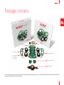
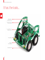
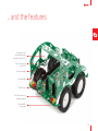
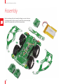
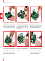
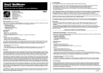
A motorized development platform
To our valued customers
I want to express my thanks to you for being interested in our products and for having confidence in
MikroElektronika.
The primary aim of our company is to design and produce high quality electronic products and to
constantly improve the performance thereof in order to better suit your needs.
We hope you’ll have great fun with the Buggy, and that it’ll be a great learning experience as well.
Nebojsa Matic,
Owner and General Manager
of MikroElektronika
Table of contents
Introduction
6
Motors
20
Package contains
7
Power supply
21
It has the look and the features
8
mikroBUS™ sockets
22
Assembling
10
click™ boards
23
Choose your driver
17
Firmware
24
clicker 2 & mikromedia pinout
18
Android app
24
clicker 2 – a click™ board two-seater
19
Schematic
25
Lights
20
What’s Next?
26
5
A motorized development platform
Introduction
For years we have been honing our expertise in designing
powerful and easy to use hardware development tools. Our
reputation was forged, in part, on our range of mikromedia
boards and the ever-growing line of click™ boards. This time,
we’ve put all that experience to use, and put it on wheels —
the Buggy is a four-wheel robotics workstation that takes
advantage of all the innovations we came up with in
recent years: it employs a clicker 2 / mikromedia pinout that
makes it compatible with a wide range of microcontroller
architectures. Then we added mikroBUS™ sockets giving
you the choice of over 100 click™ boards to enhance the
four-wheeler and make it your own with various sensors and
communication boards. We also published a free Android App
for remotely controlling the Buggy and we made the code
available to you. Finally, we took great care to provide you with
the relevant documentation to make it easy to start working
on your Buggy projects right away. Hence this manual. Enjoy.
Open source
Android App to
jump-start your
development
42 mm
1 653.54 mils
61 mm
2 401.57 mils
139 mm
5 472.44 mils
Package dimensions:
L 277mm, W 232mm, H 56mm
Three additional
click™ board sockets,
additional outputs,
mounting holes
Four-wheel
clicker 2 or
mikromedia
workstation
Package weight:
~800-850g
Power supply
3.7V, 2000mAh LiPo battery
6
108.5 mm
4 271.65 mils
84 mm
3 307.08 mils
Package contains
hoizontal bar
2 x side panels
LiPo
battery
4 x removable wheels
the main panel
with circuitry,
motors, lights
3 x mikroBUS™ plates
Mini USB cable
The kit contains 1) the main panel with circuitry, motors, lights, and the mikromedia connector; 2) a pair of battery holder tabs; 3) two side panels and a horizontal
bar; 4) three mikroBUS™ plates; and 5) four wheels.
7
A motorized development platform
It has the looks...
Multiple slots for
soldering t he top bar
Top bar with mounting
holes for antennas
Two mikroBUS™ socket
plates on the front
Front signal light
Front (main
beam) headlight
Removable wheels
8
... and the features
Analog input screw
t erminals (shared with
mikroBUS™ sockets 2 & 3)
Power screw terminal
(5 and 3.3V)
Rear and stop light
Rear signal light
ON/OFF switch
Mini USB connector for
charging the battery
Rear mikroBUS™
socket plate
9
A motorized development platform
Assembly
With basic soldering skills you’ll assemble the Buggy in no time. Check out
the “package contains” section on page 7 to make sure you have everything
prepared. Then proceed with step 1 and all the way through.
10
STEP 1 - Remove wheels from one side
STEP 2 - Connect the battery
STEP 3 - Insert the battery
The Buggy’s main board is packed in the box with
wheels attached. Remove both wheels from the
left side of the board, by pulling on them.
Pull the battery wire under the rail and attach it
to the battery connector.
Push the whole battery under the rail. Be careful not
to pinch the wire. The battery should fit squarely
between Buggy’s four motors.
STEP 4 - Insert battery holder tabs
STEP 5 - Solder battery holder tabs
STEP 6 - Reattach the wheels
Look for the two smallest pieces of PCB in the
box. Those are the supporting tabs that keep the
battery in place. Pick either one and place it in the
sockets on either side of the board, so that the
curved side is facing outwards
Hold the battery-holder tab and flip the
main board so that the battery is now facing
downwards. Solder the tab. Repeat step 4 and 5
for the second battery-holder tab.
The axle and the socket on the wheel are not
completely round, so be careful to correctly align
them before pushing the wheel towards the axle.
11
A motorized development platform
STEP 7 - Insert mikroBUS™ socket plates
STEP 8 - Solder mikroBUS™ socket plates
STEP 9 - Set side panels in place
The Buggy comes with three additional
mikroBUS™ socket plates. Pick either one and slip
it inside one of the three slits on the main board,
marked mikroBUS 1, mikroBUS 2, and mikroBUS 3.
While holding the mikroBUS™ socket plate inside
the slit with your finger, flip the Buggy. Solder
the plates, making sure to cover each of the eight
contact points. Repeat steps 7 and 8 for the
remaining two plates.
Next, position the two side panels. You won’t be
soldering them yet, but pay attention to place the
panels in the correct direction: the lower part faces
forward, where the white and yellow LEDs are.
STEP 10 - Attach top bar
STEP 11 - Solder top bar
STEP 12 - Solder side panels
The top bar connects the two side panels and
keeps the Buggy rigid, while also providing slots for
soldering additional electronics. Notice that each
side panel has four different slots for placing the
top bar. You can use whichever one suits you best.
Solder the top bar to each side panel. You can
always unsolder it later if you’d like to to change
its position.
With the top bar soldered, flip the Buggy. Solder
the two side panels to the main board; there are
two contact points for each panel, one in each
corner of the main board. Now flip the Buggy back
on its wheels. You’re done assembling!
12
www.mikroe.com/buggy
A motorized development platform
www.mikroe.com/buggy
Choose your driver
Now that you’ve assembled the Buggy, the only remaining thing is to put a microcontroller in the driver’s seat. You have two types of choices: (1) clicker 2 is a
compact development platform with a MCU and two mikroBUS™ sockets (2) mikromedia is a multimedia development system with a 320x240 TFT touchscreen and
a rich set of onboard modules. Both of these boards are available for different microcontroller architectures.
clicker 2
mikromedia
click™
board
If you want to remotely
control your Buggy, you’ll
also need a communications
click™ board with a wireless
transceiver module (Wi-Fi or
Bluetooth work well).
17
A motorized development platform
Not connected
Reference Ground
Not connected
Left side motors control
Pin functions
Right side motors control
mikroBUS 1 PWM pin
mikroBUS 2 PWM pin
mikroBUS 3 PWM pin
Brake lights
Right signal lights
Low intensity lights
mikroBUS 3 CS pin
mikroBUS 3 RST pin
main beam headlights
Not connected
RX
TX
SCL
I2C Lines
SDA
3.3V power supply
Reference Ground
UART Lines
18
NC
GND
NC
NC
PWM-A
PWM-B
PWM-C
PWM-D
PWM1
PWM2
PWM3
BRAKE
TURN-R
H.LAMPS
CS3
RST3
M.BEAM
NC
NC
NC
UART
UART
I2C
I2C
3.3V
GND
5V
GND
AN1
AN2
AN3
BAT-VSENSE
CS2
RST2
TURN-L
INT1
INT2
INT3
BAT-STAT
VBUS
NC
NC
NC
NC
NC
RST1
CS1
SPI
SPI
SPI
3.3V
GND
System power supply
Reference Ground
mikroBUS 1 AN pin
mikroBUS 2 AN pin
mikroBUS 3 AN pin
battery sensing pin
mikroBUS 2 CS pin
mikroBUS 2 RST pin
left signal light
mikroBUS 1 INT pin
mikroBUS 2 INT pin
mikroBUS 3 INT pin
battery charging status
USB power supply
Not connected
mikroBUS 1 RST pin
mikroBUS 1 CS pin
SCK
SPI Lines
MISO
MOSI
3.3V power supply
Reference Ground
Pin functions
clicker 2 & mikromedia pinout
The Buggy carries a standard clicker 2/mikromedia
pinout with a pair of 1x26
connection pads. However,
to make the Buggy easier
to program, some of the
pins have descriptive labels
that point out their functions in relations to the motors, lights and so on.
clicker 2 – a click™ board two-seater
Available for several MCU architectures, clicker 2 is a compact development kit with two mikroBUS™ sockets for click™ board connectivity. You can use it to quickly
build your own gadgets with unique functionalities and features. It’s an ideal Buggy driver because it lets you leverage the huge potential of click™ boards, our
constantly expanding range of over 100 add-on boards.
19
A motorized development platform
Lights
Motors
VCC-5V
D3
PMEG3010ER
Just like a real car, the Buggy has a set
of front and rear lights for signaling and
for lighting the way. These lights are
routed in a way that makes them easier
to program should you develop your own
firmware for the Buggy. They’re grouped
in three sets based on function: (1)
The pair of white LEDs on the front are
headlights, with two modes of brightness;
(2) The red LED brake lights on the rear
also have two brightness levels; and (3)
the two pair of yellow LED signal lights
are grouped by left and right side.
Highlighted above are the five pins that
control the lights. TURN L and TURN R
regulate the signal lights. H.LAMPS turns
on the headlights and rear lights at low
intensity. Activate both the M.BEAM and
VCC
TURN_L
BRAKE
TURN_R
HEADLAMPS
MAIN BEAM
HDR2
FL
VCC
LDY
RL
LDR
2
2
1
VCC
LDW
VCC
PWM-C and
PWM-D
pins control
the right
side motors
PWM-A
and PWM-B
pins control
the left
side motors
0
REAR LEFT LIGHTS
VCC
VCC
FR
LDY
VCC
LDR
VCC
RR
LDY
2
2
1
1
0
0
VCC
REAR RIGHT LIGHTS
FRONT RIGHT LIGHTS
LED schematics
20
U6
1
0
FRONT LEFT LIGHTS
VCC
U7
H.LAMPS at the same time for brighter
headlights. For brighter rear lights (stop
lights), activate the BRAKE and H.LAMPS
at the same time.
VCC
LDW
HDR1
Pins for controling Buggy’s light
VCC
LDY
The Buggy has a differential motor drive. The four DC motors
are split by left and right axis (controlled by DRV833RTY motor
drivers, U6 and U7, one for each side). Steering takes place when
you vary the relative rate of rotation between the left and right
side. This type of steering is simpler to manipulate if you’ll be
writing your own firmware for the Buggy. Also, when one pair
of wheels is put in reverse while the other is in normal gear, the
Buggy will start to spin, which wouldn’t be possible otherwise.
To prevent the motors from drawing too much current from the
battery (and in doing so prevent the other components from
functioning properly) a few resistors are placed to limit current
draw. Each motor can draw a maximum of 400 mA, for a total of
1.6 A for all four motors.
Power supply
Battery charger
Screw teminals
ON/OFF switch
The Buggy runs on a 3.7V 2000mA battery.
Once you install the battery, there’s no need to
take it out; charge it through the Buggy’s USB
port. A miniature single-cell, fully integrated LiIon, Li-Polymer charge management controller.
MCP73832 enables that. A red power indication
LED will signalize when the battery is charging.
Once charged, it’ll turn off.
The Buggy’s expandability is not limited to
mikroBUS™ sockets and click™ boards. You can
attach a variety of sensors and antennas to its
top bar. A pair of screw terminals will allow you
to connect those additional components to the
main power supply. Both 3.3V and 5V outputs
are available. There’s an additional pair of screw
terminals that are analog inputs.
The ON/OFF switch on the rear of the Buggy,
between the USB port and the left rear lights,
controls the main power supply. A clicker 2 board
also has its own ON/OFF switch, which should
be kept in the ON position in order for the main
power supply switch to work. A green LED will
indicate the presence of a power supply. When
removing the clicker 2, keep both switches OFF.
21
A motorized development platform
VCC-3.3V
mikroBUS sockets
AN-MB
RST-MB
CS-MB
SPI-SCK
SPI-MISO
SPI-MOSI
22
AN-MB
CS-MB
I2C-SDA
I2C-SCL
INT-MB
PWM-MB
14
13
12
11
10
AN-MB
CS-MB
I2C-SDA
I2C-SCL
INT-MB
PWM-MB
15
14
13
12
11
10
9
2
3
4
5
6
7
8
SPI-SCK
SPI-MOSI
SPI-MISO
UART-TX
UART-RX
16
PWM-MB
INT-MB
UART-RX
UART-TX
I2C-SCL
I2C-SDA
PWM
INT
RX
TX
SCL
SDA
5V
GND
VCC-5V
VmBUS HEADER
(H1/H2/H3)
VCC-5V
Vertical mikroBUS™ socket schematic
VmBUS HEADER
(H1/H2/H3)
3
4
5
6
7
SPI-MOSI
SPI-MISO
UART-TX
UART-RX
8
2
Learn more about the mikroBUS™ standard at www.mikroe.com/mikrobus
1
Front mikroBUS™ plates
15
16
VCC-3.3V
PWM-MB
INT-MB
UART-RX
UART-TX
I2C-SCL
I2C-SDA
PWM
INT
RX
TX
SCL
SDA
5V
GND
1
AN
RST
CS
SCK
MISO
MOSI
3.3V
GND
9
AN-MB
RST-MB
CS-MB
SPI-SCK
SPI-MISO
SPI-MOSI
RST-MB
The Buggy comes with three mikroBUS™ sockets, two in the front, one in
the rear. If you connect a clicker 2 board to the Buggy you’ll get two more
sockets for a total o five mikroBUS™ sockets.
There are more than a 100 click™ boards available. Each click™ board comes
with a single module, and these vary from sensors to displays, audio to motor
control, communication to fiber optics, even speech recognition.
VCC-3.3V
VCC-5V
SPI-SCK
mikroBUS is a specially designed pinout standard with SPI, I2C, Analog,
UART, Interrupt, PWM, Reset and Power supply pins. It has two 1x8 headers,
each with VCC and GND power supply pads.
™
VCC-3.3V
AN
RST
CS
SCK
MISO
MOSI
3.3V
GND
RST-MB
™
Enhancing the Buggy with various sensors and communication modules
is easy — you just plug a MikroElektronika click™ board into one of the 3+2
available mikroBUS™ sockets and you’re good to go.
VCC-5V
Rear mikroBUS™ plate
click™ boards are plug-and-play!
For a few years now, MikroElektronika has been expanding
their range of click™ boards. Almost each month several
new click™ boards are released, carrying all types of
sensors and communication modules. There are over a
100 click™ boards to choose from. You’ll be able to expand
your Buggy with additional functionality with literally
zero hardware configuration. Just plug and play.
For the complete list of available click™ boards, please visit:
www.mikroe.com/click
BLE P click™
BlueTooth click™
GPS click™
WiFi PLUS click™
GSM click™
microSD click™
MPU 9DOF click™
nRF C click™
Proximity click™
BUZZ click™
23
A motorized development platform
Firmware
Android application
If your clicker 2 board came with the Buggy as
part of a kit, then you’re all set — the firmware
compatible with the Android app shown on the
right is already installed.
If you’ve purchased only the Buggy by itself, no
problem. Clicker 2 and mikromedia boards have a
USB-HID bootloader which makes it easy to install
the firmware. All you have to do is download the
mikroBootloader application for your clicker 2 or
mikromedia board, along with the firmware, all
available from www.mikroe.com/buggy.
A free open-source Android App for driving the
Buggy is available from mikroe.com/buggy. The App
talks to the Buggy through a wireless transceiver
click™ board (Bluetooth or Wi-Fi). It’s a great starting
point to develop your own original applications for
the Buggy, just open the project in your Android
SDK of choice (for example Android Studio, shown
here). But first, spend some time driving the Buggy
around from your smartphone or tablet, just for fun.
Edit the code for the Buggy App and make it
your own — shown here is Android Studio, a
popular Android platform IDE
mikrobootloader application
Then turn off the Buggy, detach the clicker 2
board, plug it to your computer via USB, and follow
the simple 4-step procedure in mikroBootloader.
If you’re making your own custom firmware for the
Buggy in mikroC™, mikroBasic™ or mikroPascal™,
you’ll also upload it with the mikroBootloader.
24
Install the app on your smartphone or tablet
and take your Buggy to the road
Schematic
L2
1.5uH
U2
Vbat
VIN
10 PWM-MB2
VCC-5V
H1
16PIN HOLDER
H2
16PIN HOLDER
UART-TX
UART-RX
11 INT-MB3
10 PWM-MB3
8
SPI-MISO 5
12 I2C-SCL
7
SPI-MOSI 4
13 I2C-SDA
6
2
15 AN-MB3
3
1
RST-MB2
SPI-SCK
16
7
UART-RX
8
6
SPI-MOSI 4
14 CS-MB3
2
1
3
PWR-EN
BAT-VSENSE
R4
100K
C1
R54
100K
VCC-3.3V
J1A
M2
DMP2305U
R51
100K
VCC-5V
9
100pF
11 INT-MB2
VCC-3.3V
C141
12 I2C-SCL
C140
15 AN-MB2
100nF 10nF
13 I2C-SDA
C79
1uF
14 CS-MB2
C72
22uF
16
C68
22uF
9
C67
22uF
10 PWM-MB1
C66
10pF
1
R49
100K
CN5
R45
10K
C70
SPI-MISO 5
R11
15K
R43
1K
C71
100nF
14 CS-MB1
TPS63060
VIN
12 I2C-SCL
C69
22uF
13 I2C-SDA
D1
PMEG3010ER
100K
VCC-5V
R41
100K
UART-TX
R46
R10
8K2
USB-VBUS
10
9
8
7
6
11 INT-MB1
R7
10K
2
R9
100K
USB MINIB
E8
10uF
16
VCC-IN
E7
10uF
L1
L2
VIN
VOUT
EN PGND FB
PS
GND
PG
VAUX
3
VBUS
DD+
ID
GND
1
2
3
4
5
VIN
PWR-EN
RST-MB1
FP1
1
2
3
4
5
15 AN-MB1
Vusb_IN
SPI-SCK
CN4
1uF
SW1
JS202011AQN
VCC-IN
VCC-IN
3.3V VOLTAGE REGULATOR
R62
3K9
C3
100nF
R2
5K6
C80
2.2uF
H3
16PIN HOLDER
R5
470
PMEG3010ER
C4
100nF
R6
12K
VCC-IN
VCC-5V
VCC-5V
8
E4
10uF
7
Charging Current approx. 250mA
C5
22uF
6
E2
10uF
MCP73832
Q8
BC846
VCC-3.3V
R1
82K
UART-RX
VCC-5V
4
SPI-MISO 5
VCC-IN
5
STAT PROG
VSS
VBAT VDD
UART-TX
E1
10uF
R56
10K
BAT-STAT
U11
SPI-MOSI 4
1
2
3
POWER
3
R59
2K2
VCC-3.3V
LD1
D2
2
R61
10K
GND
1
R60
10K
VCC-3.3V
U1
MCP1826
RST-MB3
E10 10uF
Q2
BC846
VCC-5V
Vbat
SPI-SCK
VCC-IN
9
6
R58
10K
Q1
BC846
SHDN
VIN
GND
VOUT
ADJ
LD2
1
2
3
4
5
R57
2K2
CHARGE
VCC-3.3V
CN1
Vbat
C27
22uF
VCC- 3.3V
Vbat
AN-MB3
C28
100nF
R3
10K
AN-MB2
R2
Q6
PDTC114EU
2
R1
Q5
PDTC114EU
3
H9
MOTOR_HLD_PADS
3
2
16
15
14
13
5
6
7
8
R39
0.5
GND
Vbat
VINT
GND
VM
VCP
12
11
10
9
C33
10nF
C34
2.2uF
UART-RX
UART-TX
I2C-SCL
I2C-SDA
RX
TX
SCL
SDA
VCC-3.3V
VCC- IN
HDR2
1
R1
LIGHTS HOLDER
R33
1K
R2
Q4
PDTC114EU
AN
TURN_R
2
1
0
1
R1
R2
INT
HEADLAMPS
Q3
PDTC114EU
1
VCC-3.3V
BRAKE
REAR
RIGHT
R1
R8
1K
Q9
PDTC114EU
SCK
SDI
SDO
RR
LIGHTS HOLDER
R30
2K2
R2
RST-MB1
CS-MB1
SPI-SCK
SPI-MISO
SPI-MOSI
LEFT
0
1
3
R38
0.5
AISEN
AOUT2
BOUT2
BISEN
AOUT1
nSLEEP
AIN1
AIN2
1
2
3
4
BOUT1
nFAULT
BIN1
BIN2
1
4
1
4
4
1
U7
DRV8833RTY
1
H11
MOTOR_HLD_PADS
M
MOTOR
REAR
LEFT
(RL)
2
2
3
M
4
MOTOR
FRONT
LEFT
(FL)
2
3
PWM
PWM-A
PWM-B
VCC- 3.3V
RL
1
2
PWM-A
PWM-B
PWM-C
PWM-D
PWM-MB1
PWM-MB2
PWM-MB3
BRAKE
TURN_R
HEADLAMPS
CS-MB3
RST-MB3
MAIN BEAM
2
2
C32
100nF
R37
10K
TURN_L
AN-MB1
AN-MB2
AN-MB3
BAT-VSENSE
CS-MB2
RST-MB2
TURN_L
INT-MB1
INT-MB2
INT-MB3
BAT-STAT
USB-VBUS
FRONT
RIGHT
LIGHTS HOLDER
R32
1K
R2
2
C31
22uF
Vbat
FR
1
R1
R2
HDR1
2
16
15
14
13
5
6
7
8
2
2
0
1
D3
PMEG3010ER
VCC- 3.3V
LEFT
LIGHTS HOLDER
R31
2K2
3
C30
2.2uF
R1
3
MAIN BEAM 1
VCC-5V
Vbat
FL
1
0
VCC- 5V
3
2
2
12
11
10
9
Q7
PDTC114EU
3
R36
0.5
GND
VINT
GND
VM
VCP
VCC-3.3V
R34
220
C29
10nF
3
R35
0.5
H5
MOTOR_HLD_PADS
AISEN
AOUT2
BOUT2
BISEN
CN2
Vbat
3
1
2
3
4
AOUT1
nSLEEP
AIN1
AIN2
U6
DRV8833RTY
BOUT1
nFAULT
BIN1
BIN2
4
1
4
1
1
4
M
2
MOTOR
FRONT
RIGHT
(FR)
2
3
H4
MOTOR_HLD_PADS
3
4
M
1
MOTOR
REAR
RIGHT
(RR)
2
3
CN3
PWM-D
PWM-C
Vbat
25
A motorized development platform
What’s Next?
You have now completed the journey through each and every feature of the Buggy.You got to know its features, supported microcontrollers and other
expandability options. Now you are ready to start building your own robotic vehichle. We are suggesting several steps which are probably the best way to
begin. We invite you to join our community. You will find very useful projects and tutorials and can get help from a large ecosystem of users. Welcome!
1
2
3
You still don’t have an appropriate compiler? Locate
the compiler that suits you best on our website
(see link below).
If you want to find answers to your questions on many
interesting topics we invite you to visit our forum at
www.mikroe.com/forum and browse through
more than 150 thousand posts. You are likely to
find just the right information. On the other hand,
if you want to download free projects and libraries,
or share your own code, please visit the Libstock™
website. With user profiles, you can get to know
other programmers, and subscribe to receive
notifications on their code.
We all know how important it is to be able to rely on
someone in moments when we are stuck with our
projects, facing a deadline, or when we just want
to ask a simple, basic question that’s pulling us
back for a while. We do understand how important
this is to people; our Support Department is one
of the pillars upon which our company is based.
MikroElektronika offers Free Tech Support to
the end of product lifetime, so if something goes
wrong, we are ready and willing to help!
Compilers
Choose between mikroC™, mikroBasic™ and
mikroPascal™, and download a fully functional
demo version, so you can begin building your
applications.
www.mikroe.com/compilers
26
Community
www.libstock.com
Support
www.mikroe.com/support
DISCLAIMER
All the products owned by MikroElektronika are protected by copyright law and international copyright treaty. Therefore, this manual is to be treated as any
other copyright material. No part of this manual, including product and software described herein, may be reproduced, stored in a retrieval system, translated or
transmitted in any form or by any means, without the prior written permission of MikroElektronika. The manual PDF edition can be printed for private or local use,
but not for distribution. Any modification of this manual is prohibited.
MikroElektronika provides this manual ‘as is’ without warranty of any kind, either expressed or implied, including, but not limited to, the implied warranties or
conditions of merchantability or fitness for a particular purpose.
MikroElektronika shall assume no responsibility or liability for any errors, omissions and inaccuracies that may appear in this manual. In no event shall MikroElektronika,
its directors, officers, employees or distributors be liable for any indirect, specific, incidental or consequential damages (including damages for loss of business profits
and business information, business interruption or any other pecuniary loss) arising out of the use of this manual or product, even if MikroElektronika has been advised
of the possibility of such damages. MikroElektronika reserves the right to change information contained in this manual at any time without prior notice, if necessary.
HIGH RISK ACTIVITIES
The products of MikroElektronika are not fault – tolerant nor designed, manufactured or intended for use or resale as on – line control equipment in
hazardous environments requiring fail – safe performance, such as in the operation of nuclear facilities, aircraft navigation or communication systems, air
traffic control, direct life support machines or weapons systems in which the failure of Software could lead directly to death, personal injury or severe
physical or environmental damage (‘High Risk Activities’). MikroElektronika and its suppliers specifically disclaim any expressed or implied warranty of
fitness for High Risk Activities.
TRADEMARKS
The MikroElektronika name and logo, mikroC™, mikroBasic™, mikroPascal™, Visual TFT™, Visual GLCD™, mikroProg™, Ready™, MINI™, mikroBUS™, EasyPIC™, EasyAVR™,
Easy8051™, click™ boards and mikromedia™ are trademarks of MikroElektronika. All other trademarks mentioned herein are property of their respective companies.
All other product and corporate names appearing in this manual may or may not be registered trademarks or copyrights of their respective companies, and are only
used for identification or explanation and to the owners’ benefit, with no intent to infringe.
Copyright © 2015 MikroElektronika. All Rights Reserved.
27
If you want to learn more about our products, please visit our website at www.mikroe.com
If you are experiencing some problems with any of our products or just need additional
information, please place your ticket at www.mikroe.com/support
If you have any questions, comments or business proposals,
do not hesitate to contact us at [email protected]
BUGGY manual
ver. 1.02
0 100000 027523