1
Camera
Installation
Dome
and Service
Manual
SpeedDome*
Camera Dome
Installation
and Service
8000-1715-01, Rev. A
WLG 1O/97
Manual
FCC COMPLIANCE
This equipment has been tested and found to comply with Part 15
of the FCC Rules. Operation is subject to the following two
conditions: 1) this device may not cause harmful interference, and
2) this device must accept any interference received, including
interference that may cause undesired operation.
EQUIPMENT MODIFICATION
CAUTION
Equipment changes or modifications not expressly approved by
Sensormatic Electronics Corporation, the party responsible for
FCC compliance, could void the user’s authority to operate the
equipment.
WARRANTY DISCLAIMER
Sensormatic Electronics Corporation makes no representation or
warranty with respect to the contents hereof and specifically
disclaims any implied warranties of merchantability or fitness for
any particular purpose. Further, Sensormatic Electronics
Corporation reserves the right to revise this publication and make
changes from time to time in the content hereof without obligation
of Sensormatic Electronics Corporation to notify any person of
such revision or changes.
LIMITED RIGHTS NOTICE
For units of the Department of Defense, all documentation and
manuals were developed at private expense and no part of it was
developed using Government Funds. The restrictions governing
the use and disclosure of technical data marked with this legend
are set forth in the definition of “limited rights” in paragraph (a)
(15) of the clause of DFARS 252.227.7013. Unpublished - rights
reserved under the Copyright Laws of the United States.
No part of this manual may be reproduced in any form without
written permission from Sensormatic Electronics Corporation.
SensorVision and SpeedDome are trademarks of Sensormatic
Electronics Corporation. Product names mentioned herein may be
trademarks or registered trademarks of other companies.
0 Copyright Sensormatic Electronics Corporation 1997.
Using this manual ........................................................................................................
1.0
1.1
1.2
1.3
1.4
INTRODUCTION
2.0
2.1
2.2
2.3
2.4
2.5
INSTALLATION..
..................................................................................................
PRE-INSTALLATION GUIDELINES.. ........................................................................
SAFETY PRECAUTIONS ...........................................................................................
INDOOR MOUNTING METHODS.. ...........................................................................
OUTDOOR MOUNTING METHODS.. .......................................................................
ADDITIONAL INFORMATION.. ................................................................................
..................................................................................................
WHAT IS SpeedDome?. ............................................................................................
SpeedDome FEATURES.. .........................................................................................
IINSTALLATION METHODS .....................................................................................
SPECIFICATIONS .....................................................................................................
v
l-l
1-l
l-2
l-6
l-8
2-l
.2-l
2-2
2-2
2-2
.2-2
Appendixes
Appendix
Appendix
A
B
American Dynamics to SpeedDome Interconnection .............................................
SensorNet and UniCard.. .........................................................................................
A-l
B-l
iii
Using
this
manual
Use this manual when installing Sensormatic SpeedDomes
for
the first time. Use it later as a guide for maintenance
and
troubleshooting.
Sections
included
in this
manual
This manual contains four sections arranged
1.0
INTRODUCTION
provides
as follows:
a product
overview
and
specifications.
20
INSTALLATION
provides background and procedures
required to install and adapt the unit to its environment.
Wuick
Reference
Guide”
The quick reference guide
portion of the Installation and Service chapters provides
procedures, wiring diagrams, and cable terminations in a
reference format. Copy appropriate pages for use in the
field.
Appendixes
contain information on attaching SpeedDome
camera domes to American
Dynamics
systems and
SensorNeWnicard
domes.
Questions?
For technical
address:
Customer
support
Engineers
or questions
call l-800-543-9740.
Dealers call l-800-442-2225
IV
that this manual
does not
Introduction
1.1
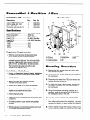
WHAT
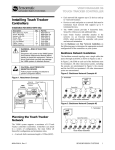
IS SpeedDome’“?
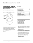
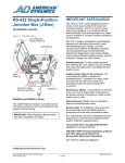
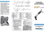
The SensorVision SpeedDome (Figure l-l) is a programmable
dome designed for retail stores, casinos, manufacturing
facilities, hotels, hospitals, and a wide variety of other facilities,
especially where appearance is an important consideration.
The SpeedDome is part of a SensorVision CCTV (Closed Circuit
Television) system, a network of remote camera devices. The
dome pans, tilts, zooms, and focuses on the subject, whether it
is in low light, moving, or at a distance.
Manual operation enables these functions to be controlled by a
host control system from a centrally located console. Automatic
operation enables the dome to store, and recall at a later time,
camera scenes or field of views (Targets/Presets) and a series
of pan/tilt/zoom movements (Patterns). SpeedDome can also
activate or respond to external security devices.
Compact,
Visible
Dome.
SpeedDome
is visually
appealing and unobtrusive. The dome chassis consists of a
carriage assembly hidden inside a protective housing with a
ceiling-mounted,
gloss black “eyeball” suspended from it. The
carriage assembly contains the dome’s power supply, a pan
motor assembly, and electronic circuitry used to operate the
dome. The eyeball, only 19cm (7.5”) in diameter, houses a
camera,
camera electronics,
lens, lens motors, and tilt
assembly.
SENSORVISION
SpeedDome
l-l
Monochrome
and Color Cameras.
The SpeedDome uses monochrome
or color cameras. Monochrome
cameras come in l/2’ CCD, EIA, 60Hz and l/2” CCD, CCIR,
50Hz versions. Color cameras come in l/2” CCD, NTSC, 60Hz
and l/2” CCD, PAL, 50Hz versions.
The color camera is fully digital, which has several advantages
over analog versions. It has no field adjustments, and better
light sensitivity (2.2 lux) and picture resolution (430 TV lines) due
to Digital Signal Processing (DSP).
Camera
Lens.
The indoor version uses a motorized 880mm, fl.2 lens; the outdoor version uses an &80mm, fl.2 lens
or an fl.8, 12-120mm lens. The lens and associated electronics
provide a totally unique Iris Preferencel
that automatically
adapts the picture to even the most difficult lighting conditions
(see “Iris Preference’“” under features).
Camera/Lens
Concealment.
For indoor versions, a
clear, acrylic “contact lens” mounts flush with the contour of the
eyeball to prevent detection of the camera’s viewing position.
For indoor versions, outer acrylic bubbles, available in clear,
tinted, gold, or mirrored finishes further conceal the camera’s
viewing position or customize its appearance
to blend with
special decors.
1.2
SpeedDome
Performance
In alphabetical
l
l
1-2
FEATURES
Features
order:
Alarm inputs and outputs.
The SpeedDome accepts
dry-contact
switch closures from four different sensing
devices. This or any other system camera can then be
programmed to scan or position itself to observe alarms and
events. Onboard outputs enable the SpeedDome to control
other activities such as turning on lights or initiating sound
messages.
Apple
Peel Default
Pattern.
When no programmed
patterns are entered into its software, the SpeedDome automatically defaults to an “apple peel” pattern. It initially aims
along the ceiling and then performs 360” pans: 3 for the
indoor mount and 3 for the outdoor mount, dropping 30”
after each pan.
SENSORVISION SpeedDome
Introduction
SENSORVISION SpeedDome
1-3
Automatic
Calibration.
When power is first applied, the
SpeedDome
calibrates its position-sensing
electronics by
going through a one-minute motion routine (during which it
ignores commands).
Automatic
Lens Control
(AN).
Also called auto-iris,
this feature enables the lens iris to adjust to different lighting
conditions automatically;
however, it can be overridden at
the console to adjust lighting manually. See ‘Iris Preference ’
in this section.
.
Automatic/Manual
Dome
Reset.
A watchdog circuit
automatically
resets
the dome
if preprogrammed
instructions are incorrect. The dome can be manually reset
using keyboard commands from the console as long as the
dome can communicate.
Automatic
Synchronization.
The dome automatically
synchronizes to a 50 or 60Hz ac source, free-runs on its
own internally generated
clock, or synchronizes
to an
external frequency generator su;h as a Genlock.
Auto-Repeat
“taught”
zoom-in
pattern
will run
Surveillance
Pattern.
The dome can be
to continuously
pan any designated
area and to
for close-ups
as it pans. Once activated,
the
repeats only if it is commanded to do so; the pattern
only once.
Backup
Power.
Depending
on the dome’s processing
requirements, the backup power will maintain memory for at
least a 24-hour time period.
ClearVIew”.
The outdoor SpeedDome is equipped with a
unique heater and air circulation system that keeps the
outer lens clear of ice and fog in any weather condition.
DSP Motor
Control.
All lens motors are assembled on a
balanced mechanism that supports high-speed pan and tilt
movements.
Digital signal processing (DSP) and dynamic
motor braking ensure precise and fluid camera movement
and dramatically extend motor life.
High-Resolution
Color
Camera.
This digital camera
delivers superb picture clarity and vivid colors. A highresolution monochrome camera is also available.
Iris
Preference”.
This feature enables the operator to
manually adjust backlighting beyond the adjustments made
by the ALC for precise and accurate illumination of the
subject. Iris Preference combines the flexibility of manual iris
with the benefits of auto iris.
1-4
SENSORVISION
Sp?edDOme
introduction
l
l
l
l
l
l
l
Pattern
Speed
Multiplier.
With the VMl system, the
operator can multiply the base pattern speed range of the
camera (3 -24” per second depending on zoom position) by
two (6-48”) three (g-72”) or four times (12-96”). All other
host systems have fully proportional pan (&90”/sec) and tilt
(0-50”lsec).
Transient
Protection.
All dome inputs and outputs are
opto-coupled,
transformer isolated, or provided with heavy
duty transient protection to enhance long-term product reliability. The outdoor dome also has lightning strike protection.
Target
(Preset).
The SpeedDome can precisely pan, tilt,
zoom, and focus in on an alarm-triggered event in less than
one second. This speed and accuracy enables a single
SpeedDome
to offer better coverage than multiple fixed
cameras.
Switching
Power
Supply.
Compared
to previous
domes, this circuit reduces power consumption by 60 percent and enables cable runs of up to 120 meters.
Zoom
Adjusted
Program
(ZAP)“.
The ZAP feature
automatically adjusts pan and tilt speeds during manual
operation to keep the video image constant as the camera
lens adjusts from wide to telescopic. For example, a 10x
lens panning at 24” per second at wide angle slows to 3”
per second at full zoom. Programming or running a pattern
disables ZAP.
180” Flip’“. The dome can enhance the tracking of a target
as it moves toward the camera, directly beneath it, and
away from it by flipping its camera 180” (hence, turning the
video image right-side-up)
at the point where the target
passes directly beneath the dome.
10X “Fast”
Lens. A 8-80mm, fl.2 lens or 12-120mm
(outdoor), fl.8 lens is provided. The video image from the 880mm lens fills the monitor screen at 30 meters (700’); the
video image from the 12-l 20mm lens fills the monitor screen
at 45 meters (750’).
SENSORVISION
SjXed~OfF?t?
1-5
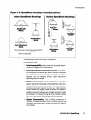
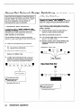
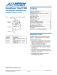
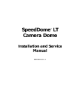
1.3,
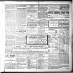
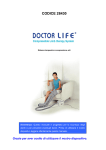
Installation
Indoor and outdoor
ure l-2).
Indoor
Methods.
domes can mount in a variety of ways (Fig-
domes.
For “drop tile” ceilings,
available that fits standard 2 x 2 openings.
a dome housing
is
For sheet rock, wood, or ceilings with special finishes, a hard
ceiling housing is available. The 20mm lip of this housing enhances the appearance of the dome in well designed ceilings.
For indoor ceilings of 6m or more, a 38mm pipe is added to the
hard ceiling mount to form a pendant mount. The pipe and
housing are matte white, but can be painted to match decor.
Outdoor
domes.
Outdoor domes are furnished with mounts
for poles or for the sides of buildings. The most popular is an
over-the-roof
design that mounts to the parapet. This mount
offers two advantages:
1) the dome can look over the roof as
well as at the area around the building, and 2) the mount
enables the dome to swing in so it can be serviced from the
roof, eliminating the need for an expensive mechanical lift.
All mounts facilitate quick installation after site
enabling wiring to be done during rough building
Once the CCTV system is turned on, the domes
quickly installed to monitor the move-in and set-up
1-6
SENSORVISION SpeedDome
preparation,
construction.
can then be
of the facility.
Introduction
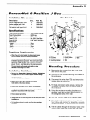
Figure
l-2.
Indoor
SpeedDome
housings-mounting
SpeedDome
Mountings
options
Outdoor
SpeedDome
h
Mountings
Over Root
Mount
RHORM
.
Pendant Mount
RHIPM
Wall Mount
RHOWM *
f--b
Hard Ceiling Mount
RHICM
* Note: There is also a corner mount adapter (RH170)
that can be added to RHOWM to mount on the
corner of a building wall.
Installation
In alphabetical
l
and Service
Pole Mount
RHOPM
Celling Mount
RHOCM
Features
order:
Interchangeability.
nected and plugged
l
Internationally
l
Safety.
l
Simple
Each dome can be easily disconinto a new location.
Recognized
Connectors.
Internationally recognized connectors are used to connect composite
and video cables from the controller to the dome. The dome
address
can be changed
without
cable disconnect
(powering down the dome).
The SpeedDome meets all international regulatory
agency standards. Electrically, all SpeedDomes
utilize lowvoltage Class 2 circuitry and cable connectors keyed to
eliminate
electrical
hazards during use. Mechanically,
indoor domes use safety chains to anchor the dome to
building structural members and a safety lanyard to retain
the chassis in its housing during servicing. Outdoor domes
also use guide wires to maintain their structural integrity.
Disassembly.
Only a Phillips screwdriver
is
required to disassemble each motor (2 screws), the slip ring
(2 screws), the camera (four screws), and each PC board (2
to 4 screws).
SENSORVISION SpeedDome
1-7
1.4
l
Snap-Hinge
l
V-Lock
Chassis.
Two sets of spring-loaded
locking
pins enable the light weight camera chassis to swing out of
its housing for servicing or to be removed entirely.
Adjustment.
The SpeedDome
eliminaies old
cumbersome
V-lock procedures
via a remote V-lock
adjustment that enables synchronization
to the ac power
line by one person at the control console.
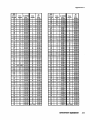
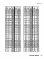
SPECIFICATIONS
See the following pages.
l-8
SENSORVISION SpeedDome
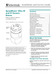
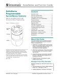
Indoor
SpeedDome
Specifications
Monochrome
(RAS585)lColor
(RAS586)
U.S. Customary
measurements
in italics are rounded
off.
I
Operational
Pan/Tilt
.__._
- ...............
.._._.~.~
.. 3” to 24” per second
(based on zoom position)
Pan Speed Multiplier:. ......-.-.-.. 2X, 3X, 4X
PanTravel: ..............
.._.~.~.~....................~.~.
360”
Tilt Travel: -._.........._._._._.................-.-.-.
>90”
.._._.~.~.
f.5”
Pan/Tilt Accuracy: ..............
Zoom/ Focus Accuracy: ...... f.5%
Camouflage
Lens
0.5f
- Density: ...........
..__.I...........-~.
._-...........
- QuickView’“Time:
._.__________________
cl sec.
Auto Synchronization
- External: ....-.................
I ._._.......................
4/p-p composite sync/220Q
- Line Locked: ..............
.._._
...................
Remote V-phase adjustment
Built-in sync generator
- Internal:
......................
>24 hours
Memory Backup: ...._._
Address Range: ...._._
.....................
..~ l-99
Programmable
Targets: ..........
See System Data Sheet
Programmable
Patterns: ......
. 3
.._._....................
4 dry contacts/3.5mA
sink
Alarm Inputs: ................
Alarm Outputs: .......
..-.-.-.-........-.....- 4 open collector drivers
@ 12Vdc, 40mA
I
Speed:
Pendant
Mount
STD PIPE l-112’ 4
- RHIPM
F
MAX 6.lm
j
(20’).
1
I
202mm
EYEBALL DIA.
190mm (7.5’)
(8’)
t
356mm (14 7
2x2 Drop
Tile Ceiling
*
607mm
I
-T102mm
Mount
(4’)
- RHlW2
Electrical
Primary Source:
Power Consumption:
Power On
In-Rush Current:
Surge Protection
- Video Output:
- Power Line:
- Sync Input:
- RS422 Comm. Line: - SensorNet Comm.
Line: --___l_-Alarm
I
Mechanical
Inputs:
16 to 36Vac, 50l60Hz
20W max.
4A for 112 cycle
1 OOA
1200A
Opto-isolated
1 OOA
Isolation
coupled
100A
Hard
transformer
Ceiling
Mount
c
- RHICM
OPTIONAL
t
2OOmm (8’)
Regulatory
I
Emissions:
Safety: .
I
FCC Part 15, Subpart
Class A
CISPR 22, Class B
B,
ETL listed as:
UL1950, UL1409
CSA 22.2 No. 205-M1983,
CSA 22.2 No. 950
EYEBALL DIA.
190mm [7.5’)
-i-
t-
394mm
(15.5 ‘)
-I
1
102mm
(4’)
Environmental
-10°C to 50°C (14“F-722°F)
Operating Temperature:
Relative Humidity: -.-.....................
0 to 95% non-condensing
SENSORVISION
SpeedDome
1-9
1
Monochrome (RAS585) / Color (RAS586), continued
n
I
Camera
Monochrome/Color
Type:
Interline transfer 1.27cm (l/2” )
CCD array
6.4 (H) x 4.8 (V) mm
2: 1 interlace
1 .OVp-p/75Q composite
48dB (typical)
Scanning Area:
Scanning System: ____
Video Out:
Signal-to-Noise:
Monochrome
only
Horizontal
Resolution:
Minimum Illumination:
AGC:
EIA
- Pickup Device: ___I
- Scanning:
- Horizontal:
- Vertical:
CCIR
- Pickup Device: ~
- Scanning:
- Horizontal:
- Vertical:
Color
500 lines at center
0.225 Iux at fl.2 (AGC on)
>24dB
Lens
Focal Length:
Aperture:
Viewing Angle
- 8mm:
- 80mm:
Field-of-View
Formulas:
6.4mm* x distance
from camera
4.8mmT x distance
682 (H) x492 (V) pixels,
525 lines, 60 fields, 30 frames
15.734kHz
59.9Hz internal sync
NTSC
- Pickup
Device:
- Scanning:
- Horizontal:
- Vertical:
PAL
- Pickup
Device:
- Scanning:
- Horizontal:
- Vertical:
l-10
SENSORVISION
from camera
(ft.)
681 (H) x 582 (V) pixels,
625 lines, 50 fields, 25 frames
15.625kHz
50Hz
430 lines at center
2.25 Iux at fl.2 (AGC on)
Through-the-lens
(TTL) Auto
Tracing White balance (ATW)
682 (H) x492 (V) pixels,
525 lines, 60 fields, 30 frames
15.734kHz
59.9Hz internal sync
681 (H) x 582 (V) pixels,
625 lines, 50 fields, 25 frames
15.625kHz
50Hz
SpeedDome
= Hor. view (ft.)
= Vert. view (ft.)
*Horizontal scanning area of pickup device in this camera.
tvertical scanning area of pickup device in this camera.
Example of a wide angle view of a 8
to 80mm lens at 3.05m (703:
6.4mm x 10 ft.
4.8mm x 10 ft.
-
(ft.)
focal length (mm)
8mm
-
..-.-..44.0”(H) x 33.3”(V)
..-...4.7”(H) x 3.5”(V)
focal length (mm)
only
Horizontal
Resolution:
Minimum Illumination:
White Balance:
8 to 80mm
f 1 .2
8mm
=
8ft. horizontal
=
6ft. vertical
view
view
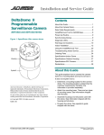
Outdoor
SpeedDome
Specifications
Monochrome
(RAS285)lColor
(RAS286)
U.S. Customary
I
measurements
off.
Operational
Pan/Tilt
Mechanical
Speed:
Pan Speed Multiplier: PanTravel:
Tilt Travel:
Pan/Tilt Accuracy:
____
Zoom/ Focus Accuracy:
Camouflage
Lens
- Density:
- QuickView’“Time:
~
Auto Synchronization
- External: ___- Line Locked:
- Internal:
Memory Backup:
Address Range:
Programmable
Targets: Programmable
Patterns: Alarm Inputs:
Alarm Outputs:
I
in italics are rounded
2” to 18” per second for
12-120mm focal length
3” to 24” per second for
8-180mm focal length
(based on zoom position)
2x, 3x, 4x
360”
SO”
lt.5”
+.5%
Over
Roof
Mount
- RHORM
2’ ST0 PIPE FITTING
0.5f
11 sec.
4Vp-p composite sync/220R
Remote V-lock adjustment
Built-in sync generator
>24 hours
1-99
See System Data Sheet
3
4 dry contactsl3.5mA
sink
4 open collector drivers
@ 12 Vdc, 40 mA
Ceiling
Mount
- RHOCM
1-W MOUNTING
Electrical
Primary Source: I .-.-.-.-.....................
21 to 36Vac, 50/60Hz
Power Consumption:
..-.. 130W max.
Surge Protection
Video Output:
_.._.............__...5,OOOA
Power Line: ._._______._________.~.~.~..
5,OOOA
Sync
Input:
Pole
Mount
- RHOPM
ROUND OR SOUARE POLE FROM
IOOmm (3.9) TO 305mm (lr)
1-W STD PIPE
..-.- .._..__..__...
-._-.-._ 5,00OA*
RS422 Comm. Line: -.... 5,000A
Alarm Inputs:
____________._._._._.~.~
5,00OA*
,,
I-1/2’STD PIPE FITTING
“Requires RS422 Surge Protector (p/n 4815-0021-01).
I
Regulatory
Emissions:
Safety:
-
FCC Part 15, Subpart
Class A
VDE 0871, Class B
CISPR 22, Class B
B,
ETL listed as:
UL1950, ULI 409
CSA 22.2 No. 205-M1983,
CSA 22.2 No. 950
CENELEC EN60950
Wall
Mount
- RHOWM
1-W
STD PIPE
,,
1-W
ST0 PIPE FITTING
395mm
(15.6’)
Optional Comer
Bracket Mount - RH170
(top view)
SENSORVISION
SpeedDome
l-11
Monochrome
n
1
(RAS285) / Color (RAS286), continued
Camera
I
Lens (with
Type: .
Scanning Area: -Scanning System: ____
Video Out:
Signal-to-Noise:
--
Horizontal
Minimum
Interline transfer 1.27cm (l/2”)
CCD array
6.4 (H) x 4.8 (V) mm
2:l interlace
1 .OVp-p/75R composite
48dB (typical)
Resolution:
Illumination:
Field=of-View
Formulas:
6.4mm* x distance
from camera
4.8mmt
x distance
-.-....430 lines at center
.-.-...2.25 lux at f1.2, (8-80mm
AGC on)
5 Iux at fl.8, (12-120mm
AGC on)
..-.-....-........-....Through-the-lens
(TTL) Auto
Tracing White balance (ATW)
NTSC
- Pickup Device: .-..............-.-.-..
682 (H) x492 (V) pixels,
- Scanning: _.___________._._.__.~........~.~.~..
525 lines, 60 fields, 30 frames
- Horizontal:
____.__.~._.__._.___....~....~.~..
15.734kHz
- Vertical: _._._________.._._._........~.~.~.~........
59.9Hz internal sync
PAL
- Pickup Device: .._._..............~.
681 (H) x 582 (V) pixels,
- Scanning: .__.__._._________._.~.~~............~.
625 lines, 50 fields, 25 frames
- Horizontal: _. .._.___._.___.........-.-.
15.625kHz
- Vertical: __.__._.__._____.___.~.~....~..~....~.~.
5OHz
SENSORVISION
Speed&me
(ft.)
= Hor. view (ft.)
= Vert. view (ft.)
*Horizontal scanning area of pickup device in this camera.
TVertical scanning area of pickup device in this
camera.
Example of a wide angle view of a 8
to 80mm lens at 3.05m (70’J:
6.4mm x 10 ft.
8mm
n
=
8ft. horizontal
=
6ft. vertical
view
view
Environmental
Operating Temperature:
Relative Humidity: ~
Storage Temperature:
Wind Loading
Wall1 Mount, Pole
Mount *, & Over-theRoof Mount with
Guidewires:
-40°C to 50°C (-40°f-1220F)
0 to 95% non-condensing
-20°C to 65°C (--4”F-149°F)
241 km/hr (150 miles/hr)
sustained winds. f. 125”
video oscillation’at
48 km/hr
(30 miles/hr) in gusting wind
Over-the-Roof
Mount without
Guidewires:
_.__.____.__________.........~.~
177 km/hr (1 10 miles/hr)
sustained winds, f. 125”
video oscillation at 24
km/hr (15 miles/hr) in
gusting wind
*Assumes
1-12
from camera
focal length (mm)
8mm
Resolution:
Illumination:
(ft.)
focal length (mm)
only
White Balance:
Lens
only
4.8mm x 10 ft.
Horizontal
Minimum
Extended
Focal Length: - 8 to 80mm _._.____________
- _._._____
12 to 12Omm
Aperture: f1.2 ._________________...~.~....~..~.~.~.~....
f1.8
Viewing Angle
Wide. . ._._._.._44.0”(H) x 33.3”(V)
..-.29.8”(H) x 22.6”(V)
Tele: -.-....-.-4.7”(H) x 3.5”(V) -...........
3.0”(H) x 2.3”(V)
500 lines at center
-........0.22 Iux at fl.2
(8-80mm, AGC on)
0.5 Iux at fl.8
(12-l 20mm, AGC on)
AGC: .._.____.___________.~..............~.~.~..............~.
>24dB
EIA
- Pickup Device: ..-.-.--............-.
682 (H) x492 (V) pixels,
- Scanning: .__._.________.___._....~...........~.
525 lines, 60 fields, 30 frames
- Horizontal: _._.___________._._.~...........~.
15.734kHz
- Vertical: ..._______._._______.....~.~.~..............
59.9Hz internal sync
CCIR
- Pickup Device:
..-.-.-..............
681 (H) x 582 (V) pixels,
- Scanning: ._____.___________._.~.~
- __________.
625 lines, 50 fields, 25 frames
- Horizontal: _._.__._________._._.~..............
15.625kHz
- Vertical: __________._
- _______.__._._._.___..........
5OHz
Color
Filter)
Long Lens
Monochrome/Color
Monochrome
Spot
mounting
on a rigid pole.
2.1
BEFORE
YOU BEGIN
2.1.1
Verifying
and Unpacking
l
l
l
l
l
l
2.1.2
Equipment
Verify that all equipment has arrived.
Verify that the unit shipped is the correct configuration for
the site.
Be organized.
Unpack components in a back room.
At the installation area, lay out parts in the order you will
need them.
Do not clutter traffic areas or cause a trip hazard.
Planning
the installation
First, carefully detail the system’s layout. Before acquiring
equipment, designate a representative to coordinate installation
planning activities. Through close interaction with the planner
and customer at the site, mark the precise locations of the
domes on a blueprint of the facility. With the blueprint, a preinstallation
site survey should be conducted
with special
installation considerations
noted.
Upon equipment
and cabling delivery to the site, review the
blueprints and site survey with the facility and loss prevention
managers. This will ensure that nothing has changed and that
everyone is in agreement with the system layout.
SENSORVISION SpeedDome
2-1
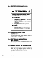
2.2
SAFETY
PRECAUTIONS
A WARNING
Observe
the following
precautions
for your
ALWAYS
l
l
l
A
common
sense
own safety:
USE:
Proper safety equipment
for the location
and type of installation.
Proper lift equipment
to reach the point
of installation.
Safety
features
of the lift equipment.
BE SURE:
l
2.3
Electrical
power is not connected to the
product during installation or to any object
that you might contact during installation.
iNDOOR MOUNTBNG
METHODS
This sub-section
consists of Quick
through Q-9 and Q-18 through Q-20.
2.4
OUTDOOR
METHODS
This sub-section
through Q-20.
2.5
Reference
Sheets
Q-l
MOUNTING
consists
ADDITIONAL
of Quick
Reference
Sheets
Q-10
INFORMATION
This chapter covers SpeedDome
installation and control via
RS422 communications.
Refer to Appendixes A and B, located
at the back of this manual, for installation
information
on
connecting SpeedDome to American Dynamics equipment, and
SpeedDome installation and control via SensorNet.
2-2
SENSORVISION SpeedDome
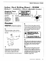
- Indoor
Method
Hard
Mount
II - Installation
Reauired
Hard bount
Ceiling
without
Parts
Kit
0351-0393-01
(part of 0200-0178-01,
ships with RHICM).
Description
“S” hook, open
Chain, Navy link
Eye bolt, IO-24 w/nut
Washer, flat, SS #lO
Nut, locking, 10x24
Aluminum tape
Qty.
2
6
1
2
1
4Fr
which
- RHICM
adjustable
bracket
FOR ALL CEILINGS
EXCEPT TILE.
A
CEILINGS
MUST BE
ABLE TO HOLD m
LEdST 9kg (20 NM)!
Part No.
2897-0004
2898-0002
2882-0112
2848-8100-l 7
2838-9154-05
3200-0115-01
i
20cn
1
037
T
3.
IMPORTANT:
template-do
Shipping box contains a
not throw the template out.
1.
Using the template, scribe a 356cm
(74”)* hole in the ceiling or tile. Cut out
the hole.
Using an S-hook, hang safety chain [d]
from a strong ceiling member and, using
a second S-hook, attach other end of the
chain to the eyebolt. Keep the chain as
taut as possible. Tighten both ends of
each S-hook.
A
KEEP CHAIN AS TAUT AS
POSSIBLE!
CLOSE ENDS OF
EACH S-HOOK!
DO NOT USE SPRINKLER
FIRE CONTROL
SYSTEM
SECURING
THE SAFETY
OR
FOR
CHAIN!
Feed video and multiconductor cables [e]
through one of the two holes in the side of
the housing. Then cover all openings in
the housing with the aluminum tape
supplied.
5.
2.
Place a washer [a] over the eyebolt
supplied [b]. Insert the eyebolt into a
hole in the top of the housing and
secure using a washer and nut [cl.
*U.S. Customary
Measurements
in italics are rounded
off.
With the three mounting tabs [f] of the
housing in the up position, insert the
housing into the ceiling hole, then from
inside the housing bring the tabs down
and tighten their screws to secure. The
housing is now ready for chassis
installation (page Q-8).
SENSORVISION
SpeedDome
Q-l
__.
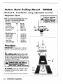
/ndoor
Hard
C&/ing
Mount
Method
2 - Installation
Required
Parts
using
- RH/CM
adjustable
Description
“s’ hook, open
Chain, Navy link
Eye bolt, lo-24 w/nut
Washer, flat, SS #lO
Nut, locking, 10x24
Aluminum tape
Qty.
2
8
1
2
1
4Ff
Part No.
2897-0004
2898-0002
2882-0112
2848-8100-17
2838-9154-05
3200-0115-01
2
2
Washer, flat #lO
Nut, wing 1 O-32
Screw, 10-32x314
Spacer, Nylon
Adapter plate
Screw, math. M8x12
0500-3439-01
0500-3440-01
8
8
2
18
1
4
FOR ALL CEILINGS
EXCEPT TILE.
CEILINGS
MUST BE
ABLE TO HOLD AT
LFAST 9kg (20 Ibs)!
I
+
0351-0394-01
components:
Support, L-shape
Support, Z-shape
bracket
A
RHICM is an ordering vehicle for 01 RHICM, which contains:
0351-0394-01 - (major components listed below)
0200-0178-01 - Indoor Hard Mount; also includes:
0351-0393-01 - Hard Mount Install Kit:
__.________._
-._.________
2848-830 1 -23
2834-0007-01
2804-7931-05
311 O-0018
0500-3982-01
5801-4074-311
39.4cm
(15.53
MAX
+
__._._.___._....__......~......~......................................~~...-.~-.---~.......~........~.~.~.---.......-.--.......~--~~
Procedure
IMPORTANT:
template-do
Shipping box contains a
not throw the template out.
1.
Tile ceilings
only.
tile(s) and inspect the
frame must be capable
(ZCJIbsJ’ of weight and
as the dome pans and
A
Remove the ceiling
ceiling frame. The
of withstanding 9kg
the forces generated
tilts.
IF CEILING
FRAME CANNOT
SUPPORT DOME, ASK BUILDING
MAINTENANCE
TO INSTALL
ADDITIONAL
CEILING
SUPPORTS.
All ceilings.
Using the template, scribe
a 35.6cm (14”) hole in the ceiling or tile.
Cut out the hole.
*U.S. Customary
Q-2
Measurements
SENSORVISION
in italics are rounded
SpeedDOme
off.
._.
I
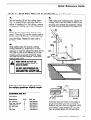
indoor
2.
Hard Mount
w/Adjm Bracket,
continued
7.
Place “Z” supports [a] on the ceiling’s top
surface. For tile ceilings, make sure the
edge of the supports rests flush with edges
of tile. Refer to diagram on page Q-4.
Bring the three mounting tabs of the
housing down and tighten their screws to
secure. Then secure the plate to the I”
supports using washers and wing nuts [h].
3.
8.
Place the two “L” supports [b]-cut to
length, if necessary-over
the threaded
studs of the “Z” supports and fasten
together using four washers and wing nuts
provided [cl.
4.
From inside the housing, insert the four
screws [d] provided through the holes in
the top of the housing and into the
adapter plate [e].
Using an S-hook, hang safety chain [i]
from a strong ceiling member and, using a
second S-hook, connect the other end of
the chain to one of the ‘I-” supports. Keep
the chain taut. Tighten both ends of each
S-hook.
A
DO NOT USE SPRINKLER
FIRE CONTROL
SYSTEM
SECURING
THE SAFETY
5.
Place enough spacers [f] over each stud
in the adapter plate to compensate for
the thickness of the ceiling.
6.
With its three mounting tabs [g] in the up
position, insert the housing into the
ceiling hole until the studs in the plate fit
through the slots in the “L” supports.
KEEP CHAIN AS TAUT AS
POSSIBLE! CLOSE ENDS OF
EACH S-HOOK!
OR
FOR
CHAIN!
9.
Feed video and multiconductor cables [j]
through one of the two holes in the side
of the housing. Then cover all openings
in the housing with the aluminum tape
supplied. The housing is now ready for
chassis installation (page Q-8).
SENSORVISION
SpeedDome
Q-3
Indoor
2x2
2x2 Install
Components
RHl2X2 is an ordering
contains the following
0400-0496-01 - 2x2
0351-0376-01 - 2x2
We
Qty.
Bar, ceiling tee
S-hook, open
Chain, Navy link
Tab
Clip, T-bar
Part
1
2
6 FT
2
4
- RH/2X2
- 0200-0176-01
vehicle for 0200-0176-01,
items:
SpeedDome Housing
Housing Install Kit:
Description
Mount
which
No.
0500-0263-01
2897-0004
2898-0002
0500-0264-04
1400-0033-01
Procedure
1.
Remove the ceiling tile(s) and inspect
the ceiling frame. The frame must be
capable of withstanding 9kg (20 Ibs)* of
weight and the forces generated as the
dome pans and tilts.
A
IF CEILING
FRAME CANNOT
SUPPORT DOME, ASK BUILDING
MAINTENANCE
TO INSTALL
ADDITIONAL
CEILING
SUPPORTS.
For 2x2 openings,
skip
steps
2 and 3.
2.
AREA
Cut the 2x4 ceiling tile to 60.3cm (23.75”)
using the length of the T-bar supplied [a]
as a guide. Then, attach this T-bar (see
detail) by centering steel tab [b] through
the slot at end of the T-bar. Bend the tab
as shown [cl.
3.
Slide the tab through the slot in the
existing frame [d] 61cm (24”) from the
T-bar opposite. Bend the ends of the tab
outward [e] to secure. Repeat for the other
end of bar.
*U.S. Customary
Q-4
61 cm (24”)
Measurements
SENSORVISION
in italics are rounded
SpeedDome
off.
OF DETAIL
indoor
2x2
Tile Mount
Installation,
continued
4.
7.
Set the housing [f] into the ceiling opening. For slightly larger openings, see box
below. If installing in a 2x2 ceiling, remove
an adjacent ceiling tile to aid installation.
Feed video and multiconductor cables [m]
through one of the two holes in side of the
housing and reinstall the adjacent ceiling
tile. See chassis installation on page Q-8.
5.
Clamp the housing to the T-bars by snapping a T-bar clip [g] over the raised edge of
the housing and the T-bar. Center this clip
along the edge. Repeat for each side of
housing.
6.
Wrap safety chain [h] around a strong
ceiling member [i]; attaching it to itself
using an S- hook [j]. Attach the other end of
the chain to one of two eyelets [k] on the
housing using a second S-hook [I]. Keep
the chain as taut as oossible. Close both
ends of each hook. ’
KEEP CHAIN AS TAUT AS
POSSIBLE!
CLOSE ENDS OF
EACH S-HOOK!
DO NOT USE SPRINKLER
FIRE CONTROL
SYSTEM
SECURING
THE SAFETY
OR
FOR
CHAIN!
Add extension
bars to the housing
for ceiling
openings
slightly
larger
than 2x2 or 2x4.
Extension
Bar Kit
0351-0243-01
Description
Bar, extension
Rivet, pop .125x.390
Washer, flat No. 5
Bar, ceiling tee
Tab
Clip, T-bar
c2ty.
4
16
16
1
2
4
Part
top view
No.
0500-3326-01
2673-0004-05
2848-i 408-01
0500-0648-01
0500-0264-04
1400-0033-01
Extension bars [A] mount to the edge of
the housing [B] to provide a proper fit.
Buttjoint as many bars as required using
pop rivets [C] and washers [D], four per
bar, as shown above. Do not use clips.
SENSORVISION
SpeedDome
Q-5
Indoor
Pendant
Method
1 - Standard
Required
Parts
Pendent
Components:
Mount
Mount
- RHlPM
InstaIlation
f
6.1M
(203 MAX
RHIPM is an ordering vehicle for dlRHIPM,
which contains the following assemblies:
0351-0391-01 - Adjustable I-Beam Clamp Kit (not used with this method)
0200-0177-01
- Pendant Housing Assembly; also includes:
0351-0392-01
- Pendant Install Kit, which contains the following items:
Description
caty.
Part No.
Flange, 1 -l/4” dia.
1
1400-0069-01
Fitting, pipe tee
1
1417-0040-01
Nipple, short l-l/4
1
1417-0041-01
Anchor bolt, 1/4x2-1/4
w/hardware
4
2680-0011
Pipe, l-l/4’, straight, 6m
max, threaded both ends
1
CE supplied
1
0500-3964-01
Cap
Procedure
1.
3.
Using the flange [a] as a template, mark
hole locations on ceiling for four bolts.
Remove the flange and drill four .64cm
(l/4”)* holes to required depth.
For each hole, screw two nuts onto the
anchor bolt provided, with two threads of the
second nut extend- ing over end of the bolt
to protect the bolt threads from damage [b].
Hammer the bolt into ceiling leaving only
its threads exposed. Remove the nuts and
bolt the flange to the ceiling using the flat
washers, lock wazhers and nuts supplied [cl.
.......
QB f
la~~
[c]$
kl I31 B
[fl[p
-Y
[iI
9
Thread the straight pipe [d] (not supplied)
and nipple [e] into pipe tee [f]. Thread the
nipple of the entire assembly into flange [g].
Q-6
Slip the cap [i] onto the pipe, then thread
housing [j] onto the pipe. See chassis
installation on page Q-8.
Customary
Measurements
SENSORVISION
in italics are rounded
SpeedDome
Ih1
dl
2.
*U.S.
Feed video and multiconductor cables [h]
through center hole of pipe tee and down
through the pipe. Note: Remove the CinchJones connector, if used, to enter pipe.
off.
m
/n&or
pendant
Method
Mount
2 - I-Beam
Required
m
Rn/pM
. .._.............._.~........~.~.~.~..............~.~.~....~.~.
-.-
Installation
Parts
RHIPM is an ordering vehicle for OlRHIPM, which, contains the following
0400-0505-01
- Pendant Housing Assembly; also includes:
0351-0392-01 - Pendant Install Kit (not used with this method)
0351-0391-01 - Adjustable I-Beam Clamp Kit:
Description
Base plate
Clamp plate
Screw, math. M6x70
Washer, flat
Nut, locking
Fitting, pipe nipple
Fitting, pipe tee
Flange, l-114”
Qty.
1
2
4
12
8
1
1
1
components:
Part No.
0500-3975-01
0500-3976-01
5801-4194-311
5840-0500-020
5826-0500-020
1417-0041-01
1417-0040-01
1400-0069-01
Procedure
l-beam attachment.
Set the base plate
[a] against a suitable ceiling member [b].
Secure the plate using clamps [c] and
hardware supplied [d]-see base plate
hole-to-hole dimensions, below. Attach the
flange [e] using hardware supplied [f].
Vertical/Horizontal
mounting.
Thread
nipples [g] and [h] into the pipe tee [i], and
screw the entire assembly into the base [j].
Next, feed video and multiconductor cables
[k] through center hole of pipe tee. Note:
Remove the Cinch-Jones connector, if used,
to enter pipe.
Finally, thread the housing [I] onto the pipe.
See chassis installation on page Q-8.
til
i&i
Horizontal
Mounting
km
Base plate
hole-to-hole
dimensions:
Note: If replacing pipe tee
with pipe, cable exiting pipe tee
must be no farther than 15.2cm
(6”) from l-beam clamp.
4
l U .S. Customary
’
I4 128mm
179mm
230mm
Measurements
(53’
(77
(91
’
’
in italics are I*ounded
off.
SENSORVISION
SpeedDome
Q-7
SpeedDome
Required
Chassis
Installation
Parts
Skirt Assembly - 0400-0507-01
SpeedDome Install Kit - 0351-0377-01:
Description
Connector, BNC
BNC jack
Nylon Cable Tie
Ctty.
1
1
1
Part
No.
211 l-0035-01
211 l-0034-01
6009-0006
Procedure
1.
Snap the ball [a] of the lanyard
hanging from the chassis into the
bracket [b] at the top of the housing.
2.
Squeeze the spring-loaded ejector
pins [c] together to seat the chassis in
the corner receptacles [d]. The PC
board must face the cables exiting
the access holes in the housing.
r-
3.
With the chassis hanging down,
connect the video and multiconductor
cables to their receptacles [e]-refer
to instructions on page Q-19. Do not
use the alarm input connector [f]
unless connecting alarms to domes.
4.
Set the thumbwheel switches [g] to the
appropriate address. Example for address 16:
Thumbwheel
MSB
Alarm
Input
Q-S
SENSORVISION
Switches
LSB
I
Video
SpeedDome
AC
and
Data
(continued on page Q-9)
Chassis
5.
Installation,
continued
Attach the skirt assembly or optional
bubble assembly [h] to the chassis by
inserting its T-lanyard into a slot [i] on the
chassis until both ends catch securely.
6.
To lock the chassis in the housing,
squeeze ejector pins [j] and swing the
chassis all the way up, while easing the
cables up through the access holes.
Release these pins into the remaining
corner receptacles.
5
a.
To compensate
for accidental jarring
during assembly, recalibrate the dome
as follows:
a. At the console, call up the
dome address number.
b. Press and hold the FAST key.
Then-in order-press and
hold the ZOOM OUT,
FOCUS FAR, and IRIS OPEN
keys.
When the dome begins to pan
and tilt, release the keys.
Once calibrated, which takes about
a minute, the dome is ready for use.
Installation is complete.
7.
Snap the four pins of the skirt (or bubble)
assembly into the four chassis
receptacles [k].
SENSORVISION
SpeedDome
Q-9
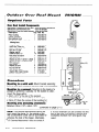
Outdoor
Over
l?oof
Mount
- RHORM
Required
Parts
.._.__
---_._....______.I._._..~..~~.~.~....~.....~.~.~.~.~.~.......................~.~.~.~.~.~.~...~.~
-_._._._...._...._.._..............
Over
Roof
Install
Components
0200-0179-01,
SpeedDome Housing Assv - ships with Outdoor SpeedDome
0200-0173-01, Over-Roof Mount Ati
- - ships with RHORM ’
0200-0174-01,
Over-Roof Install Hardware - ships with RHORM:
Description
Qty. Part No.
Plate, mounting
1
0500-3637-01
Bracket, mounting
1
0500-3638-01
Base wall/pole mount
1
0500-3463-01
Over-Roof Install Kit - contains the
1
0351-0279-01
following items:
Fitting, 90” pipe
Anchor bolt, 1/2x5 l/2”
Anchor, hollow wall, w/ P
Bolt, hex 1/2-13x4”
Washer, lockl/2”
Cable tie, Nylon, 7.5”
Rod, thread 1/2-l 3x16”
Nut, Hex l/2-13
Washer, flat, SS, P, .531 ID X 1.250D
Washer, fiat, ST, Z, .812lD X 2.00D
RTV compound
Pipe sealant
Washer, flat 5/l 6”
Nut, hex 5116-l 8”
Bolt, hex 3/6-l 6x314”
Adaptor, BNC, male to female
Nut, hex, 1.5” pipe w/seal
1
4
3
1
4
10
1
2
2
1
1
1
8
8
2
1
1
0500-3499-01
2860-0049
2860-0074-01
2860-8917-01
2847-0300
6009-0005
0500-2734-01
2838-9117-04
2848-8101-l 1
2848-l 409-l 6
1600-0001
1600-0095-01
2848-6301-02
2838-9116-01
2880-0082-01
2113-0004
1417-0042-01
r
25cm
(101
1
Procedure
Mounting
to a solid wall: Mount bracket assembly
[a] to a solid wall or poured concrete cap, where possible.
Mounting
to a parapet:
Mounting to the inside of a
parapet is preferred. Typically, for the bubble to clear,
mount the base within:
l 25cm (ION)* of the top of the parapet.
A parapet with a 5cm (2”) lip is shown [b].
l 13cm (5”) from the corner of the building
[cl.
Mounting
area (including
clearance):
Minimum 33cm (73”) x 48cm (19”). ,
,.
,
a ..
(continuea on page u-l 1)
Note: If the above requirements cannot be
met, mount the dome to the outside of the
wall (a decorative cover can be purchased to
enhance the look of the base). Alternately,
* U.S. Customary
Q-10
Measurements
SENSORVISION
in italics are rounded
SpeedDome
off.
(top \
a lo-inch extender can be screwed into the
end of the pipe, but tell the customer that
increased vibration from wind gusts may
result.
Outdoor
Over Roof Mount,
continued
II-m-l
II
Place plate [a] in desired loca- tion,
level, and mark slots. Plate MUST BE
LEVEL. Remove tern- plate, then drill
four l/2-inch holes to the required
depth for type of wall and hardware
used.
-
rl
II
TOP4
II
-
-
[cl WI [el
0
For each hole into solid concrete, screw two nuts
[b] onto an anchor bolt, with two threads of second
nut extending over end of bolt to protect threads.
Hammer bolt into wall leaving l-1/4 inch exposed.
Remove nuts and attach a l/2-inch flat washer [cl,
lock washer [d] and nut [e]. If voids are
encountered, see NOTE below.
Lil-
Slip slots of mounting plate [f] over bolts,
togglers, or rods [g] and secure using proper
hardware. Mount base [h] to the plate using
hardware provided-any
set of four studs can be
used. Feed cables through bottom of bracket [il.
Slip smooth-end of pipe [j] over cable and into
bracket. Secure pipe by tightening screw [k] and
level by adjusting nuts [I]. If using a decorative
cover [m], slide it over pipe.
1
[ml
rover
optional)
Voids
encountered
while
One void
only: Insert toggler (provided) through
hole where void ocurred. Insert associated bolt.
A.
INSERT
metal
c.
I
I
SLIDE
plastic
I
I
‘p\l
go- =
[kl-
Apply pipe sealant to pipe threads [n], then slip
elbow [o] over cable and screw elbow onto pipe.
Once on, elbow opening should face down.
Note: Approximately 36cm (14”) of cable must
exit elbow. The mount is now ready for housing
and chassis installation on page Q-16.
NOTE:
en- ,=
PI-
-1
[al
drilling...
TWO Or more
voids: For each void, drill hole
through wall. Then, insert threaded rod (provided)
through hole and attach hardware shown. Purchase
additional rods/hardware as required.
MOUNTlNG
BRACKET
GOES HERE
II2 inch
Flat Washer
B.
D.
PULL
plastic
I
I
SNAP
plastic
,
off
\
chant
nel.
pushing
outward.
iiL/
I
I
It2 inch
Flat Washer
I
I
SENSORVISION
Nut
3/4 inch
Flat Washer
SpeedDome
Q-11
Outdoor
Wall Mount - RHOWM
Corner Bracket
Option - RW770
Required
0200-0179-01
SpeedDome,
Wall
Parts
- Outdoor SpeedDome Housing Assembly,
is required for these installation options.
Mount
Option
(RHOWM)
RHOWM is the orderfna vehicle for 0200-0162-01
which contains the following items:
Description
Base, wall/pole
Support, wall/pole
Pipe, 12 in. long
Fitting, 90” pipe
Wall Mount Install Kit contains the
following items:
Washer, flat ST, Z, 344lDX.6750D
Nut, hex Nylon-LK CAD 5/16-l 8
Anchor, wedge, bolt, l/4 X 2.2
Pipe sealant
Plug, l-7/8 x 1
RTV compound
Adaptor, BNC, male to female
Nut, hex, 1.5” pipe with seal
q
Corner
Mount
which ships with Outdoor
Option
- Outdoor Wall Mount w/Hardware,
Qty.
1
1
1
1
1
Part No.
0500-3463-01
0500-3464-01
0500-3465-01
0500-3499-01
03518283-01
4
4
4
1
1
1
1
1
2848-6301-02
2838-9116-01
2880-0011
1600-0095-01
0649-0685-01
1600-0001
2113-0004
1417-0042-01
-top view-
l
a
[al
(RH170)
RH170 is the ordering vehicle for 0200-0175-01
which provides the following item:
1
Corner mounting bracket
OPTlONAL
CORNER
BRACKET
I0
OIb;
“,
- Corner Bracket Mount,
0
0500-3636-01
Procedure
D
[cl- i G--i
.
w
l-l
(front view)
0
0
(front view)
Place wall-mount base [a] or corner bracket [b] in
desired location, level, and mark mounting holes [cl.
Drill four 6.5cm (l/4”) holes to the required depth.
For each hole:
l
Screw two nuts onto end of anchor bolt, with two
threads of second nut extending over end of
bolt to protect threads [d]. Lock the nuts in
position by tightening them against each other.
l
Hammer bolt into wall leaving 3.2cm (1 -l/4”) of
bolt exposed. Then, loosen and remove nuts.
Slip base shown or corner bracket over bolts and
secure using hardware [e]. Secure base to studs of
corner bracket, if used. Then loosely thread a
washer and nut [f] onto the four threaded studs of
the base [g].
(continued on page Q-13)
Q-12
SENSORVISION
SpeedDOme
side view)
(top view) I
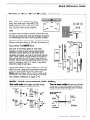
Outdoor
Wall Mount
and Corner
Bracket
Feed camera dome cables [h] through
mounting bracket (i).
Apply sealant [j] to threads of straight
pipe [k], then slip pipe over cable and
screw pipe into bracket.
Slip elbow [I] over cable and screw elbow
onto pipe. Once on, elbow opening should
face down. Note: Approximately 36cm (74”)*
of cable must exit elbow. If so, insert plug [m]
and seal with RTV.
3fkm (14
_I
Hook bracket [n] on threaded stud between
washer and base [o] while feeding excess
cable [p] back through hole in bracket. Level,
and tighten nuts [q] on both sides of base to
secure.
0
The mount is now ready for housing and
chassis installation. See page Q-16.
0
0
0
II
*U.S.
Customary
Measurements
in italics are rounded
off.
continued
~~
SENSORVISION
bl
[PI II
SpeedDome
Q-13
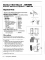
Outdoor
Pole
Required
0200-0179-01
SpeedDome,
Pole
Mount
m RHOPM
Parts
- Outdoor SpeedDome Housing Assembly, which ships with Outdoor
is required for these installation options.
Mount
Components
(RHOPM):
RHOPM is the ordering vehicle for 0200-0161-01,
Outdoor Pole Mount w/Hardware,
which contains the following items:
Description
Qty. Part No.
Note: Two clamp packages are
1
0500-3463-01
Base, Wall/Pole
provided: one for the dome, one for
Support, Wall/Pole
1
0500-3464-01
the
J-box. Straps in each package
1
0500-3465-01
Pipe, 12 in. Long
are
sufficient for 1Ocm (4’7 to
2
6010-0043-01
Clamp package (see note)
30.5cm
(72”) wide poles. For larger
1
0500-3499-01
Pitting, 90” pipe
widths, order an additional package
Pole Mount Install Kit contains the
1
0351-0282-01
following items:
Washer, flat 5/l 6
4
2848-6301-02
Nut, hex 5/l 6-l 8
4
2838-9116-01
Loosely thread washer and nut [i] onto the
Screw, M, HXHD, SS, l/4 - 20 X 1” 2
2802-8401-72
four
threaded studs of base [j]. Next, insert
RTV compound
1
1600-0001
two
l/4-20
leveling screws [k] into bracket
Pipe sealant
1
1600-0095-01
[I].
Then,
hook
bracket on threaded stud
Plug, l-7/8 dia. 1” thick
1
0649-0685-01
Adaptor, BNC, jack to plug
1
2113-0004
between washer and base while feeding
Nut, hex 1.5” pipe w/seal
1
1417-0042-01
excess cable [m] back through hole in base.
Procedure
Feed camera dome cables [a] through the
large hole in mounting base [b].
Following the directions on back of the
clamp package (see NOTE above), strap
the mounting base securely to the pole [cl.
Feed cables exiting base through the hole
in the mounting bracket [d].
Apply sealant [e] to threads of straight pipe [f],
then slip pipe over cable and screw into
bracket.
Slip elbow [g] over cable and screw elbow
onto pipe. Once on, elbow opening should
face down. Note: Approximately 36cm (74”)”
of cable must exit elbow. If so, insert plug [h]
into bracket and seal with RTV.
*U.S. Customary
Q-14
Measurements
SENSORVISION
in italics are rounded
SpeedDome
off.
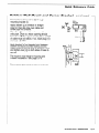
Use leveling screws to level. Tighten nuts
on both sides of base to secure. The mount
is now ready for housing and chassis
installation. See page Q-16.
Outdoor
Ceiling
Required
0200-0179-01
SpeedDome,
Ceiling
Mount
- RUOCM
Parts
- Outdoor SpeedDome Housing Assembly,
is required for these installation options.
Mount
Components
which ships with Outdoor
(RHOCM)
RHOCM is an ordering vehicle for 0200-0163-01 which contains the following items:
Description
Qty.
1
Flange
1
Fitting, pipe tee
Nipple, short l-l/2x 2
2
Anchor bolt, 114x2-114, w/hardware
4
1
Pipe sealant
1
Plug, l-7/8 dia., 1” thick
1
RTV compound
1
Label, blank, paper, thermal
1
Adaptor, BNC, male to female
Nut, hex, 1.5” pipe w/seal
1
Outdoor Ceiling Mount w/Hardware,
Part No.
1400-0056-01
1417-0036-01
1417-0037-01
2880-0011
1600-0095-01
0649-0685-01
1600-0001
2450-0008-01
2113-0004
1417-0042-01
Procedure
Place the mounting flange [a] on the
ceiling in the desired location. Then, using
the flange as a template, mark locations for
four bolt holes. Remove the flange.
The mount is now ready for housing and
chassis installation. See page Q-16.
Drill four l/4-inch holes to the required
depth. For each hole, screw two nuts
onto an anchor bolt, with two threads of
second nut extending over end of bolt to
protect threads [b].
Hammer the bolt into the ceiling leaving
I-114 inch of bolt exposed. Remove nuts.
Bolt the mounting flange to the ceiling
using a l/2-inch flat washer [cl, lock
washer [d], and nut [e].
Apply pipe sealant to nipples [f], then
screw nipples into the pipe tee [g].
Screw the entire assembly into the flange
[h]. Then, feed the camera dome sables [i]
through the center hole of the pipe tee.
Note: Approximately 36cm (74”) of cable
must exit the nipple. If so, insert plug [j]
and seal with RTV.
*U.S.
Customary
Measurements
in italics are rounded
[hl
off.
SENSORVISION
SpeedDome
Q-15
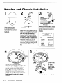
Housing
and
Chassis
2
Installation
Id
FEMALE
CONNECTOR
from J-Box
Using tamper-proof tool
(T-20) remove captive
bubble attachment screws [a]
from housing, then remove
bubble [b].
[h
Screw 1.5” hex nut [cl, with its white (or
yellow) seal facing the cap [d], onto the
pipe. Next, apply pipe sealant [e] to
threads of elbow (or nipple, if this is a
ceiling mount). Then feed the composite cable (f) through the SpeedDome
cap [d] and through the housing [g].
Thread the dome housing onto the
elbow (or nipple), compressing the cap
against the housing until tight. Level as
shown [h]. Apply RTV around the hex
nut.
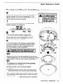
Referring to the chart below, replace
the Cinch-Jones connector [i] with
female compression connector b]
(located at P4 on the SpeedDome
chassis).
Female Compression-Type
Connector
PIN CONNECTIONS
PIN
1
2
3
4
5
6
7
DESCRIPTION
data out (Lo)
data out (Hi)
brown
yellow
black
red
white
green
orange
gd.
%a in (Lo)
data in (Hi)
7
Next, connect the composite cable
compression connector [k] to J2, and the video
connector to Jl , on the Outdoor Interface
Board [I], mounted on the outside of the
bracket. Make sure when connecting to this
board, that the screws of the compression
connector are turned toward the inner black
assembly. Tie wrap the composite cable to the
bracket assembly to make way for chassis
installation.
Q-16
SENSORVISION
SpeedDome
iI.
\
ti
Snap the ball of
the lanyard [m]
in- to the
bracket [n] at
the top of the
housing.
L’
(continued on page Q-17)
Housing
and
Chassis
Installation,
6
Squeeze the spring-loaded ejector pins [n] together to
seat the chassis in the corner receptacles [o]. The
RS422 board [p] must face the SpeedDome interface
board cables [q] inside the housing.
7
continued
/
To connect
alarm to
an outdoor SpeedDome, add lightning
protection
using a
dataline
protector,
PN 4815-0021-01.
Set the thumbwheel switches [r] to the appropriate
address. Example: for address 16,
Alarm
Input
I
Video
AC and
Data
8
Then, with the camera chassis hanging down,
connect the video and data SpeedDome Interface
Board cables [q] to their receptacles [s]. Do not
use the alarm input connector [t].
9
To lock the chassis in the housing, squeeze ejector
pins [u] and swing the chassis all the way up, while
easing the cables into place. Release these pins
into the remaining corner receptacles.
IAl
ENSURE EJECTOR PINS ARE FULLY
INSERTED
IN THE RECEPTACLES.
I
10
Snap the four pins of the skirt assembly [v] into the four
chassis receptacles [w]. Then screw the attachment screws 1
i
of the bubble [x] into the three housing receptacles [y].
11
To compensate for accidental jarring during assembly,
recalibrate the dome as follows:
a. At the console, call up the dome address
number.
b. Press and hold the fast key. Then-in order-press
and hold the zoom out, focus far, and iris open keys.
When the dome begins to pan and tilt, release the keys.
Once calibrated, which takes about a minute, the dome
is ready for use.
DOME INSTALLATION
IS COMPLETE.
SENSORVISION
SpeedDome
Q-17
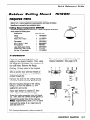
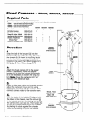
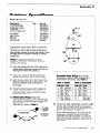
Fixed
Cameras
Required
-
RD~~~,RD~OOA,
~~50043
Parts
There are
RD500
RD500A
RDSOOB
three indoor mounting options to place fixed cameras in SpeedDome bubbles:
- uses an Indoor 2x2 Indoor Housing
- uses an Indoor Pendant Housina
- uses an Indoor Hard Mount
RD500
RD500A
RDLOOB
Description
Part No.
caty.
Qty.
Qty.
2x2 Indoor Housing
Pendant Indoor Housing
Clamp Kit, Adjust. I-Beam
Hard Mount Indoor Housing
Chassis, Fixed/Drone
Shroud, Fixed l
Bubble Kit, Smoked, g-Inch
0200-0176-01
0200-0177-01
0351-0391-01
0200-0176-01
0400-0529-01
0500-4216-01
0351-0366-03
1
1
1
1
1
1
1
1
1
1
1
1
1
I
,
Procedure
1.
Chassis
Assembly
#4QQ-0529-01
0
I
I
I
I
I
I
-
Snap the ball of the lanyard [a] into the
bracket at the top of the housing. Then flex
the chassis [b] to insert its mounting studs
into the four corner mounts of the dome
housing to be used: Hard Mount (page Q-l),
2x2 (page Q-4), or I-Beam (page Q-7).
I
I
I
I
I
-
-
I
I
I
2.
Attach the fixed camera [c] to the swivel
mount. If necessary, move the adapter
bracket [d] to turn the camera horizontally
(it is not necessary to loosen the wing nut
[e]). Note: Cover the camera’s LED “on”
indicator with electrical tape.
i ;
I 1
I
Fixed
Camera
I
-
t
.’
I
I
I
I
\
f’LED
4 Indicai
-fsib
I
3.
I
Using a video test cable and portable monitor,
adjust the camera’s focus and iris using
information provided with the camera. Then,
connect camera video to the console room.
Shroud,
Q- 18
SENSORVISION
SpeedDomf?
(shlps with
04QQ-0529-01)
I
I
I
I
I
I
I
I
I
I
I
I
I
Fixed
0500~4218-m
4.
With the studs of the bubble [f] aligned with
the holes in the chassis, nest the shroud [g]
in the bubble and turn its viewing slot so that
the camera lens can see out. Then fasten the
shroud and bubble assembly to the chassis
by placing its studs against the chassis
holes and pressing firmly on the bubble.
i
[cl
I
w
+
I
I
I e
I
181
I
;
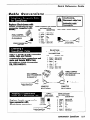
Cable
Conversions
Replace Cinch-Jones
with
female compression-type
connector
(supplied
with
dome).
FEMALE COMPRESSION-TYF’ECONNECT
PN 2109-0254-06
1
Ed
Female Compression-Type
Connector
PIN CONNECTIONS
PIN
DESCRIPTION
1
2
3
4
5
6
brown
yellow
black
red
white
green
7
Orange
. ..oc add Patch
data out (Lo)
data out (Hi)
ac
iI.
:zf
*E&f
PN 6650-9657-61
from J-Box
Male and Female
Compression-Type
Connectors
PIN COf JECTIONS
Add to a length of bulk composite
cable, male and female
compression-type
connectors
and
male and female BNCs from
SpeedDome
Cable Conversion
Kit, 0351-0403-01.
MALE COMPRESSION-TYPECONNECTOR
PN 2109-6271-07
PIN
1
2
3
4
5
6
7
DESCRIPTION
brown
yellow
black
red
white
green
orange
data out (Lo)
data out (Hi)
Ed.
ac
data in (Lo)
data in (Hi)
FEMALE COMPRESSION-TYPECONNECTOR
’ PN 2199-0254-06
’
.-f
Existing SpeedDome c
cable from J-Box
Cable.
b
-L==
FEMALE BNC
CONNECTOR
PN 211 l-0034-01
To SpeedDome
MALE BNC
CONNECTOR
PN 2111-0033-01
DESCRIPTION
Replace
female
compressiontype connector
with
Cinch-Jones
connector.
1
2
3
4
5
6
7
8
orange
green
black
red
white
drain
brown
yellow
data
data
ac
Gnd.
ac
N.C.
data
data
SENSORVISION
out (Hi)
out (Lo)
in (Lo)
in (Hi)
SpeedDOme
Q-19
SENSORVISION SpeedDome
A-l
A-2
SENSORVISION SpeedDome
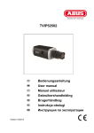
Appendix A
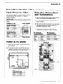
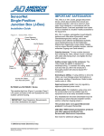
Overview
This appendix describes the interconnection and switch settings
required to operate a Sensormatic Indoor SpeedDome camera
device from an American Dynamics 2083-02A Code Translator.
The 2083-02A is part of an American Dynamics switching system that also consists of a CPU and matrix switching devices.
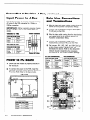
Figure 1 illustrates a typical system.
Note:
This appendix
presents information
useful for the
installation and troubleshooting
of these devices; however, it
does not discuss all aspects of their installation or calibration.
Refer to the Installation and Service sections of this manual and
the appropriate
American Dynamics installation and service
manuals for this information.
Figure
1. Block
diagram
of typical
system
p!iyEq
(Swatch Bays, Alarm interfaces, Etc.)
SENSORMATIC
SpeedDome
I
SENSORVISION SpeedDome
A-3
American
208342A
Translator
Dvnamics
&de
The American Dynamics 2083-02A Code Translator enables
American Dynamics switching equipment to operate Sensormatic SpeedDomes
and Mini Domes. The code translator provides two types of inputs and three types of outputs.
Note:
Up to 16 cameras may be connected directly to a Code
Translator
assuming
external
power considerations
are
provided. The J-Box is optional.
Inputs
1.
Control (Manchester) Code-Using
the terminals marked
W, and S on the translator’s control code connector, up
64 domes can be controlled
by a 1650 switcher, or
domes by a 2150 switcher. Additional
domes can
controlled through multiple 2083-02A units.
13,
to
32
be
2.
High Speed Data Line-The
Data Line BNC connectors are
marked
input and output on the rear panel. The input
connector receives control codes from a 1995 or 1996 CPU;
the output connector
is a loop-through
connection
that
feeds other translators (or other devices).
Note:
If the 2083-02A is the last device in line, the output
connector must be terminated with a 75 ohm resistor. Using
the Data Line connections, a single translator can control up
to four groups of 99 cameras from a possible 1024 using a
1996 CPU, or 512 using a 1995 CPU.
outputs
1.
RS-422 Bidirectional
Communications-to
dome (or optionally through a J-Box).
2
RS-232 communications-for
connection back to the CPU.
When used, alarm contact closures on the dome will
emulate an Alarm Interface unit.
3.
A Normally Open (NO) or Normally Closed (NC) contact
closure -from an internal alarm relay, triggered whenever a
contact closure is made in a controlled dome.
Items 1 and 2 are discussed
sections.
A-4
SENSORVISION SpeedDome
in greater
a Sensormatic
detail in the following
Appendix A
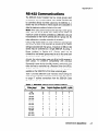
RS-422
Communications
The 2083-02A Code Translator has four output groups, each
consisting of four individual outputs. Up to sixteen cameras may
be controlled directly via these outputs by the 2083-02, or JBoxes may be connected
to these outputs and cascaded
to
allow the maximum number of outputs to be used.
Note: When using Control Code as the data input, each group
used must be set as group one. Using control code, the
maximum number of domes controlled by a 2083-02A is 64, and
the addresses for the first 64 cameras are all in group one. No
other addressing or number conversion is necessary.
Using a High Speed Data Line, each of the four output groups
can control a block of 99 cameras, as defined by DIP switch
settings associated with that group. A maximum of 396 (4 X 99)
domes may be controlled by a single 2083-02A by using JBoxes (outlined
in Section
4.0). Groups
need not be
consecutive, and several groups may be set to the same bank
of cameras to better utilize rear panel connections if necessary.
Actually, the code translator uses only 98 of the 99 cameras in
each group.
To preserve
compatibility
with previous
Sensormatic dome devices, the 64th camera in each block must
either be fixed or controlled via a Receiver Driver Unit (RDU).
Another alternative is to use the pseudo numbering
system
available on the 1996 CPU to fill in those numerical gaps.
Table 1 provides 2083-02A Code Translator switch settings for
each group to select the appropriate camera bank. The drawing
on page 17 outlines connections
from the 2083-02A
Code
Translator to other devices.
Table
1. 2083-02A
output
group
switch
settings
Video Input
Camera Numbers
Data
Bank
Switch
A
Positions
B
l-99
loo-198
A
0
0
0
0
0
0
0
0
1
1
0
0
1
1
0
1
0
1
1
1
0
1
1
1
0
1
0
0
0
0
0
0
1
1
0
199-297
B
C
298-396
397495
D
E
496-594
595-693
694-792
F
G
H
793-891
892-990
991-1024
I
0
0
1
J
K
1
1
0
0
0
0
(O=OFF, 1 =ON)
C
D
SENSORVISION SpeedDome
A-5
RS-232
Communications
Two FE-232 ports are provided on the rear panel, labeled input
and output. The output port is for connection to the switcher
control system or the input port of another 2083-02A or 2096
Alarm Interface unit. The input port accepts signals from other
devices for cascading several units.
The RS-232 connectors
are 8-pin modular
connectors. Pin designations for those connectors
the Table 2 below.
Table
I
2. RS-232
connector
RJ-45 type
are shown in
pinouts
Pin
Input
output
2
4
5
7
Shield
RCD
XMIT
GROUND
Shield
RCD
XMIT
GROUND
Remaining Pins-No Connection
For the use and addressing of alarm inputs from SpeedDome
devices, consult the Installation manual for the 2083-02A Code
Translator. The installer is also advised to verify that the 208302A being used is set up for SpeedDome rather than Minidome
operation where appropriate.
While the 2083-02A manual states that the baud rate for RS-232
communications
may be set independently
from the SpeedDome baud rate (which must be set at 4800 baud), field
experience indicates that this is not the case. To avoid problems
(symptom would be the 2083-02A not outputting a data stream
on any of the RS-422 lines) it is recommended
that the
baud
rate for all ports
on S5 as indicated
be set to 4800
baud
internally
on Table 4 (this is the factory default):
Please note that with these settings the RS-232 port on the CPU
must also be set to correspond with the interface, as do any
other Alarm Interface units sharing that port (cascaded through
or fed from a 2083-02A unit).
A-6
SENSORVISION
SpedflOfr?e
Appendix
A
Sensormatic
RJ860 J-Box
The Sensormatic
RJ-860 J-Box serves either one
functions depending on the design of the installation:
or two
1.
Provides low voltage (24Vac) power for up to ten domes
when a central power distribution system is not used.
2.
Acts as a RS-422 1 x 10 bidirectional distribution amplifier,
to increase the available number of camera data ports.
Units may be cascaded as needed.
The J-Box has two types of connections: a single spring-loaded
terminal block for connection to a 2083-02A Code Translator,
and ten 8-pin Cinch-Jones plugs for output to camera devices.
The pinouts and interconnections
for these connectors
are
shown on the Camera/J-Box/Switch
Interconnection
Drawing on
page A-l 9.
Note:
All ten Cinch-Jones
Plugs are identical
and
interchangeable.
The system Technical
Specification Manual
will identify a dome by J-Box and Port (connector) numbers for
purposes of identification
and troubleshooting
only. Doing so
has no effect on system functionality.
Many larger CCTV Systems will rely on a central power
distribution system. If that is the case, the 28Vac connection
from the J-Box will not be used, and a separate power line must
be run from the Power Distribution System to the dome.
SENSORVISION
!$X?edDOme
A-7
Sensormatic
RAS585LSlRAS586LS
Series Speed&b
The Sensormatic
SpeedDome
camera device. All connections
its Unicafd interface Board.
is an integrated
pan/tilt/zoom
to the outside world are through
Data connections (to a J-Box or 2083-02A Code Translator) are
designated
on the Camera/J-Box/Switch
Interconnection
Drawing on page A-19. Power connections
are either through
the J-Box or another power source, such as a central power
distribution system.
Certain functions may also be set on a bank of eight DIP
switches designated Sl on the Unicard Interface Board. These
switch settings are indicated in the table below. Note that the
only difference
between
NTSC (USA) and PAL (Foreign)
versions is the setting of Sl switch 2. The dome automatically
adjusts to the power line frequency (50Hz or 60Hz).
Table
3. SpeedDome
Switch
6
7*
7t
8
*
t
Sl DIP switch
off
On
Color
NTSC
Lens Motor On
Auto Iris
Line Lock
Enable
Target fast
Alarms (N.0)
Short Lens
Indoor
B&W
PAL
Lens Motor Off
Manual Iris
Line Lock
Disable
Quiet
Alarms (N.C)
Long Lens
Outdoor
settings
Default
Camera Dependent
Version Dependent
OFF - Lens Motor On
OFF -Auto Iris
OFF - Line Lock Disable
OFF - Target fast
Indoor domes.
Outdoor domes.
Camera
Addressing
Each camera
system. Note:
the same.
must have its own unique address within the
It is essential that no two cameras be addressed
The dome address is set via two thumbwheel
switches on the
RS-422 Interface Board. Since the address can only be a number from 01 to 99, numbers above this range are obtained by
connecting the dome to a higher data bank (see Table 1). Table
4 is a conversion chart, showing dome addresses corresponding to camera numbers and the appropriate data bank.
A-8
SENSORVISION SpeedDome
Appendix A
American
Dynamicsto=Sensormatic
Conversion
Charts
SENSORVISION SpeedDome
A-9
Table
4. SpeedDome
Address
Conversion
Chart
DOW
91
92
93
94
95
97
98
99
loo
101
10:
10:
101
105
A-10
42
43
44
45
46
47
48
1
1-64
i-64
1-64
l-64
1-64
l-64
l-64
.54-l
51
I
1
I-fsd
l-64
53
I
l-84
_
1
1
1
99
1
'
1Oi
1Of
~~~~ 10s
113
114
115
116
117
118
14
15
16
17
18
19
.
loo-'
1t
lO&'
loo-'
loo-'
Appendix A
1
Video
I
I
I
I
44
43
1AF.
, I”“-1 193-256
1- 193256
’ 193-256
193-256
193-256
' 193-256
193-256
193-256
193-256
193-256
, .,,-2.56
1 193-256
193-256
193-256
lP%7Fdi
.“”
1
189
1Q-l
1
I
192
I
1 loo-198
I In-l-lcm
93
1 loo-198
SENSORVISION
SpeedDome
A-11
I=
343
344
“N
E
R47
321-384
349
350
z7
E
295
296
297
3QR
,
“.
,
I
98
I
199-297
44
,L I -Jo‘+
321-384
321-384
321-384
321-384
321-384
321-384
321-364
321-384
321-384
321-384
321-384
1 321-364
321-334
_ - .
298-398
A-12
SENSORVISION
I
S/X?t?d~Omt3
I
- - _
257-320
1
Apw
Video
Input/
Camera
Numbers
449
ydix A
Dome
Address
452
4&.
455
420
24
1 397-495
SENSORVISION Speedfbme
A-13
1
520
521
522
523
524
---
529
A-14
.
26
27
26
29
-_
.
49
49
49
Aa
1
I
34
1 49
I Aa
,
I
4,
, ‘w
I Aa
SENSORVISION SpeedDome
Video
I
I
I
1
Appendix A
704
11
1 694-792
B NOT USED]
641-704
1
SENSORVISION SpeedDome
A-15
I
Video
Input/
Camera
1
-.
a2
I
1 694-792
--.
.--
I
784
I1
03
7m
I
-.
a*
812
813
A-16
1
I
824
1
R?c,
I
20
21
32
-_.
.--
.--
1 793-891
1 79? nnr
1 793-891
I
70"
nn.
SENSORVISION SpeedDome
Video
Awl
Video
input/
Camera
Numbers
961
962
963
964
965
966
967
968
969
970
971
972
973
I
Dome
Addtess
,
IV
71
,1
..
,
1
I
I
72
ii
77
78
79
80
81
62
7(Sx A
--- --892-993
892-990
892-990
892490
Q7A
t
t
--.
985
I
I
I
I
--.
988
SENSORVISION SpeedDome
A-17
Camera/&Box/Switch
Interconnection
Drawing
Jl through JlO (FE422 outputs) are
interchangeable
Male Cinch
1
2
3
4
5
6
7
RJ880
J-Box
Motherboard
(0301-0109-01)
!=m!s=l
, . .
. I, .
I
.
. I
12-pin press-release
Connector
on J-Box
Motherboard
12
11
10
9
8
7
6
5
4
3
2
1
green
Data
Data out LO (T-)
red
black
out
out
out
out
1
1
2
2
Pluc
Data out HI
Data out LO
ac
Ground
ac
.
Ea
in LO
Data in HI
Cinch-Jones
Plug at end
of Composite
Cable
HI (T+)
IShield-
HI
LO
HI
LO
I1 I
Data in HI (R+)
Data
1 Aux
1 Aux
2 Aux
2 Aux
in LO
data in
data in
data in
data in
(R-)
HI
LO
HI
LO
1
12-pin
Connector
to AD 2063-02
AD 2083-02
orange
green
black
red
white
drain
brown
yellow
Jones
Male
white
Aux
Aux
Aux
Aux
out
~I
[X] Code
7-pin Connector
to SoeedDome
Controller
Bd.
Translator
WeNedDome
‘I-pin
RS422lAC
brown
Data
Yellow
black
red
white
Connector
-
A?= m
Power
out
Data out
ac
Ground
LO (T-)
HI (T+)
ac
green
Data in LO (R-)
orange
Data
in HI (R+)
.L
1
I!= 111171r
SpeedDom
- ___
Controll
SENSORVISION
re UniCard
ler Board
SpeedDome
A-18
SENSORVSION SpeedDome
B-l
B-2
SENSORVISION SpeedDome
-._^_---._
SensorNet
Network
Understanding
the SensorNet network is very important for a
successful installation. This understanding
will help you plan
an efficient, reliable, and flexible network that can meet the
facility’s long-term needs. This guide provides basic
guidelines
for selecting a suitable topology and installing the
network devices.
Design
SensorNet supports
daisy
network link can be
best suits the link’s
topologies:
link
A star topology has up to four network branches
that connect to a host which serves as the hub.
l
The distinction between daisy chain and backbone
wiring is mostly physical. Daisy chains use separate
cable segments to connect devices, while
backbones connect all devices to one cable.
After the compression
connectors are attached,
two topologies
become electrically
identical.
However, backbone wiring may have a lower
resistance because the cable is not cut.
Network
Design
Consideratiomh
For proper operation, both ends of each SensorNet link must
be terminated. This prevents signals reaching the end of the
line from being reflected back along the line. All SensorNet
devices and hosts have a termination switch or jumper for this
purpose. When in the ‘terminate” position, a resistor is placed
across the SensorNet cable connections
to suppress reflected
signals.
network
chain, backbone, and star. Each
wired to apply the topology that
unique requirements.
A backbone
topology uses a single continuous
cable, with multiple devices attached directly or
through short stup cables. The host can attach
anywhere along the backbone.
l
The receivers on SensorNet devices will operate satisfactorily
at signal levels between 5v and 0.3~ (differential peak-to-peak,
measured with a scope). For installation planning purposes, an
operating range of 5v to Iv is recommended.
A SensorNet
J-Box can be attached as the signal reaches l-2v, to amplify the
signal back to 5v. This will extend the network’s distance and
allow additional devices to be attached.
three
-1
A daisy chain topology originates at the host and
sequentially
connects multiple devices along a
single path until the last device is attached. A
separate twisted-pair
cable connects each device
to the next.
l
Distances and device counts contained in this guide assume
AWQ 22 un-shielded
twisted-pair
cable.
Shielding
adds capacitance,
causing the SensorNet signal level to
decline more rapidly as devices are attached or cable length
increases. When pre-existing wire makes it necessary to use
shielded twisted pair cable, the maximum distance will be
reduced. For example, Belden 8760 cable will typically support
complete network links (including backbone and branches) of
approximately
750m (2500’).
A SensorNet network consists of one or more network
‘links’.
Each link includes a twisted-pair cable,
a SensorNet
host and l-32 SensorNet devices.
A SensorNet link’s
maximum cable length is lkm (3300’). Devices can attach
anywhere along the cable.
Guidelines
:‘j Daisy
Chain
Link
the
Guidelines
With a daisy chain network, a separate
cable
connects
each device
to the next device
in
the chain. This facilitates quick and easy installation.
The daisy chain is a good solution for a temporary
network or where the host has a few devices located
in the same room or area. Consider using a backbone
or star topology when installing large and permanent
networks.
Think of each SensorNet link as a single twisted-pair cable with
a terminating resistor at each end. A host and up to 32 devices
are then placed along the cable. If the host is placed at one end
of the cable, it must be terminated, and can only support one
cable branch.
If the host is placed in any other position, it is not terminated
and can support 2-4 cable branches. In this configuration,
the
last device attached to each cable branch must be terminated.
A J-Box can serve as a host repeater, to add a SensorNet link
and up to 32 more devices, or to allow SensorNet cable runs
beyond 1 km (3300’). For maximum distance, attach the repeater
J-Box at a point where the signal level has reached 1-2~
(differential peak-to-peak,
measured with a scope). This takes
advantage of the prior host’s driver capabilities
while providing
a strong signal for amplification.
No more than 3 repeaters
should be used in series between any two network devices, as
this can create signal distortion, and cause operational errors.
/I
0
Unterminated
SensorNet
Device.’
1.
Terminate devices at both ends of the daisy chain.
Leave all others unterminated.
2.
Attach up to 32 devices
3.
Limit combined cable length (from host to farthest
device) to lkm (3300’) or less.
on each link.
SENSORVISION
SpeedDome
B-3
r SensorNet
/
Network:
Design
daisy chain hosts are usually terminated and placed at
one end; however, this location is not critical. If the host
attaches elsewhere, the network becomes a 2-branch
star. In this configuration,
both end devices are
:erminated and the host is not terminated.
‘. Backbone
Link
Guidelines
I a backbone network, a single
continuous
cable
onnects
all devices
served by the link. The unbroken
able allows you to install a permanent network that
maintains a high level of reliability even when you must
ttach, disconnect, or move a device.
se the backbone topology for large and permanent
etworks; it is also a good solution when conencting
evices located in the same general area.
. Locate the host anywhere
j ; f Star
Link
continued
Guidelines
A star topology is a good solution when using existing
cable. it also allows easy reconfiguration
as devices are
added or relocated.
1.
Terminate devices
maximum). Leave
2.
Attach up to 32 devices
3.
Limit combined cable length (from host to farthest
device) to 1 km (3300’) or less.
4.
Whenever possible, attach devices backbone style,
following the instructions under Backbone Link
Guidelines.
along the backbone.
Backbone
at the end of each branch
all others unterminated.
Style
Star
on each link.
unterminated
devices, strip 1.2cm (.5’) of
from each conductor at the connection
in the middle of the stripped area, and
the device’s compression
connector.
Daisy
Chain
Style
( Host System [
0
Unterminated
n
Terminated SensorNet Device.’
SensorNet Network Cable
-
SensorNet Device.*
0
Unterminated
n
Terminated SensorNet Device.’
SensorNet Network Cable
-
1-4
SENSORVISION
SpeedDome
SensorNet Device.’
(4
on each link.
1. Limit combined cable length (from host to farthest
device) to 1 km (3300’) or less.
i. To attach
insulation
point, fold
secure in
_
With a star network link, up to four branches
connect
to a central
“hub’
location.
Devices can
attach with a single continuous cable (backbone style) or
separate cables (daisy chain style).
a few
!. Terminate devices at both end s of each backbone
link. Leave all others unterminated.
1. Attach up to 32 devices
Guidelines,
Star
SensorNet
Installation
Kit:
G=Position
JIBox
o351-o739-o1
Description
Anchor, toggle and bolt, 114x4
Anchor, wedge, bolt, 114x4
Screw, #10x1 -112
Flat washer, wide, type B, #lO
J-Box
caty.
Part No.
4
4
4
4
2880-0040
2880-0052
2812-7818
2848-9308
Orientation
Specifications:
Power Source (50-80Hz):. .
. . . . 100-l 20/200-240Vac
Power Consumption: . . . . . . . . . . . . . . . . . . . . 250W max.
Voltage Output: . . . . . . . . . . . . . . . . . . 28Vac, 5A max.,
Fuses Fl, F2: ____________________.........
2A, 25OV, Slow Blow
Fuses F3, F4: . . . . . . . . . . .._.................
8.3A, 25OV, Slow Blow
Dimensions:
Height: _____________ ____._. __ _ 32cm
Width: . . . . . . . . . . . . . . . . . .._..____..__________
21cm
Depth: . . . . . . . . . . .._._...___.._______________
18cm
Weight: . . . . . . . . . . .._...___.._.______________
8.5kg
Regulatory
l
l
When the unit is hard wired, the disconnect device
(circuit breaker) should be readily accessible.
Use only polarized plug/cordsets; non-polarized
plugs
invalidate regulatory approvals. The cord must be type
HO5 W-F or H05 W H2-F, with a minimum conductor
size of .75 mm and fitted with a 1OA rated connector.
The cord anchor will accept cords with an outer
diameter in the range of 59mm.
Installation
l
l
l
l
l
l
l
l
Requirements:
VI
a.
b.
c.
d.
fuses
PC board
enclosure
mounting bracket
Mounting
[h]
L-J
e. cover plate
f. On/Off switch
g. chassis
h. TBl
M
i. knockouts
j. latch
k. TB2
Procedure
1. Remove the four screws from the cover plate
and remove the plate.
Guidelines:
Review the SensorNet Network Design Guidelines
on pages B-3 and B-4 to ensure proper network design.
2. Remove the four screws securing
the enclosure.
the chassis to
NEVER PIERCE the enclosure.
Always mount the J-Box vertically
122m (400’) of the indoor domes.
and within
Ensure that the power On/Off switch is accessible.
Always use dedicated, unswitched 24 hour AC power,
supplied in accordance with local codes.
Ensure proper grounding.
Always use the four mounting
installations.
bolts for wall and pole mount
For banding a dome to a pole, use the clamp package
provided.
3. Disconnect the wires from TB2 and remove the
chassis from the enclosure.
4. For data and power cable access, remove the
necessary knockouts from the bottom plate of
the enclosure.
5. Using the enclosure mounting brackets as a
template, mark the mounting hole locations on
the designated area of the wall.
6. Drill four l/4-inch
holes at the marked areas.
7. Secure the enclosure in place using either the
four hollow wall anchors for sheetrock, concrete
anchors for blocks, or wood screws for plywood.
6. Pull the cables through the knockout holes in the
bottom plate. Align any conduit with the holes.
SENSORVISION
SpeedDome
B-5
SensorNet
Input
Power
G-Position
J-Box, continued
to J-Box
Use the figure below to properly connect incoming
AC wires to the TB2 connector for 115Vac or
230Vac operation.
IMPORTANT:
230Vac operation requires chassis
jumper changes. Refer to the chassis panel for
details.
Chassis
From
to TB2
AC Line to TB2
COLOR PIN FXN
Green
1 GND
Blue
2 Neutral
Brown
3 Line
From
Chassis
Data Line Connections
and Terminations
1. Wire the data and power cables coming from the
domes to the 5-position compression fittings.
2. Connect the compression
Pl-P6 [a,b] on the PCB.
4.
Connect the compression fitting to the
hostlauxilliary connector P8 [c] on the PCB.
5.
Set jumpers JWl, JW2, JW3, and JW4 [d,e,f,g]
to the correct position. Shorting pins l-2
terminates the device. Refer to the SensorNet
Network Guide to determine the necessary
terminations for the chosen network topology.
AC Line
to PC Board
1. Ensure that the chassis is properly secured in
the enclosure.
2. To connect AC power to the PCB, insert the
polarized connector coming from the chassis to
P7 on the PCB. Refer to the figure below.
Top View
L------------I-----_----------------,rr--------------------------------------~~”
i
f:.-+..;8
$
:
-------+---------------------,
’
:
r-m
P7 Connector
COLOR PIN FXN
Black
4 20Vac
Green
5 GND
Black
6 28Vac
B-6
SENSORVISION
SpeedDome
.- *
I
fittings to dome ports
3. Wire the data cable coming from the host device
and cables going to an auxiliary device to a
4-position compression fitting.
Pl -P6
Power
I
Connectors
P6 Connector
. SensorNet
Data and
Indicators
G-Position
&Box,
Power LED
continued
2
O1
J
The LED indicators allow visual verification of
SensorNet signals and power to the dome ports and
host/auxiliary ports. Use the status information listed
below to determine proper operation of the devices.
01
02
03
04
AC PWR is yellow when 24Vac from the
transformer to the PCB is present.
05
06
07
456 is yellow for 30ms to indicate communications
activity from dome ports 4, 5, or 6.
01
PC Board
1
+SVDC is green when DC power from the
on-board regulator is present.
FALSE CD is red for .5sec if the device receives
a false pulse.
123 is yellow for 30ms to indicate communications
activity from dome ports 1, 2, or 3.
AUX is yellow for 30ms to indicate
communications
activity from the auxiliary port.
03- 4
0
50 6
0
70
HOST is yellow for 30ms to indicate
communications
activity from the host port.
SENSORVISION
SpeedDOme
B-7
SensorNet
Installation
Kit:
i=Posifion
J-Box
ow-o739-o2
Description
Qty.
Anchor, toggle and bolt, 114x4
Anchor, wedge, bolt, 114x4
Screw, #10x1-1/2
Flat washer, wide, type B, #lO
4
4
4
4
J-Box
Part
Orientation
No.
2880-0040
2880-0052
2812-7816
2848-9306
Ial
\
P
‘2.5cm
T
Specifications:
Power Source (50-6OHz): . . . . . . .. . . . . . . IOO-120/200-240Vac
Power Consumption: . . .. .. . . . . .. . . . . .. . . 250W max.
Voltage Output: ______________...._..._....
28Vac, 5A max.,
Fuses Fl , F2: _____________________..__._._
2A,25OV, SlowBlow
Fuses F3, F4: . . . . . . . .. .. . . . . . . .. . . 6.3A, 25OV, Slow Blow
Dimensions:
Height:________..___________________________
32cm
Width: ____________________._.__.__._._______
21cm
Depth:. . . ____
._ ________... . . . . . . . l&m
Weight: ..________________....._.............
8.5kg
Regulatory
l
l
l
l
l
l
l
l
l
l
B-8
I
Requirements:
When the unit is hard wired, the disconnect device
(circuit breaker) should be readily accessible.
Use only polarized plug/cordsets; non-polarized plugs
invalidate regulatory approvals. The cord must be type
HO5W-F or H05 W H2-F, with a minimum conductor
size of .75 mm and fitted with a 1OA rated connector.
The cord anchor will accept cords with an outer
diameter in the range of 5-9mm.
Installation
l
31 cm
Guidelines:
Review the SensorNet
Network
Design
Guidelines
on pages B-3 and B-4 to ensure proper network design.
NEVER PIERCE the enclosure.
Always mount the J-Box vertically and within
7.6m (25’) of the outdoor domes.
Ensure that the power On/Off switch is accessible.
Always use dedicated, unswitched 24 hour AC power,
supplied in accordance with local codes.
Ensure proper grounding.
Always use the four mounting bolts for wall and pole mount
installations.
VI
a. fuses
b. PC board
c. enclosure
d. mounting bracket
Mounting
M
[hl
--
e. cover plate
f. On/Off switch
g. chassis
h. TBl
i. knockouts
j. latch
k. TB2
Procedure
1. Remove the four screws from the cover plate
and remove the plate.
2. Remove the four screws securing the chassis to
the enclosure.
3. Disconnect the wires from TB2 and remove the
chassis from the enclosure.
4. For data and power cable access, remove the
necessary knockouts from the bottom plate of
the enclosure.
5. Using the enclosure mounting brackets as a
template, mark the mounting hole locations on
the designated area of the wall.
6. Drill four l/4-inch
holes at the marked areas.
For banding a dome to a pole, use the clamp package
provided.
7. Secure the enclosure in place using either the
four hollow wall anchors for sheetrock, concrete
anchors for blocks, or wood screws for plywood.
Minimize exposure to environmental extremes and mount
in a sheltered area whenever possible.
6. Pull the cables through the knockout holes in the
bottom plate and align the conduit with the holes.
SENSORVISION
SpeedDome
SensorNet
Input
I-Position
Power
J-Box,
to J-Box
Use the figure below to properly connect incoming
AC wires to the TB2 connector for 115Vac or
230Vac operation.
IMPORTANT:
230Vac operation requires chassis
jumper changes. Refer to the chassis panel for
details.
Chassis
to TB2
COLOR
Green
Black
Black
PIN
1
2
3
AC Une
From
Chassis
FXN
GND
Neutral
Line
confinued
Data Line Connections
and Terminations
1. Wire the data and power cable coming from the
dome to a 5-position compression fitting.
2. Connect the compression
[a] on the PCB.
fitting to dome port Pi
3. Wire the data cable coming from the host device
and cables going to an auxiliary device to a
4-position compression fitting.
4. Connect the compression fitting to the
host/auxilliary connector P8 [b] on the PCB.
to TB2
Pl Connector
I
I
From
Power
P8 Connector
I
AC Line
mi
to PC Board
PC Board
1. Ensure that the chassis is properly secured in
the enclosure.
2. To connect AC power to the PCB, insert the
polarized connector coming from the chassis to
P7 on the PCB. Refer to the figure below.
Top View
,---------------------------------------._______---------------------------------,
$-
-------_ p ---------------------.
- =============
L
A&
t
P7 Connector
COLOR
Black
Green
L Black
PIN
4
5
6
WI
FXN
28Vac
GND
28Vac
SENSORVISION
SpeedDome
B-9
SensorNet
Data and
Indicators
f-Position
Power
&Box,
continued
LED
The LED indicators allow visual verification of
SensorNet signals and power to the dome port and
host/auxiliary ports. Use the status information listed
below to determine proper operation of the devices.
01
02
03
04
05
06
07
B-10
,i,
AC PWR is yellow when 24Vac from the
transformer to the PCB is present.
+JVDC is green when DC power from the
on-board regulator is present.
FALSE CD is red for 5sec if the device
receives a false pulse.
123 is yellow for 30ms to indicate
communications
activity from dome port 1.
456 is not utilized on the SensorNet l-Position
J-Box.
AUX is yellow for 30ms to indicate
communications
activity from the auxiliary port,
HOST is yellow for 30ms to indicate
communications
activity from the host port.
SENSORVISION
SpeedDome
03- 4
0
50 6
0
70
d,
PC Board
indoor
Parts
SpeedDome
Required:
Description
BNC connector
BNC jack
Nyon cable tie
caty.
1
1
1
Part No.
211 l-0035-01
211 l-0034-01
6009-006
SpeedDomes support either RS422 or SensorNet
data interfaces. By setting jumper pins on the dome
UniCards, you will be able to easily set the type of
data interface required for wiring and cabling.
Follow the steps below for properly installing an
indoor SpeedDome or SpeedDome NP:
& SpeedDome
iUP_..,
2. Set jumpers E2 and E3 on the UniCard interface
board [a] for RS422 or SensorNet cabling using
Table 3. To locate the jumpers, see the figure
on page D-12.
The SensorNet interface requires a data line
termination at El on the UniCard, depending on
the dome positions along the cable. See Table 4.
Table
l
Table
3
4
Factory default setting.
NOTE: For additional information on dome
installation and service, refer to the appropriate
section in this manual.
3. Snap the ball [b] of the lanyard hanging from the
chassis into the bracket [c] at the top of the
housing.
1. RS422 Cable Wiring. Replace the
Cinch-Jones connector on the composite cable
with a female compression-type
connector (PN
2109-0254-06)
or use a patch cable (PN
0650-0657-01).
Refer to Table 1.
4. Squeeze the spring-loaded ejector pins [d]
together to seat the chassis in the corner
receptacles [e]. The PC board must face the
cables exiting the access holes in the housing.
4
Compression
Connector
SensorNet
Cable Wiring. Wire a female
compression-type
connector (PN 2109-0254-06)
to the SensorNet data cable using Table 2.
Table
4
5
6
7
1. RS422
Red
Wht
Grn
Org
Gnd
AC In
Data In Data In +
Table
4
5
6
7
2. SensorNet
Red
Wht
Gnd
AC In
Not Used
Not Used
SENSORVISION
SpeedDome
B-11
lndoor
r-
SpeedDome
continued
7. Attach the skirt assembly [i] or optional bubble
assembly to the chassis by inserting its T-lanyard
into a slot jj] on the chassis until both ends catch
securely.
5. Set the dial switches [f] on the UniCard to the
appropriate dome address. The example below
uses address 16.
SW3
SW2
SW1
23
23
23
Gp
87
I
f
!
I
;
p
;
a7
i
ti
*;
87
3
6.
To lock the chassis in the housing, squeeze the
spring-loaded ejector pins [k] and swing the
chassis all the way up while easing the cables
through the access holes. Release these pins
into the remaining corner receptacles.
9.
Snap the four pins or the skirt (or bubble)
assembly into the 4 chassis receptacles [I].
J’
I
Dial Switches
I
Video
I
6. With the dome chassis hanging down, connect
the data and video cables [g] to P3 and Jl [h]
on the UniCard.
!
1
!
e
0301-05 18-00
--k . . . . . ..I
wm-r
/
/ I
!
!
!
!
6
I
I
I
I
I
-IP7
Auxiliary Control
outputs
‘Y
P5
Alarm Inputs
The UniCard provides an
P2 External
External Video Sync Input
(P2, mate connector PN
2109-0254-01)
to sync the fi{
monitors to an external
sync generator source.
/
!
/
P7 Auxiliary
/
The UniCard also provides
4 TTL Level Alarm Inputs
(P5, mate connector PN
2109-0254-04)
and 4
ooen-collector
Auxiliarv
Control Outputs (P7, mate
connector PN
2109-0101-05).
!
!
!
/
/
/
i
B-12
SENSORVISION
SpeedDome
I
I
jl
Video
out
1
I
I
5 I
Dial
Address
Switches
I
P3 SensorNetlAC
d
I
P3
Data I AC
Sync
Control
liq
- - --..2 yellow Sens
3 black
24Va
4 red
Grou
Input
03
OUtDUtS
RS422lAC
Inputs
ound
Zontrol Output
:ontrol Output
Iutput
PO
Pl
P2
61 qreen I Data in LO (R-)
71 orange] Data in HI (R+)
Outdoor
Parts
SpeedDome
Required:
Description
Environmental
assy.
Bubble assy, outdoor
Cap Outdoor
Nut hex 1.5 pipe w/ seal
RTV compound
Pipe sealant
BNC connector
BNC jack
Nyon cable tie
ctty.
1
1
1
1
1
1
1
1
1
Part No.
0300-0901-01
0400-0519-01
0500-4132-01
1417-0042-01
1600-0001
1600-0095-01
211 l-0035-01
211 l-0034-01
6009-006
SpeedDomes support either RS422 or SensorNet
data interfaces. By setting jumper pins on the dome
UniCards, you will be able to easily set the type of
data interface required for wiring and cabling. Follow
the steps below for properly installing an outdoor
SpeedDome:
NOTE: For additional information on dome
installation and service, refer to the appropriate
section in this manual.
1. Using the tamper-proof tool (T-20) remove the
captive bubble attachment screws [a] from the
housing then remove the bubble [b].
2. Screw the 1.5’ hex nut [cl, with its white (or
yellow) seal facing the cap [d] onto the pipe.
SensorNet
Cable Wiring. Wire a female
compression connector (PN 2109-0254-06)
to
the SensorNet data cable, using Table 2.
3. Apply the pipe sealant [e] to the threads of the
elbow (or nipple, if this is a ceiling mount). Then
feed the composite cable [f] through the
.
housing [g].
Table
1. RS422
PINI COL
1 FXN
Table
2. SensorNet
1 IPIN~COL
I FXN
I
4. Thread the dome housing onto the elbow (or
nipple), compressing the cap against the
housing until tight. Level as shown [h]. Apply
RTV around the hex nut.
5. RS422 Cable Wiring. Replace the
Cinch-Jones connector on the composite cable
with a female compression-type
connector (PN
2109-0254-06)
or use a patch cable (PN
0650-0657-01).
Refer to Table 1.
6.
Connect
and the
interface
bracket.
the cable compression
video connector to Ji
board [j], mounted on
See the figure on page
connector to 52
on the outdoor
the outside of the
D-14.
Ensure when connecting to this board that the
compression connector screws are turned
toward the inner black assembly. Tie wrap the
cable to the bracket assembly to make room for
the chassis.
SENSORVISION
~~eed/Xm?e
B-13
Outdoor
7.
SpeedDome,
confinued
Set jumpers E2 and E3 on the UniCard interface
board [k] for RS422 or SensorNet cabling, using
Table 3. To locate the jumpers, see the figure on
page D-15.
The SensorNet interface requires a data line
termination at El on the UniCard, depending on
the dome positions along the cable. See Table 4.
Table
3
Table
4
~~1
l
Factory default setting.
8.
Snap the ball [I] of the lanyard hanging from the
chassis into the bracket [m] at the top of the
housing.
9.
Squeeze the spring-loaded ejector pins [n]
together to seat the chassis in the corner
receptacles [o]. The PC board must face the
cables exiting the access holes in the housing.
10.
Set the dial switches [p] on the UniCard to the
appropriate dome address. The example below
uses address 16.
I
I
Dial Switches
Video
11.
With the dome chassis hanging down, connect the
data and video cables [q] from the outdoor
interface board to P3 and Jl [r] on the UniCard.
12.
To lock the chassis in the housing, squeeze the
spring-loaded ejector pins [s] and swing the
chassis all the way up while easing the cables
through the access holes. Release these pins into
the remaining corner receptacles.
13.
I
Snap the four pins of the skirt assembly [t] into the
four chassis receptacles [u]. Then screw the
attachment screws of the bubble [v] into the three
housing receptacles [w].
[VI
4
B-14
SENSORVISION
SpeedDOme
Outdoor
SpeedDome,
UniCard
continued
Interface
Board
0301-05 1a-00
-Y
_--_-_-____ Fi
Y
PJ
Auxiliary Control
outputs
I
1
I
I-
p2
External
Sync Input
A-j,
,
I
Video
out
Alarm Inputs
The UniCard provides an
External Video Sync Input P2 External
(P2, mate connector PN
2109-0254-01)
to sync the t
monitors to an external
sync generator source.
P7 Auxiliary
The UniCard also provides
4 TTL Level Alarm Inputs
(P5, mate connector PN
2109-0254-04)
and 4
open-collector
Auxiliary
Control Outputs (P7, mate
connector PN
2109-0101-05).
Dial
Address
Switches
PIN
1
2
3
4
5
A
P3 SensorNetlAC
Data / AC
Sync
PIN CLR
Input
Control
Outputs
FXN
Digital Ground
Auxiliary Control
Auxiliary Control
Auxiliary Control
Auxiliary Control
Output
Output
Output
Output
FXN
1 orange SensorNet A
2 yellow SensorNet B
3 black 24VacA
4 red
Ground
5 white 24Vac B
P5 External
Inputs
Alam
P3 RS422/AC
PO
Pl
P2
P3
SENSORVISION
SpeedDome
B-15
AMERICAN DYNAMICS
Sensormatic CCTV Systems Division
One Blue Hill Plaza
Pearl River, NY 10965
Technical Support Center (800) 442-2225
Business (914) 624-7600
SENSORMATIC
ELECTRONICS CORPORATION
95 1 Yamato Road
Boca Raton, FL 3343 l-4425
Technical Support Center (800) 543-9740
Business (561) 989-7000