1
Owner's Manual
®
12o5 HP
ELECTRIC START
38" _aOWER
5 SPEED TRANSAXLE
LAWN
Modet No.
917o270311
o Safety
o Assembly
Operation
o Maintenance
o Repair
Parts
CAUTION:
Read and follow att
Safety RuJes and instructions
before operating this equip°
mento
Sears,
Roebuck
and Co., Hoffman
For answers to your questions
about this product, Catl:
1o800o659_.59 ! 7
Se_r_ CraP_maa H_p Line
5 am - 5 pro, Mort - Sat
Estates,
_L 60t. 79
Warranty .................................................
2.
Safety Rules ........................................... 2
Product Specifications ........................... 5
Assembly ................................................
8
Operation ..............................................
11
Maintenance Schedule ......................... 17
Maintenance...........................
17
Serviceand Adjustments.................
2_
Storage...............................
27
Troubleshooting
.........................
28
RepairParts...........................
34
PartsOrdering.......................
Back Cover
LIMITED ONE YEAR WARRANTY ON CRAFTSMAN RIDING EQUIPMENT
For one (1) year from the date of purchase, if this Craftsman Riding Equipment is maintained, lubricated and tuned up according to the instructions in the owner's manual,
Sears will repair or replace, free of charge, any parts found to be defective in material oi
workmanship.
This Warranty does nolcover:
, Expendable items which become worn during normal use, such as blades, spark
plugs, air cleaners, belts, etc.
* Tire replacement or repair caused by punctures from outside objects, such as nails,
thorns, stumps, or glass.
, Repairs necessary because of operator abuse, negligence, improper storage or accident or the failure to maintain the equipment according to the instructions contained ir
the owner's manual.
o Riding equipment used for commercial or rental purposes.
LIMITED 90 DAY WARRANTY ON BATTERY
For ninety (90) days from date of purchase, if any battery included with this tiding equip.,
merit proves defective in material or workmansh{p and our testing determines the battery will not hold a charge, Sears witt replace the batteq/at no charge, in-home warrant_,
service on your Craftsman riding equipment is available at no charge for 30 days from
the date of purchase. Please contact your nearest service center. After 30 days from th6
date of purchase, warranty service Is available by taking your Craftsman riding equipment to your nearest Sears Service Center. (in-home warranty service will still be avai_able after 30 days from the date of purchase but a standard trip charge will apply). This
warranty applies only while this product is in the United States. This Warranty gives yoL_
specific legal fights, and you may also have other rights which may vary from state to
state.
Sears, Roebuck and Co., D/8!7 WA, Hoffman Estates, IL 60179
GENERAL
OPERATION
Read, understand, and follow a_ instructions in the manual and on the machine
before starting.
o Only altow responsible adults, who are
familiar with the instructions, to operate
the machine.
Clear the area of objects such as rocks,
toys, wire, etc., which could be picked
up and thrown by the blade.
Be sure the area is clear of other peopfe
before mowing. Stop machine if anyone
enters the area.
e Never carry passengers.
Do not mow in reverse unJess absolute
ly necessary. Always look down and
behind before and white backing.
o Be aware of the mower discharge direc,
tion and do not point it at anyone. Do
not operate the mower without either
the entire grass catcher or the guard in
place.
o Slow down before turning.
o Never leave a running machine unattended. Always turnoff blades, set paris:
}rig brake, stop engine, and remove
keys before d_smounting.
o Turnoffblades
whennotmow{ng.
Stopengine
beforeremoving
grass
catcher
orunclogging
chute.
, Mow only in daylight or good artificial
_ight.
Do not operate the machine while under
the influence of alcohoJ or drugs.
o Watch for traffic when operating near or
crossing roadways.
- Use extra care when loading or unloading the machine into a trailer or truck.
SLOPE
OPERATION
Slopes are a major factor related to lossof-centre} and tipover accidents, which
can result in severe injury or death. Atl
slopes requ}re extra caution. If you cannot
back up the slope or if you feet uneasy on
it, do not mow it.
DO:
Mow up and down stopes, not across.
o Remove obstacles such as rocks, tree
limbs, etc.
Watch for holes, ruts, or bumps, Uneven
terrain could overturn the machine. Tall
grass can hide obstacles.
o Use slow speed. Choose a low gear so
that you will not have to stop or shift
while on the slope.
- Foatow the manufacturer's recommendations for wheel weights or counterweights to improve stability.
o Use extra care with grass catchers or
other attachments. These can change
the stability of the machine.
Keep all movement on the slopes sEow
and gradual. Do not make sudden
changes in speed or direction.
Avoid starting or stopping on a slope, if
tires lose traction, disengage the blades
and proceed slowly straight down the
siope.
DO NOT:
o Do notturn on slopes unless necessary,
and then, turn slowly and gradually
downhill, if possible,
Do no_ mow near drop-offs, ditches, or
embankments. The mower could suddenly turn over if a wheel is over the
edge of a cliff or ditch, or if an edge
caves in.
o Do not mow on wet grass. Reduced
traction could cause sJiding.
Do nottry to stabilize the machine by
putting your foot on the ground,
o Do not use grass catcher on steep
slopes.
CHILDREN
Tragic accidents can occur if the operator
is not alert to the presence of children.
Children are often attracted to the
machine and the mowing activity. Never
assume that children wilRremain where
you last saw them.
o Keep children out of the mowing area
and under the watchful care of another
responsible adult.
o Se atert and turn machine off if children
enter the area.
Before and when backing, look behind
and down for small children.
* Never carry children. They may fain off
and be seriously injured or interfere with
safe machine operation.
Never allow children to operate the
machine.
Use extra care when approaching blind
corners, shrubs, trees, or other objects
that may obscure vision.
SERVICE
Use extra care in handling gasoline and
other fuels. They are flammable and
vapors are explosive.
o Use only an approved container.
Never remove gas cap or add fuel
with the engine running. Allow engine to coot before refueling. Do not
smoke.
Never refuel the machine indoors.
Never store the machine or fue!
container inside where there is an
open flame, such as a water heater.
Never run a machine inside a closed
area.
o Keep nuts and bolts, especiaEly blade
attachment bolts, tight and keep equipment in good cond}tion.
Never tamper with safety devices.
Check their proper operation regular_yo
o Keep machine free of grass, _eaves, or
other debris build-up, Clean oil or fuel
spillage. Allow machine to coot before
storing.
o Stop and inspect the equipment if you
strike an object. Repair, if necessary,
before restarting.
o Never
makeadjustments
orrepairs
with
theengine
running.
Grass
catcher
components
aresubject
towear,damage,
anddeterioration,
whichcouldexposemoving
parts or
allow objects to be thrown. Frequently
check components and replace with
manufacturer's recommended parts,
when necessary.
• Mower blades are sharp and can cut.
Wrap the blade(s) or wear gloves, and
use extra caution when servicing them.
o Check brake operation frequently.
Adjust and service as required.
@
°
o
•
-
Be sure the area is clear of other people
before mowing. Stop machine if anyone
enters the area.
Never carry passengers.
Do not mow in reverse unless absolutely necessary. Always look down and
behind before and while backing.
Never carry children. They may fall off
and be seriously injured or interfere with
safe machine operation.
Keep children out of the mowing area
and under the watchful care of another
responsible adult.
Be alert and turn machine off if children
enter the area.
Before and when backing, look behind
and down for smalt children.
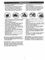
,_Look for this symbol to point out important safety precautions, tt means CAUTIONH! BECOME AWAREI!! YOUR SAFETY IS INVOLVED.
_,CAUTtON:
In order to prevent accidental starting when setting up, transporting,
adjusting or making repairs always disconnect spark plug wire and place wire where
it cannot contact spark plug.
Mow up and down slopes (15 ° Max), no
across.
, Remove obstacles such as rocks, tree
limbs, etc.
o Watch for holes, ruts, or bumps. Uneve_
terrain could overturn the machine. Talt
grass can hide obstacles.
Use slow speed. Choose a low gear so
that you will not have to stop or shift
while on the slope.
Avoid starting or stopping on a slope. If
tires lose traction, disengage the blade_
and proceed slowly straight down the
slope.
Do notturn on slopes unless necessa_
and then, turn slowly and gradually
downhill, ff possible.
A_.WARNING: The engine exhaust from
this product contains chemicals known to
the State of California to cause cancer,
birth defects, or other reproductive harm.
;_RODUCT
SPECmFICATtONS
)IL CAPACITY: 3,0 P_NTS
Should you experience any problem you
cannot easily remedy, please contact your
nearest Sears Authorized Service Center.
We have competent, well-trained technic
cians and the proper toots to service or
repair this tractor.
Please read and retain this manual. The
instructions will enable you to assemble
and maintain your tractor property. Always
observe the "SAFETY RULES".
GASOLINE
CAPACITY
AND TYPE:
1.25 GALLONS
UNLEADED
REGULAR
;PARK PLUG:
MAINTENANCE
31LTYPE
SAE 30 (above 32°F)
APFSF/SG/SH): SAE 5W-30
(below 32°F)
GAP: .030")
Champion JIgLM or
RJ19LM
STD361458
VALVE
CLEARANCE:
iNTAKE: .005"-.00T'
F__HAUST: .009"-,011"
GROUND SPEED
MPH):
FORWARD:
1ST
!.0
2ND
2.1
3RD
3.1
4 TM
4,0
5 TM
5.t
REVERSE:
TIRE PRESSURE:
1.8
FRONT: 14 PS!
REAR: !2 PSi
CHARGING
SYSTEM:
3 AMPS BATTERY
5 AMPS HEADUGHTS
BATTERY:
AMPiHR:
25
MIN. CCA: 190
CASE SIZE: UIR
BLADE 8OLT
TORQUE:
27-35 FT. LBS.
CONGRATULATIONS on your purchase
of a Craftsman Tractor. it has been
designed, engineered and manufactured
to give you the best possible dependability
and performance.
AGREEMENT
A Sears Maintenance Agreement is available on this product. Contact your nearest
Sears store for details,
CUSTOMER
RESPONS_BtLOTJES
o Read and observe the safety rules.
Follow a regular schedule in maintaining, caring for and using your tractor,
Follow the instructions under "Maintenance" and "Storage" sections of this
owner's manual.
_WARNING:
This tractor is equipped
with an internal combustion engine and
should not be used on or near any unimproved forest-covered, brush-covered or
grass-covered land unless the engine's
exhaust system is equipped with a spark
arrester meeting applicable local or state
laws (if any). If a spark arrester is used, it
should be maintained in effective working
order by the operator.
In the state of California the above is
required by law (Section 4442 of the
California Public Resources Code). Other
states may have similar taws. Federal
laws apply on federal lands. A spark
arrester for the muffler is available through
your nearest Sears Authorized Service
Center (See REPAIR PARTS section of
this manual).
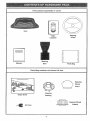
Parts Bag contents shown full size
Meta_
Screws
(2) Sheet
#10-16 x !/2
{1) Locknut
3/8-24
(1) Large Flat Washer
(1) Knob
(1) Shoulder
Bolt 5/16-18
(t) Washer
t7/32 × t-3/16 x 12 Gauge
Washers
(2) Lock t/4
(2) Hex Bolts t/4-20 x 3/4
d_/_
Nuts
(2)
Hex
1/4_20
9/32 × 5/8 × t6 Gauge
(2) Washers
6
Parts packed separately in car_on
Seat
Steering
Wheel
Video
Cassette
i
I
f
l
1
!
Steering
Boot
Manual
•
t
Parts Bag
Parts Bag contents not shown full size
Wheei
Steering
insert
Steering
Slope Sheet
Bushing
/
[_TT_
(2) Keys
Steering Wheel
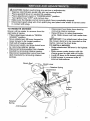
Your new tractor has been assembled at the factory with exception of those parts left
unassembled for shipping purposes. To ensure safe and proper operation of your tractc
all parts and hardware you assemble must be tightened securety. Use the correct tools
as necessary to insure proper tightness. Review the video cassette before you begin,
TOOLS REQUaRED FOR
ASSEMBLY
A socket wrench set will make assembly
easier. Standard wrench sizes you need
are listed below.
(1) 9116" wrench
(2) 7/18" wrenches
(2) 112" wrench
(t) Pliers
(1) Utility knife
(1) Tire pressure
(I) 5t16" wrench
gauge
When right or left hand is mentioned in
this manual, it means, from your point of
view, when you are in the operating position (seated behind the steering wheel).
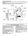
TO REMOVE
CARTON
TRACTOR
of steering wheel.
o Remove protective materials from trace,
tor hood and grill.
flMPORTANT: Check for and remove any
staples in skid that may puncture tires
where tractor is to roll off skid.
TO ROLL TRACTOR OFF SKiD (See
insert
._
3!8-24 Locknut
FROM
UNPACK CARTON
Remove all accessible loose parts and
parts boxes from shipping carton (See
page 6).
Cut, from top to bottom, along lines on
_,_ four comers of shipping carton, and
tay panels fiat.
* Check for any additional loose parts or
boxes and remove.
BEFORE ROLLING TRACTOR
SKiD
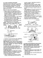
ATTACH STEeRiNG WHEEL
OFF
Slide the steering bushing over the
steering shaft.
o Raise steering shaft forward unti! screw
holes in dash line up with steering bushing. install two (2) sheet metal screws
and tighten securely.
_- Position steering boot over steering
shaft.
Place tabs of steering boot over tab
s_otsin dash and push down to secure.
Slide steering wheel adapter onto upper
steering shaft.
o Position front wheels of the tractor so
they are pointing straight forward.
o Position steering wheel so cross bars
are horizontal (left to right) and slide
onto adapter.
o Assembie large flat washer and 3/8-24
locknut and tighten securely.
Snap steering whee_ insert into center
Steering Wheet
Adapter __
Boot
_
Bushing
Tabs
_-_
Steenng
Steering Shaft
(Assembly
Position)
Steering
(ShippingShaft
Position)
_LL_b
_._
......... : , Tab Slot
Operation section for _locatlon and
function of controls)
r_ ....
lever p,u,,_, ,_,,_ raise attac_
ment lift lever to its highest position.
Release parking brake by depressing
clutch/brake pedal.
o Place gearshift lever in neutral (N) posi
tion.
o Roll tractor forward off skid.
o Remove banding holding discharge
guard up against tractor.
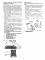
HOW TO SET UP YOUR
TRACTOR
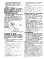
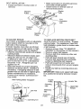
CONNECT BATTERY
_CAUTION:
Do not short battery terminals by allowing a wrench or any other
object to contact both terminals at the
same time. Before connecting battery, remove metal bracelets, wristwatch bands,
rings, etc. Positive terminal must be connected first to prevent sparking from accidenta_ grounding.
, Remove cardboard packing from seat
pan and lift seat pan to raised position.
o Open battery box door and remove protective plastic.
o Remove terminal protective caps and
discard.
o if this battery is put into service after
month and year indicated on label (label
Jocated between terminals) charge battery for minimum of one hour at 6-10
amps.
. First connect RED battery cable to posF
rive (+) terminal with hex bolt, flat washer, lock washer and hex nut as shown.
Tighten securely.
, Connect BLACK grounding cable to
negative (-) terminal with remaining hex
bolt, flat washer, lock washer and he×
nut. Tighten securely.
o Close battery box door. Open battery
box door for:
, Inspection for secure connections
(to tighten hardware).
o inspection for corrosion.
Testing battery.
Jumping (if required).
o Periodic charging.
Positive
Discard Terminal
(Red) Cable
Proctective
\
Caps
Lock Washer
Fiat Washer
Hex
He× Bolt
Negative
(Black)
Bakery
Door
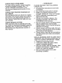
_NSTALL SEAT
Adjust seat before tightening adjustment
knob.
Remove cardboard packing on seat pan.
PLace seat on seat pan and assemble
shoulder bolt. Tighten shoulder bolt
securely.
Assemble adjustment knob and flat
washer Ioosety, Do not tighten.
o Lower seat into operating position and
sit on seat.
Slide seat until a comfortable position is
reached which allows you to press
clutch/brake pedal aHthe way down.
Get off seat without moving its adjusted
position.
Raise seat and tighten adjustment knob
securely.
Seat
Bolt
Seat Pan
_
Shoutder_
_
Adjustment Knob
"- Flat Washer
CHECK DECK LEVELNESS
For best cutting results, mower housing
should be properly leveled. See "TO
LEVEL MOWER HOUSING" in the
Service and Adjustments section of this
manua!.
J CHECKLtST
PLEASE REVIEW THE FOLLOWING
CHECKLIST:
J
J
/
CHECK FOR PROPER POSiTiON OF
ALL B_LTS
See the figures that are shown for replec o
ing motion and mower blade drive belts in
the Service and Adjustments sectoin of
this manual Verify that the belts are routed correctly.
CHECK BRAK_ SYSTEM
After you learn how to operate your traco
tot, check to see that the brake is properJy
adjusted. See "TO ADJUST BRAKE" in
the Service and Adjustments section of
this manual,
J
/
_/
#"
/
All assembly instructions have been
compfeted.
No remaining toose pa_s in carton.
Battery is properly prepared and
charged. (Minimum 1 hour at 6 amps).
Seat is adjusted comfortably and
tightened securely.
All tires are property inflated. (For
shipping purposes, the tires were
ovednflated at the factory).
Be sure mower deck is propedy teveie_
side-to-side/fronFto-rear
for beet
cutting results. (Tires must be properJy
inflated for leveling).
Check mower and drive belts, Be sure
they are routed properly around pul]ey_
and inside aHbeit keepers,
Check wiring. See that all connections
are still secure and wires are properly
clamped.
WHILE LEARNING HOW TO USE YOUR
TRACTOR, PAY EXTRAATTENTION TO
THE FOLLOWING IMPORTANT ITEMS:
_/ Engine oil is at proper _eveL
J Fuel tank is filled with fresh, clean,
regular unleaded gasoline.
#" Become familiar with all controls - their
location and function. Operate them
before you start the engine.
_" Be sure brake system is in safe
operating condition.
t0
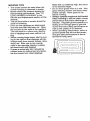
These symbols may appear on your tractor or in literature supplied with the product.
Learn and understand their meaning,
E3
BATTERY
CAUTION OR
WARNING
REVERSE
FORWARD
FAST
ENGINE ON
ENGINE OFF
OIL PRESSURE
LIGHTS ON
FUEL
CHOKE
MOWER HEIGHT
PARKING BRAKE
LOCKED
SLOW
OVER TEMP
LIGHT
UNLOCKED
MOWER LIFT
L
ATTACHMENT
CLUTCH ENGAGED
NEUTRAL
ATTACHMENT
CLUTCH DISENGAGED
IGNITION
DANGER,
REVERSE
KEEP
HANDS
AND
FEET
HIGH
LOW
KEEP AREA CLEAR
PARKING BRAKE
SLOPE HAZARDS
(SEE SAFETY RULES SECTION)
HYDROSTATIC FREE WHEEL
(Hydro Models onPy)
AWAY
11
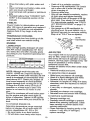
KNOWYOUR
TRACTOR
READ THiS OWNER'S MANUAL AND SAFETY RULES BEFORE OPERATmHG YOUI:
TRACTOR
Compare the illustrations with your tractor to familiarize yourself with the locations of
various controls and adjustments. Save this manual for future reference.
Attachment
Clutch Lever
Light
ignition
Switch
ThrottleChoke
Control
Lift Lever
Plunger
Attachment
C|utch/Brake
Pedal
Lift
N
Gearshift
Lever
ParkJngBrake
l
Our tractors conform to the safety standards of the American
National Standards institute,
GEARSHIFT LEVER: Selects the speed
and direction of tractor.
ATTACHMENT LiFT LEVER: Used to
raise, lower, and adjust the mower deck o,
other attachments mounted to your tracte_
LiFT LEVI_R PLUNGER: Used to reteas_
attachment lift _ever when changing its
position.
iGNiTiON SWITCN: Used for starting an_
stopping the engine.
ATTACHMENT CLUTCH LEVER: Used
to engage the mower blades, or other
attachments mounted to your tractor.
LIGHT SWITCH: Turns the headJights on
and off.
THRO_LFJCHOKE
CONTROL: Used
for starting and controfling engine speed.
CLUTCHJSRAK_ PEDAL: Used for
declutching and braking the tractor and
starting the engine.
PARKING 13RAKE: Locks clutch/brake
peda_ into the brake position°
!2
Theoperatiori
ofanytractorcanresultinforeignobjects
thrown
intothe
es or eye shields while operating your tractor or performing any adjusteyes,which
canresult
Always
wear
safety
glassments
or repairs.
We insevere
recommendeyea damage.
wide vision
safety
mask
over
the
spectacles, or standard safety glasses.
HOW TO USE YOUR TRACTOR
Your tractor is equipped with an operator
presence sensing switch. When engine
is running, any attempt by the operator to
leave the seat without first setting the
parking brake will shut off the engine.
TO SET PARKING BRAKIE
o Depress clutch/brake pedal into fuit
"BRAKE" position and hold,
o Place parking brake lever in
"ENGAGED" position and release pressure from clutch/brake pedal, Pedal
should remain in "BRAKE" position.
Make sure parking brake will hold tractor secure.
Attachment Clutch Lever
NOTE: Under certain conditions when
tractor is standing idle with the engine running, hot engine exhaust gases may
cause "browning" of grass. To eliminate
this possibility, always stop engine when
pping tractor on grass areas.
CAUTION: Always stop tractor completely, as described above, before leaving
the operator's position; to empty grass
catcher, etc,
THROTTLE CONTROL
AJways operate engine at furl throttle.
Operating engine at less than full throttle reduces the battery charging rate.
o Full throttle offers the best bagging and
mower performance,
Engaged" Position
Throttle/Choke
/_
TO MOVE FORWARD AND BACKWARD
The direction and speed of movement is
ControIlever
__,,_
_K__j"Disengaged"
controlled by the gearshift lever.
Position
Clutch/Br__
Start tractor with clutch/brake pedal
Parking
depressed and gearshift lever in neutral
Broke
Position
(N) position.
/
"Engaged"
Move gearshift lever to desired position.
Position
Slowly release clutct-_brake pedal to
_
Gearshift
start movement,
Lever
°Disengaged" _F _
"Brake" I_osition
IMPORTANT: Bring tractor to a complete
Position
stop before shifting or changing gears.
STOPPING
Failure to do so will shorten the useful life
MOWER BLADES of your transaxte
To stop mower blades, move attachTO ADJUST MOWER CUTTING HEIGHT
ment clutch lever to "DISENGAGED"
The position of the attachment lift lever
position.
determines the cutting height,
GROUND DRIVE o Grasp lift lever.
To stop ground drive, depress
o Press plunger with thumb and move
clutch/brake pedal into furl "BRAKE"
lever to desired position,
position.
The cutting height range is approximateo Move gearshift lever to neutral (N) posily 1-1/2 to 4". The heights are measured
tion.
from the ground to the blade tip with the
ENGINE engine not running. These heights are
o Move throttle control to slow position.
approximate and may vary depending
NOTE: Failure to move throttle control to
upon soil conditions, height of grass and
slow position and al!owing engine to id!e
types of grass being mowed.
before stopping may cause engine to
The average lawn should be cut to
"bac_ire =,
approximately 2ol/2 inches during the
o Turn ignition key to "OFF" position and
cool season and to over 3 inches during
remove key, Always remove key when
hot months. For heaJthier and better
Ieaving tractor to prevent unauthorized
_ooking fawns, mow often and after
use.
moderate growlh.
" Never use choke to stop engine.
I3
Forbestcutting
performance,
grass
over6 inches in height should be
When pushing or towing your tractor, b_
sure gearshift lever is in neutral (N)
position.
o Do not push or tow tractor at more thar_
five (5) MPH.
NOTE[: To protect hood from damage
when transporting your tractor on a truck
or a trailer, be sure hood is closed and
secured to tractor. Use an appropriate
means of tying hood to tractor (rope, cord
etc.).
mowed twice. Make the first cut relax
tiveiy high; the second to desired
height.
TO OPERATE MOWER
Your tractor is equipped with an operator
presence sensing switch. Any attempt by
the operator to leave the seat with the
engine running and the attachment clutch
engaged will shut off the engine.
Select desired height of cut.
Start mower bJades by engaging attachment clutch control.
- TO STOP MOWER BLADES - disen_gage attachment clutch control.
CAUTmON: Do not operate the mower
without either the entire grass catcher, on
mowers so equipped, or the discharge
guard in place.
Attachment
Lift Lever
High Position
Attachment
Lift
Lever
BEFORE
Low
Position
High Position
"Disengaged"
Position
STARTING
THE ENGINE
CHECK ENGINE OIL LEVEL
• The engine in your tractor has been
shipped, from the factory, already filled
with summer weight oil
Check engine oil with tractor on level
ground.
Remove oil fiil cap/dipstick and wipe
dean, reinsert the dipstick and screw
cap tight, wait for a few seconds,
remove and read oiQlevel If necessar_j
add oil until "FULL" mark on dipstick is
reached. Do not overfill
• For cold weather operation you should
change oil for easier starting (See "OIL
VISCOSITY CHART" in the Maintenance section of this manual).
o To change engine oil, see the Mainten-.
ance section in this manual.
Discharge
Guard
ADD GASOUNE
o Fill fuel tank. Use fresh, clean, regular
unleaded gasoline with a minimum of
87 octane. (Use of leaded gasoline wil_
increase carbon and lead oxide
deposits and reduce valve life). Do not
mix oil with gasoline. Purchase fue! in
quantities that can be used within 30
days to assure fuel freshness.
IMPORTANT: When operating irr temper_
tures below 32°F(0°C), use fresh, clean
winter grade gasoline to help insure good
dAweather starting.
RNtNG: Experience indicates that
alcohol blended fuels (called gasohol or
using ethanol or methanol) can attract
moisture which leads to separation and
formation of acids during storage. Acidic
gas can damage the fuel system of an
engine whi_e in storage. To avoid engine
problems, the fuel system should be emp
tied before storage of 30 days or longer.
Drain the gas tank, start the engine and
let it run until the fuel Jines and carbureto_
_reempty. Use ,_reshfuet next season.
TO OPERATE ON HALLS
_.CAUTION:
Do not drive up or down
hills with slopes greater than 15° and do
not drive across any slope, A slope guide
at the back of your manual is provided for
your use.
Choose the slowest speed before starting up or down hills.
o Avoid stopping or changing speed on
hills,
if slowing is necessary, move throttle
control lever to slower position.
* if stopping is absolutely necessary,
push clutch/brake pedal quickly to brake
position and engage parking brake.
o Move gearshift lever to 1st gear. Be
sure you have allowed room for tractor
to roll slightly as you restart movement.
o To restart movement, slowly release
parking brake and clutchJbrake pedal.
Make all turns slowly.
TO TRANSPORT
o Raise attachment lift to highest position
with attachment lift control
14
SeeStorage
instructions
foradditional
information.
Neveruseengine
orcarburetorc{eaner
products
inthefueltankorpernentdamage
mayoccur.
CAUTION: Fill to bottom of gas tank
filler neck. Do not overfill Wipe off any
spilled oil or fuel. Do not store, spill or use
gasoline near an open flame.
TO STABT ENGINE
When starting the engine for the first time
or if the engine has run out of _uel, it will
take extra cranking time to move fuel from
the tank to the engine.
Sit on seat in operating position,
depress clutch/brake pedal and set
parking brake.
- Piece gear shift lever in neutral (N) position.
Move attachment clutch to "DISENGAGED" position.
o Move throttle control to choke position.
NOTE: Before starting, read the warm
and cold starting procedures below.
= insert key into ignition and turn key
clockwise to "START" position and
release key as soon as engine starts.
Do not run starter continuously for more
than fifteen seconds per minute. |f the
engine does not start after several
attempts, move throttle control to fast
position, wait a few minutes and try
again. If engine etitl does not start,
move the throttle control back to the
choke position and retry.
WARM WEATHER STARTING (50 ° F and
above)
• When engine starts, move the throttle
control to the fast position.
The attachments and ground drive can
now be used, if the engine does not
accept the load, restart the engine and
allow it to warm up for one minute using
the choke as descdbed above.
COLD WEATHER STARTING ( 50 ° F AND
BELOW)
When engine starts, allow engine to run
with the throttle control in the choke
position until the engine runs roughly,
then move throttle control to fast position. This may require an engine warmup pedod from several seconds to several minutes, depend}ng on the temper_
ature.
, The attachments can also be used during the engine warm-up period.
NOTE: if at a high altitude (above 3000
feet) or in cold temperatures (below 32 F)
the carburetor fuel mixture may need to be
adjusted for best engine performance.
See "TO ADJUST CARBURETOR _ in the
Service and Adjustments section of this
manual.
NOTE: At a high altitude (above 3000
feet) or in cotd temperatures (beBow 32 F)
the carburetor fue_ mixture may need to be
adjusted for best engine performance.
See "TO ADJUST CARBURETOR" in the
Service and Adjustments section of this
manual.
!5
MOWING
TraPS
o
-
-
*
Tire chains cannot be used when the
mower housing is attached to tractor.
Mower should be prepedy leveled for
best mowing performance. See "TO
LEVEL MOWER HOUSING" in the
Service and Adjustments section of this
manual.
The left hand side of mower should be
used for trimming.
Drive so that clippings are discharged
onto the area that has been cut. Have
the cut area to the right of the machine.
This will result in a more even distribu_
tion of clippings and more uniform cutting.
When mowing large areas, start by turning to the right so that clippings will discharge away from shrubs, fences, driveways, etc. After one or two rounds,
mow in the opposite direction making
taft hand turns until finished
If grass is extremely tall, it should be
mowed twice to reduce load and possible fire hazard from dried clippings.
16
Make first cut relatively high; the secon
to the desired height.
o Do not mow grass when it is wet. Wet
grass will plug mower and leave undesirabie clumps. Allow grass to dry
before mowing.
o Always operate engine at fuJ! throttl_
when mowing to assure better mowin!
performance and proper discharge of
material. Regulate ground speed by s_
lecting a low enough gear to give the
mower the best cutting performance a_:
well as the quality of cut desired.
When operating attachments, select a
ground speed that wilJ suit the terrain
and give best performance of the attachment being used.
t1,1
CUSTOMER RESPONSgBILmES
- l_ eq_J_ppe,d
with
G_N_FIAL
o_| n_t,
ehmnge
o_1 every
,_o
hou;,'e,
RECO_MENDATIIONS
The warranty on this tractor does not cover
items that have been subjected to operator
abuse or negligence. To receive ful! value
from the warranty, operator must maintain
tractor as instructed in this manual. Some
adjustments will need to be made periodically to properly maintain your tractor.
Atl adjustments in the Service and
Adjustments section of this manual should
be checked at least once each season.
Once a year you should replace the
spark plug, clean or replace air filter, and
check blades and betts for wear. A new
spark ptug and clean air filter assure
proper air-fuel mixture and help your
engine run better and last longer.
B_FOR_
_ACH
US_
o Check engine oil level.
Check brake opeFation.
o Check tire pressure.
Check operator presence and interlock
systems for proper operation.
Check for _oose fasteners.
Front
Front Wheel
Wheel
Bearing
Zerk
Bearing Zerk
Engine
@ Attachment i
clu c,
i
Pivot(s)
i
,
=
i
i
I
@ SAE 30 or I0w30 Moto{ OIL
@ Genera_Purpose Grease
@ Referto Maintenance Engine" Section
_PO_TANT:
Do not oil or grease the
pivot points which have special nylon bearings. Viscous lubricants will attract dust
and dirt that will shorten the life of the selflubricating bearings, tf you feel they must
be iubricated, use only a dry, powdered
graphite type _ubricant sparingly.
17
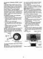
TO SHARPEN BLADE
NOTE: We do not recommend sharpen!n!
biade, but if you do, be sure the blade is
balanced.
Care shouJd be taken to keep the blade
balanced. An unbalanced blade witl caus_
excessive vibration and eventual damage
to mower and engine.
= The blade can be sharpened with a file
or on a grinding wheel. Do not attempt
to sharpen while it is on the mower.
To check btade balance, you will need
5/8" diameter steel bolt, pin, or a cone
balancer. (When using a cone balance_
follow the instructions supplied with bai
ancer).
NOTE: Do not use a nail for balancing
blade. The lobes of the center hole may
appear to be centered, but are not.
Slide blade onto an unthreaded portior_
of the steel bolt or pin and hold the bolt
or pin para!iel with the ground. If blade
is bafanced, it should remain in a horizontal position. If either end of the biad
moves downward, sharpen the heavy
end until the blade is balanced.
Center Hole
TRACTOR
Always observe safety rules when performing any maintenance.
BRAKE OPERATION
if tractor requires more than six (8) feet
stopping distance at high speed in highest
gear, then brake must be adjusted. (See
"TO ADJUST BRAKE" in the Service and
Adjustments section of this manual).
TtRES
Maintain proper air pressure in all tires
(See =PRODUCT SPECIFICATIONS"
on page 5 of this manual).
Keep tires free of gasoline, oil, or insect
control chemicals which can harm rubber.
• Avoid stumps, stones, deep ruts, sharp
objects and other hazards that may
cause tire damage.
NOTE: To seal tire punctures and prevent
flat tires due to slow leaks, tire sealant
may be purchased from your local parts
dealer. Tire sea_ant atso prevents tire dry
rot and corrosion.
BLADE CARE
For best results mower blades must be
kept sharp. Replace bent or damaged
blades.
6LADE REMOVAL
Raise mower to highest position to atiow
access to blades.
Remove hex bolt, tock washer and fiat
washer securing btade.
, Install new or resharpened blade with
trailing edge up towards deck as shown.
o Reassemble hex bolt, lock washer and
fiat washer in exact order as shown.
= Tighten bolt securely (27-35 Ft. Lbs.
torque).
!MPORTANT:
treated.
B_ade
BATTERY
"{our tractor has a battery charging syste_
which is sufficient for normal use. Howev
er, periodic charging of the battery with al
automotive charger will extend its life.
Keep battery and terminals clean.
Keep battery bolts tight.
® Keep small vent holes open. _"
Recharge at 6-10 amperes for 1 hour.
NOTE: The originai equipment battery or
your tractor is maintenance free. Do not
attempt to open or remove caps or cove_
Adding or checking level of electrolyte is
not necessary.
TO CLEAN BATTERY AND TERMINALS
Blade boil is Grade 8 heat
Assembly
Bladle_r_.._
Fiat Was
Mandrel
Tra}ting
Edge Up
Hex Bolt (Grade
"A Grade 8 heat treated bolt can be
identified by six lines on the bott head.
Corrosion and dirt on the battery and tar-.
minats can cause the battery to "leak"
power.
, Remove terminal guard.
Disconnect BLACK battery cable first
then RED battery cable and remove
ba_e_y from tractor.
18
Catch oil in a suitab|e container.
o Remove oil fill cap/dipstick. Be careful
not to allow dirt to enter the engine
when changing oil.
Remove drain plug.
After oil has drained completely, replace
oil drain ptug and tighten securely.
Refit! engine with oil through oil fill dipstick tube. Pour slowly. Do not overfill.
For approximate capacity see "PRODUCT SPECIFICATIONS" on page 5 of
this manual
- Use gauge on oil fill cap/dipstick for
checking level Be sure dipstick cap is
tightened securely for accurate reading.
Keep oi_at "FULL" tine on dipstick,
Rinse the battery with plain water and
dry.
Clean terminals and battery cable ends
with wire brush until bright.
Coat terminals with grease or petroleum
jelly.
o Reinstal battery.(See "CONNECT BATTERY" in the Assembly section of this
manual).
VoBELTS
Check V-belts for deterioration and wear
after 100 hours of operation and replace if
necessary, The belts are not adjustable,
Replace hefts _ they begin to slip from
weal.
TRANSAXLE COOLING
Keep transaxle free from build-up of dirt
and chaff which can restrict cooling.
oilFill
.___CaplDipstick
ENGIINtE
Oil Drain
LUBRICATION
Only use high quality detergent oil rated
with APt service classification SF, SG or
SH. Select the oil's SAE viscosity grade
according to your expected operating temperature.
Plug
AIR FILTER
Your engine will not run properly using a
dirty air filter. Clean the foam pro-cleaner
after every 25 hours of operation or every
season. Service paper cartridge every I00
hours of operation or every season,
whichever occurs first.
Service air cleaner more often under dusty
conditions.
Remove knob(s) and cover.
TO SERVICE PRE-CLEANER
NOTE: Although multi_viscosity oils
(5W30, 10W30 etc.) improve starting in
cold weather, these multi-viscosity oils will
result in increased oil consumption when
used above 32°E Check your engine oil
_evel more frequently to avoid possible
engine damage from running low on o11.
Change the oil after every 25 hours of
operation or at least once a year if the
tractor is not used for 25 hours in one
year.
Check the crankcase oil tevei before starting the engine and after each eight (8)
hours of operation, Tighten oi! fill cap/dipstick securely each time you check the oil
level
Stide foam pro-cleaner off cartridge.
® Wash it in liquid detergent and water.
Squeeze it dry in a clean cloth.
Saturate it in engine oil Wrap it in cJean,
absorbent c!oth and squeeze to remove
excess oil
o I_very dirty or damaged, replace precleaner,
o Reinstall pro=cleaner over cartridge.
Reinstall cover and secure with knob(s).
TO SERVICE CARTRIDGE
o Remove cartridge nut.
Carefully remove cartridge to prevent
debris from entering carburetor. Clean
base carefully to prevent debris from
entering carburetor_
o Clean cartridge by _apping gently on flat
surface. If very dirty or damaged,
replace cartridge.
TO CHANGE ENGINE OiL
Determine temperature range e×pected
before oi! change, A!I oil must meet API
service classification SF, SG or SH.
Be sure tractor is on level surface.
Oil wiii drain more freely when warm°
19
®Reinsta!l
cartridge,
nut,prec_eaner,
coverandsecure
withknob(s).
mMPORTANT:
Petroleum
solvents,
suchas
kerosene,
are not to be used to clean the
cartridge. They may cause deterioration of
the cartridge. Do not oi! cartridge. Do not
use pressurized air to clean or dry cartridge.
Cover
Knob
Cartridge
CLEAN AiR SCREEN
Air screen must be kept free of dirt and
chaff to prevent engine damage from overheating. Clean with a wire brush or compressed air to remove dirt and stubborn
dried gum fibers.
ENGINE COOLING FiNS
Remove any dust, dirt or oil from engine
cooling fins to prevent engine damage
from overheating.
• Remove screws from blower housing
and lifl housing and dipstick tube
assembly off engine.
, Cover oil lilt opening to prevent entry of
dirt.
o Use compressed air or stiff bristle brush
_o thoroughly clean engine cooling fins.
o To reassemble, reverse above procedure.
Screws
Blower P
MUFFLER
Inspect and replace corroded muffler and
spark arrester (if equipped) as it could cre
ate a fire hazard and/or damage.
SPARK PLUGS
Repiace spark plugs at the beginning of
each mowing season or after every 100
hours of operation, whichever occurs first.
Spark plug type and gap setting are
shown in "PRODUCT SPECIFICATIONS"
on page 5 of this manual.
IN-LINE FUEL FILTER
The fuel filter should be replaced once
each season. If fuel filter becomes
dogged, obstructing fuel flow to carburetor, replacement is required.
• With engine cool, remove filter and ptu_
fuel line sections.
, Place new fuel filter in position in fuel
line with arrow pointing towards carbu*
retor.
Be sure there are no fuel line leaks and
clam.
CLEANING
Clean engine, batteR_',seat, finish, etc.
of all foreign matter.
Keep finished surfaces and wheels fre_
of all gasoline, oil, etc.
_. Protect painted surfaces with automotive type wax.
We do not recommend using a garden
hose to dean your tractor unless the eiec
trical system, muffler, air filter and carbur_
tot are covered to keep water out. Water
in engine can result in a shortened engin,
life.
Plug
20
A_,CAUTmON: Before performing any service or adjustments:
o Depress clutch/brake pedal fully and set parking brake,
o Place gearshift tever in neutral (N) position.
, Place attachment clutch in =DISENGAGED _ position.
Turn ignition key "OFF' and remove key,
Make sure the blades and aU moving parts have completely stopped.
Disconnect spa_k plug wire from spark plug and place wire where it cannot come
in contact with plug,
TO REMOVE MOWER
Mower will be easier to remove from the
right side of tractor.
Place attachment clutch in "DISENGAGED" position.
* Move attachment lift lever forward to
lower mower to its lowest position.
, Roll belt off engine pulley.
Disconnect clutch rod from clutch lever
by removing retainer spdng.
, Disconnect anti-swaybar from chassis
bracket by removing retainer spring.
o Disconnect suspension arms from rear
deck brackets by removing retainer
spdngs,
Clutch Rod
Disconnect front links from deck by
removing retainer springs.
, Raise lift Jever to raise suspension
arms. Slide mower out from under tractor.
IMPORTANT: ff an attachment other than
the mower deck is to be mounted on the
tractor, remove the front links.
TO _NSTALL MOWER
, Raise attachment lift lever to its highest
position.
Slide mower under tractor with discharge guard to right side of tractor.
Lower lift lever to its lowest position.
install mower in reverse order of
removal instructions.
Clutch Lever
Spnng
Suspension
Arms
Front
Link
//
.,.
Spring
Retainer
/
Ant_-Swaybar
21
Engine
Pulley
TO LEVEL MOWER HOUSING
equal in length. Both links should be
approximately 10-318".
- tf links are not equal in length, adjust
one link to same length as other link.
To lower front of mower loosen nut "E"
on both front links an equal number of
turns.
When distance "D" is 1/8" to 1/2" lower
at front than rear, tighten nuts "F"
against trunnion on both front links.
To raise front of mower, loosen nut "F"
from trunnion on both front links.
Tighten nut "E" on both front linksan
equal number of turns.
When distance "D" is !/8" to 1/2" lower
at front than rear, tighten nut "F against
trunnion on both front |inks.
Recheck side-to-side adjustment.
Adjust the mower while tractor is parked
on level ground or driveway. Make sure
tires are properly inflated (See "PRODUCT SPECIFICATIONS").
If tires are
over or underinflated, you wiBlnot properly
adjust your mower.
SIDE-TO-SIDE ADJUSTMENT
Raise mower to its highest position.
At the midpoint of both sides of mower,
measure height from bottom edge of
mower to ground. Distance "A" on both
sides of mower should be the same or
within t/4" of each other.
if adjustment is necessary, make adjustment on one side of mower on_y.
* To raise one side of mower, tighten lift
link adjustment nut on that side.
= To lower one side of mower, loosen tift
link adjustment nut on that side.
NOTE:
Each full turn of adjustment nut
will change mower height about I/8".
Bottom
_
Bottom
\
Mandrel
Both Front LinksShould be Equalin Length
....
Suspension
Trunnion
Recheck measurements after adjusting.
FRON%TO-BACK ADJUSTMENT
RMPORTANT: Deck must be level side-to=
s,de. _, _h_ ,O,,_,,,h,_ ,r .... oh,oba_k adjustment is necessary, be sure to adjust both
front links equally so mower will stay
level side-to-s_de.
Front Links
TO REPLACE MOWER 8LADE DRIVE
BELT (See illustration Next Page)
The mower blade drive belt may be
replaced without tools. Park the tractor on
level surface. Engage parking brake.
BELT REMOVAL -
To obtain the best cutting results, the
mower housing should be adjusted so that
the front is approximately 1/8" to !/2"
lower than the rear when the mower is in
its highest position.
Check adjustment on right side of tractor.
Measure distance "D" directly in front and
behind the mandrel at bottom edge of
mower housing as shown.
Before making any necessary, adjustmen&s, c!_eck tha_ bo_h _ront
Ii_;<s
_re
Remove mower from tractor (See 'q'O
REMOVE MOWER" in this section of
this manual).
Work be_ off both mandret pulleys and
idler
pulleys.
• P_il bei_ away from mower.
22
BELT iNSTALLATION _
o Install new belt in reverse order of
removal
MandreJ
- Make sure belt is in all pulley grooves
and inside all belt guides.
• install mower in reverse order of
removal instructions.
td_er
Put}eys ....
\__:,
Engine
J"Pulty
",,,_"_Supention
Retainer
TO ADJUST BRAKE;
Your tractor is equipped with an adjustabJe
brake system which is mounted on the
right side of the transaxte.
if tractor requires more than six (6) feet
stopping distance at high speed in highest gear, then brake must be adjusted.
, Depress clutch!brake pedal and engage
parking brake.
, Measure distance between brake operating arm and nut "A" on brake rod.
, if distance is other than t-1/2", loosen
jam nut and turn nut "A" until distance
becomes !-1/2". Retighten jam nut
against nut "A".
, Road test tractor for proper stopping
distance as stated above. Readjust if
necessary, ff stopping distance is still
greater than six (6) feet in highest gear,
further maintenance is necessary.
Contact your nearest authorized service center.
TO REPLACE MOTION ORIVE BELT
Park the tractor on level surface. Engage
parking brake. For assistance, there is a
belt installation guide decal on bottom sid_
of |eft footrest.
Remove mower (See "TO REMOVE
MOWER" in this section of this manual.)
o Remove upper belt keeper.
Remove belt from stationary idler and
cfutching idler,
, Pull belt slack toward rear of tractor.
Remove belt upwards from transaxle
pulley by deflecting belt keepers.
o Pull be{t toward front of tractor and
remove downwards from around engine
pulley.
, install new belt by reversing above procedure.
tMPOFITANT: Make sure upper be_t keeper is positioned properly between locater
tab.
Engine
Putiey
With Parking Brake "Engaged"
Clutching
idler
Stationa@
Idler
Transaxle,
PuItey
23
Upper Belt
Keeper
TO ADJUST STEERING WHEEL AUGNMENT
If steering wheel crossbars are not hodzontal (left to right) when wheels are positioned straight forward, remove steering
wheel and reassemble per instructions in
the Assembly section of this manual.
FRONT WHEEL TOE4NICAMBER
The front wheel toe-in and camber are not
adjustable on your tractor, if damage has
occurred to affect the front wheel toe-in or
camber, contact your nearest authorized
service center.
TO REMOVE WHEEL FOR REPAIRS
• Block up axle secureJy.
, Remove axle cover, retaining ring and
washers to allow wheel removal (rear
wheel contains a square key = Do not
lose).
= Repair tire and reassemble.
• On rear wheels only: align grooves in
rear wheel hub and axle. insert square
key.
Replace washers and snap retaining
ring securely in axle groove.
Replace axte cover.
NOTE: To seal tire punctures and prevent
flat tires due to slow leaks, tire sealant
may be purchased from your local parts
dealer. Tire sealant also prevents tire dry
rotand corrosion.
and smoking materials away from batteries. Always wear eye protection when
around battedes.
tf your battery is too weak to start the
engine, it should be recharged, tf "jumper
cables" are used for emergency starting,
follow this procedure:
iMPORTANT: Your tractor is equipped
with a 12 volt negative grounded system.
The other vehicle must also be a 12 volt
negative grounded system. Do not use
your tractor battery to start other vehic_eso
TO ATTACH JUMPER CABLES
• Connect each end of the RED cable to
the POSITIVE (+) terminal of each bat*
tory, taking care not to short against
chassis.
, Connect one end of the BLACK cable t_
the NEGATIVE (-) terminaJ of fulty
charged battery.
• Connect the other end of the BLACK
cable to good CHASSIS GROUND,
away from fuel tank and battery.
TO REMOVE CABLES, REVERSE
ORDER , Remove BLACK cable first from chassi
and then from the fully charged battery.
- Remove RED cable last from both bat*
reties.
Positive Terminal
Negative Terminal
Washers
Retaining
Ring
f
Axle Cover
'_\-_.. Square Key
(Rear Wheel Only)
TO START F_NGINE THAT HAS A WEAK
BATTERY
_CAUTJON:
Lead-acid batteries generate explosive gases. Keep sparks, [flame
Positive Terminal
Negative Te nnir,_,
24
TO REPLACE HEADLIGHT BULB
o Raise hood.
* Pu{l bulb holder out of the hole in the
backside of the grill.
Replace bulb in holder and push bulb
holder securely back into the hole in the
backside of the grill.
Close hood.
INTERLOCKS AND RELAYS
Loose or damaged wiring may cause your
tractor to run poody, stop running, or prevent it from starting.
, Check wiring. See electrical wiring diagram in the Repair Parts section of this
manual,
TO REPLACE FUSE
Replace with 30 amp automotive-type
plug-in fuse. The fuse holder is located
behind the dash.
TO REMOVE HOOD AND GRILL
ASSEMBLY
Raise hood.
Unsnap headlight wire connector.
- Stand in front of tractor. Grasp hood at
sides, tilt toward engine and _ift off of
tractor.
To replace, reverse above procedures.
ENGRNE
Maintenance, repair, or replacement of th_
emission control devices and systems,
which are being done at the customers
expense, may be performed by any nonroad engine repair establishment or individual Warranty repairs must be performed by an authorized engine manufac_.
turer's service outlet.
TO ADJUST THROTTLE CONTROL
CABLE
The throttle control has been preset at the
factory and adjustment should not be nec,_
essary. Check adjustment as described
below before loosening cable, if adjust_
ment is necessary, proceed as follows:
With engine not running, move throttle
control lever from slow to choke posiGovernor
Governor
Control Lever
Control Plate
\
\
Clamp
Screw
Holes "A"
Throttle
Cable
Hood /
Headlight
Wire
Connector
tion. Slowly move lever from choke to
fast position.
Check that holes "A" in governor control
lever and hole in governor plate line-up.
If holes "A" are not aligned, loosen
clamp screw and move throttle cable
until holes are aligned. Tighten clamp
screw securely,
25
TO ADJUST CARBURETOR
NOTE: The carburetor on this engine }s
tow emission. It is equipped with an idle
fuel adjusting needle with a {imiter cap,
which allows some adjustment within the
limits aUowed by the cap. Do not attempt
to remove the limiter cap. The ;imiter cap
cannot be removed without breaking the
adjusting needle.
The carburetor has been preset at the factory and adjustment should not be neces_
sary. However, minor adjustment may be
required to compensate for differences in
fuel, temperature, altitude or load. if the
carburetor does need adjustment, proceed
as follows:
in general, turning idle mixture vatve in
(clockwise) decreases the supply of fuel to
the engine giving a leaner fuel/air mixture.
Turning the idle mixture valve out
'.... '^-^'^^_ .... _ increases the supply of
fuel to the engine giving a richer fueVair
mixture,
IMPORTANT: Damage to the needle valve
and the seat in carburetor may result if
screw is turned in too tight.
PRELIMINARY SETTING -
® Whi_e still holding throttle lever against
idle speed screw, turn idle mixture valv,
full travel clockwise then counterciock._
wise unti_ engine Funs rough. Turn valw
to a point midway between those two
positions. Release throttle fever.ACCE_
ERATION TEST • Move throttle control lever from slow to
fast position. If engine hesitates or die_
turn idle mixture valve out (counter°
clocicwise) 1/8 turn. Repeat test and
continue to adjust, if necessary, until
engine accelerates smoothly.
High speed stop is factory adjusted. Do
not adjust--damage
may result.
_MPORTANT: Never tamper with the
engine governor, which is factory set for
proper engine speed, overspeeding the
engine above the factory high speed setting can be dangerous, if you think the
engine-governed high speed needs
adjusting, contact your nearest authorize,
service center, which has proper equipment to make any necessary adjustment:
Idle Speed
Screw
Throttle
Lever
o Air cleaner assembty must be assembled to the carburetor when making carburetor adjustments.
• Be sure the throttle control cable is
adjusted property (see above).
FINAL SETTING , Start engine and allow to warm for five
minutes. Make final adjustments with
engine running and shift/motion control
lever in neutral (N) position.
• Move throttle control lever to slow position. With finger, rotate and hold throttle
lever against idle speed screw. Turn idle
speed screw to attain !750 RPM.
ldle/Mixture_
ValveWith
Limiter
26
_ if
immediately prepare your tractor for storage at the end of the season or if the tractor will not be used for 30 days or more.
,_CAUTtON:
Never store the tractor with
gasoline in the tank inside a building
where fumes may reach an open flame or
spark. Allow the engine to cool before storing in any enclosure.
TRACTOR
Remove mower from tractor for winter
storage. This wil! allow you to clean it thoreughty. Remove atl dirt, grease, _eaves,
etc. Store in a clean, dry area.
Clean entire tractor (See "CLEANING" in
the Maintenance section of this manuai).
* Inspect and replace belts, if necessary
(See belt replacement instructions in the
Service and Adjustments section of this
manual).
Lubricate as shown in the Maintenance
section of this manual.
o Be sure that all nuts, bolts and screws
are securely fastened, inspect moving
parts for damage, breakage and wear.
Replace if necessary.
Touch up all rusted or chipped paint surfaces; sand lightly before painting.
BATTERY
Fully charge the battery for storage,
o After a period of time in storage, battery
may require recharging.
To help prevent corrosion and power
leakage during long pedods of storage,
battery cables should be disconnected
and battery cleaned thoroughly (see "TO
CLEAN BATTERY AND TERMINALS" in
the Maintenance section of this manua 0.
o After cleaning, teave cables disconnected and place cables where they cannot
come in contact with battery terminafs.
o If battery is removed from tractor for
storage, do not store battery directly on
concrete or damp sudaceso
ENGINE
FUEL SYSTEM
IMPORTANT: it is important to prevent
gum deposits from forming in essential fuel
system parts such as carburetor, fuel filter,
fuel hose, or tank during storage. Also,
experience indicates that aicohot btended
27
fuels (called gasohol or using ethanol or
methanol) can attract moisture which
leads to separation and formation of acid_
during storage. Acidic gas can damage th_
rued system of an engine while in storage.
Drain the fue_ tank.
Start the engine and let it run untin the
fuel Jines and carburetor are empty.
Never use engine or carburetor cleaner
products in the fuel tank or permanent
damage may occur.
Use fresh fuel next season.
NOTE: Fuet stabilizer is an acceptable
alternative in minimizing _he formation of
fue_ gum deposits dutfng storage. Add stabilizer to gasoline in fueJ tank or storage
container. Always re{tow the mix ratio
found on stabilizer container. Run eng{ne
at least 10 minutes after adding stabilizer
to al!ow the stabilizer to reach the carburetor, Do not drain the gas tank and carburetor if using fuel stabilizer.
ENGINE OIL
Drain oil (with engine warm) and replace
with clean engine oil (See "ENGINE" in
the Maintenance section of this manual).
CYLItNDER
Remove spark plug(s),
Pour one ounce of oil through spark
plug hole(s) into cylinder(s).
, Turn ignition key to "START" posffion for
a few seconds to distribute oil.
• Replace with new spark plug(s).
OTHER
Do not store gasoline from one season
to another.
Replace your gasoline can if it starts to
rust. Rust and!or dirt in your gasoBne
will cause problems.
o If possible, store your tractor indoors
and cover it to give protection from dust
and dirt.
Cover your tractor with a suitable pro°
tective cover that does not retain moisture. Do not use plastic. Plastic cannot
breathe, which allows condensation to
form and cause your tractor to rust.
0MPOF_TANT: Never cover tractor while
engine and exhaust areas are still warm.
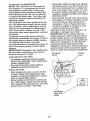
TROUBLESHOOTING
CHART
CORRECTION
PROBLEM
Wil! not start
o Out of fuel.
o Engine not "CHOKED"
properly.
Engine flooded.
• Bad spark plug,
o Dirty air filter.
Dirty fuel filter.
Water in fuel.
Loose or damaged wiring.
Carburetor out of adjustment,
Engine valves out of
adjustment.
Hard to start
Dirty air filter.
Bad spark plug,
Weak or dead battery.
* Dirty fuel fitter.
Stale or dirty fuel.
Loose or damaged wiring.
Carburetor out of adjustment.
Engine valves out of
adjustment.
Engine will not turn
over
o Clutch/brake pedal not
depressed.
Attachment clutch is
engaged.
Weak or dead battery,
Blown fuse,
Corroded battery terminals.
Loose or damaged wiring.
o Fau_bt ignition switch.
Faulty sotenoid or starter.
FauJty operator presence
switch(es),
Engine c_icksbut
witl not start
Weak or dead battery.
o Corroded battery termi_
nals,
28
Fill fuel tank.
o See "TO START ENGINE* in
Operation section.
Wait several minutes before
attempting to start.
• Replace spark plug.
o Clean/replace air filter.
Replace feel filter.
o Drain fuel tank and carburetor, refill tank with fresh
gasoline and replace fuel filter.
, Check att wiring.
- See "To Adjust Carburetor"
in Service and Adjustments
section.
• Contact an authorized service center,
Clean/replace air filter.
Replace spark plug.
Recharge or replace battePt,
Replace fuel filter.
Drain fuel tank and refill with
fresh gasoline.
Check all wiring.
See "To Adjust Carburetor"
in Service and Adjustments
section.
Contact an authorized service center.
Depress clutch/brake pedal.
Disengage attachment
clutch.
Recharge or replace battery.
Replace fuse.
Clean battery terminals.
Check all wiring.
CheckirepJace ignition
switch.
Check/replace solenoid or
starter.
Contact an authorized service center.
o Recharge or repiace battery.
Clean battery terminals.
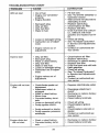
CORRECTION
Engine clicks but
will not start
- Loose or damaged wiring.
Fau_, solenoid or starter.
, Check all wiring.
,_ Check/replace solenoid or
starter.
Cutting too much
grass/too fast.
o Throttle in "CHOKE" position,
* Build-up of grass, I_aves
and trash under mower.
, Dirty air filter.
= Low oil level/dirty oil.
Faulty spark p|ug.
Set in "Higher Cut" position/reduce speed.
Adjust throttle control
(conrd)
of power
- Dirty fuel filter.
, Stale or dirty fuel.
,, Water in fuel
= Spark plug wire loose.
* Dirty engine air
screen/fins.
o Dirty/clogged muffter.
,, Loose or damaged wiring.
- Carburetor out of adjustment.
= Engine valves out of
adjustment.
Engine continues to
run when operator leaves seat
_th attachment
clutch engaged
-uneven
Clean unde_ide of mower
housing.
• Clean/replace air filter.
= Check pit levelJchange oil,
Clean and regap or change
spark plug.
, Replace fuel filter.
- Drain _uel tank and refill with
fresh gasoline.
,, Drain rue! tank and carburetor, refill tank with fresh gasoline and replace fuel filter.
• Connect and tighten spark
plug wire.
,, Clean engine air screen!fins.
Clean/replace muffler.
Check all widng.
- See "To Adjust Carburetor" in
Service and Adjustments
section.
Contact an authorized service center.
,, Worn, bent or loose blade.
,, Bent blade mandrel.
. Loose/damaged part(s).
Replace blade. Tighten blade
bolt.
, Replace blade mandrel.
T'_jhten loose part(s).
Replace damaged parts.
- Faulty operator-safety
presence controt system.
• Check wiring, switches and
connections, if not
corrected, contact an authorized service center.
-
o Replace blade. Tighten blade
bolt.
Level mower deck.
• Clean underside of mower
housing.
- Replace blade mandrel.
C|ean around mandrels _o
open vent holes.
Worn, bent or loose blade.
, Mower deck not level,
Buildup of grass, _eav_s,
and trash under mower.
,, Bent blade mandrel.
, Clogged mower deck vent
hoies from buildup of
29
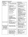
TROUBLESHOOTING
PROBLEM
Poor cut - uneven
(cont'd)
Mower blades will
not rotate
Poor grass discharge
CHART
FcAusE
CORRECTION
grass, leaves, and trash
around mandrels.
Obstruction
inclutch
mechanism.
Worn!damaged mower
drive belt.
Frozen idler pulley.
- Frozen blade mandrel.
Engine speed too slow.
o Travel speed too fast.
= Wet grass.
Mower deck not level.
Lowtuneven tire air pressure.
= Worn, bent or loose blade.
- Buildup of grass, leaves
and trash under mower.
Mower drive belt worn.
* Blades improperly
installed.
, Improper blades used.
Clogged mower deck vent
holes from buitdup of
grass, leaves, and trash
around mandrels.
o Remove obstruction.
Replace mower ddve belt.
• Replace idler pulley.
Replace blade mandrel.
® Place throttle control in
"FAST _position,
Shift to slower speed.
Allow grass to dry before
mowing.
Level mower deck.
Check tires for proper air
pressure,
• Replace/sharpen blade.
Tighten blade boll
• Clean underside of mower
housing.
= Replace mower drive belt.
• Reinstall blades sharp edge
down.
- Replace with blades listed in
this manual.
o Clean around mandrels to
open vent holes.
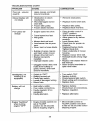
Headlight(s) not
working (if so
equipped)
o Switch is "OFF".
- Bulb(s) burned out.
,, Faulty light switch.
Loose or damaged wiring.
, Blown fuse.
Turn switch "ON".
o Replace bulb(s).
* Check!replace light switch.
Check widng and connections.
, Replace tuse.
Battery wil! not
charge
• Bad battery cell(s).
o Replace battery.
Check/clean a!I connections.
Replace regulator.
Faulty regulator (if so
equipped).
- Faulty alternator.
Engine "backfires"
when turning
engine "OFF
o Engine throttle control not
set at "SLOW"
position for 30 seconds
before stopping engine.
3O
o Replace alternator.
* Move throttle control to
"SLOW" position and allow
to idle for 30 seconds before
stopping engine.
31
32
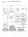
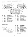
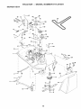
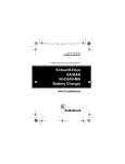
TRACTOR
- - MODEL NUMBER 917.270311
SCHEMATIC
BAT'FERY
AMMETER
(OPTIONAL)
IGN|TION
SWITCH
HEADUGHTS
"MAKE"
I RUWUGHT_
B+L
L R,_ I B÷L
A+¥
.o.E
NOTE
YOUR TRACTOR I8
EQUIPPED WITH A SPECIAL
ALTERNATOR SYSTEM,
THE LIGHTS ARE: NOT
CONNECTED TO THE
NON-REMOVABLE
REMOVABLE
/-7L7
BATTERY, BUT HAVE THEIR
CONNECTIONS
CONNECTIONS
OWN ELECTRICAL SOURCE,
BECAUSE OF THIS, THE
W_RiNG INSULATED CLIPS
BRIGHTNESS OF THE LIGHTS
WiLL CHANGE WITH ENGINE
NOT_: IF WIRING INSULATED
SPEED, AT IDLE THE LIGHTS
CLIPS WERE REMOVED FOR
WILL DiM, AS THE ENGINE IS
SERVICING OF UNIT, THEY
SPEEDED UP, THE LIGHTS
SHOULD BE REPLACED TO
WILL BECOME THEIR BR;GHTEST,
PROPERLY SECURE YOUR WIRING°
33
TRACTOR
o o MODEL
NUMBER
ELECTRICAL
34
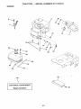
917o270311
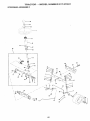
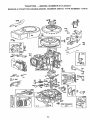
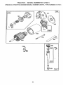
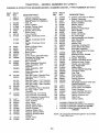
TRACTOR o o MODEL NUMBER 917o270311
ELECTRICAL
KEY
PART
NO°
NOo
1
2
3
4
6
8
t6
19
20
2t
DESCRIPTION
24
25
26
144925
74760412
STD55t025
STD551125
STD54t025
158417
153664
STD551125
73350400
136850
4!52J
4799J
146147
t08824X
Battery 12 Volt 25 AMP
Bolt He× Hd t/4-20unc X 3/4
Washer 9/32 X 5/8 X 16 Ga
Washer Lock t-ivy Hetical I/4
Nut Fin He){ 1/4-20 Unc
Case Battery
Switch Inter_ock Push-in
Washer Lock 1/4
Nut Jam Hex 1/4-20 Uric
Harness Socket Light W/4152J
Bu!b Light #11.58
Cable Battery 6ga tl" red
Cable Battery 6 Ga W/t6 Wit red
Fuse 30 AMP Auto Green
28
29
30
31
32
33
40
4t
42
43
44
48
52
70
4207J
121305X
140301
12421tX
141226
t09310X
158442
71110408
131583
145873
73640400
140844
141940
140413
Cable Ground 6ga 12" b_ack
Switch Plunger Nc Gray
Switch Ign 4 pos
Nut Ignitk)n
Cover Sw Igni_on
Key kjn Molded Craftsman, DeJta
Harness Man CfAm Hm 97
BaR Blk Hex 1/4-20uns x t/2
Cover Terrnlna! Red
Solenoid
Nut Keps BIk Hex !/4-20 Unc
Adapter
Protection Wire Loop
Harness Engine, Dual 14 OHV
NOTE:
Alt component dimensions give in U.S. inches
1 inch = 25A mm
35
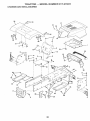
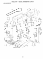
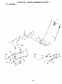
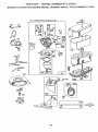
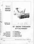
TRACTGR =oMODEL NUMBER 91 ?'.27G3!1
CHASSIS AND ENCLOSURES
30
17
21
33
10
,<<L
36
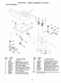
TRACTOR
- =MODEL NUMBER 917o270311
CHASSIS AND ENCLOSURES
KEY
PART
NO.
NOo
1
2
3
4
5
6
7
8
9
t0
11
13
14
15
16
17
18
19
21
22
24
25
26
28
29
30
31
33
34
35
37
38
39
54
140
145
181
- -
NOTE:
160393
140356
17490612
STD551025
155272
155924X014
126842x
155138
1619t3X012
STD533710
155927
t55934)(010
17490608
74180512
STD54143t
154988)(558
126938X
17521312
I22933X
124479)(
STD523710
19131312
STD54t437
140137
124029)(
157584X558
136619
t05476)(558
I05475X558
STD533707
17490508
139886
139887
161464
158418
158524
161547
5479J
DESCRmPT_ON
Chassis
Drawbar Stretch
Screw Thdrol 3/8-16x3/4 Ty-tt
Washer 13/32 x 3/4 × t6 Ga.
Bumper Hoed!Desh
Saddle Slksc Flat LT 5Sp Dana
Heat Shietd Sloped Hoed
Clip Retainer Slide On
Dash Silkscmened
Bolt Rdhd Sqnk 3/8-16 Unc x 1
Panel Pnt Dash Lh
Panel Slkscr Dash Rh Weldment
Screw Thdrol 3/8-16xi/2 Ty_tt
Screw Mach T_d 5/16-18uncx3/4
Nut Keps 5/t6-18 Unc
Hood Asm Pnt
Bumper Hood
Screw Sltd Hex Hd wiPI Washer
Rivet Ratchet Nylon
Washer Nylon Blk 28x 75x t9
Bolt Fin Hex 3/8-16uric X t
Washer13/t6X13/16X
12Ga
Nut Lock 3/8-16 Unc
Gdlle Black
Lens Headlight Bar Clear
Fender Pnt
Bracket Pnt Fender
Footrest Pnt Lh Pe,ff
Footrest Pnt Rh Peff
Bolt Rdhd Sht Sqnk 3/8-16 X3/4
Screw Thrdrol 5/16-18 × 1/2 Tyt
Bracket Asm. Pivot, L.H. Mower Rear
BracketAsm. Pivot, R.H., Mower Rear
Screw He× Wshd 8-18 x 7/8
Bracket Suspension Front
Red Pivot Chassis/Hood
Extrusion. Hood
Plug Button Blk 359 Die
Alt component dimensions give in UoS. inches
1 inch = 25.4 mm
37
GROUND DRIVE
TRACTOR _- MODEL NUMBER 917o270311
37
26
27
38
TRACTOR
o - MODEL NUMBER 917.270311
GROUND DRIVE
KEY
NO.
t
PART
NO.
.......
2
3
4
5
6
7
8
10
11
t2
13
14
15
18
146682
123868X
12000028
12!520X
17490512
162240
! 3t 679
STD5612t0
105701X
19151216
74550412
STD551125
74490544
STD523710
t9
21
22
24
25
26
27
28
29
30
31
32
24
35
36
37
38
STD541437
1045933X
130804
STD541237
t 06888X
STD551037
STD561210
145204
124236X
130807
t27275X
STD523107
155071
I20183X
STD551082
STD571810
123674X
39
STD523727
DESCRmPTJON
KEY
NO,
PART
NOo
40
41
42
47
48
49
50
51
52
53
55
56
57
58
59
6i
62
63
84
65
68
70
72
74
75
76
77
78
!12
!!6
148
149
t50
151
4470J
154777
19131312
127783
154407
123205X
STD5237t5
STD541437
STD541431
105710X
105709X
STD523712
160855
127274X
1403I 2
17490612
8883R
140186
71170764
8TD55t143
t54778
t 34683
19132012
t09502X
12t749X
STD581075
123583X
121748X
190912t0
72110610
159103
122052X
150935
19133210
Transa×te (See Breakdown)
Dana 4360420
Spdng Return Brake T/a Zinc
Pulley Transaxle Alum
Ring Retainer # 5100-62
Strap Pnt Torque 30 Deg 81k
Screw Thdrot 5/t6-!8 X 3/4 Tyl
Bracket T/a Saddle Shift
Rod Shifter BIk
Pin Cotter t/8 X 1 Cad
Washer Plate Shf 388 8q Hole
Washer t5/32 X 3/4 X 16ga
Bolt 1/4-28unf Gr8 w/Patch
Washer Lock Hvy Helical 1/4
Bolt Hex FLGHD 5/t 6-18 Gr.5
Bolt Fin Hex 3/8-16 Uric x I Gr,
5
Nut Lock 3/8-16 Unc
Knob Rd 112-13 Plstc Thds Btk
Rod Brake Lt
Nut Hex Jam 3/8-16 Unc
Spdng Rod Brake 2 O0 Zinc
Washer 13/32 X 13/18 X t6 Ga
Pin Cotter t/8 X 3/4 Cad
Rod Brake Faridng Lt/Yt
Cap Parking Brake Red
Bracket Transmission
Keeper Belt Lh Lt 14 Ga
Bolt Fin He× 5/t6-t8 × 3/4
Shaft Asm Pedal Foot
Beadng Nylon Blk 629 ld
Washer 21/32 X 1 X t6 Ga
Pin Ro]J 3/t6 X 1"
Putley ldler Flat
Bolt Fin Hex 3/8-t6uoc
X 2-3/4
NOTE:
39
DESCRIPT}ON
Spacer Split 395 X 59 Bzp
Keeper Belt tdter Fool Proof
Washer 13132 X 13/t6 X t2 Ga
Pulley idler V Groove Plastic
8eltcrank Ct_ch Grad Dry Stl
Retainer Belt Style Spring
Bolt Hex Hd 3/8-16unc X 1-t/2
Nut Crownlook 318-18 Unc
Nut Lock 5/16-t8 Uric
Link Clutch 7 66
Spring Return Clutch 6 75
Bolt Fin Hex 318-t6uoc X t-1/4
V-belt Ground Drive 95.30
Keeper Belt Rh Lt PntJzinct6g
Retainer Belt Chassis Lh Zinc
Screw Thd,-'of 3/8-t 6x314 Ty4t
Cover Pedal Bfk Sl;d
Pulley Engine
BOlt Finhex 7!16-20 × 4 g5
Washer Lock Hvy Hlcl Spr 7/16
Keeper Belt Engine Fool Proof
Guide Belt Dr Mower Rh
Washer 13132 X 1-1/4 X 12 Ga
Spacer Split
Washer 25/32 X 1 114 X 18 Ga
Fling E #5133-75
Key Square 2 0 X 18451 1865
Washer 25/32 X 1 5/8 X 16ga
Waet_r 9/32 X 3/4 X 10 Ga
Bolt Rdt,4 Sqnk 3/8-16 x !.25
Spacer
Spacer Retainer Pm Mower
Bushing Nylon Cotlered
Washer 13/32 x 2 x t0 Ga
All component dimensions give in U.S.
inches 1 inch = 25.4 mm
TRACTOR
== MODEL NUMBER 917.270311
STEERING ASSEMBLY
40
TRACTOR
STEERING ASSEMBLY
KEY
NO.
PART
NO.
2
3
4
5
8
7
8
9
10
tt
t3
15
t7
t8
19
20
22
23
25
26
27
28
29
30
3;2
36
37
38
39
40
4t
42
43
48
47
62
85
86
67
88
t 39768
154427
t58483
157473
6266H
121748X
19272016
12000029
33r_R
158438
STD55t137
154779
73901000
158545
57079
t 24035X
126no84X
7 !200410
127501
154406
128847X
138874
19131416
17490612
STD581210
130465
168099
152927
139769
19133808
STD541537
t04820X
t244!7X
12t749X
121232X
6855M
t56593
t 54780
154404
74781044
154429
NOTE:
o ° MODEL NUMBER 917.27031t
DESCRtP'RON
Steedng Whee!
Axle Assembly STMP D_opped STL
Spindle Assembly, L.H.
Spindle Assembly, R.H.
Beadng, Race, Thrust, Hardened
Washer 25/32 x 1-5/8 x 16 Gauge
Washer 27/32 x 1-1/4 × 16 Gauge
Ring, Klip
tSeadng, Steering Column
Draglink Extended Stamped
Washer, Lock
Beadng Axle STLT/GT
Nut, Lock, Flange 5/8-tl UNC
Shaft Assembly, Steering
Washer, Thrust .515 x .750 x.033
Support, Shaft
Washer, Shim !/4 x 5/8 x .062
Screw, Hex Socket 1/4-20 x 518
Pittman Shaft Assembly
Bracket, Steering
IBushtng, Link, Drag
Gear, Sector
Washer 13/32 x 7/8 x 16 Gauge
Screw, Thd., Roll 3/8-_6 x 3/4
Pin
Rod, "13e
Bushing, Steedng
,_ew
Cap, Steering Wheel
Washer 13f32 x 2-3/8 × 8 Gauge
Gripco Nut
Adaptor, Steering Wheet
Boot, Steering Shaft
Washer 25/32 × 1-t/4 x 16 Gauge
Cap, Spindle
Fitting, Grease
Kit Steering Asm Service
Spacer Axle
Bearing Arm Pittman
tE_lolt,
Fin Hex 5/8-11 UNC x 2-3/4
Axle, Brac_
AIt comI_nent dimensions given in U.S. inches
t inch = 25.4 mm
4t
TRACTOR
° _ _'IODEL NUMBER 917.27031!
ENGINE
78_
38
37
33
23
29
/
\
OPTIONAL _QU_P_NT
42
TRACTOR ° - MODEL NUMBER 9t7=27031!
ENGINE
KEY
NO.
1
2
3
4
t3
14
15
t6
23
29
31
32
33
35
37
38
40
44
46
62
72
7B
81
PART
NO,
162144
17720410
.......
137348
272293
13280324
13200300
STD55t237
159880
137180
I09202X
158990
t23487X
17490512
137040
......
124028)(
17490412
19091418
STD55113t
71070512
17490620
128861
DESCR{PT_Ohi
Control Th/Ch Rh elk Pdl
Screw Hex Thd Cut 114_20x5/8 T
Engine (See Breakdown) B&S
Model No. 289707-II79-E1
Muffler Exhaust B&S Lt
Gasket t 313 td Tin Plated
Nipple Pipe 3/8 Npt X 3"
Elbow Std 90 Degree 3/8-t8 Npt
VVasher Lock Ext Tooth 3/8
Shield Bn_Dbr Guard
Arrestor Spark
Tank Fuel t 25 Fr
Cap Asm Fuel Vented Sears
Clamp Hose Btk
ScrewThdrct 5/16-18 × 3/4
Line Fuel 20"
Plug Oil Drain (Order From Engine Manufacturer)
Bushing Snap Ny_ Blk Fuel Line
Screw Hexwsh Thdro1114-20x3/4
Washer 9/32 X 7/8 X tTga
Washer Lock Hvy HIOtSpr 5/t6
Screw Hex.hd Cap 5/t6_18:,_'4
Screw ThdroI 3/8-18x1-1/4 Tytt
Nut Flange I/4-L:_0 StarterNut
NOTE: All component dimensions given in U.S. inches
t inch = 25.4 mm
43
TRACTOR -o MODEL NUMBER 917o2703tt
SEAT ASSEMBLY
\
KEY
NO.
I
2
3
4
5
6
7
8
£
lO
11
12
PART
NO.
KEY
NO.
DESCRtPTaON
PART
NO.
151205
1443551
STD5237t0
19131610
Seat V3_
Bracket Pnt Pivo_ Seat (bfk)
8oft Fin Hex 3/8-t6unc X t
Washert3!32X3/4X10Ga
13
t4
15
t6
121248X
72050412
134300
t21250X
145006
ST054t437
Clip Push In Hinged
N_ Crownlock 3/8-16 Unc
!7
21
t23976X
1532_
12418tX
17490816
t9!316!4
155925
120088X
Spring Seat Cprsn 2 250 elk Zi
Screw Tt_drol 3!8ot6 X t Ty41
Washer 13/32 X t X 14 Ge
Pan Pnt Seat (blk)
KBob Seat I/2-t3 Unc elk
22
24
25
STD54143t
19171912
1270!8X
121246X
Bracket Pnt Mounting Switch
NOT_:
44
DESCRiPTiON
Bushing Snap elk Nyt 50 td
Bolt Rdbxl Sht Nk t/4-20x1-1/2
Spacer Spli_ 28 X 98 Zinc
Spdng Cprsn 1 27 _fk Pnt
Nu_ Lock t/4 Lge Rg Gr 5 Zir_
8o1_ Shoulder 5/t6-I8 Unc 81kz
Nut Crown Lock 5116--18
Washer 17132 X 1-3/1_ X t2 Ga
Ebit Shoulder 5/1_ot8 X 62
All component dimensions
t inch = 25,4 mm
given in U,S, inches
TRACTOR o - MODEL NUMBER 917o270311
DECALS
t5
KEY
NO.
PART
NO.
156867
272936
3
4
6
16399O
163991
133644
8
9
10
1t
12
163247
1632O4
149516
156439
4900J
KEY
NO.
DESCRIPTION
Decal
Decal
Crafts
Decal
Decal
Decaf
Dora
Decal
Decal
Decal
Decal
Decal
PART
NO,
Oper Sdl P/L Eng
Engine 12.5 Hp B&S iC
13
15
t 46046
136832
Hood Slope Rh
Hood Slope Lh
Maint Customer Sears
t8
"t9
21
----
133179
183992
t 3t 265
138311
t64876
164877
Panel Dash
Fender Craftsman
BtP/Dngr/Ps_ Eng. Acme
Fender Danger
Clutch/brake English
DESCRIPTION
Decal V-belt Dr Sch Tractor
Decal Mower Drive Schematic
38
Decal Mower Qc System
Decal Fender Sd
Decal Lfghtbox
Decal Lift Handle
Manual, Owner's (English)
Manuai, Owners (Spanish)
WHEELS & TIRES
KEY
NO.
1
2
3
4
5
6
7
8
9
!0
11
5,8
PART
NO.
DESCRgPT_ON
59t 92
65139
t24157X
59904
t06732)(427
Cap Value Tim
Stem Va_ue
Tire F t5 X 6 0 - 6 Serv_ce
Tube Inner Front #35060
Rim Asm 6"front White SeP_ice
276H
9040H
106t 08>(427
t23969X
7152J
104757X
144334
F_ng Grease
Bearing Flange
Rim Asm 8"rear White Service
Tire R t8x8 5,.B
Service
Tube Rear9 5 X 8 Service
Cap Axfe Btk t 50 X t 00
Sealant, Tire (10 oz. Tube)
NOTE: All component dimensions
1 inch = 25.4 mm
45
given in U.S, inches
TRACTOR =- MODEL NUMBER 917o270311
LiFT ASSEMBLY
13
13
_o
32
46
_ _'_ ,o_,_.
_.
TRACTOR o o MODEL NUMBER 917.270311
UFT ASSEMBLY
KEY
NO,
PART
NO,
t
2
3
159460
159474
t05767X
Wire Asm innedSprg w/plunger tT
Shaft Asm. Lift
Pin Groove
12000002
19211621
120183X
!25631X
t22365X
139865
139866
STD624008
127218
73350800
130t 71
73300800
t 39868
8TD624008
140302
73540600
IE Ring #5133-62
Washer 21/32 x 1 × 2t Ga.
Bearing Ny_ong
Grip Handle Fluted
Button Plunger Read
Lift Asm. Link LH
Lift Asm. Unk RH
Retainer Spring
Link Front
Nut Jam Hex t/2-13 Uric
TnJnn_on BIk Zinc
Nut Lock W/Wsh 1/2-t 3 Uric
Arm Suspension Mower
Retainer Spring
Beanng, Pvt. Lift, Sphert¢_
Nut Crowntock 3/8-24
4
5
6
7
8
1t
12
13
!5
16
17
18
t9
20
31
32
NOTE:
DESCRIPTION
All component dimensions given in U.S, inches
t {rich = 25.4 mm
47
TRACTOR
o=MODEL NUMBER 917o270311
MOWER DECK
73
21_
\
2
48
88
TRACTOR ooMODEL NUMBER 917o270311
MOWER DECK
KEY
NO.
PART
NO_
1
2
3
142829
STD533107
138017
4
138440
5
6
8
STD624008
130832
850857
9
STD551t37
KEY
NO.
DF-SCRIPTJON
PART
NO.
Mower Housing Assembly
Bolt, Carriage 5/t8_18 x 3/4
Bracket Asm. Fram Sway Bar
38/42
Bracket, Asm, Deck Sway Bar
38"
Retainer, Spring
Asm. Suspension Rear
8oil, Hex 3/8-24 x 1-1/4 Grade
8
55
56
67
68
69
71
72
73
74
t 33840
122052X
162113
144200
STD560907
142427
131870
127847
t21748X
Washer, Lock, Hvy Hlcl Spring
3/8
Washer, Hard 8tade Mower
Vented
75
76
77
12000029
128903
127845
78
79
80
8I
82
86
160571
127498
153701
STD541237
142028
7631J
87
88
128772
19111216
89
92
19131612
STD541437
10
140296
11
12
!3
134148
129995
!3764.5
14
15
128774
110485X
Blade, Mower, Mutching 38"
Ball Bearing
Shaft and Bearing AssembIy
(includes Key Number 15)
Mandrel Housing, Vented
Ball Bearing, Mandrel
t6
t9
140329
132827
Stripper, Mower, Vented
Bolt, Shoulder
2t
23
24
25
26
27
28
STD541431
137607
105304X
t237t3X
1t0452X
t06735X
19111016
29
30
31
32
33
38
40
4t
43
45
108735X
157722
129963
153532
137269
131494
STD541437
133551
133504
STD624003
Nut, Crownlock 5/t6-18
Bracket, Mower Deflector
Cap, Sleeve
Spring, Deitector
Nut, Push
Shieid, Deflector
Washer tt732 x 3/4 x t6
Gauge
Rod, Hinge
Screw. Tndrot Washer Hd
Washer, Spacer
Pulley, Mandret
Nut, Flangelock 9/16
Pulley, Idler, Flat
Nut, Crownlock 3/8-t6
Rod, Pivot
Rod, Clutch, Secondary
Retainer, Spring
53
54
130840
133943
Brake Assembly
Washer Hardened
107
108
109
tt0
113
133502
133503
74760640
142587
17490512
122
123
124
128
141
--
131289
131288
STD533717
153390
6268H
130794
-NOTE:
49
142820
DESCR!_PTJON
Idler Arm Assembly
Spacer, Retainer 1-3/4
Knob
Belt
Pin, Cotter 3/32 × 3/4
Rod, Clutch, Primary
Spring, Return
Arm, Clutch, Secondary
Washer 25?32 x t-5/8 x 16
Gauge
Ring, Kltp
Bolt, Shoulder
Keeper, Spdng
Arm, Clutch, Pdmary
Bushing
Spring
Nut Hex Jam 3/8-16 UNC
TnJnnion Adj 94
Runner, LH
Runner, RH
Washer 11?32×3/4x 16
Gauge
Washer 13/32 x 1 x 12 Gauge
Nut Lock Hex w/Ins 3/8-16
UNC
Spacer, Retainer
S_iffener, tdter Arm
Boit, Flex Head 3/8-t8x2-t/2
Upstop Deck Front 38=
Screw, Hax Head, Thd., Roll.
511648 x 3/4
Rod, Brake, LH
Rod, Brake, RH
8clt, Carriage 3/8÷16 x t-3/4
Washer Felt
washer ThnJst .75 x t ,230
Mandrel Assembly (includes
Key Numbers 12-15, t7-19, 31
and 33)
Mower Deck, Complete
All component dimensions
t inch = 25,4 mm
given in U,S.inches
TRACTOR
- o MODEL NUMBER 917.270311
DAHA TRANSAXLE - o MGDEL NUMBER 4360o120
22
53
57
!9
43_
//
52
?0
5O
TRACTOR _ o MODEL NUMBER 917.27'03!1
DANA TRANSAXLE
KEY
NO.
PART
NO.
t
2
3
4
5
160939
2274J
134400
105904X
160940
6
7
8
9
10
11
12
_3
138235
t08727X
148268
148289
2225J
134793
148268
1204t5X
14
15
t6
17
t8
19
20
21
22
23
24
25
26
27
28
29
30
3t
32
33
34
35
142674
161563
161564
105909X
105910X
160942
160943
148267
138236
73810500
142676
2244J
105916)<
t 20470)(
t10070X
142677
t24644X
108980)(
t29406X
t 34796
t 3,$797
105925X
36
2228J
o ° MODEL NUMBER 4360-120
KEY
NO.
DESCRIPTYON
PART
NO.
Housing, Upper
Screw, Tapping, 1/4_20 X .734
BarI, Detent
37
223tj
38
160944
Spring, Detent
Screw, Tapping, No.t0-24 X
.482
A_sy, Shifter
V-Ring
Bearing, Flange
Seal, Oil
Ring, Retaining
Aeay, Kit, Shim, .625 Shaft
E_adng, Flange
Washer, Plain, .632 × 1.38 X
,046
Key, Woodruff, No. 9
Aeay, Kit, Input Shaft
Pinion, Bevei, t2T
Ring, Retaining
Chain, 24 P_ohes
Cover, Detent
Gear, Spur, 12T
Collar, Ciutch
Assy, Kit, Clutch Keys
Nut, Lock, 5/16-24
Shaft, Intermediate
Key, Woodruff, No. 61
Ring, Retaining
Sprocket, t8T
Spacer, t.131 X t.45 X .494
Gear, Spur, 37T
Gear, Spur, 30T
Gear, Spur, 25T
Gear, Spur, 22T
Gear, Spur, !9T
Spacer, 1.133 X 1.50 X .375
Washer, P_aJn, .640 X 1.37 X
.061
39
40
41
42
43
44
45
46
47
48
49
50
5t
124639X
120472X
t05928X
161565
134394
120473X
142678
I24641X
t06589X
120_08X
t05937×
105938X
222&J
52
53
"f34401
2264J
54
55
56
57
58
59
60
61
62
63
64
65
68
67
68
69
160946
160947
160948
110071X
120952X
160949
160950
142680
12096tX
7294J
108989X
t6095;2
120954X
160953
138244
108998X
70
160954
Washer, Plain, .632 X 1.00 X
.046
71
72
t2095tX
120416×
DESCRPT_ON
Washer, Plain, .632 X t.00 X
.031
Assy, Gear, Comb., 12T & 30T
Shaft, idler
Spacer, .633 X .87 X .755
Sprocket, 9T
Gear, _vel, 38T
* Assy, Kit, Shim, ,750 Shaft
Shaft, Drive
Gear, Spur, 121
Gear, Spur, 20T
Gear, Spur, 25T
Gear, Spur, 28T
Gear, Spur, 3tT
Spacer, .781 x 1.00 x .375
Washer, Plain, .632 X 1.00 X
,OK)
Washer, Neoprene
Washer, Plain, .758X 1.25X
.031
Axle, LH
Gear, Miter, 12T
Ring, Retaining
Gear, Spur, 32T
Shaft, Cross
Gear, Miter, 12T
Axle, RH
Housing, Lower
Puck, Friction
Disc, Brake
Spacer, Brake Puck
Jaw, Brake
Pin, Dowel
Screw, Tapping, 5/t6-18 × 2.35
Lever, Actuating
Washer, Plain, .32t X 1.00 X
.055
Bracket, Anti-Potation
Pu_., Friction
Grease
NOTE: All component dimensions given in U.S. inches
1 inch = 25.4 mm
51
_2
965
53
%
123
_0 I044
53
523
284
_524
54
TRACTOR
° ° MODEL NUMBER 9t7.2703!1
BR_GGS& STRATTON ENGINEoMODELNUMBER 289707, _PE NUMBER 0179-E1
PART
NO.
KEY
NO.
1
2
496413
399265
3
5
7
8
9
10
11
12
391086
494240
271866
495735
27803
94621
280100
271916
271997
271996
t3
!5
16
t8
20
22
23
94622
94239
498971
494238
291675
94624
492326
24
25
222698
394661
394682
394663
Cylinder Assembly
Bearing, Cylinder (Requires
Spedat Toots For Installation)
" Seal, Oil
Head, Cylinder
_ Gasket, Cylinder Head
BreatherAssernbly
z_ Gasket, Valve Cover
Screw, Seres
Tube, Breather
* Gasket, Crankcase Cover
1/64"
* Gasket, Crankcase Cover
.005"
* Gasket, Crankcase Cover
"009°
Screw, Cylinder Head
Plug, Oil Drain
Crankshaft
Base, Engine
° Seal, Oil
Screw, Sems, Base Mounting
Flywheel and Ring Gear
Assembly, Magneto
Key, Flywheel
Piston Assembly, Standard
Piston Assembly .010"
Oversize
29
490348
490469
32
33
34
94671
262246
262247
Piston Assembly .020"
Oversize
Piston Assembly .030"
Oversize
Ring Set, Piston, Standard Size
Ring Set, Piston, Chrome,
Standard
R_ng Set, Piston .010" Oversize
Ring Set, Piston .020" Oversize
Ring Set, Piston .O3O"Oversize
Lock, Piston Pin
Pin Assembly, Piston, Standard
Pin Assy, Piston .005"
Oversize
Rod Assembly, Connecting
Rod Assembly, Connecting,
.020 _ Undersize Cr_n_qoin Bore
Screw, Connecting Rod
Valve, Exhaust
Valve, Intake
35
36
37
40
41
65906
26828
224502
221598
292260
Spring, Intake Valve
Spring, Exhaust Valve
Guard, Flywheel
Retainer, intake Valve
Rotocoif, Exhaust Valve
42
494553
45
46
262246
212897
Retainer, Exhaust Valve
Rotecoif
Tappet, Valve
Gear, Cam
394664
26
27
28
391780
392331
391781
391782
391783
2_3t29
2£9691
391286
PART
NO.
KEY
NO.
OE$CR_PT_ON
DESCRiPTiON
51
52
53
73
75
78
93
94
95
98
!04
t05
t06
108
110
!21
123
125
127
t30
131
133
137
138
14t
142
272465
272554
94637
224517
224061
94626
281346
498030
94098
495800
231789
231855
231854
224540
225137
499220
94913
498027
-*224539
494379
494381
281165
281164
495931
497568
_, Gasket, Carburetor [to Elbow)
Z_ Gasket, Carburetor
Stud, Carburetor Mounting
Screen, Rotating
Washer, Spring
Screw, Sems
Bushing, Throttle Shaft
Valve, Needle
_ Screw, Throttle
Screw, ldte Speed
_ Pin, Float Hinge
, Valve Assembly, Inlet Needle
Inlet, Vaive Seat
Valve, Choke
Washer, Flat
Carburetor Overhaul }{.it
Screw, Elbow Mounting
CarburetorAssernbly
Plug, Welch (Sold in Kit Only)
VaNe, Throttle
Shaft and Lever, Throttle
Float, Carburetor
0_ Gasket, Float Bowl
_, Washer, Float Bowl Screw
Shaft and Lever, Choke
• Nozzle / Jet, Carburetor
146
94198
Key, Timing Gear
164
t71
186
t87
188
20t
209
218
219
213819
281051
493496
296004
94827
262767
260871
262768
490815
222
224
225
227
230
232
240
265
495611
94513
495157
493935
94927
262785
394358
221535
Intake, Elbow
Nut, Air Cleaner Mounting
Connector, Hose
Line, Fuel
Screw, Seres
Unk, Govemo_
Spdng, Governor
Link, Choke
Oil Slinger, Govemor Gear and
Bracket Assembly
Plate, Governor Controi
Screw, Seres, Air Cteaner
Crank, Governor
LeverAssembty, Governor
Washer, Governor Crank
Spdng, Governor Link
Fi_ter, Fuet
Clamp, Casing
"
tnctuded in Gasket Set (494241)
_
0
z_
tnc_uded in Carburetor Overhaul Kit (499220)
Included in Cadouretor Gasket Set (494385)
Included in Valve Overhaul Gasket Set
(498539)
NOTE: All component dimensions
t inch = 25,4 mm
55
given in U.S. inches
KEY
NO=
PART
NO.
284
94903
284A
3O4
305
94704
498282
94788
306
307
224545
94980
308
309
310
311
333
334
491490
497595
94003
497608
492341
94731
337
348
356
358
383
383
445
455
467
474
482
5O3
5t0
523
524
525
535
537
544
552
562
592
582A
601
611
614
615
618
634
634A
635
648
657
68.3
668
725
802592
94898
494328
494241
19203
89838
498984
222561
493903
393474
93621
808000
497606
495230
26 t 370
496113
272403
261106
497803
491986
94907
231978
92278
93053
493496
93306
263080
262803
484455
491323
66538
224546
94906
94929
280648
392134
727
490324
728
729
729A
741
94951
281159
225170
262932
KEY
DESCR_PTION
NO.
Screw, Shoulder,
Hex Washer Head
Screw, Hex Head
Housing, Blower
Screw, Seres, 8lower Housing
Mounttr_g
Shield, Cylinder
Screw, Seres, Cylinder Shield
Mounting
Cover, Cylinder Head
Motor, Starter
8ott, ThnJ
8rush Set
Armature, Magneto
Screw, Seres, Armature
Mounting
Plug, Spark
Screw, Hex Head
Wire, Ground
Gasket Set
Pultar, Flywheel
Wrench, Spark Plug
Cartridge, Air Cleaner
Cup, Screen Mounting
Knob, Air Cteaner
Stator, Alternator
Screw, Seres
Strap, Starter
Drive, Starter
Cap and Dipstick, Oil Filler
Sea!, Filler Tube
757
758
759
781
783
801
802
803
842
847
851
889
8"10
87t
872
875
877
955
965
975
977
1005
1006
1036
1044
1090
t091
2500
----
Tube, Oil FilJer
Etement, Air Cleaner
PART
NO.
DESCRIPTION
213998
399891
230787
94593
280104
497626
497607
497604
270920
496415
493880
26t4&3
262924
28196_
231218
281104
494237
393456
94642
94010
495933
494385
280687
224413
499362
94673
497605
281384
288707-4528
498606
RPM Settings:
Unk, Counterweight
Counterweight Assembly
Pin, Counterweight
Screw, Counterweight
Gear, Starter
Cap, Odve
Cap, End
Housing, Starter
Seal, Oil Filler Cap
Fill Group, Oit
Terminal, Ignition Cable
Seat, _ntake Valve, Standard
Seat, Exhaust Valve, Standard
Guide, Exhaust Valve
Guide, Intake Valve
Cover, Air Cleaner
Body, Air Cleaner
Wire, Aitemator
Screw, Fue_Bowl
Locknut, Air Cleaner Mounting
Bow_ Assembly, Carburetor
Carburetor Gasket Kit
Fan, Ftywhee_
Retainer, Fan
Label, Kit - Emission
Screw, Hex Head
Retainer, Brush
Cap, Limiter
Replacement Engine
Replacement Shorib]ock
Low: I550-1950;
High: 3200-340_
O-Ring, Air Cteaner
Armature, Starter
"
#_cluded in Gasket Set (494241)
Bushing, Governor Crank
BOlt, Governor Lever
.
Included in Carburetor
Overhaut Kit (499220)
Nut, Hex
Nut, Hex
0
included in Carburetor
Gasket Set (494385)
Clamp. Fuel Pipe
Fuel _nlet Tube
Cotter, Pin
Retainer
A
Included in Valve Overhaul Gasket Set (498539)
NOTE: All component
Spring, Choke Return
Seaf, Choke Shaft
Sea£ Governor
Elbow, Spark Plug
Brace, Air Cleaner
Screw, Seres
Screw, Hex Head
Spacer
Gear, Ring
(Includes Mounting Parts)
Cover, Starter
(includes Mounting Screws)
Screw, Ton_
Clip, Lead Wire
Retainer Wire
Gear, "Rming
dimensions
! rich = 25.4 mm
56
given in U,S, inches
57
58
SUGGESTED
_o
GU}DE FOR SmGHTING SLOPES
FOR SAFE OPERATION
For the repair or replacement parts you need
deJivered direcUy to your home
Call 7 am - 7 pro, 7 days a week
t o800o368oPART
(1-800=366-7278)
Pare ordenar p_ezas con entrega a
do_¢iHe
_ t o800o659_7084
For in=house major brand repair service
Call 24 hours a day, 7 days a week
1o800o4oREPAaR
(1-800-473-7274)
Pare pedir eervi¢io de reparaciSn a
domicJlio _ 1o800o876o5811
For the location of a Sears Parts and
Repair Center in your area
Call 24 hours a day, 7 days a week
1..800=488o1222
For information on purchasing a Sears
Maintenance Agreement or to inquire
about an existing Agreement
Call 9 am - 5 prn, Monday-Saturday
i °800°827°6655
When requesting sen#ice or ordering
pa_s, always provide the fol!owing
information:
o Product Type
, Part Number
Mode0 Number , Pa_t Description
America's
164876
03oi9o98
Revo I
RD
Repair
Speciam._ts
Printed
in Uo_:_°A°