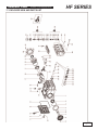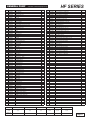
1
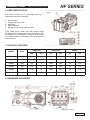
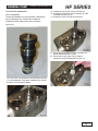
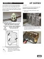
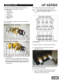
HF
Owner’s Manual
• Installation
• Use
• Maintenance
General Pump is a
member of the
Interpump Group
8
GENERAL PUMP
INDEX
A member of the Interpump Group
HF SERIES
1.
INTRODUCTION . . . . . . . . . . . . . . . . . . . . . . . . . . . . . . . . . . . . . . . . . . . . . . . . . .Page 3
3.
SAFETY . . . . . . . . . . . . . . . . . . . . . . . . . . . . . . . . . . . . . . . . . . . . . . . . . . . . . . . . .Page
3.1 General safety warnings . . . . . . . . . . . . . . . . . . . . . . . . . . . . . . . . . . . . . . . . . .Page
3.2 High pressure unit safety requirements . . . . . . . . . . . . . . . . . . . . . . . . . . . . . .Page
3.3 Safety of operation . . . . . . . . . . . . . . . . . . . . . . . . . . . . . . . . . . . . . . . . . . . . . .Page
3.4 General procedures for high pressure lance/gun operation . . . . . . . . . . . . . . .Page
3.5 Safety of maintenance . . . . . . . . . . . . . . . . . . . . . . . . . . . . . . . . . . . . . . . . . . .Page
2.
4.
5.
6.
7.
8.
9.
10.
11.
12.
SYMBOL DESCRIPTIONS . . . . . . . . . . . . . . . . . . . . . . . . . . . . . . . . . . . . . . . . . .Page 3
3
3
3
4
4
4
PUMP IDENTIFICATION . . . . . . . . . . . . . . . . . . . . . . . . . . . . . . . . . . . . . . . . . . . .Page 5
TECHNICAL FEATURES . . . . . . . . . . . . . . . . . . . . . . . . . . . . . . . . . . . . . . . . . . . .Page 5
DIMENSIONS AND WEIGHT . . . . . . . . . . . . . . . . . . . . . . . . . . . . . . . . . . . . . . . . .Page 5
GENERAL INFORMATION ABOUT SPECIFIC PUMP USE . . . . . . . . . . . . . . . . .Page
7.1 Water temperature . . . . . . . . . . . . . . . . . . . . . . . . . . . . . . . . . . . . . . . . . . . . . .Page
7.2 Maximum flow and pressure ratings . . . . . . . . . . . . . . . . . . . . . . . . . . . . . . . .Page
7.3 Lowest operating RPM . . . . . . . . . . . . . . . . . . . . . . . . . . . . . . . . . . . . . . . . . . .Page
6
6
6
6
PUMP INSTALLATION . . . . . . . . . . . . . . . . . . . . . . . . . . . . . . . . . . . . . . . . . . . . . .Page
9.1 Positioning . . . . . . . . . . . . . . . . . . . . . . . . . . . . . . . . . . . . . . . . . . . . . . . . . . . .Page
9.2 Direction of rotation . . . . . . . . . . . . . . . . . . . . . . . . . . . . . . . . . . . . . . . . . . . . .Page
9.3 Water connections . . . . . . . . . . . . . . . . . . . . . . . . . . . . . . . . . . . . . . . . . . . . . .Page
9.4 Suction line . . . . . . . . . . . . . . . . . . . . . . . . . . . . . . . . . . . . . . . . . . . . . . . . . . . .Page
9.5 Filtration . . . . . . . . . . . . . . . . . . . . . . . . . . . . . . . . . . . . . . . . . . . . . . . . . . . . . .Page
9.6 Delivery time . . . . . . . . . . . . . . . . . . . . . . . . . . . . . . . . . . . . . . . . . . . . . . . . . . .Page
9.7 Internal Diameter of Hose . . . . . . . . . . . . . . . . . . . . . . . . . . . . . . . . . . . . . . . .Page
7
7
7
7
7
8
8
9
CONNECTION AND PLUGS . . . . . . . . . . . . . . . . . . . . . . . . . . . . . . . . . . . . . . . . .Page 6
START UP AND RUNNING PROCEDURES . . . . . . . . . . . . . . . . . . . . . . . . . . . . .Page 10
10.1 Before start up . . . . . . . . . . . . . . . . . . . . . . . . . . . . . . . . . . . . . . . . . . . . . . . .Page 10
10.2 Starting up . . . . . . . . . . . . . . . . . . . . . . . . . . . . . . . . . . . . . . . . . . . . . . . . . . .Page 10
MAINTENANCE INSTRUCTIONS . . . . . . . . . . . . . . . . . . . . . . . . . . . . . . . . . . . . .Page 11
11.1 Crank mechanism maintenance . . . . . . . . . . . . . . . . . . . . . . . . . . . . . . . . . . .Page 11
11.2 Fluid end maintenance . . . . . . . . . . . . . . . . . . . . . . . . . . . . . . . . . . . . . . . . . .Page 15
TORQUE SPECIFICATIONS . . . . . . . . . . . . . . . . . . . . . . . . . . . . . . . . . . . . . . . . .Page 18
13.
MAINTENANCE TOOLS . . . . . . . . . . . . . . . . . . . . . . . . . . . . . . . . . . . . . . . . . . . .Page 18
15.
PRECAUTIONS AGAINST FREEZING . . . . . . . . . . . . . . . . . . . . . . . . . . . . . . . . .Page 19
18.
TROUBLE SHOOTING . . . . . . . . . . . . . . . . . . . . . . . . . . . . . . . . . . . . . . . . . . . . .Page 22
14.
17.
19.
20.
PUMP STOPPED FOR LONG TIME . . . . . . . . . . . . . . . . . . . . . . . . . . . . . . . . . . .Page 19
EXPLODED VIEWS AND PARTS . . . . . . . . . . . . . . . . . . . . . . . . . . . . . . . . . . . . .Page 20
MAINTENANCE TOOLS . . . . . . . . . . . . . . . . . . . . . . . . . . . . . . . . . . . . . . . . . . . .Page 23
MAINTENANCE LOG . . . . . . . . . . . . . . . . . . . . . . . . . . . . . . . . . . . . . . . . . . . . . .Page 24
Page 2
GENERAL PUMP
1. INTRODUCTION
A member of the Interpump Group
Please read this manual carefully before using your pump.
It contains the necessary information for correct
installation, use and maintenance as well as some
practical suggestions for trouble shooting. Providing your
HF high pressure plunger pump is correctly installed and
maintained, it will give trouble free operation for a long
time.Themanufacturer declines all responsibility for
damages arising from the misuse and non-observance of
the instructions indicated in this manual. On receiving the
pump, please check that it is conplete and in good state.
Should you find anything out of order, please contact
General Pump before installing and starting the pump.
2. SYMBOL DESCRIPTIONS
Warning
Potential Danger
Read carefully and understand
the manual before operating
the pump
Danger
Electrocution Danger
Danger
Wear protective mask
Danger
Wear goggles
3. SAFETY
HF SERIES
3.1
General
warnings
for
safe
operation
The misuse of a high pressure water unit and the nonobservance of the pump installation and maintenance
instructions may cause serious damages and/or injuries
to people or properties or both.
Any Manufacturer/Operator requested to assemble/use
a high pressure water unit should be competent to do so,
should have the necessary knowledge on every high
pressure component installed in the unit and on the
precautions to be taken in order to guarantee the largest
safety margins during operation. No precaution, so far
as is reasonably practical, should be left out in the
interest of safety, both from the Manufacturer and the
Operator.
3.2
High
pressure
unit
safety
requirements
1. A safety valve should be installed in any delivery line
and should be sized to discharge or by-pass the
entire pump flow rate
2. High pressure unit components, with particular regard
for those units working outside, should be adequately
protected against rain, frost and heat.
3. Electric components and wiring should be provided
with an adequate degree of protection, able to protect
them against spray coming from any direction. They
should also be suitable for working in a wet
environment.
4. High pressure hoses and any other accessory under
pressure should be sized in accordance with the
maximum unit working pressure and must always
work within the safety margins indicated by the hose/
accessory Manufacturer.
5. High pressure hose ends should be fastened to a
steady object in order to prevent them from
dangerous sweeping around, should they burst or
come off their end fittings.
6. Proper safety guards should be provided to
adequately cover transmission joints, pulleys, belts or
auxiliary drives.
Danger
Wear protective gloves
Danger
Wear protective boots
Page 3
GENERAL PUMP
A member of the Interpump Group
3.3 Safety of operation
The access into the area when a high pressure unit is
working should be strictly prohibited to unauthorized
personnel. The area should be suitably enclosed and its
perimeter, so far as is reasonably practical, cordoned
off and proper warning notices displayed in prominent
positions.
Personnel authorized to enter that area should have been
previously trained to do so and informed of the risks
arising from failures, misuse and any foreseeable
circumstance which may occur during operation. Before
starting the pump unit and bringing it up to pressure the
Operator is requested to carry out the following checks:
1. Make sure that a correct water supply to the pump
is provided.
2. Make sure that water inlet filters are properly clean.
3. Electrical components and wiring, with special
emphasis on connections, junction boxes, switches
and supply cables should be free from external
damage (i.e. exposed and broken wires) and
adequately protected against water.
4. High pressure hose should not show apparent
external wear and the fittings at both ends should be
free from signs of erosion or corrosion.
5. Make sure that all fluids (lubricating oil for pump and
engine, cooling water, hydraulic fluids) are at proper
levels and in good condition.
6. Make sure the safety guards are in good condition.
The work should stop immediately and the pressure must
be released in the event that leakage becomes apparent
or if any person becomes aware of an change in condition
or any hazard existing or being introduced. Any failure
must be promptly reported and then checked personnel.
3.4 General procedures for high pressure gun/lance
operation
1. The Operator should take reasonable care for the
safety of himself and of other persons who may be
affected by his acts or omission at work. His actions
should always be governed by his good sense and
responsibility.
2. The Operator should wear suitable waterproof
protective clothing, having regard to the type of work
being undertaken. The clothing set should include
adequate hand protection, suitable boots able to
ensure proper grip on wet floors, helmet provided with
full face shield, waterproof garment providing full
cover to the Operator, including his arms.
As most water jets produce noise levels in excess of
HF SERIES
90 dB(A) suitable ear protection is advised.
NOTE: it must be emphasized that whereas protective
clothing provides adequate protection against spray and
flying particles, it does not constitute complete protection
protection against the direct impact of the water jet.
Additional protections in the form of suitable metal shields
or barriers may be necessary for certain jetting operation.
3. In most jetting operations it is an accepted practice
to employ a team of Operators consisting of two
members at least, in order to provide mutual
assistance in case of need and to rotate their duties
in case of long and heavy work. While the first
Operator holds the gun, the second Operator attends
the pump unit, keeping close watch on the first
Operator for signs of difficulty or fatigue, and
watching the surrounding area for intrusion by other
persons or unsafe situations. If required, he will shut
off the pressure unit until it is safe to continue.
4. The area in which the work is to proceed should be
clear of loose items and debris to prevent
tripping and slipping hazards.
5. The water jet should be directed only and always
against the workpiece even during preliminary
operating tests prior to starting work.
6. Where applicable, proper side shields should be
suitable placed to safeguard personnel and
equipment against contact with grit or particles
removed by the water jet.
7. On no account must the Operator be distracted
during operation until the jet has been stopped.
Personnel having reason to enter the water jetting
area should wait until the jet is stopped and his
presence known.
8. Each team member must always be aware of the
actions and intentions of other team members in order
to prevent any dangerous misunderstanding occurring
during jetting operation.
9. The pump unit should not be started and brought up
to pressure unless each team member is in his
designated position, the nozzle directed to the
workpiece and the lance or gun securely held.
3.5 Safety of maintenance
Apart from the working pressure regulation no attempt
should be made to adjust any nut, hose, fitting, etc., while
that part of the system is under pressure. The pump
should be stopped and any pressure in the line released
prior to making any adjustments.
1. The high pressure water unit should be maintained in
accordance with the Manufacturer’s instructions.
2. The unit should be maintained only by competent
personnel
3. Service and maintenance should be carried out with
proper tools in order to prevent any damage on high
pressure connections and fittings.
4. Use of other than original spare parts is strictly
forbidden.
Page 4
GENERAL PUMP
4. PUMP IDENTIFICATION
HF SERIES
A member of the Interpump Group
Each pump is fitted with a rating plate (see Fig. 1)
containing the following information:
2.
3.
4.
5.
6.
Serial number
Pump model and version
Max RPM
Power absorbed
Max flow rate (l/min) and pressure (bar)
Pump model, pump version and serial number should
be specified when ordering spare parts. Should the pump
be modified (i.e by changing the original version) than
any change should be mentioned on the rating plate for
future reference.
5. TECHNICAL FEATURES
FLOW RATE
MODEL
RPM
HF18A
1000
10.08
HF20A
1000
12.4
HF22A
1000
HF18A
HF22A
HF25A
800
GPM
l/min
8.06
30
800
12.05
1000
19.44
15.0
PRESSURE
PSI
Bar
Hp
600
48
38
7250
500
47
5800
400
45
57
74
8700
5800
5000
4060
400
350
280
POWER
kW
50
37.0
50
37.0
50
50
53
35.3
37.0
37.0
39
6. DIMENSIONS AND WEIGHT
Page 5
GENERAL PUMP
A member of the Interpump Group
7. GENERAL INFORMATION ABOUT PUMP
USE
HF SERIES
8. CONNECTIONS AND PLUGS
The HF pump has been designed to pump fresh filtered
(360 micron max) water at room temperature (400 C max).
7.1 Water temperature
Water temperature is critical for the pump life, the higher it
is, the more likely it is to create cavitation, resulting in
premature seal and valve failures.
For such conditions, use HT series
pumps.
7.2 Pump performances
The performance data indicated in the catalog and on the
rating plate refer to the maximum performance of the
pump. The use of the pump below the rated performances
does not allow the drop in power absorbed to be balanced
by altering the pressure or volume of the pump above its
maximum value unless especially authorized by our
technical department.
HF pumps are provided with (Fig. 3):
1 - 2 inlet ports IN Ø 1” NPT
Either inlet port can be used; the one not used must
be hermetically plugged.
2 - 2 outlet ports OUT Ø 3/4” NPT
7.3 Lowest operating RPM
The lowest operating speed for all HF’s (all versions)
is 500 RPM (on crankshaft).
Page 6
GENERAL PUMP
9. PUMP INSTALLATION
A member of the Interpump Group
9.1 Positioning
The pump must be installed on a rigid and perfectly flat
and horizontal base by means of the proper four M16 x 1.5
threaded feet. The base should be rigid enough to avoid
any misalignment or flexing on the pump/transmission coupling axis due to the torque involved during operation.
The unit should not be rigidly fixed on the floor
but be installed upon vibration dampeners. For
special applications contact our technical department.
HF SERIES
9.2 Direction of rotation
An arrow situated on the crankcase near the shaft
indicates the correct direction of rotation. Fig. 4 shows
the direction of rotation looking at the pump from
the fluid end side.
An eye-bolt is provided on top of the crankcase for easy
handling of the pump (see picture below).
The eye bolt can be replaced with a plastic cap (see
below), in order to protect the thread in the crankcase.
The plastic cap is provided with the pump.
The oil plug must absolutely be replaced by the oil
stick and the oil level checked. Make sure that you can
easily reach the oil stick even after the unit has been
assembled.
Never use rigid coupling on the shaft.
The following transmission types are suggested:
- Hydraulic by means of a flange
- Pulleys
- Cardan joint (within the max working angles indicated
by the manufacturer).
9.3 Water connections
In order to isolate the high pressure equipment from the
pump vibrations it is suggested, where applicable, to use
flexible hoses for both suction and delivery lines at least
for the first length. The flexible suction hose must be
rigid enough to prevent it from collapsing during the
suction stroke, when a partial vacuum may occur.
9.4 Suction line
The pump life is considerable influenced by the effectiveness of the suction line which must have the following
characteristics:
1. The internal diameter of the suction line should be at
least 30 mm (see the diagram on point 9.7) in any
point, possibly larger depending on the drop in
pressure due to the length and shape of the line.
2. It should be as straight as possible minimizing
changes in size and direction and positioned in such
a way to allow air pockets and bubbles to escape.
3. It should be perfectly airtight.
4. It should be completely free from 90o elbows, diameter
reductions, counter slopes, “T” connections and and
should not be connected with other pipelines.
5. It must be positioned in such a way to prevent the pipe
emptying after the pump stops.
6. Do not use high pressure hydraulic fittings like 90o
elbows, high pressure adaptors, high pressure 3 or 4
way nipples, and so on.
7. Do not install any kind of detergent infector along the
suction line.
8. Do not install standing valves, check valves or other
Page 7
GENERAL PUMP
A member of the Interpump Group
kind of one-way valves.
9. In the case of a feed tank, make sure that
dimensions of the tank and the water minimun
level do not give rise to turbulence at the tank
outlet port, which, in turn might create cavitation
in the pump.
10. Do not connect the by-pass line from the valve
directly to the pump suction line.
11. Connect the bypass line from the valve directly to
the feed tank and make sure that both the bypass
and tank feeding flows could not give rise to
turbulence at the tank outlet port, which in turn,
might create cavitation at the pump. Proper baffle
plates should be provided inside the tank.
12. Before connecting the suction line to the pump
inlet port make sure the pipe is perfectly clean.
HF SERIES
9.5 Filtration
All pumps require a suitable filter. The filter should be
installed as close as possible to the pump, should allow
easy inspection and have the following characteristics:
1. The filter capacity should be at least three times the
rated pump volume.
2. Filter port diameters should not be smaller than the
pump inlet ports.
3. Filtration degree in between 50 and 80 mesh (360
to 200 microns).
IMPORTANT NOTE: In order to properly safeguard the
pump it is very important to plan cleaning of the filter
with a frequency depending on the water quality,
filtration degree and number of hours of each
application. It is recommended to use filters with a
clogging signaling device.
9.6 Delivery line
For a correct delivery line comply with the following
instructions:
1. The first length of delivery hose should be flexible
in order to isolate the pump vibrations from the
rest of the system.
2. Use only high pressure hoses and fittings able to
guarantee the largest possible safety margins in
any working conditions.
3. A suitable relief valve should be installed in the
delivery line.
4. Use glycerine filled pressure gauges, as the most
suitable for pulsating loads.
5. When designing the delivery line, take into proper
account the unavoidable drop in pressure, due to
its length and size.
6. If necessary, the effects of the pump pulsations
can be reduced by installing a proper pulsation
dampener in the pressure line.
Page 8
GENERAL PUMP
A member of the Interpump Group
9.7 Internal Diameter of Piping
To determine the internal diameter of the piping, follow the following diagram.
HF SERIES
Example 1 (
)
With a flow of 150 l/min and a water speed of 0.45 m/sec, the diagram line joining the 2 scales intersects the
central scale, indicating the diameters, at a value of 80 mm.
Example 2 (
)
With a flow of 70 l/min and a water speed 5.5 m/sec. The diagram line joining the 2 scales intersects the
central scale, indicating the diameters, at a value of 16 mm.
Optimal speeds:
- suction: 0.5 m/sec.
- delivery: 5 m/sec.
The diagram does not take into consideration the pipe and valve resistance, drop in pressure due to the pipe length
the viscosity of the pumped fluid, its temperature, etc.
If necessary, contact our technical department.
Page 9
GENERAL PUMP
A member of the Interpump Group
10. START UP AND RUNNING PROCEDURES
10.1 Before start up
Before start up make sure that the following conditions
have been complied with:
1. Suction line should be connected: the pump must
never run dry.
2. Suction line must be perfectly air-tight.
3. Any ON-OFF valve in between the pump and water
source should be open and make sure the water
gets into the pump freely.
4. Set the pressure line in dump mode in order to let
the air in the pump get out easily thus facilitating
the pump priming.
5. Make sure all suction/delivery line connections are
fully tightened.
6. Joint alignment, belt tightening and PTO shaft
inclination tolerances should remain within the
values indicated by the transmission Manufacturer.
7. Make sure the oil level is correct using the dipstick
(position 1, Fig. 7) and the oil sight glass (position 2,
figure 7).
HF SERIES
10.2 Starting up
1. When starting the pump up for the first time check
check for proper direction of rotation.
2. Pump and motor/engine must start offload: set the
regulating valve to “zero” or set the pressure line
in dump mode by means of proper dumping devices.
3. During operation check that the rotating speed does
not exceed the rated value.
4. Before putting the pump under pressure let it run for
at least 3 minutes.
5. Before stopping the pump release the pressure from
the system by operating the dump device or by
releasing the regulating valve and reduce RPM to a
minimum (diesel applications).
Note: in case of feeding by a centrifugal pump, make sure
that the plunger pump starts only when the correct
inlet pressure is provided.
Page 10
GENERAL PUMP
A member of the Interpump Group
11. MAINTENANCE INSTRUCTIONS
11.1 Crank mechanism maintenance.
Check oil level at least on a weekly basis (Fig. 8).
If necessary, add the missing oil through the oil plug
(position 1, Fig. 8). Check oil level when the pump is at
room temperature. When changing the oil (removing the
plug position 3, Fig. 8), the pump should be at its working temperature.
Change oil every 1000 working hours, oil pump capacity
is 2 litres.
In any case the oil should be changed at least once
a year, since oxidation deteriorates it.
HF SERIES
List of recommended oils:
BRAND
GENERAL PUMP
ARAL
BP
CASTROL
ELF
ESSO
FINA
FUCHS
MOBIL
SHELL
TEXACO
TOTAL
TYPE
SERIES 220
Aral Degol BG220
ENERGOL HLP 220
Hyspin VG 220, Magna 220
POLYTELIS 220
NUTO 220
Cirkan 220
RENOLIN 220
DTE OIL BB
TELLUS C 220
RANDO HD 220
CORTIS 220
Mineral or synthetic oils can be used but they must be
chosen according to the working environment
temperature. Here below is a diagram indicating viscosity
according to room temperature.
GENERAL PUMP
RECOMMENDS
USING SAE 50W
Page 11
GENERAL PUMP
A member of the Interpump Group
11.1.1 Crank mechanism disassembling
Do as follows:
A) Drain the oil from the pump and remove:
- shaft key
-back cover
-connecting rod cap
- side covers. To do so, use 3 screws (M6 x 50)
wholly threaded, putting them into the holes
drilled for that purpose. See Fig. 9.
HF SERIES
11.1.2 Crank mechanism reassembling
After washing the crankcase, reassemble the power end
as follows:
A) Fit the piston guide seals into their seat thoroughly
making sure they are correctly positioned.
B) Push the piston guides and connecting rods forward
so you can remove the pump crankshaft from the
side. On the crankshaft, you will find marks (see Fig.
10) that must be turned towards the operator so the
crankshaft can be easily extracted.
NOTE: to extract the piston guide, it is necessary to
remove the cramic plunger and wiper first.
C) Disassemble the crankshaft oil seals and the piston
guides using standard tools.
B) Introduce the unit piston guide/connecting rod into
their seats. To facilitate the tightening of the
connecting rod cap, position the connecting rod
so you can easily read the number. To install the
crankshaft, without key, it is necessary to push
the unit piston guide/connecting rod backward.
Page 12
GENERAL PUMP
A member of the Interpump Group
C) Before reassembling the side covers, check the seal
lips for wear. If they need replacing, fit the new ring
following the indications in Fig. 12.
HF SERIES
E) Fit the back cover putting the dipstick hole upward.
11.1.3 Disassembling / Reassembling of the bearings
and shims
The type of bearings (conical roller) ensures there is no
end float on the crankshaft; the shims are to be determined
to reach that purpose. To disassemble, reassemble and if
required replace them, it is absolutely necessary to do as
indicated below.
Disassembling / reassembling of the crankshaft
without replacing the roller bearings
NOTE: Should the shaft show diameter wear in the seal
position, it is possible to avoid grinding it by fitting the
seal further as indicated in Fig. 12. Before installing the
cover, (sight glass side) check the shim rings have been
placed. To help the covers fit on the crankcase, you can
use 3 screws M6 x 40, and then finish screwing them
with the original bolts (M16 x 18).
D) Install the connecting rod cap taking care the
numbers match and tighten the relevant bolts in 3
different stages:
1.
2.
3.
After removing the side covers, as indicated on point
11.11.1, check the rollers and reces for wear; if they are in
good state, accurately clean the components with suitable
degreaser and grease them again evenly with oil (same as
the pump oil).
The same shims can be used again, taking care to fit them
under the sight glass cover.
After installing the complete unit (sight glass side flange +
crankshaft + engine side flange), check that the rolling
couple - with connecting rods free - is at least 4 Nm, max
7 Nm.
To position the two side covers on the crankcase, you
can use 3 screws (M6 x 40) first, and then the original
screws to fix them.
The rolling couple of the crankshaft (with connecting rods
coupled) must not exceed 8 Nm.
Approach torque 6-8 Nm
Presetting torque 25-28 Nm
Tightening torque 38 Nm
NOTE: The screws must be greased on the thread and
under the head.
Page 13
GENERAL PUMP
HF SERIES
A member of the Interpump Group
11.1.4 Disassembling / reassembling of the crankshaft
with replacement of the bearings
After disassembling the side covers, as indicated in point
11.1.1, remove the outer ring nut of the bearings from
their covers and the inner ring nut, together with the
remaining part of the bearing, from the 2 shaft ends by
means of a standard pin extractor or similar tool. See Fig.
15-16.
Measure
Shim Type
# Pieces
From: 0.11 to 0.20
0.1
1
From: 0.31 to 0.35
0.25
1
From: 0.46 to 0.55
0.35
0.10
From: 0.5 to 0.10
From: 0.21 to 0.30
From: 0.36 to 0.45
From: 0.56 to 0.60
From: 0.61 to 0.70
The new roller bearings can be mounted at room temperature with a press; it is necessary to hold them on the
side surface of the ring nuts with suitable rings. The
driving operation can be facilitated by heating the parts at
a temperature between (250o - 300oF) making sure that
the ring nuts are fitted in their seats.
NOTE: Take care not to invert the components of the 2
bearings (outer ring nut of bearing 1 instead of the one of
bearing 2...).
0.1
0.35
0.25
0.35
0.25
2
1
1
1
2
1
1
E) Fit the shims under the sight glass side cover,
tightening it on the crankcase with the screws and
check that the stall torque is between 4 Nm and
6Nm.
To maintain the right axial load, the shim package has to
be calculated again as follows:
A) Install the crankshaft into the crankcase making sure
that the PTO end comes out on the correct side.
B) Fit the motor side flange on the crankcase with
special attention to the seal lip as indicated on point
11.1.2.
C) Position the sight glass side flange using the 3
screws M6 x 18 until the crankshaft cannot be
turned by hand freely.
D) By means of a thickness gauge (see Fig. 11)
determine the shim package as indicated in the
table below.
F) If the torque is correct, connect the rods to the
crankshaft, otherwise, calculate the shims again as
per point “C”.
Page 14
GENERAL PUMP
A member of the Interpump Group
11.2 Fluid end maintenance
11.2.1 Pump head
The pump head does not require periodic maintenance.
Service operations are limited to the component
inspections and/or replacement, when necessary.
HF SERIES
A) Loosen the valve cover screws (not shown).
B) Extract the valve plugs with an extractor or a M8
threaded rod (see Fig. 19).
C) Extract the valve unit with the same tool.
Valve units:
D) Extract the valve spacer using an extractor or a
M16 threaded rod (see Fig. 20).
E) Extract the suction valve unit by using an
extractor or a M8 threaded rod (see Fig. 21).
The valve units are contained in the head and mounted
in a vertical position. For proper inspection they should
be taken out. Proceed as follows:
Page 15
GENERAL PUMP
A member of the Interpump Group
Valve components of each valve are pressed together
and therefore they can be easily replaced and installed
back in place by means of simple tools (see Fig. 22).
Check the components for wear and replace if necessary.
Replace all o-rings of the valve units and valve plugs,
at each inspection.
11.2.2 Seals
HF SERIES
The replacement of the seals is necessary when water
drips throught the holes provided underneath the
crankcase. For replacement, do as follows:
A) Remove the fluid end by loosening the 8 bolts
(see Fig. 24).
IMPORTANT NOTE:
BEFORE REPOSITIONING THE VALVE
UNITS AND O-RINGS, CLEAN AND
PERFECTLY DRY ALL VALVE HOUSINGS
INSIDE THE FLUID END
(see arrows Fig. 23).
B) Remove the high pressure packings from the fluid
end and the low pressure ones from their support
by means of standard tools, taking great care not to
damage the seats. See Fig. 25.
D) To reassemble the valves proceed the other way
around and tighten the cover screws with a
torque wrench. Table on page 18
contains the screw tightening torque
values and Fig. 28 (page 17) indicates
the sequence.
Page 16
GENERAL PUMP
HF SERIES
A member of the Interpump Group
Take note of the correct order of the entire package
components when disassembling (Fig. 26):
1. Head ring
2. HP packing
3. “Restop” ring
4. Middle ring
5. LP packing
6. Back packing
7. Elastic ring
8. O-ring
Fit the fluid end back in place and tighten the bolts
with a torque wrench set for the value
indicated in the table on page 18 and in the
sequence indicated here below.
When reassembling, make sure of the correct order of
the components.
11.2.3 Plunger
To replace the plunger, if necessary, do as follows:
A) Loosen and remove the plunger screws as
indicated in Fig. 29
C) Reassembling:
In order to carry out the replacement more easily,
apply a very small quantity of silicone grease on the
pressure packing lips and their seats in the fluid end.
This operation will also help the sealing lips settle
on the plunger.
When disassembling the pumping unit, the O-rings
should always be replaced.
B) Fit back the replaced components inverting the
order. Use a torque wrench set for the values
indicated in the table on page 18.
Page 17
GENERAL PUMP
HF SERIES
A member of the Interpump Group
11.2.4 Fluid End
In order to mount the fluid end on the pump proceed
as follows:
A) Fit the packing supports back in place in the
crankcase.
B) Fit the pressure packings back in place in the pump
head.
C) Using two stud bolts (min. length: 200 mm) and the
central plunger as a guide carefully slide to head in
position against the crankcase.
D) Tighten the head bolts with a torque wrench set as
indicated in the chart to the right.
12. TORQUE SPECIFICATIONS
The following table contains the screw
tightening torque values, to be set by
means of a torque wrench only:
DESCRIPTION
Ft. Lbs.
N-m
Kgm.
Plunger Bolts
14.7
20
2
Rear cover
screws
Connecting Rod
Screws
Valve Plate
Screws
Fluid End Bolts
Auxiliary Plug
*
**
7.3
28
10
38*
1
4
88.5
120**
12
29.5
40
4
59
80***
8
The conrod screws must be tightened as
indicated in point D, page 13.
The valve plate must be tightened following
the sequence indicated in fig. 28.
*** The fluid end screws must be tightened in 2
stages following the sequence indicated in
fig 24:
First stage: 20 N-m
Second Stage: 80 N-m
13. MAINTENANCE TOOLS
Standard tools are required for the pump maintenance
but to facilitate the mounting and dismounting operations
of some pump components, you will find the drawings
to make some tools on page 23.
Page 18
GENERAL PUMP
A member of the Interpump Group
14. PUMP STOPPED FOR LONG TIME
HF SERIES
Before starting the pump for the very first
time after a long period from the date of
shipment check for the correct oil level,
check the valves as indicated in chapter
11 and then comply with the starting
procedures indicated in chapter 10. When
a long inactivity is scheduled drain the
entire suction and delivery line and then
run the pump dry only for a few seconds
in order to drain out the water collected
inside the fluid end.
15. PRECAUTIONS AGAINST FREEZING
Where and when there is a risk of freezing
the following pracautions should be taken:
-
-
After use drain the entire suction and delivery lines
(filter included) by means of discharging devices,
provided and positioned specifically for this purpose
along the lowest point of the lines.
Run the pump only for a few seconds in order to
drain the water collected inside the fluid end.
Or when applicable:
- Add a recommended amount of anti-freeze into the
water tank and run the pump until the anti-freeze
works all through the system.
If a pump is frozen or appears frozen ON
NO ACCOUNT SHOULD THE PUMP BE
OPERATED until the entire
system has been thawed out.
Page 19
GENERAL PUMP
A member of the Interpump Group
17. EXPLODED VIEW AND PARTS LIST
HF SERIES
Page 20
GENERAL PUMP
Item Part #
1
F71010022
3
F90391800
2
4
5
6
7
8
9
10
11
12
13
14
15
16
17
18
19
20
21
22
23
24
25
26
27
28
29
30
31
32
33
34
35
36
37
38
38
F91859000
F71220081
F71220381
F71220581
F90075600
F70211801
F90387700
F71150122
F99186700
F90384100
F98218300
F98212000
F71160022
F90400000
F98206000
F99313800
F71020035
F91500000
F71150022
F90170000
F71030043
F90060600
F71050015
F97743000
F90167800
F96714000
F71040009
F71040109
F71040209
F90367100
F71219566
F90079700
F71217070
F71217170
F71217470
F90264800
F90271300
F90274600
F71214070
F71215170
F71215270
F90389100
F90268700
F90273000
F90274800
F90268600
F90272500
F90274900
F71100051
F70100151
F71100151
F71120536
F71120136
F71120236
F71124036
F71124136
F71124236
REPAIR KITS
Description
QTY.
Pump Crankcase
1
Roller Bearing 33210/Q
2
O-ring, Ø 97.92 x 2.62
2
Shim, 0.1
Shim, 0.35
Ring, ZJ45
1
O-ring, Ø 39.34 x 2.62
4
Oil Level Indicator
1
Oil Level Indicator, Bearing Cover Side
39
F99448000
41
F99485000
40
42
49
1
1
Crankcase Cover
1
O-ring, Ø 215 x 3
1
Plug for Ø 15 Port
7
Connecting Rod Screw
6
Crankshaft
1
Crankshaft Key
Motor Side Bearing Cover
Connecting Rod
Piston Guide
Wiper
Plunger, Ø 22
59
60
3
62
3
Plunger Bolt
57
3
3
O-ring, Ø 11 x 2 - 90 Sh.
54
58
3
Plunger, Ø 25
53
6
3
Plunger, Ø 18
52
56
3
Seal, 38 x 52 x 7
51
1
3
Pin, Ø 20 x 38
50
55
3
Ring, Ø 20 UNI 7437
48
1
1
Oil Seal, 50 x 65 x 8, Viton
46
1
Plug, G1/2” x 13, Nickel
Dipstick
45
47
20
O-ring, Ø 17.19 x 2.62
44
1
Screw, TCEI M6 x 18 UNI 5931, Zinc
61
63
64
F71210036
F90522000
F71211070
F36204051
F94740100
F36205066
F36203966
F36204366
F90385100
F90514500
F71211566
F90517900
F90386600
F90385600
F94739700
F90515500
F90517700
F36204966
F36204266
F90357600
F98197200
F36713901
F36714401
F36713801
F10067720
F99309900
F71030001
F99512000
F71223074
Description
Screw TCEI M12 x 150 UNI 5931
Valve Cover
Screw TCEI M14 x 40 UNI5931
Back-up Ring, OR Ø 40.9 x 45 x 5
Valve Plug
Suction/Delivery Valve Guide
Valve Spring, Delivery Kit
HF18A Suction/Delivery Valve Plate
HF22A-25A Suction/Delivery Valve Plate
Valve Seat, Delivery
O-ring, Ø 21.89 x 2.62
Back-up Ring, Ø 22.9 x 27 x 1.5
Valve Spacer
Back-up ring, Ø 31.4 x 35.5 x 1.5
QTY.
8
1
8
3
3
6
3
6
6
3
3
3
3
6
O-ring, Ø 29.82 x 2.62
3-6
Valve Spring, Suction
3
O-ring, Ø 23.47 x 2.62 (HF18A)
HF18A Back-up ring, Ø23.9 x 28 x 2
HF22A-25A Back-up Ring, Ø30 x 34 x 1.5
HF18A Valve Seat, Suction
HF22A-25A Valve Seat, Suction
O-ring, Ø 6.75 x 1.78
Plug, G 1/8” x 8
3
3
3
3
3
3
3
Valve Assembly, Delivery
HF18A Valve Assembly, Suction
HF22A-25A Valve Assembly, Suction
Hydraulic Motor Flange
Screw TCEI M8 x 35 UNI 5931
Connecting Rod
Screw, TE M16 x 1.5 UNI 5470
Lifting Eyebolt
3
3
3
1
6
3
1
1
3
Ring, Ø 52 UNI7437
3
Packing Ring, Ø 18
3
Packing Ring, Ø 22
3
Packing Ring, Ø 25
3
Packing, Ø 18 L.P.
3
Packing, Ø 22 L.P.
3
Packing, Ø 25 L.P.
3
Packing Support, Ø 18
3
Packing Support, Ø 22
3
Packing Support, Ø 25
3
O-ring, Ø 52.07 x 2.62
3
Restop, Ø 18
3
Restop, Ø 22
3
Restop, Ø 25
3
Packing, Ø 18 H.P.
3
Packing, Ø 22 H.P.
3
Packing, Ø 25 H.P.
3
Front Ring, Ø 18
3
Front Ring, Ø 22
3
Front Ring, Ø 25
3
Manifold for Plunger Ø 18, G
1
Manifold for Plunger Ø 22, G
1
Manifold for Plunger Ø 25, G
1
Manifold for Plunger Ø 18, NPT
1
Manifold for Plunger Ø 22, NPT
1
Manifold for Plunger Ø 25, NPT
1
F2022 (HF22A & HF25A)
F2023 (HF18A, 22A & 25A)
Number of
Assemblies
3
44-46, 53-54, 56-65,
(59)
Item Part #
43
Shim, 0.25
Kit Number
Items Included
in Kit
HF SERIES
A member of the Interpump Group
44-45, 46-47, 48-49
(58)
F2031(HF18A)
44-46, 53-54, 55-65
(59)
F2024 (HF18A)
F2026 (HF22A)
F2028 (HF25A)
3
3
3
3
3
32, 34,
35-36
32, 34
35, 36
32, 34
35, 36
Page 21
GENERAL PUMP
A member of the Interpump Group
18. TROUBLE SHOOTING
THE PUMP DOES NOT PRODUCE ANY
NOISE:
- The pump is not primed and is running dry!
- No water in the inlet line
- The valves are blocked
- The pressure line is closed and does
not allow the air to get out the fluid
end.
THE PUMP KNOCKS:
- Air suction.
- Insufficient feeding:
- bends, elbows and fittings along the
suction line throttle the amount of
water which passed through.
- too small inlet filter.
- dirty inlet filter.
- the feeding pump, where provided is
not of the suitable type or provides
insufficient pressure or volume.
- The pump is not primed due to
insufficient feeding or the delivery line
is closed during start up.
- The pump is not primed because some
valves are stuck (i.e pump inactivity
for long time).
- Jammed or worn out valves.
- Worn out pressure packings.
- The pressure regulating valve does not
work properly.
- Clearance in the drive system.
- RPM are higher than rated.
THE PUMP DOES NOT DELIVER THE
RATED VOLUME:
- Insufficient feeding (due to the cause
listed above).
- RPM are less than rated.
- Excessive amount of water by-passed
by the pressure regulating valve.
- Worn out valves
- Excessive
leakage
from
pressure
packings
HF SERIES
INSUFFICIENT PUMP PRESSURE:
- The nozzle is (or has become) too large.
- RPM are less than rated
- Excessive
leakage
from
pressure
packings
- Excessive amount of water by-passed
by the pressure regulating valve or
faulty valve operation.
- Worn out valves.
EXCESSIVE WATER LEAKAGE FROM
THE PUMP:
- Pressure packing are excessively worn
out (due to normal wear or excessive
cavitation).
- Worn out plungers
OVERHEATED PUMP:
- The direction of rotation is not correct.
- Pump is overloaded (pressure or RPM
over the rated values).
- The oil level is too low or the oil is not of
a suitable type or fully used
- Water in the oil
- Excessive belt tension or incorrect
alignment of the joint (where provided).
- Excessive inclination of the pump
during operation.
PIPE VIBRATIONS OR KNOCKING:
- Air suction.
- The pressure regulating valve does not
work properly.
- The by-pass line is undersized.
- Jammed up valves.
- Drive transmission motion is irregular.
Page 22
GENERAL PUMP
A member of the Interpump Group
19. MAINTENANCE TOOLS
The pump maintenance can be carried out with simple
tools for mounting and dismounting, but tools can be
made to facilitate these operations.
The drawings here below will help the operator make
tool if he wants to.
HF SERIES
19.2 Piston guide oil seal assembling
19.1 Assembling crankshaft oil seal
REPAIR KITS
Page 23
GENERAL PUMP
MAINTENANCE LOG
A member of the Interpump Group
HF SERIES
HOURS & DATE
OIL CHANGE
GREASE
PACKING
REPLACEMENT
PLUNGER
REPLACEMENT
VALVE
REPLACEMENT
GP Companies, Inc.
1174 Northland Drive
Mendota Heights, MN 55120
Phone:651.686.2199 Fax: 800.535.1745
www.generalpump.com email: [email protected]
Ref 300622 Rev.F
03-11
Page 24