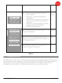
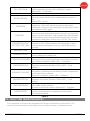
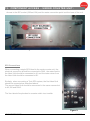
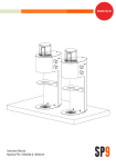
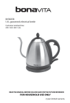
1
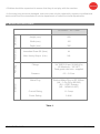
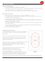
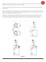
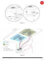
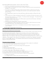
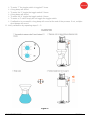
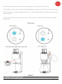
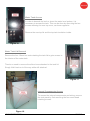
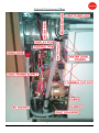
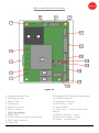
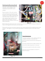
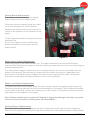
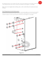
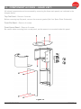
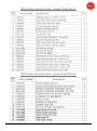
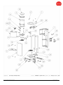
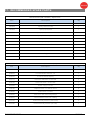
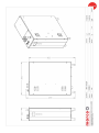
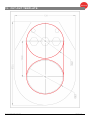
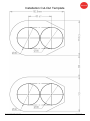
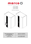
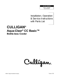
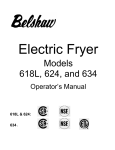
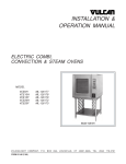
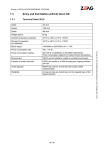
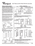
SP9 System – Twin & Single (#1000830, #1000831, #1000832, #1000833) SERVICE MANUAL Marco Beverage Systems Ltd. 63d Heather Road, Sandyford Industrial Estate, Dublin 18, Republic of Ireland SP9 ServiceManual.docx 06/02/2015 Ireland Tel: (01) 295 2674 Ireland Fax: (01) 295 3715 UK Tel: (0207) 274 4577 UK Fax: (0207) 978 8141 Page 1 of 42 CONTENTS: CONTENTS 1) Introduction ………………………………………………………………….. 3 2) Safety Instructions …………………………………………........................ 3 ………………………………………………………….. 4 4) Installation ………………………………………………………………….. 5 5) Setup and Calibration ………………………………………….. 8 6) Overview & Operation ………………………………………………….. 10 ………………………………………………………….. 13 8) User Setup Options ………………………………………………….. 14 9) Service Setup Options ………………………………………………….. 15 10) Diagnostics ………………………………………………………………….. 17 11) Display Status Messages ………………………………………………….. 18 ………………………………………………….. 19 3) Specifications 7) Menu Navigation 12) Routine Maintenance 13) Component Access – Under Counter Unit ………………….. 22 ………………………………….. 29 15) Electrical Schematic ………………………………………………….. 31 16) Spare Parts Schematic ………………………………………………….. 33 17) Recommended Parts List ………………………………………………….. 38 ………………………………………………….. 39 ………………………………………….. 41 14) Component Access – Head Unit 18) Dimensioned Drawings 19) Installation Cut-Out Template SP9 ServiceManual.docx 06/02/2015 Page 2 of 42 1. INTRODUCTION: The information provided in this manual is intended to assist in the installation and maintenance of the Marco SP9 System, consisting SP9 Boiler and either one or two SP9 Head Units (Single/Twin). Please read the instructions carefully to prevent accidents and ensure an efficient installation. This manual is not a substitute for any safety instructions or technical data affixed to the machine or its packaging. All information in this manual is current at the time of publication and is subject to change without notice. Only technicians or service providers authorised by Marco Beverage Systems should carry out installation and maintenance of these machines. Marco accepts no responsibility for any damage or injury caused by incorrect or unreasonable installation or operation. 2. SAFETY INSTRUCTIONS: When using electrical appliances, basic safety precautions should always be followed to prevent the risk of fire, electric shock, burns or other injuries or damages. • Read all operating and safety instructions carefully. • This machine must be earthed. If the moulded plug supplied is not used then ensure that the green/yellow cable is connected to a suitable earth. • Risk of flooding: The hose supplied with the boiler is non-toxic food quality tested to 190psi. However, a hose is not a permanent connection. It is, therefore, advisable to switch off boiler and close the stopcock valve when boiler is not in use. e.g. overnight, etc. • The utmost care has been taken in the manufacture and testing of this machine. • Failure to install, maintain and / or operate this machine according to the manufacturer’s instructions may result in conditions that can cause injury or damage to property. If in any doubt about the serviceability of the machine always contact the manufacturer or your own supplier for advice. • This machine is not intended for use by persons (including children) with reduced physical, sensory, or mental capabilities, or lack of experience and knowledge, unless they have been given supervision or instruction concerning use of the appliance by a person responsible for their safety. SP9 ServiceManual.docx 06/02/2015 Page 3 of 42 • Children should be supervised to ensure that they do not play with the machine. • In the event any wires are damaged, such wires can only be replaced by experts or professional service staff from the manufacturer service department or similar functional departments. 3. SPECIFICATIONS: Height (mm) 565 Width (mm) 155 Depth (mm) 395 Immediate Draw-Off (litres) 4L Max. Hourly Output (L/hr) 24L Fittings 3/4” BSP5-50 psi (35-345 kPa) US Machines – 3/8” NPT Food grade inlet hose - supplied Pressure 0.5 – 5.0 bar Mains Plug Earthed Mains Plug to IEC 230vac (UK – 3-Pin Plug, BS1363) (EU – CEE7 Schuko) (US - NEMA L6-20P) Current Rating 11.5 amp Power Rating 2.4kW Electrical Plumbing Performance Dimensions SP9 Boiler - 4L / 2.4kW Table 1. SP9 ServiceManual.docx 06/02/2015 Page 4 of 42 4. INSTALLATION: Electrical I nstallation: Electrical specification: 2.4kW-230VAC-50/60Hz A moulded 13A IEC power cord is provided. This should be plugged into the IEC connection on the base of the boiler and plugged into a suitable 13A power outlet. When installing the machine, always observe the local regulations and standards. Plumbing Installation : Mains water pressure required (limits): 5-50psi (35-345kPa) 0.5 – 5.0 bar Fit a stop Valve on a cold water line and attach a 3/4" BSP male fitting, (e.g. 3/4" x 1/2" 311 or washing machine type stop valve). For US versions use 3/8” NPT male fitting. Connect straight tailpiece of the hose to the stop valve fitting. Make sure that the preattached sealing washer is fitted. Turn on the water to flush any impurities, dust etc. from the inlet hose and water pipe. Allow several litres through. Connect right-angled tailpiece of the hose to the inlet valve of the boiler (3/4" BSP). Make sure the sealing washer is fitted here also. Turn on water and check for leaks. Installation of SP9 Head Unit: A full A4 sheet sized version of the counter cut-out template, seen opposite in Figure 1, can be found on the last page of this manual. The cut-out is simply two 80mm holes centred 83mm apart. Alternatively, the area outlined in red, bounded by the two circles and the parallel lines (obround shape) can be cut out using a jig-saw or similar. Once the cut-out is complete, mount the SP9 Head Unit using the brackets supplied. See Figure 3, below. Use the appropriate rubber spacers on the brackets to match the thickness of the counter. Attach the electrical connector and the two hoses to the appropriate ports on the under counter unit. A goes to A, B goes to B and DIN goes to DIN. For a Single Head System, use A1, B1 and DIN1. For a Twin Head System, connect Head Unit 1 as in a Single Head System. Connect Head Unit 2 to A2, B2 and DIN2. The hoses should be secured with the supplied hose clips. The Undercounter Unit should ideally be positioned directly below the Head unit installed position. SP9 ServiceManual.docx 06/02/2015 Page 5 of 42 When mounting Twin Head Units, ensure a minimum of 100mm between units, not just between cut-outs, as indicated in Figure 2, below. The distance between the SP9 Head Unit and the Under Counter unit should be NO MORE than 400mm. Max distance between head and boiler refers to the length of the tubing. Since the tubing is never a straight line, actual distance between head and boiler can be substantially less than 400mm, depending on alignment of units. Drainage – Connect drip tray, boiler vent and head vent to a drain via a tundish or some other method of open connection to drain. Do not connect these three outlets together in a closed configuration using T-piece or double T-piece. Always allow these to “breath”. Figure 2. SP9 ServiceManual.docx 06/02/2015 Page 6 of 42 Figure 3. Figure 4. SP9 ServiceManual.docx 06/02/2015 Page 7 of 42 Operating SP9 Undercounter Unit for the First Time: Check that all installation procedures have been carried out. Ensure water is connected to unit, valve is turned on and power cord is connected and plugged in to wall socket. The “power on” light will glow green and the machine will fill to a safe level, above the elements, before heating. The display will show the current water temperature and the status “Filling…” The “Ready/Status” light will cycle two red flashes while the machine is filling to the safe level. After this amount of water has heated to about 94ºC, the boiler will draw more water in until the temperature drops by 1 or 2 degrees. The boiler will then heat again. This heat fill cycle continues until the boiler is full. Ensure the Undercounter unit is set to SP9 mode for use with the SP9 brewer. See Menu Navigation section in this manual While filling, the “Ready/Status” light will remain blank. The “Ready/Status” light will glow green when the machine is both full and up to normal operating temperature. Allow approximately 15 minutes. The boiler is now ready for use – the display will show the Water Temperature and the status “READY”. 5. SETUP AND CALIBRATION: Operating the Head Unit for the first time: To help prevent heat loss between the Undercounter unit and the Head unit the silicone hose can be insulated with hose insulation. Simply cut the insulation to the correct length required. Once the Head Unit installation procedure has been carried out, place a 1 litre jug under the dispense head. Set the dispense volume to 750ml and press the start switch twice. This will dispense 750ml in one delivery, without pausing. Measure the dispensed volume to confirm factory calibration (750ml + 10ml). If the volume is not satisfactory, proceed to the calibration procedure below to calibrate the Head Unit. The calibration should only be conducted by a trained service engineer. See guidelines below. Dispense Volume Calibration 1. Once all installation procedures are carried out the Head Unit is ready to be calibrated. 2. Turn volume dial to Max. Set Brew Time to 2 minutes. 3. Place large container (>1 litre) of known weight under spray head. 4. Initiate brew. 5. Weigh & record brew output. 6. The output should be 750g, plus or minus 10g. 7. If output is within 10g of 750g calibration is complete. 8. If not, enter calibration mode by holding down toggle switch for min 3 sec. 9. A long beep will sound to confirm the unit is in calibration mode. 10. Enter the volume recorded via the brew switch using the following example: If 724g was measured The toggle switch is used to input each digit successively SP9 ServiceManual.docx 06/02/2015 Page 8 of 42 To enter ‘7’ the toggle switch is toggled 7 times A long beep will sound To enter the ‘2’ toggle the toggle switch 2 times A long beep will sound To enter the ‘4’ toggle the toggle switch 4 times To enter a ‘0’ value simply do not toggle the toggle switch. If calibration is successful a long beep will sound at the end of the process. If not, multiple short beeps will sound 11. Verify calibration by repeating steps 2 – 5. Figure 5. SP9 ServiceManual.docx 06/02/2015 Page 9 of 42 6. OVERVIEW & OPERATION: SP9 – EFFORTLESS EXCEPTIONAL COFFEE BY THE CUP SP9 is a single-portion brewer designed to deliver volumes from 150ml to 750ml. It is designed to work with several different existing brewing devices from Kalita right through to Chemex. SP9 also has a Continuous Dispense Mode for filling tea pots or other hot beverage vessels. SP9 can be configured as a Twin System, with two head units operating independently from a single under counter unit. SP9 can also be configured as a Single System, with a single head unit operating with a single under counter unit. In brew mode, once the brew switch is toggled, SP9 will recirculate hot water for 15 seconds to preheat the system. It will then start to dispense water in 9 pulses. The first pulse is 12% of the total volume selected, designed as a pre-infusion stage. The remaining 8 pulses are all of equal volume of 11% of total volume selected. Water Volume can be varied from 150ml to 750ml. Brew Time can be varied from 1 to 5 minutes. The under-counter unit can deliver 100 to 120 cups of water per hour at a flow rate of 1.3 litres/min. Before brewing you should become familiar with the SP9 system controls. SP9 ServiceManual.docx 06/02/2015 Page 10 of 42 CONTROLS Figure 6. BREWING SP9 ServiceManual.docx 06/02/2015 Page 11 of 42 Select the required volume of water to be dispensed, using the upper control knob. Select the brew time, also referred to as the dispense or contact time, using the lower control knob. Start the brew by pressing the toggle switch once. Three beeps will be heard when the brew cycle has completed. For continuous dispense mode, select the volume of water to be dispensed and press the toggle switch twice. Brewing Figure 7. 7. MENU NAVIGATION: SP9 ServiceManual.docx 06/02/2015 Page 12 of 42 Undercounter Unit Modes of Operation Ensure the Undercounter unit is set to SP9 Mode for use with the SP9 head unit. The SP9 Undercounter Unit has many settable features which gives the operator greater flexibility in choosing how the unit will operate. Main screen There are two Menus in the SP9 Undercounter Unit: • USER SETUP. • SERVICE SETUP Entering Setup Mode SP9 ServiceManual.docx 06/02/2015 Page 13 of 42 • To enter setup mode press power and eco buttons on the front panel at the same time. • The display will show “USER SETUP” message: • Release the buttons now to enter the USER SETUP mode. • To enter advanced settings (Service Setup) keep the buttons pressed until the display shows “SERVICE SETUP” message and release them. • In both setup modes use front panel buttons to navigate the settings: • Power button to scroll through the functions, • Eco button to increase set value (press and hold for auto-repeat). 8. USER SETUP OPTIONS: The default temperature setting is 95° The user can set the temperature of the tank. Use the navigation instructions above to change the temperature. NOTE: Temperature should never be set for more than 96°C as it may cause steam to be generated during low pressure days. Screen view Description Default value Sets new tank temperature. Range: 60 – 98.5 °C (Default 95°C) Resolution: 0.5 °C 93.0 Sets dispense time. Range: 0 – 99.9 seconds Resolution: 0.1 second For PUSH & HOLD mode set to 0 (Default). 00.0 Sets number of pauses during time dispense. Range: 0 – 20 If machine set as PUSH & HOLD then number of pauses has no impact on dispense. 00.0 Sets pause time (same for each of the pauses). Range: 0 – 20.0 seconds Resolution: 0.1 second If machine set as PUSH & HOLD then time of pause has no impact on dispense. 00.0 Press the eco button to save all the values and reboot the machine. SP9 ServiceManual.docx 06/02/2015 Page 14 of 42 9. SERVICE SETUP OPTIONS: Screen view SP9 ServiceManual.docx 06/02/2015 Description Default value No. 1 Sets and shows remaining weeks before de-scaling is needed (“DESCALE TANK” message on the screen). Setting it to OFF will disable the function. Range: 1 – 60 weeks OFF No. 2 Sets and shows remaining litres of water before filter change is needed (“CHANGE FILTER” message on the screen). Setting it to OFF will disable the function. Range: 100 – 9900 litres OFF No. 3 Sets the time for which the inlet opens every time the machine needs water. It minimises temperature fluctuations. The value should be picked to allow 0.5 - 1°C cooling after water intake and depends on the tank size and element power. This is a factory setting and should only be changed by trained personnel. Range: 0 – 20.0 seconds Resolution: 0.1 second 3.0 No. 4 Sets the time at which machine waits for the water too cool down after water intake. Measured from the beginning of the water intake. The value depends on tank size and element power. This is a factory setting and should only be changed by trained personnel. Range: 0 – 60.0 seconds Resolution: 0.5 second 12.0 No. 5 “SERV PIN” limits access to SERVICE SETUP, setting it to 0000 disables the pin (default) Back-Door PIN is 1793 OFF No. 6 PIN entry screen - once PIN is set and user wants to access SERVICE SETUP this screen will pop up. Use top button to move through positions and bottom to scroll through the values (0 to 9 and again 0); if PIN is accepted you will gain access to the SERVICE SETUP, if PIN is rejected machine will reboot itself. 0000 Page 15 of 42 No. 7 Sets the mode the machine works in: SP 9 - Default HEAT FILL (minimises temperature fluctuations), CONT FILL (continuous fill – makes sure the tank is always full but temperature may vary), COOL FILL (allows cooling but reduces tank size by using ECO mode), MANUAL (manual filling). No. 8 Sets temperature units on screen. Celsius or Fahrenheit No.9 This sets max limit of the temperature that user can set in USER SETUP; max value is 98.5 degrees Celsius SP 9 Celsius 98.5 No.10 Press the eco button to save all the values and reboot the machine. Table 3. 10. DIAGNOSTICS: The SP9 under counter unit is controlled by a processor-based embedded system which monitors different aspects of the equipment. If a fault is detected, the ready light will flash red a number of times, pause, and then repeat the flashes, as long as the fault is detected. A list of faults, corresponding to the number of flashes between each pause, can be seen below. SP9 ServiceManual.docx 06/02/2015 Page 16 of 42 Table 4. 11. DISPLAY STATUS MESSAGES: Status BOILER OFF FILLING ... SP9 ServiceManual.docx 06/02/2015 Description Machine off. Display backlight off but temperature readout still working. Water level below low level probe. Machine is filling automatically. Status LED – 2 red blinks. Page 17 of 42 FILL THE TANK WAIT ... BOILER READY DISPENSE COOLING ... DISPENSE WATER TO COOL THE TANK DESCALE TANK CHANGE FILTER CHECK LOW PROBE THERMISTOR S/C ELEMENT FAILURE THERMISTOR O/C LOW PRESSURE COMM ERROR Water level below low level probe. Machine has to be refilled manually (shown only in MANUAL mode). Status LED – 2 red blinks. Water is being heated. Dispense valve disabled. Water is up to the temperature and can be used. Note that this only means that the tank is heated and not that it is full. Status LED – green. Water is being dispensed. If machine is set to time dispenses – there will also be a progress bar drawn underneath. Dispense can always be cancelled by clicking the dispense button again. Machine was set by the user to a lower temperature than the current tank temperature and is trying to cool down by taking in more cold water. This process may take between 20 seconds to a few minutes depending on tank size and temperature difference. Works only in COOL FILL mode. Machine cannot take more cold water to cool the tank because it is full. Water needs to be dispensed to allow room for more cold water to come in and finish cooling process. Descale timer elapsed. Time to descale the tank. Litres output exceeds set value. Time to change the water filter. Low water level probe broken (disconnected). Machine detects high level probe signal but cannot detect low level one. Filling is disabled. Status LED – 1 red flash. Temperature sensor (thermistor) is short circuited. Dispense and heater disabled. Status LED – 3 red flashes. Heating element is broken. Error is triggered when after 20 minutes of heating and not taking in water temperature in the tank fails to increase. Dispense is disabled. Status LED – 4 flashes. Temperature sensor (thermistor) is disconnected. Dispense and heater disabled. Status LED – 5 red flashes. Incoming water pressure too low. The error will be reset after water supply restores. All boiler functions are active. Status LED – 6 flashes. Display board lost communication with boiler PCB (cannot receive serial data about temperature and probes). All actions cancelled. Table 5. 12. ROUTINE MAINTENANCE: It is a common occurrence for limescale to build up in the tank of a water boiler. The amount of limescale build up is relative to the water hardness in a particular area. SP9 ServiceManual.docx 06/02/2015 Page 18 of 42 The most common error indication on a boiler is the Ready light giving two red flashes between pauses, indicating that water can’t be seen in the tank. This can be caused by a number of issues, most commonly, limescale or film build up on the water level probes. Descaling Procedure: Isolate machine from power supply. Isolate machine from water supply. ALLOW TO COOL COMPLETELY! Drain water from machine. Remove all lids. Remove as much scale as possible by hand, paying particular attention to level probes (White plastic with steel tab). Be very careful not to damage any attachments. Use ScaleKleen, Marco part No. 8000270 or similar. Follow instructions carefully. Thoroughly clean and flush the machine before re-use. Clean water level probes with ScotchBrite Follow installation and first time operation instructions NB: Always clean the water level probes after descaling and rinsing the tank. To Clean Water Level Probes: Turn off water feed to unit Dispense as much water from unit as possible using two clicks at the head unit Turn off unit at wall socket or unplug from wall socket Remove top cover from boiler Remove tank lid from tank Identify water level probes – flat metal tabs inside water tank - 3 probes Thoroughly clean probes with ScotchBrite (or scouring pad) Replace tank lid and top cover Reconnect power and water to boiler and operate as normal SP9 ServiceManual.docx 06/02/2015 Page 19 of 42 SP9 ServiceManual.docx 06/02/2015 Page 20 of 42 SP9 ServiceManual.docx 06/02/2015 Page 21 of 42 13. COMPONENT ACCESS – UNDER COUNTER UNIT: Access to the IEC socket (230vac/13A) and the water connection point is at the base of the unit. Figure 8 - Base of SP9 Undercounter Unit SP9 Connections When connecting a single SP9 Head to the under counter unit, the electrical connection should be connected to DIN1, the water feed to the Head Unit should be connected to A1 and the water return from the Head Unit should be connected to B1. Similarly, when connecting a Twin SP9 system, the first Head Unit should be connected as described above. The second Head Unit should be connected in the same manner but to A2, B2 and DIN2. The Vent should be plumbed to a waste outlet via a tundish. Figure 9. SP9 ServiceManual.docx 06/02/2015 Page 22 of 42 Water Tank Access In order to descale the tank or clean the water level probes, it is necessary to access the tank. This can be done by removing the two screws retaining the rear top cover, as shown opposite. Remove the rear top lid and the top tank insulation inside. Figure 10. Water Tank Lid Removal Remove the four 10mm hex nuts retaining the tank lid to gain access to the interior of the water tank. There’s no need to remove the silicon hose attached to the tank lid. Simply fold it back out of the way while still attached. Figure 11. Internal Components Access To access the internal components and wiring, remove the side panel by first removing the four cross-head retaining screws. Figure 12. SP9 ServiceManual.docx 06/02/2015 Page 23 of 42 Internal Component Map Figure 13. SP9 ServiceManual.docx 06/02/2015 Page 24 of 42 Main Control Board Connections Figure 14. 1. Dispense Solenoid Tab 2. Inlet Solenoid Tab 3. Neutral Tabs 4. Transformer 5. Mains Live In Tab 6. Relays - Heater 7. Heater Tab 8. On/Off 2-way Connector (Link Inserted 9. LED 5-way Connector 10. Earth Tab SP9 ServiceManual.docx 06/02/2015 11. Daughter PCB Connector (low voltage) 12. External Connector 13. Thermistor Connector 14. DIP Switch – 3 way 15. Tactile Switch 16. Water Level – 5-way connector (low voltage) 17. Button Connector – 4-way 18. Data I/O Connector – 4-way 19. Relays – Inlet Solenoid Page 25 of 42 Replacing the Main Control Board If the main control board needs to be replaced, note the position of all connections and the DIP-switch settings. Remove power to the under counter unit and remove all connections from the main control board. Using a pillar release tool (or a BIC biro with the refill removed) release each pillar in turn while applying slight pressure to the back of the control board. Once all pillars have been released, remove the board completely. Figure 15. Before fitting the replacement main control board, ensure the DIP-switch settings correspond to those of the original control board, as noted earlier. Ensure all connections have been replaced in the correct positions before applying power to the machine. The diagram on the previous page details all connection points on the main control board. Pump Replacement To remove a pump, cut the retaining cable ties, unplug the electrical connections and remove the silicon hose from the outlet port on the pump. The pump is push-fit and is held in place by the seal and the siphoning action of the pump. Pull or pry the pump from the seal to remove. Follow the instructions above in reverse to replace the pump. Figure 16. SP9 ServiceManual.docx 06/02/2015 Page 26 of 42 Display Board Replacement Remove the ribbon cable from the display board. Remove the four retaining nuts. When removing the display board, be careful not to lose any spacers, as the distance between the display board and front panel is critical to the operation of the switches on the board. Fit the replacement board and replace the four retaining nuts. Do not over-tighten, as this will affect the distance between the front panel and the display board. Figure 17. 24vdc Power Supply Replacement Disconnect power to the under counter unit. The cable connections can be removed before removal of the 24vdc power supply or after the retaining screws have been removed, depending on access and preference. The 24vdc power supply is retained on its mounting bracket by two screws, accessible from the bottom of the bracket. Remove the two screws (and the cable connections, if applicable) and remove the 24vdc power supply. Replace the 24vdc power supply and the cable connections. Ensure the connections are replaced back in to the correct terminals. Water Level Probes Replacement To replace the water level probes, empty the tank and gain access through the tank lid opening. Disconnect the wiring harness from the outer threading part of the probe. While holding the probe on the inside of the tank, remove the retaining nut on the outside. The probe can now be removed and replaced. See diagram on next page. Note: Probes should only be replaced if leaking or physically damaged. Usually, any probe issues can be resolved by cleaning them with ScotchBrite. Heating Element Replacement To replace the heating element, empty the tank and gain access through the tank lid opening. Disconnect the spade connectors from the outer connectors of the heating element. While holding SP9 ServiceManual.docx 06/02/2015 Page 27 of 42 the heating element on the inside of the tank, remove the retaining nuts and seals on the outside. The heating element can now be removed and replaced. See diagram on next page. Note: Do not over-tighten the retaining nuts, as this could deform the seals and cause leakage. Over-Temperature Cut-Out Replacement To replace the over-temperature cut-out switch, remove the spade connectors from the switch. Remove the two retaining nuts and remove the switch. When replacing, use a little thermal conductive paste to ensure good thermal conductivity. See diagram on next page. Figure 18. SP9 ServiceManual.docx 06/02/2015 Page 28 of 42 14. COMPONENT ACCESS – HEAD UNIT: All internal components can be accessed by removing the three main panels, as indicated in the diagram below. Top Flat Panel – Remove 3 screws Before removing top flat panel, remove the reservoir gasket (No.9 on Spare Parts Schematic). Front Flat Panel – Remove 4 screws Front Curved Panel – Remove 2 screws Be careful when removing front curved panel, as the reservoir is mounted inside this panel. Figure 19. SP9 ServiceManual.docx 06/02/2015 Page 29 of 42 Head Unit Control Board Replacement Remove the front curved panel, as described previously. It should be possible to achieve sufficient clearance for removal of the control board without having to disconnect the tubing from the reservoir. Disconnect the cable connection from the control board. Remove the adjustment knobs and retaining nuts from the adjustment pots. Remove the head unit control board from inside the head unit. Replace the control board by following the preceding instructions in reverse. Reservoir and Solenoid Replacement Remove the front curved panel, as described previously. Disconnect the wires from the solenoid. Remove the tubing from the bottom of the solenoid and the three tubes from the bottom of the reservoir. Remove the retaining nuts and silicone spacers from the reservoir. The solenoid is attached by pushing it in to the silicone mounting seal in the reservoir. Remove the solenoid from the reservoir by pulling the two apart while twisting them. When replacing the reservoir or solenoid, follow the instructions above in reverse. Figure 20. SP9 ServiceManual.docx 06/02/2015 Page 30 of 42 15. ELECTRICAL SCHEMATICS: SP9 ServiceManual.docx 06/02/2015 Page 31 of 42 SP9 ServiceManual.docx 06/02/2015 Page 32 of 42 16. SPARE PARTS SCHEMATICS: SP9 ServiceManual.docx 06/02/2015 Page 33 of 42 SP9 Under-Counter Unit – Spare Parts Part 1 SP9 Under-Counter Unit – Spare Parts Part 2 SP9 ServiceManual.docx 06/02/2015 Page 34 of 42 SP9 ServiceManual.docx 06/02/2015 Page 35 of 42 SP9 ServiceManual.docx 06/02/2015 Page 36 of 42 SP9 Head Unit – Spare Parts SP9 ServiceManual.docx 06/02/2015 Page 37 of 42 17. RECOMMENDED SPARE PARTS: SP9 Head Unit (P/N: 1000830) - Spare Parts Part Description Qty 1860200 SP9 Reservoir 1 1860202 Splurty Reservoir Cap 1 1860203 Splurty Sprayhead 1 1860227 Splurty Sprayhead Chemex 1 1860207 Splurty Reservoir gasket 1 1860214 Splurty Basket holder 1 1860253 Splurty drip tray insert 1 1502163 Valve 12mm Bore 24VAc 30E Vent Vend 1 1600385 PCB Splurty Dials 1 1800735 Knob - dial 2 1501932 Switch Toggle Mom 1 1402160 Tailpiece Hose 1/4" BSP X 12mm 6 SP9 Under-Counter Unit (P/N: 1000831) - Spare Parts Part Description Qty 1501559A Pump Topsflo 24V 2 1600375 P.C.B Ecoboiler Control - UL 1 1600357 P.C.B EcoSmart Display 1 1501177 Harness Lead Boiler 3 core DIN 2 1502192 Valve Inlet 240V - 2Lmin NSF 1 1601000 Power supply 24V DC 1 1402160 Tailpiece Hose 1/4" BSP X 12mm 8 2100350 Drain Valve 1/4'' BSP 2 1500950 Element 2.4kW 230V Ring Shape 1 1502075 Thermal Switch Dual Pole 125deg 1 2301463 Probe Assembly SubCon (40mmTab) 2 2301460 Probe Assembly SubCon (No Tab) 1 SP9 ServiceManual.docx 06/02/2015 Page 38 of 42 18. DIMENSIONED DRAWINGS: SP9 ServiceManual.docx 06/02/2015 Page 39 of 42 SP9 ServiceManual.docx 06/02/2015 Page 40 of 42 19. CUT-OUT TEMPLATE: SP9 ServiceManual.docx 06/02/2015 Page 41 of 42 Installation Cut-Out Template SP9 ServiceManual.docx 06/02/2015 Page 42 of 42