1
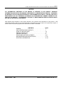
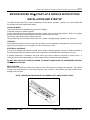
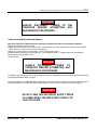
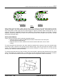
MICROSCRAPER™ 500 CONVEYOR
PARTS AND SERVICE MANUAL
Thank you for choosing an LNS Chip Conveyor. We are proud to have you among our LNS family of users.
LNS Chip Conveyors simply and reliably remove waste from machining operations. Machine efficiency is increased
and operator safety is improved since chip conveyors work with little operator attention and without interrupting
production time. LNS conveyors are available for many types of machine tools or other applications. They can be
arranged to deliver wet or dry waste to containers or to conveyor or chute-type disposal systems. LNS also offers
tramp oil removal systems, which are over 99% effective, to increase coolant and tool life. In addition, centralized
3-D disc conveyors are available for further reduction in indirect labor, which add greatly to your plant efficiency and
profitability. For further information, contact:
Inside Sales Department
LNS TURBO
203 Turbo Drive
Kings Mountains, NC 28086
This Service Manual is intended to assist with the normal maintenance that will assure long service life of your LNS
Chip Conveyor. It is in two parts – a Service Instruction Section, followed by a Parts Section, which includes
drawings and parts lists for the basic elements of the conveyors.
©MARCH 2004 – LNS ........................................................................... PUBLICATION NO. 864510-0007 REV. 01
Page 1
TURBO MICROSCRAPER 500® CONVEYOR PARTS AND SERVICE MANUAL
NOTICE
ALL INFORMATION CONTAINED IN THIS MANUAL IS INTENDED TO BE CORRECT; HOWEVER
INFORMATION AND DATA IN THIS MANUAL ARE SUBJECT TO CHANGE WITHOUT NOTICE. LNS MAKES
NO WARRANTY OF ANY KIND WITH REGARD TO THIS INFORMATION OR DATA. FURTHER, LNS IS NOT
RESPONSIBLE FOR ANY OMISSIONS OR ERRORS OR CONSEQUENTIAL DAMAGE CAUSED BY THE
USER OF THE PRODUCT. LNS RESERVES THE RIGHT TO MAKE MANUFACTURING CHANGES, WHICH
MAY NOT BE INCLUDED IN THIS MANUAL.
LNS supplies data necessary for the proper instruction, test, operation and maintenance of this product. LNS
retains all proprietary rights in and to the information so disclosed and such shall not be reproduced, copied, or
used in whole or in part for purposes other than those for which it is furnished.
CONTENTS
GENERAL. . . . . . . . . . . . . . . . . . . . . . . . . . . . . . . . . . . . . . . . .
PART ORDERING AND WARRANTY . . . . . . . . . . . . . . . . . . .
START-UP INSTRUCTIONS . . . . . . . . . . . . . . . . . . . . . . . . . .
PERIODIC INSPECTION . . . . . . . . . . . . . . . . . . . . . . . . . . . . .
TROUBLE SHOOTING . . . . . . . . . . . . . . . . . . . . . . . . . . . . . . .
REPAIR AND PARTS REPLACEMENT. . . . . . . . . . . . . . . . . .
MICROSCRAPER 500® SERVICE PARTS . . . . . . . . . . . . . . .
ELECTRICAL INFORMATION . . . . . . . . . . . . . . . . . . . . . . . . .
PAGE
1
2
3-4
5-7
8
9-16
17-20
21-22
©MARCH 2004 – LNS ........................................................................... PUBLICATION NO. 864510-0007 REV. 01
Page 2
TURBO MICROSCRAPER 500® CONVEYOR PARTS AND SERVICE MANUAL
INSTRUCTIONS FOR ORDERING PARTS
Furnish the following information on your order:
• Model and serial no. of machine
• Catalog number and name of part
• Quantity wanted
• Purchase order number
• Bill to address
Furnish exact shipping instructions:
∙ Complete shipping address
∙ Mode of delivery
∙ Parcel post, truck line, etc
How to find the model and serial number of your machine:
The machine model number and serial number is stamped on the machine nameplate located on the motor cover.
DIRECT YOUR ORDER TO:
LNS Turbo
203 Turbo Drive
Kings Mountains, NC 28086 U.S.A.
Telephone: (704) 739-7111 Fax: (704) 739-6039
WARRANTY
Seller warrants that within 12 months from original shipment or 18 months from installation, which ever comes first,
if its products are operated by the original specified user: Seller will repair or replace, at its option, free of charge
except freight, FOB shipping point, any parts it finds nonconforming on these conditions:
a. on request, user promptly allows seller to inspect, and user returns all requested parts to seller’s plant, and
b. user has operated and maintained products in accordance with seller’s maintenance and operational
literature and good business practice; and
c. products have not been misused, abused, damaged by accident or altered without seller’s written consent;
and
d. user employs trained maintenance and operating personnel; and
e. buyer meets all payment obligations;
Seller warrants products manufactured by others to the extent warranted by their original manufacturers, on these
conditions. Parts, which have expected life shorter than one year under normal usage, are excluded.
USED PRODUCTS ARE SOLD AS IS. SELLER MAKES NO WARRANTY FOR USED PRODUCTS EXCEPT AS
TO TITLE. BUYER MAY INSPECT AND TEST BEFORE SHIPMENT AND ACCEPTS USED PRODUCTS ON
THESE TERMS.
THIS WARRANTY IS EXCLUSIVE AND IN LIEU OF ALL OTHER WARRANTIES WHETHER WRITTEN, ORAL,
OR IMPLIED, (INCLUDING ANY WARRANTY OF MERCHANTABILITY OR FITNESS FOR PARTICULAR
PURPOSE.)
©MARCH 2004 – LNS ........................................................................... PUBLICATION NO. 864510-0007 REV. 01
Page 3
TURBO MICROSCRAPER 500® CONVEYOR PARTS AND SERVICE MANUAL
MICROSCRAPER 500® START-UP & SERVICE INSTRUCTIONS
INSTALLATION AND STARTUP
Your LNS Conveyor has been run prior to shipment to insure proper operation. However, it is recommended that
the following checks be made before startup:
CONVEYOR DRIVE
Check frame and belt for damage during shipment or storage.
Locate the conveyor in operating position.
All drive elements (pulleys and sprockets) should be located close to their bearing supports. Each set of pulleys
and sprockets should be carefully aligned to prevent excessive wear and noise.
Drive chains and belts should be properly tensioned.
Check speed reducer to see that oil is at proper level. If there is a shipping plug in gearbox vent, remove it.
LEVELING
Level should be placed across tail section and on bottom cover at discharge, perpendicular to travel of the belt.
Adjust conveyor support leg, if so equipped, or shim as necessary to level.
ELECTRICAL CONTROLS
If conveyor is supplied with electrical controls, check voltage of system supplied to be sure it matches with that to
be used. Read the Electrical Controls section in this manual for more details before installing the conveyor.
A qualified electrician in accordance with local codes must connect electrical equipment to power source. If
conveyor power source is basic machine, refer to basic machine manufacturers wiring diagram.
DO NOT DRILL HOLES IN CONVEYOR FRAME TO MOUNT POWER BOXES OR ACCESSORIES WITHOUT
FIRST CONSULTING LNS.
BELT ROTATION
Always check for proper belt rotation upon start up of the conveyor prior to putting it into operation. If the belt is
running in the wrong direction it will not carry chips out of the conveyor. This condition can result in failure and/or
damage to the conveyor.
NOTE: ARROWS BELOW INDICATE THE CORRECT BELT DIRECTION OF TRAVEL
©MARCH 2004 – LNS ........................................................................... PUBLICATION NO. 864510-0007 REV. 01
Page 4
TURBO MICROSCRAPER 500® CONVEYOR PARTS AND SERVICE MANUAL
SCRAPER BELT ROTATION
DANGER!
ALWAYS DISCONNECT POWER TO
CONVEYOR BEFORE ATTEMPTING
MAINTENANCE PROCEDURES.
THE
ANY
LUBRICATION AND ROUTINE MAINTENANCE
After First 100 Hours of Operation and at regularly scheduled intervals to suit operating conditions:
Check belt brushes for excessive wear.
Inspect conveyor belt parts for excessive wear. If excessive wear is noted, belt should be removed and repaired.
(Refer to service section for belt removal instructions).
Change oil in speed reducer (if applicable). Use any brand 90-wt. gear oil.
Grease pillow block bearings, using grease gun. Do not grease too often – bearing seals could be damaged.
Check belt tension (see page 4 & 5).
Oil drive chains.
DANGER!
ALWAYS DISCONNECT POWER TO
CONVEYOR BEFORE ATTEMPTING ANY
MAINTENANCE PROCEDURES.
In addition to the following, please read the separate Conveyor Installation and Start-up Instructions furnished with
your MICROSCRAPER 500® conveyor.
Prior to installation of the MICROSCAPER 500®, the coolant tank should be cleaned of any chip residue from prior
machining operations or debris from shipment packaging. This will ensure a clean and trouble free start-up.
DANGER!
DO NOT TURN ON ELECTRICAL SUPPLY PRIOR
TO COMPLETING THE PRE-START CHECK LIST
THAT FOLLOWS.
©MARCH 2004 – LNS ........................................................................... PUBLICATION NO. 864510-0007 REV. 01
Page 5
TURBO MICROSCRAPER 500® CONVEYOR PARTS AND SERVICE MANUAL
MICROSCRAPER 500® START-UP
COOLANT FILLING
Fill the coolant tank with water soluble coolant solution of your choice. After initial start-up, you may find it
necessary to add coolant to restore the desired fluid level. This is because the conveyor load section acts as an
additional reservoir and complete drain down of the conveyor does not occur even during system idle periods.
Note: Do not fill the coolant tank level with coolant above the maximum fill level indicated on your coolant tank.
WHEN TO OPERATE THE MICROSCRAPER 500® CONVEYOR
The MICROSCRAPER 500® conveyor should always operate whenever the machine tool is running or the
coolant pumps are operating! Failure to do so may cause severe damage to the conveyor belt and/or to the
filtration box!
PERIODIC INSPECTION
DANGER!
DO NOT REACH INTO THE CONVEYOR WHEN THE
SYSTEM IS RUNNING BECAUSE IT HAS MOVING
PARTS. SERIOUS PERSONAL INJURY COULD
RESULT.
FILTRATION BOX ASSEMBLY INSPECTION
The filter box assembly(s) should be free of dents, tears or other damage that would result in chips bypassing the
filter box. In the event that the filter box is damaged, it must be replaced immediately. Failure to do so will result in
contamination of the clean side of the tank.
Prior to running the conveyor after the inspection, be sure to remove any tools, shop rags or towels you may have
used while completing inspection and maintenance. Any foreign article(s) left inside the conveyor frame can cause
an immediate lock-up at re-start. This may lead to failure of the belt components, filter boxes and/or gear-drive.
CONVEYOR BELT TENSIONING
Correct conveyor belt tension is essential to ensure proper operation and extended life of conveyor components.
The belt has been properly tensioned during factory assembly. As normal wear occurs the belt may become slack
and need adjustment.
The following factors may be used to determine if the belt needs adjustment.
•
•
•
Belt Is Too Loose: Belt Slack at exit point of the drive sprocket before re-entry into frame. (See fig. 1).
Belt Is Too Tight: Belt has intermittent jerks and a popping sound while conveyor is in operation.
Uneven Tension (side to side): (1) Belt tends to track to one side.
©MARCH 2004 – LNS ........................................................................... PUBLICATION NO. 864510-0007 REV. 01
Page 6
TURBO MICROSCRAPER 500® CONVEYOR PARTS AND SERVICE MANUAL
INCORRECT
CORRECT
FIG. 1
When checking the belt tension, using a pair of vise grip pliers, clamp on one of the formed cleats on the belt.
Using the vise grips, “rock” the belt back and forth to feel the slack and drag on the belt. There should not be more
than enough slack to allow rocking the drive shaft through 15 degrees of rotation without moving the belt. On a
new belt, zero slack is acceptable, but if the belt is difficult to move with the vise grips, it is too tight. Correctly
adjusted, it should be possible, even if difficult, to move the belt by hand when turning the driven sprocket. (Always
wear gloves during this step)!
DRIVE CHAIN TENSION
Proper Tension for the drive chain is extremely important because:
1. When the chain is too tight, the additional load results in faster wear on the chain joints,
sprocket teeth and shaft bearings.
2. When the chain is too slack, vibration could cause excessive chain wear, noise or shock
loading.
For most horizontal and incline drives, the chain should be installed with an amount of sag in the unloaded span
amounting to about 2 percent of the sprocket center distance length. Sag, then, becomes the measure of chain
tension. For example if the span length between the sprocket centerlines, as shown below, are 18” then the sag
should be 3/8” if the belt is tensioned correctly.
To measure the actual amount of sag, one side of the chain should be pulled up tight, allowing all of the excess
chain to accumulate in the opposite span. A straight edge over the sprockets and a scale can be used to measure
the sag. The chain tension should be checked on a regular basis and adjustments made as necessary.
©MARCH 2004 – LNS ........................................................................... PUBLICATION NO. 864510-0007 REV. 01
Page 7
TURBO MICROSCRAPER 500® CONVEYOR PARTS AND SERVICE MANUAL
MOTOR AND DRIVE SHAFT & SPROCKET ALIGNMENT
Proper alignment of sprockets and shafts are essential for smooth operation of conveyors and long lasting service
of the conveyor chain and the drive chain. To ensure correct alignment, follow these steps.
1. Level the motor and drive shaft using a level.
2. Align the motor and drive shaft for parallelism using a straight edge or a scale. The sprocket should be parallel
to the shaft within +/- 1 mm.
3. Align the motor sprocket with the clutch or drive sprocket axially on the shafts using a straight bar, straightedge
or stretched wire as illustrated below. Centering accuracy should be within 2 mm.
©MARCH 2004 – LNS ........................................................................... PUBLICATION NO. 864510-0007 REV. 01
Page 8
TURBO MICROSCRAPER 500® CONVEYOR PARTS AND SERVICE MANUAL
TROUBLE SHOOTING
The following chart will show some problems, their probable causes and possible solutions.
PROBLEM
(1) Fines build-up
on filter screens:
POSSIBLE CAUSE
POSSIBLE SOLUTION
(a) Brushes are not contacting filtration box
screens:
Readjust brush(es) to proper height to contact
filtration box screens or replace brush(es) if worn out.
(b) Deformed screen on the filtration box
assembly:
Replace filtration box.
(2) Low coolant
flow or over-flow
of load section
baffles:
(a) Plugged filter box assembly.
Clean the filtration box after removal. (See the
section titled "Removing Filter Box").
(3) Deteriorating
fines removal
efficiency:
(a) Damaged or worn filtration box
assembly.
Replace the filtration box. (See the section titled
"Removing Filter Box").
(b) Improper seal of filtration box.
Remove and replace gasket.
(a) Overload relay in drivemotor control
circuit has tripped out.
Reset overload relay.
(b) Overload relay is undersized for the
amp. draw of the motor. (See amp draw
chart in electrical section of this manual
for conveyor motor amp. draw.
Replace overload relay with correct size for the
conveyor drive motor.
(c) Conveyor belt is broken.
Repair damaged section or replace belt.
(d) Sheared shaft key at drive motor
sprocket
Replace failed parts AFTER determining cause of
failure;
(e) Worn-out drive sprockets, excessively
loose or broken drive chain
Replace worn or broken parts.
(f) Motor drive chain is either broken or
chain tension is too loose.
Repair chain or properly tension chain per
instructions in this manual.
(5) Belt is pulsating
or surging:
(a) Belt tension is either too tight or too
loose.
Properly tension belt per instructions in this manual.
(6) Excessive wear
of belt
components:
(a) Belt tension is either too tight or too
loose.
Properly tension belt per instructions in this manual.
(b) Improper alignment of drive sprockets
or tail sprocket.
Properly align sprockets per instructions in this
manual.
(c) Conveyor is not level or square.
Properly level conveyor per instructions in this
manual.
(a) Conveyor is not level or square.
Properly level conveyor per instructions in this
manual.
(b) Belt tension is either too tight or too
loose.
Properly tension belt per instructions in this manual.
(4) Belt is not
moving.
(7) Excessive wear
of the conveyor
frame:
©MARCH 2004 – LNS ........................................................................... PUBLICATION NO. 864510-0007 REV. 01
Page 9
TURBO MICROSCRAPER 500® CONVEYOR PARTS AND SERVICE MANUAL
MICROSCRAPER 500® FILTER BOX REPAIR & PART REPLACEMENT
TROUBLESHOOTING THE SCRAPER CONVEYOR
A.
If overflowing occurs, or if large chips appear in the clean side of the coolant tank:
1.
Under either condition, the most probable cause is a plugging of the filter box weldment. This can be
determined by observing the difference in fluid level within the conveyor while the conveyor is in operation
and the machine running and generating chips. Approximately once every minute, the coolant level should
drop noticeably in the conveyor. This is as a result of a brush wiping across the surface of the filtration box.
Should the brush no longer be effective at wiping the surface, it indicates that the brushes may need
adjustment or replacement.
2.
One entire revolution of the belt should be observed. The easiest way of doing this is to stop the conveyor,
mark one cleat and watch a full rotation of the belt. If there is a noticeable difference between the levels
that the coolant drops approximately every minute, it probably indicates that only a few brushes need
adjustment or replacement.
3.
If the coolant level appears to be at a very high level in the conveyor, and there is little noticeable drop in
the level of coolant in the conveyor, then it would indicate that all brushes need replacement.
DANGER!
THE FILTRATION BOX ON MOST OF THESE CONVEYORS RUNS BELOW FLUID
LEVEL – DO NOT INSERT YOUR HANDS BELOW FLUID LEVEL ON THESE
CONVEYORS. MOVING PARTS ARE PRESENT AND SERIOUS INJURY COULD
RESULT.
FILTRATION BOX ASSEMBLY REPLACEMENT AND REMOVAL/ASSEMBLY
REMOVING THE FILTRATION BOX
1.
To determine whether or not the filtration box surface is clogged, the filtering box (Item 3 as shown below)
will have to be removed from the conveyor. On some machines this may be accessible without removing
the conveyor from the coolant tank of the machine. On other machines it may be necessary to remove the
entire conveyor to gain access to the box.
©MARCH 2004 – LNS ........................................................................... PUBLICATION NO. 864510-0007 REV. 01
Page 10
TURBO MICROSCRAPER 500® CONVEYOR PARTS AND SERVICE MANUAL
2.
There is always one, and there may be more than one, filtration boxes. Each box should be examined for
plugging of the screen material that acts as a filter.
3.
CAUTION !
TAKE CARE IN HANDLING THE FILTRATION BOX SO THAT THE SURFACE IS NOT PUNCTURED,
NOR THE BOX DROPPED. THIS IS A PRECISION FABRICATED WELDMENT AND FOR PROPER
FUNCTIONING, THE BOX MUST BE HANDLED CAREFULLY. ANY HOLES IN THE FILTERING
MATERIAL WILL RESULT IN THE LOSS OF FILTRATION AND EFFECTIVENESS OF THE
CONVEYOR.
4.
To remove the filter box, remove the six nuts, washers and lock washers (Items 4, 5 and 6 shown above.
Slide the filter box out from the flanged side. Inspect the flange gasket (Item 2 shown above) to insure it is
not damaged. If so replace the gasket before reassembly. Failure to do so can result in poor filtration
efficiency of the conveyor.
5.
After removal of the box, if fine material is on the bottom surface of the box (the filtering surface), it would
indicate that the material is not being removed via the self-cleaning brushes.
6.
After removal of all loose material on the surface, inspect the box to determine if any fine elements have
wedged themselves in the holes in the filtering element. Remove these prior to reinstalling the box.
PROCEDURE FOR REINSTALLATION OF THE FILTRATION BOX.
1.
After cleaning the box in the manner described above, make sure that the area in which the box is mounted
inside the conveyor is free of any debris and chips because the box has to seat inside the conveyor frame
and must be a water-tight joint. Epoxy or gasket cement should be used with the gasket and the box
tightened down in a three-step process so as not to distort the frame. Take care not to overtighten bolts.
Compression of the gasket is all that is required.
NOTE: If only one side of the box has a screened filtering element, be certain that the box is installed with
the screened element DOWN.
REPLACEMENT OF FILTRATION BOX GASKET
See “Filtration Box Assembly Replacement and Removal/Assembly Filter Box” section above for procedures to
replace filtration box gasket.
ADJUSTMENT OF BRUSHES
If the filtration box(es) are getting clogged and coolant is overflowing the conveyor baffles, the brushes should be
inspected to insure that they are making proper contact and cleaning the filtration surface of the filtration box. The
proper heights of the brushes are shown in the diagram below.
To adjust the brush heights follow this procedure:
©MARCH 2004 – LNS ........................................................................... PUBLICATION NO. 864510-0007 REV. 01
Page 11
TURBO MICROSCRAPER 500® CONVEYOR PARTS AND SERVICE MANUAL
1. Position the belt so that the brush is almost against the edge of the filtration box.
2. The entire bottom portion of the brush should be making contact with the filtration surface of the filtration box.
However, the leading edge of the brush should be making only light contact with the filtration box surface. (See
the diagram below for proper setting). If it is not, the brush should be adjusted closer to the box until the entire
bottom surface of the brush is making contact with the filtration box surface.
3. To adjust the brush, loosen the brush mounting bolts and slide the brush to the proper position as shown on the
diagram below. Retighten the bolts when properly positioned. In case the adjustable slots in the brush are
bottomed out against the mounting bolts before it is properly positioned, it is time to replace the brush.
DANGER!
ALWAYS DISCONNECT POWER TO CONVEYOR BEFORE ATTEMPTING
ANY MAINTENANCE PROCEDURES. FAILURE TO DO SO MAY CAUSE
SERIOUS PERSONAL INJURY.
©MARCH 2004 – LNS ........................................................................... PUBLICATION NO. 864510-0007 REV. 01
Page 12
TURBO MICROSCRAPER 500® CONVEYOR PARTS AND SERVICE MANUAL
REPLACEMENT OF BRUSHES
In case the brushes are worn excessively or damaged, the following procedure should be following when replacing
them:
1. Position the belt so that the brushes (item # 1 shown below) and mounting hardware (items # 2, 3, 4 & 5 as
shown below) are accessible.
2. Remove the mounting hardware and discard the old brush.
3. Mount the new replacement brush per the diagram below.
NOTE: Never reuse the Nylock Hex Nuts (Item # 4 as shown below) after they have been tighten and
loosened one time. Once these nuts are loosened the nylon insert is no longer effective. The nuts
must always be replaced once they are loosened. Failure to replace these nuts can result in the
brushes coming loose and/or falling off. This can lead to a conveyor jam, damage to the conveyor belt,
damage to the filtration boxes and/or loss of effectiveness of the conveyor.
4.
Once the brushes are mounted follow the procedure for “Adjustment of Brushes” in this manual.
DANGER!
ALWAYS DISCONNECT POWER TO CONVEYOR BEFORE ATTEMPTING
ANY MAINTENANCE PROCEDURES. FAILURE TO DO SO MAY CAUSE
SERIOUS PERSONAL INJURY.
©MARCH 2004 – LNS ........................................................................... PUBLICATION NO. 864510-0007 REV. 01
Page 13
TURBO MICROSCRAPER 500® CONVEYOR PARTS AND SERVICE MANUAL
MICROSCRAPER 500® BELT REMOVAL AND INSTALLATION INSTRUCTIONS
1. Disconnect power to the conveyor before performing any work on the belt. This should only be done by a
licensed and qualified electrician who is properly trained in all applicable local, state and national safety codes.
2. Remove the cover for the drive chain, bearing, discharge cover and incline cover if necessary.
3. Remove the master link from the roller drive chain, which runs between the motor sprocket and the drive shaft
sprocket and remove the chain.
4. Loosen the lock nuts on the belt tension adjusting screws (located just behind each of the pillow block bearings
on the drive shaft) and back off the adjusting screws until they are flush with the face of the adjusting bracket.
5. Loosen the two bolts holding each pillow block bearing.
©MARCH 2004 – LNS ........................................................................... PUBLICATION NO. 864510-0007 REV. 01
Page 14
TURBO MICROSCRAPER 500® CONVEYOR PARTS AND SERVICE MANUAL
6. Slide the drive shaft toward the tail of the conveyor as far as the adjusting slots for the pillow block bearings will
allow. This will provide maximum slack in the belt. Locate the connecting links which are located on the belt
(on short length conveyors there are two locations, on longer conveyors four). If possible run the belt so that
the connecting links are at the discharge end for ease of removal. Remove the connecting links on either side
of the belt and feed a few feet out of the top flight to prepare for belt removal. (NOTE: the removal of the belt is
made in the opposite direction of normal belt travel). At this point you should also note the direction of the
cleats and brushes so you have the belt marked for proper orientation when reinstalling it or a replacement.
This step is CRITICAL for proper re-installation later.
7. Grasp the end of the belt below the drive shaft and pull the belt out of the conveyor. Be sure to wear gloves to
avoid being cut by sharp edges on the belt. When only a few feet of belt remain in the conveyor, the belt on the
floor will have enough weight to begin pulling the remainder out on it’s own. As the last of the belt begins to run
out faster, do not attempt to stop it. Just stand clear and let it run out onto the floor.
©MARCH 2004 – LNS ........................................................................... PUBLICATION NO. 864510-0007 REV. 01
Page 15
TURBO MICROSCRAPER 500® CONVEYOR PARTS AND SERVICE MANUAL
8. Place the new belt on the floor beneath the conveyor discharge, being carefully to orient it in the same direction
as the old belt that was removed.
9. If there are not already connecting links at the end of the belt, use the connecting links that were removed to
separate the old belt. New cotter pins should be used for reliability.
10. With a person standing on either side of the belt, lift up the lead end and start it in the upper track, from which
the old belt was pulled out. Be sure and wear gloves to prevent injury, and be sure to maintain a secure hold
on the belt until at least five feet has been fed into the conveyor frame. At this point, the weight of the belt
inside the frame should be enough to prevent it running back out on it’s own.
11. Continue feeding the belt into the conveyor frame. It will be necessary for one person to guide the leading end
of the belt through the proper track sections in the load and incline portions of the conveyor. In both of these
sections the track for the upper flight of the belt is not solid and the proper installation has the belt against the
upper most track in the upper flight and the lower most track on the bottom flight.
12. When the lead end of the belt reaches the drive shaft, carefully feed it up over the drive sprockets.
13. With the ends of the belt engaged in the teeth around the top and bottom of the drive sprockets, the two ends
must be joined. At this point, it may be necessary to remove one or more links from the new belt. Most new
belts are supplied longer than necessary.
©MARCH 2004 – LNS ........................................................................... PUBLICATION NO. 864510-0007 REV. 01
Page 16
TURBO MICROSCRAPER 500® CONVEYOR PARTS AND SERVICE MANUAL
14. Reverse steps 1 through 7.
15. When adjusting the belt tension, using a pair of vise grip pliers, clamp on one of the formed cleats on the belt.
Using the vise grips, “rock” the belt back and forth to feel the slack and drag on the belt. There should not be
more than enough slack to allow rocking the drive shaft through 15 degrees of rotation without moving the belt.
On a new belt, zero slack is acceptable, but if the belt is difficult to move with the vise grips, it is too tight.
Correctly adjusted, it should be possible, even if difficult, to move the belt by hand when turning the driven
sprocket. (Always wear gloves during this step)!
16. Visually confirm that the belt is located in the center of the frame. Adjust if necessary by loosening the setscrews in the pillow block bearings and shifting the drive shaft assembly to the left or the right as appropriate.
17. Re-connect the power using only a licensed or properly qualified electrician who is properly trained in all
applicable local, state and national safety codes. The belt should run freely and the only sound should be a
subdued clicking as each drag bar passes over the drive sprocket.
18. Check to insure the belt is running in the proper direction as shown below.
DANGER!
ALWAYS DISCONNECT POWER TO CONVEYOR BEFORE ATTEMPTING
ANY MAINTENANCE PROCEDURES. FAILURE TO DO SO MAY CAUSE
SERIOUS PERSONAL INJURY.
©MARCH 2004 – LNS ........................................................................... PUBLICATION NO. 864510-0007 REV. 01
Page 17
TURBO MICROSCRAPER 500® CONVEYOR PARTS AND SERVICE MANUAL
MICROSCRAPER 500® SERVICE PARTS LIST
HORIZONTAL LOAD SECTION ASSEMBLY
MICROSCRAPER 500®
©MARCH 2004 – LNS ........................................................................... PUBLICATION NO. 864510-0007 REV. 01
Page 18
TURBO MICROSCRAPER 500® CONVEYOR PARTS AND SERVICE MANUAL
HORIZONTAL LOAD SECTION ASSEMBLY
©MARCH 2004 – LNS ........................................................................... PUBLICATION NO. 864510-0007 REV. 01
Page 19
TURBO MICROSCRAPER 500® CONVEYOR PARTS AND SERVICE MANUAL
MICROSCRAPER 500®
DRIVE AND DISCHARGE SECTION PARTS LIST
©MARCH 2004 – LNS ........................................................................... PUBLICATION NO. 864510-0007 REV. 01
Page 20
TURBO MICROSCRAPER 500® CONVEYOR PARTS AND SERVICE MANUAL
MICROSCRAPER 500®
DRIVE AND DISCHARGE SECTION ASSEMBLY
©MARCH 2004 – LNS ........................................................................... PUBLICATION NO. 864510-0007 REV. 01
Page 21
TURBO MICROSCRAPER 500® CONVEYOR PARTS AND SERVICE MANUAL
MICROSCRAPER 500® ELECTRICAL INFORMATION
LNS Chip Conveyors are supplied with a variety of drive packages and electrical controls, depending on conveyor
application and customer preference. Only a qualified electrician or machine service technician should perform any
maintenance, repairs or adjustments on this equipment.
WARNING!
ONLY QUALIFIED ELECTRICIAN OR SERVICEMAN SHOULD
TROUBLESHOOTING OR MAINTENANCE TO THIS EQUIPMENT.
PERFORM
ANY
ELECTRICAL
DO NOT PERFORM ANY MAINTENANCE, REPAIRS OR ADJUSTMENTS ON THIS EQUIPMENT WITHOUT
FIRST LOCKING OUT ALL ELECTRICAL CONTROLS.
PERSONNEL SHOULD BE TRAINED IN OSHA COMPLIANT LOCK-OUT/TAG-OUT AND ELECTRICAL
SAFETY PROCEDURES.
MAKE CERTAIN THAT THE POWER SUPPLY IS DISCONNECTED BEFORE ATTEMPTING TO SERVICE OR
REMOVE ANY COMPONENTS!
AT NO TIMES SHOULD CIRCUIT CONTINUITY BE CHECKED BY SHORTING TERMINALS WITH A
SCREWDRIVER OR OTHER METAL DEVICE.
NEVER SHOULD ADJUSTMENTS, MAINTENANCE OR CLEANING BE PREFORMED WITHOUT FOLLOWING
PROPER SAFETY PROCEDURES IN ACCORDANCE WITH LOCAL, STATE AND NATIONAL SAFETY
CODES.
Before making any electrical connections be certain the voltage for which the conveyor drive and control are wired
is the same as incoming voltage being delivered by the electric power supply. Failure to do so may result in injury
or damage to the equipment. It may be necessary in the case of 220/440V, 3 phase, for example, to change the
motor wiring from one voltage to another. Normally a wiring diagram is located inside the motor terminal box, which
indicates proper wiring for the incoming voltage supplied.
Some machines are equipped with internal electrical controls and a multi-pin type accessory plug for connecting the
chip conveyor. LNS Conveyors can be ordered with a mating plug, so that connecting the conveyor is as simple as
plugging it in.
The best and most common source of power for the chip conveyor is the machine electrical cabinet. It is the
customer’s responsibilities at the time of order to determine what, if any, electrical components are present and/or
order the appropriate conveyor control.
Even if the machine has no plug or other provision for connecting a chip conveyor, the conveyor should be ordered
from LNS with both halves of a quick-disconnect style plug. One half will come pre-wired to the conveyor control
cable. The other half of the plug will be wired to the machine electrical cabinet where it will be connected to the
power supply. The chip conveyor can then be quickly unplugged for cleaning or service without having to
disconnect “hard wired” connections.
Before starting the chip conveyor, check to be sure no tools, packing, or other material have been left on the belt or
in the discharge opening, Start the conveyor and verify proper direction of belt travel. Reverse polarity if the belt is
moving in the wrong direction.
©MARCH 2004 – LNS ........................................................................... PUBLICATION NO. 864510-0007 REV. 01
Page 22
TURBO MICROSCRAPER 500® CONVEYOR PARTS AND SERVICE MANUAL
TIME DELAY DEVICES
The use of a time delay device is prohibited on a Microscraper 500® Conveyor. If the conveyor is not running when the
machine tool is cutting chips it may cause a large chip build up in the conveyor frame. When the conveyor is finally
turned on it may not be able to handle the chip load. This condition may cause belt, frame and/or filter damage to the
Microscraper 500® Conveyor. It is imperative that the Microscraper 500® Conveyor is operating continuously
whenever the machine tool is cutting chips. LNS will not be responsible for damage caused to the conveyor when a
time delay device is being used.
AC CURRENT REQUIREMENTS
All Microscraper 500® Conveyors
Voltage
3PH Line-Line
Belt Drive Type
Belt Drive
Horsepower
Current per phase
at Rated Load
Recommended Overload
Relay Setting
208VAC
Fixed Speed
¼
0.84A
0.90A
230VAC
Fixed Speed
¼
0.84A
0.90A
460VAC
“
¼
0.42A
0.45A
SHOCK RELAY
The conveyor is protected by a shock relay, which is located inside of the conveyor control box. The shock relay is
preset at the factory. If the shock relay trips out, do not change the amperage setting or the response time of the
shock relay without consulting with LNS’ Service Department. Please check the instructions below for setting the
shock relay to insure it is set correctly. If so, the conveyor drive motor amperage has exceeded the normal
overload amperage setting in the shock relay. Normally, if the conveyor trips the shock relay after a successful run
period there is some type of conveyor jam, which must be cleared before continuous conveyor operation can be
resumed. Refer to the trouble-shooting guide in this manual to assist with determining the possible cause of the
problem. Failure to correct this problem and continue conveyor operations will result in the conveyor filling up with
chips. This may cause damage to the conveyor and will definitely add increased downtime to clean out the
conveyor.
SETTING THE SHOCK RELAY INCORRECTLY CAN CAUSE DAMAGE TO THE CONVEYOR, WHICH WILL
NOT BE COVERED UNDER WARRANTY!
INSTRUCTIONS FOR SETTING SHOCK RELAY
1. Set start time to 2 seconds.
2. Set current at maximum
3. Set shock time to minimum.
4. Start conveyor, push test. Conveyor should stop. Push Rest.
5. Restart conveyor, turn load current down slowly until the conveyor stops.
6. Adjust the load current up slightly.
7. Adjust start time down slightly. Start the conveyor. If the shock relay trips adjust the start time back up.
©MARCH 2004 – LNS ........................................................................... PUBLICATION NO. 864510-0007 REV. 01