1
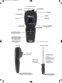
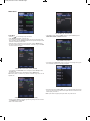
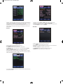
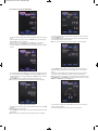
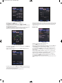
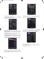
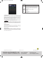
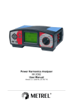
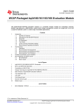
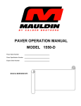
TE-UHH_SSS-1000 7/19/12 10:08 AM Page 1
Bulletin TE-UHH
Model UHH - Universal Handheld Test Instrument
Specifications - Installation and Operating Instructions
3.038
[77.17 mm]
2.169
[55.09 mm]
8.508
[216.11 mm]
Front View
Side View
The Model UHH Universal Handheld Test Instrument is a highly versatile
instrument that offers the utmost flexibility and ease of user operation by having
the capacity to work with a variety of Dwyer Instruments, Inc. compatible sensing
modules and probes. Additional wired and wireless probes or modules are
instantly recognized by the UHH without any user reprogramming or alteration,
allowing seemless sensor addition, upgrade or replacement. See the Dwyer
Instruments, Inc. catalog or website www.dwyer-inst.com for available packages
and sensors. The Universal Handheld offers a slew of features that enable a
technician to quickly set up and intuitively navigate through their daily activities.
Data is stored via the internal memory or separate SD card in various auto or
manual logging operations. Logged files can be quickly transferred to a device
through a USB cable or by a portable SD card. The display can operate in standard
numerical meter mode, gauge mode with analog needle and bar graph, gauge
mode with additional pass/fail operation zones, and strip chart mode which
enables a simplified visual tracking of the process. The four button directional plus
enter button combined with the three soft key buttons aligning to corresponding
screen functions allow for quick navigation through the four main operation menus.
The rugged plastic case with protective thermo-plastic over-mold along with the
dust-shielding rubber caps permit the unit to handle abuse and properly withstand
dusty environments. The base UHH includes an integral molded compartment,
that securely holds wireless modules. The storage compartment offers convenient
transportation of a module with the base instrument during testing. A flexible hand
strap included with every UHH provides means for the base handheld to be safely
connected to a belt, pipe, ladder or similar structure freeing the user's hands to
focus on the sampling test. A 6-pin connector enables one wired probe at a time
to be plugged in to the base instrument without worry of becoming disconnected
during sampling. The rechargeable battery via the included USB cable provides
long term operation to last through several days work. At just under 10 oz, the
compact UHH base is lightweight. Included in the standard series kits is a soft
carrying case which secures the provided accessories and test probe. The ProSeries provides the addition of a rugged hard case with foam cut-outs that secures
existing as well as additional test sensors and accessories.
*Wireless Guidelines in Accordance with FCC:
Changes not expressly approved by Dwyer Instruments Inc. could void the user's
authority to operate the equipment.
This product complies with FCC OET Bulletin 65 radiation exposure limits set forth
for an uncontrolled environment.
Pursuant to FCC 15.21 of the FCC rules, changes not expressly approved by
Dwyer Instruments, Inc. might cause harmful interference and void the FCC
authorization to operate this product.
Canadian Government Guidelines:
Operation is subject to the following two conditions: (1) This device may not cause
harmful interference and (2) this device must accept any interference received,
including interference that may cause undesired operation.
UHH SPECIFICATIONS
Languages: German, Spanish, Italian,
English, Portuguese.
Display: OLED, color 240 x 320.
Temperature Limits: 5 to 125°F (-15
to 51°C).
Note: When using wireless
function: 20 to 125°F (-6 to 51°C).
Battery Charging Limits: 32 to 113°F
(0 to 45°C).
1 FPM, 0.1 MPS, 0.1
Resolution:
3
CFM & M /HR; 0.1°F & °C; RH 0.1%.
Units Air Velocity: FPM, MPH, KN,
M/H, M/S K/H, FPS. 3
3
Units Flow: CFM, M /HR, M /S, GPM,
GPH, GPD, LPS, LPM, LPH.
Units Temperature: °F, °C.
Handle Enclosure: Thermoplastic
elastomer over polycarbonate.
Maximum Wireless Distance: 50’
(15 m) typical.
Power Requirements: Rechargeable
lithium ion polymer via USB.
Weight: 10 oz (283 g).
Supplied With:
AQTI: Soft case; USB cable/
charger; Hand strap;
AQTIP: Soft case; Hard case; USB
cable/charger; Hand strap, 2GB
SD card.
Agency Approval: IEC 61000-4-2,
IEC 61000-4-3, EN 55022, IEC 606011-2, EN 300 328, CE with approved
charger, RoHS; Note: Intended to be
operated with power cables less than
3 m in length, *FCC Compliance.
THERMO ANEMOMETER PROBE
SPECIFICATIONS
Service: Air velocity and temperature
of clean, dry air.
Temperature Limits:
Process Air Velocity: -20 to 212°F
(-29 to 100°C);
Process Temperature: -40 to 212°F
(-40 to 100°C).
Ambient: 5 to 125°F (-15 to 51°C).
Wireless Probe Battery Charging
Limits: 32 to 113°F (0 to 45°C).
Range Air Velocity: 0 to 6000 FPM (0
to 30 m/s).
Accuracy Air Velocity: ±3% FS
within temperature range of 40 to 90°F
(4 to 32°C).
Range Volumetric Air Flow: 999,999
in selected flow units.
Range Temperature: -40 to 212°F
(-40 to 100°C).
Accuracy Temperature: ±0.5°F
(±0.28°C) from 32 to 122°F (0 to
50°C); ±1.5°F (±0.83°C) from -40 to
32°F (-40 to 0°C) and 122 to 212°F
(50 to 100°C).
Handle Enclosure: Thermoplastic
elastomer over polycarbonate.
Probe Length: 8˝ (203 mm) insertion.
Cable Length: 28˝ (71 cm) retracted,
6 ft (183 cm) extended.
Supplied With: Wrist strap.
Agency Approval: EN 55011, EN
61326-1, IEC 61000-4-2, IEC 610004-3, EN 55022, RoHS, *FCC
Compliance.
HUMIDITY/TEMPERATURE PROBE
SPECIFICATIONS
Service: Humidity and temperature
detection in clean air.
Temperature Limits:
Process: -22 to 176°F
(-30 to 80°C);
Ambient: 5 to 125°F (-15 to 51°C).
Wireless Probe Battery Charging
Limits: 32 to 113°F (0 to 45°C).
Range Relative Humidity: 0 to 100%
(non-condensing).
Accuracy Relative Humidity: ±2%
FS over 10 to 90% @ 77°F (25°C).
Range Temperature: -22 to 140°F
(-30 to 60°C).
Accuracy Temperature: ±0.9°F @
72°F (±0.3°C @ 25°C).
Handle Enclosure: Thermoplastic
elastomer over polycarbonate.
Probe Length: 8˝ (203 mm) insertion.
Cable Length: 28˝ (71 cm) retracted,
6 ft (183 cm) extended.
Supplied With: Wrist strap.
Agency Approval: EN 61000-6-2, EN
61000-6-4, IEC 61000-4-2, IEC
61000-4-3, EN 55011, EN 61326-1,
RoHS, *FCC Compliance.
INFORMATION TO THE USER
Power Output: 6 mW
Operating Frequency: 2.4 GHz
Operating Channel: 11
Operating Mode: IEEE 802.15.4, Zigbee, Direct Sequence Spread Spectrum
Data Rate: Up to 250 kbps
Intended Use: Industrial/commercial HVAC
Antenna Connection: Internal only, non-tunable
DWYER INSTRUMENTS, INC.
P.O. BOX 373 • MICHIGAN CITY, INDIANA 46360, U.S.A.
Phone: 219/879-8000
Fax: 219/872-9057
www.dwyer-inst.com
e-mail: [email protected]
TE-UHH_SSS-1000 7/19/12 10:08 AM Page 2
UHH FEATURE OUTLINE
SD MEMORY
CARD SLOT
PROTECTIVE RUBBER CAPS
INDUSTRIAL 6-PIN
PROBE CONNECTION
HAND STRAP
TOP CLIPS
SENSOR AND LOGGING
ICON LOCATION
BATTERY
INDICATOR
LARGE BACKLIT
COLOR OLED
MAIN MENUS
ACTIVE PROBE
NUMBER INDICATOR
3 SOFT KEYS CORRESPOND
TO APPLICABLE ON-SCREEN
FUNCTIONS
4 DIRECTIONAL ARROWS
WITH ON/OFF/ENTER BUTTON
ALLOW QUICK NAVIGATION
LED INDICATES CHARGING
STATUS AND DATA STORAGE
GREEN: INDICATES CHARGING.
NOTE: TURNS OFF WHEN
FULLY CHARGED. YELLOW:
INDICATES A DATA POINT
STORAGE OR THAT UNIT IS IN
SLEEP MODE.
HAND STRAP BOTTOM CLIP
SIDE VIEW
WIRELESS PROBE
MODULE STORAGE
COMPARTMENT
POWER BUTTON:
Hold for 5 seconds
until LED turns RED
and then release to
power OFF.
USB CONNECTION FOR DATA
TRANSFER OR RECHARGING WITH
INTEGRAL PROTECTIVE RUBBER CAP
LED INDICATES STATUS:
• Solid Green: Battery
charging
• Blinking Green:
Communicating with UHH
• Blinking Amber (short):
Waiting for communications
with handheld
• Blinking Amber (long):
Probe initializing
• Solid Red: Low battery
USB CONNECTION FOR
RECHARGING WITH INTEGRAL
PROTECTIVE RUBBER CAP
TE-UHH_SSS-1000 7/19/12 10:08 AM Page 3
MENU SETUP
Probe Main Menu
Probe Menu
• Press the
to scroll through the top main menus.
• When PROBE is highlighted, hit the enter key.
• The currently active probe connected will appear as well as the parameter types
being provided to the UHH. ACTIVE will detail the active probe’s description, model
code and corresponding serial number.
• Select the primary measurement of the home screen under the MAJOR setting.
• To alter the potential modes of the measurements, scroll down to any of the TYPE
sub-menus to select and adjust.
Area Sub Menu (Vol. Flow Selected)
• If Vol. Flow is chosen, select the AREA category to adjust the DUCT style, the
AREA UNITS, HEIGHT and WIDTH dimensions.
TYPE Sub-Menu Temperature
• In this example, the Temperature range is set and cannot be changed as it is green
and unselectable, however the units may be adjusted.
TYPE Sub-Menu Anemometer (Velocity Selected)
• In this example, the Anemometer can be changed from either Velocity mode or
Vol. Flow mode.
• Change the engineering units to be displayed under the UNITS section.
Note: Some probes or modules may provide a selectable range which can be
adjusted here.
Pairing Mode Sub-Menu
• After placing the UHH into Pairing Mode, turn on one wireless probe. After a period
of up to 15 to 20 seconds, the UHH screen will update with the information about the
wireless probe just turned on.
Note: If probe does not appear, power probe down, then power back on.
TYPE Anemometer Sub-Menu (Vol. Flow Selected)
• Similarly to when Velocity is selected, applicable engineering units can be chosen
in the UNITS category for Vol. Flow.
• Note an area must be entered.
TE-UHH_SSS-1000 7/19/12 10:09 AM Page 4
Pairing Mode Sub-Menu (cont’d)
• To confirm a proper pairing, select that probe on the list. That probe’s details will
disappear, meaning that probe has been paired. The details of paired probes will
now be visible in the Paired sub-menu. Once paired, no other UHH can pair with
that probe as long as your UHH is communicating with that probe.
• In Paired sub-menu you can see probes that are paired with the UHH. You may
delete probes from being paired by selecting. Once deleted, any UHH can pair
with that probe.
SETTINGS Sub Menu
• Click on the SETTINGS sub menu for language selection as well as the default
engineering units. The DATE and TIME can be entered, as well as power
management inactivity time delays for SLEEP and SHUTDOWN.
• The user can program in their name, an identification code or their company name
into the SETTINGS sub menu under OWNER.
VIEW Menu
SYS Menu
VIEW METER Mode
SYS Main Menu
• Press the
to scroll through the top main menus.
• When SYS is highlighted, push the enter key.
• The STATUS will show how many probes are currently paired.
• The WIRELESS feature may be turned on or off and the display CONTRAST
adjusted here as well.
• If desired, a RESTORE DEFAULT feature is available from this screen.
• Note: FILE displays remaining available memory. If INT is selected in the LOG
main menu the maximum memory is 4 MB. A 2 GB memory card is the maximum
memory the UHH can utilize if SD is selected.
Status Sub Menu
• If you select the STATUS sub menu you can view the firmware edition as well as
the UHH device handle.
• Press the
to scroll through the top main menus.
• When VIEW is highlighted, select with the enter key.
• Several viewing modes are available on the home screen from the selections in
this menu.
• The default is METER which displays numerical values.
• The AVERAGE setting calculation is programmed in this menu.
• AVERAGE values may be altered from 1 to 60 seconds.
TE-UHH_SSS-1000 7/19/12 10:09 AM Page 5
Home Displays Under Standard METER Mode
CURR View in the Home Screen
• On the home display, multiple values may be viewed at the same time if a sensor
offers.
• If two are present the reading at the top, or MAJOR reading, may be switched.
See the Probe main menu for details.
• Press the soft key on the left aligned with the HOLD function to freeze the
reading at that instant. The RUN function will then appear on the left.
• To resume reading the live process press the left soft key aligned with the RUN
function.
PEAK VALLEY Home Screen
• To view the peak and valley values, press the middle soft key one more time to
scroll from TOTAL to P/V.
• Hit the CLEAR soft key on the right to instantly reset the peak and valley values
and recalculate new peak and valley values.
Note: The current process reading will remain visible at the top of the display.
View GAUGE Mode
AVG Home Screen
• To see the average reading instead of the current process reading press the soft
key in the middle aligned with the CURR function so that the AVG function is on
top. Press the soft key on the right aligned with the CLEAR function to reset the
average readings.
• See the VIEW main menu to adjust the average function time period.
Note: The current process reading will remain visible at the top of the display.
• Choose GAUGE mode to display a digital analog gauge like one similar to a
speedometer. The available range will be adjustable with min and max scale
feature.
• Adjust both the min and max for the associated values that will correspond to
the 0° value for min and the 180° value for the max or full scale reading.
Note: Some probes or modules may have selectable ranges that are programmed
in the PROBE menu under RANGE. You cannot go above this chosen full scale
RANGE in the GAUGE setting in the VIEW menu.
Home View GAUGE Mode
TOTAL Summation Home Screen
• To view the sum or total value, again press the middle soft key to scroll from AVG
to TOTAL.
Note: Only visible on certain probes.
• Hit the CLEAR soft key on the right to reset the total value back to zero and restart
the summation.
Note: The current process reading will remain visible at the top of the display.
• In this example, the min is zero and the max is 500. The live process value is
shown under the gauge dial.
• The mid point will always show at the 90° point on the gauge dial.
TE-UHH_SSS-1000 7/19/12 10:09 AM Page 6
View RANGE Mode
Home View STRIP Mode
• An extension from the GAUGE mode is the RANGE mode.
• Select RANGE in the VIEW category.
• Two sets of min and max will appear listed as GAUGE and RANGE.
• The GAUGE settings are just as in the previous GAUGE view mode and show the
zero and full scale points of the dial.
• The RANGE low and high settings provide a different color green zone to appear
on the dial of the digital gauge. This two color band dial provides a quick
determination during a test if the reading is in the pass or fail zone.
• Besides the time setting shown on the graph, you can program the graph to show
full scale of the range of the sensor, half scale where the top of the Y axis is half
of the full scale, or mid-scale where half the full scale value is displayed in the
middle of the Y axis.
LOG Main Menu
LOG Main Menu
Home View RANGE Mode
• In this example, the GAUGE has a min of 0 and a max of 500. The RANGE low
is 100 while the high is 400.
• A green zone on the dial corresponding to the RANGE low/high settings will
appear on the home screen.
View STRIP Mode
• The fourth and final choice in the VIEW menu is STRIP. This option offers the user
a strip chart style graph with Y axis scaled with the selected major sensor setting
and an X axis showing the selected time.
• The x axis time may be adjusted from 10 to 3,600 seconds.
• Press the
to scroll through the top main menus.
• When LOG is highlighted, push the enter key.
• Here you can program the sampling rate of the logging. The sampling RATE may
be adjusted from 1 to 3600 seconds between recordings.
• The FILE FORMAT can be altered from CSV to a TSV downloadable file type.
• You can program the TRIGGER to be a manual trigger, a trigger begun by a
programmed event or a single trigger which manually logs a single point by the
push of a button.
• Select the LOG to START and STOP the logging function. The LED will flash
when the data sample is stored in any logging mode. A log status icon will also
appear at the top to acknowledge a logging session is active.
• After the log session has begun, the file name will appear on the FILE row.
• You may select under MEDIA to either store data logged files to an SD card if
one is inserted or to INT which is the internal memory.
• Select LOG FILES to view all saved files. See view of saved files section for more
details.
TE-UHH_SSS-1000 7/19/12 10:09 AM Page 7
LOG TRIGGER Menu
• If the trigger has been selected to be Manual from the LOG main menu, the
screen will show the three following selections.
• You can change the ending of the log to be either a manual end under STOP, or
you can set the STOP to end after a duration.
• If DURATION is chosen the programmed duration determines how long the log
session will last. It may be set from 1 to 1,440 minutes.
LOG TRIGGER Event Menu
• If the TRIGGER has been selected to be Event from the LOG main menu, the
screen will appear as shown.
• LEVELS provides initiation points where the trigger will begin a log operation.
• The auto trigger EVENT settings can begin INSIDE or OUTSIDE the LEVELS
trigger band.
• Setting a PRE-TRIG setting to anything other than 0 will provide data recorded to
the file for that time period prior to the event trigger initiation.
• POST-TRIG sets the duration after the auto trigger event of the log session.
• If the MIN UPDATE is set to anything other than 0, a data point will be captured
at the time of the MIN UPDATE even if the TRIGGER threshold has not been
reached.
• The PRE-TRIG and POST-TRIG can be adjusted over a time period, dependent
on the sample rate, while the MIN UPDATE can be set from 0 to 60 minutes.
VIEW of Saved Files
File names can be scrolled through and their data viewed by selecting VIEW.
Calculated statistics of the data from a file are viewable such as average or peak
and valley by selecting STAT. A file may be deleted by hitting DELETE. To exit this
screen and return to the previous, press the left arrow key.
VIEW of Saved File
The following will appear after hitting VIEW from the saved files list. Numerical
order value in the saved group along with its file name and format, the DATE, TIME
of that data point and the MAJOR and MINOR data values recorded. To scroll
through each data point's information within a file, press the
navigation keys.
Any data point may be deleted in their respective file by pressing DEL.
STAT (Statistics) of a Saved File
After selecting STAT from the saved file list screen you will see statistics for all data
within the respective file. Total, Average, Peak and Valley will be visible for both
Major and Minor parameters.
Note: If there are many stored data points on a file, some time may elapse before
the statistics shown above appear.
Home View If Single Trigger Chosen
If Single is chosen, no other parameters are necessary to be programmed. This
mode will allow with the right soft key located under STORE a single data point to
be entered into a file. Each subsequent data point will continue to be stored in that
same file until the NEW soft key is pressed. After NEW is pressed, the next set of
data points will be stored in a new file.
TE-UHH_SSS-1000 7/19/12 10:09 AM Page 8
ACCESSORIES
Model
AP1
Description
Thermo anemometer air velocity & temperature probe with coiled
cable
RP1
Thermo hygrometer & temperature probe with coiled cable
AP2
Wireless thermo anemometer air velocity & temperature probe
RP2
Wireless thermo hygrometer humidity & temperature probe
UHH-STRAP UHH hand strap
UHH-ICHRG UHH charger with international adapters
UHH-CBL
USB cable
UHH-SD
2GB SD card
UHH-C1
Soft carrying case
UHH-C2
Heavy duty hard case with pre-cut foam inserts for additional
sensor storage.
Low Battery Warning
Low Battery Warning
The low battery level screen will appear when the UHH detects its charge to be
nearing an end. The lithium ion polymer battery is expected to provide
approximately 1000 full charge cycles over its lifespan. Once the battery has
exceeded its useful lifespan, due to varying regulations regarding shipping lithium
batteries, please contact Dwyer Instruments Inc. for details.
Note: It is required on the initial usages to fully charge and use until the low battery
level screen appears before a second power charge. This will enable the battery
icon to properly calculate and display the battery charge level.
WARNING
Lithium ion polymer batteries are very volatile and can cause a
fire if punctured or severly damaged. Only use a Dwyer
Instruments, Inc. approved charging device in a well ventilated area away from any
flammable materials or gases. Do not incinerate. Only charge between 32 to 113°F
(0 to 45°C).
MAINTENANCE/REPAIR
Upon final installation of the Series UHH, no routine maintenance is required. The
Series UHH is not field serviceable. Contact Dwyer Instruments Inc. for return
details (field repair should not be attempted and may void warranty).
WARRANTY/RETURN
Refer to “Terms and Conditions of Sales” in our catalog and on our website. Contact
customer service to receive a Return Goods Authorization number before shipping
the product back for repair. Be sure to include a brief description of the problem
plus any additional application notes.
©Copyright 2012 Dwyer Instruments, Inc.
Printed in U.S.A. 7/12
DWYER INSTRUMENTS, INC.
P.O. BOX 373 • MICHIGAN CITY, INDIANA 46360, U.S.A.
Phone: 219/879-8000
Fax: 219/872-9057
FR# 02-443875-00 Rev. 3
www.dwyer-inst.com
e-mail: [email protected]