1
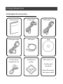
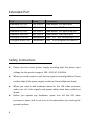
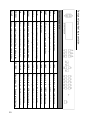
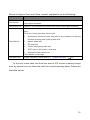
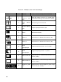
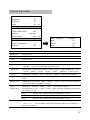
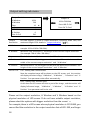
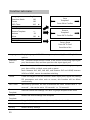
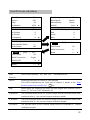
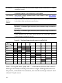
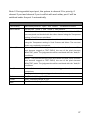
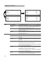
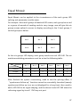
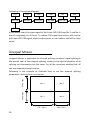
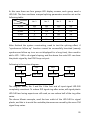
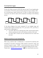
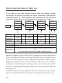
LED Video processor User manual △ Before using this LED Video processor, ! please read the instruction carefully and preserved for reference in the future. MAGNIMAGE LED-540 Statements Without the written permission, any unit or individual could not copy, reproduction or translate the book or part of it. Also could not transmit it in any form or any way(electronic, mechanical, photocopying, record or other way) for any business and profitable purpose. The product specifications and information mentioned in this manual is just for reference, will not give prior notice if there is any updated. Unless there is a special agreement, it is just used as guidelines. All the statements or information in this manual shall not constitute any form of guarantee. Directory BRIEFS ················································································································· 3 TRADEMARK CREDIT ·································································································· 3 ABOUT SOFTWARE ···································································································· 3 FEATURES ················································································································ 4 USING DIRECTIONS ····························································································· 5 INCLUDED ACCESSORIES ····························································································· 5 EXTENDED PORT ······································································································· 6 SAFETY INSTRUCTIONS ······························································································· 6 FUNCTION INTRODUCTION ················································································· 8 BRIEF ····················································································································· 8 REAR PANEL GRAPHICAL REPRESENTATION ······································································ 9 FRONT PANEL GRAPHICAL REPRESENTATION ·································································· 10 TECHNICAL SPECIFICATION ························································································ 11 USING THE MENUS ··························································································· 12 NON-MENU STATE INTRODUCTION·············································································· 12 MAIN MENU INTRODUCTION ····················································································· 15 Main menu ····································································································· 16 Picture sub menu ···························································································· 17 Output setting sub menu················································································ 18 Function sub menu ························································································· 20 Video Crop sub Menu ····················································································· 22 Zoom sub Menu······························································································ 24 Dual Pictures sub Menu·················································································· 25 Mosaic sub Menu ··························································································· 30 Shortcuts menu ······························································································ 31 USING MOSAIC ································································································· 36 MOSAIC SUMMARIZE ······························································································· 36 EQUAL MOSAIC ······································································································ 37 UNEQUAL MOSAIC ·································································································· 38 MULTI MACHINE CONNECTION ········································································· 40 SUMMARIZE ·········································································································· 40 CONNECTION TYPE ·································································································· 41 1 MULTI MACHINE LOAD TEMPLATE ··············································································· 41 MULTI-MACHINE FADE IN FADE OUT ············································································ 42 INPUT SIGNAL HOT BACKUP ·············································································· 43 FAQ ··················································································································· 45 MODEL INTRODUCTION ···················································································· 47 WARRANTY ······································································································· 47 GRAPHIC CATALOGUE: FORM1:STATE ICONS AND MEANINGS................................................................ 14 FORM2:DUAL PICTURES INPUT SOURCE CONFLICT LIST ...................................... 26 2 Briefs Thanks for your purchasing our LED Video processor. Do hope you can enjoy the experience of the product performance. The design of the LED video processor conforms to international and industry standards. but if with improper operation, there will be a personal injury and property damage . In order to avoid the dangerous, please obey the relevant instructions when you install and operate the product. Trademark credit VGA and XGA are the trademarks of IBM. VESA is a Video Electronics Standards Association's trademark. HDMI、HDMI mark and High-Definition Multimedia Interface are all from HDMI Licensing LLC. Even if not specified company or product trademarks, trademark has been fully recognized. About software Do not change, decompile, counter-assembly, decryption or reverse engineering the software installed in the product, these acts are illegal. 3 Features Support ultra-high output resolution and line frequency resolution. To switch the Stand-alone signal input channel rapidly. Many machines' connection to achieve the function of switch and the prompt switch between multiple signals input channel. Picture and text overlay, cutout composite function, convenience to achieve the effect of the captions superposed and image compound. The multi-machine prompt restore function of working mould is Input hot backup function, allows you to be no longer embarrassed in convenience for you to switch rapidly in a variety of applications. case of sudden loss of the input signal. 4 Using directions Included Accessories Using manual Power line CVBS cable ╳ 2 DVI signal cable USB cable Disk 3.5 mm Stereo Certificate of M3 screws ╳ 4 headphone line quality Sending card stud bolts 4pin2.54 sending card power cable 5 Extended Port Port Model Explanation Extended DVI Port LED-540CD Add another DVI input port Extended HDMI Port LED-540CH Add another HDMI input port Extended SDI Port LED-540CS Add another SDI input/loop port Extended VGA Port LED-540CV Add another VGA input port Configure YUV Port Customized AV2、AV3、AV4 configured to YUV Configure Audio Out Customized AV3、AV4 configured to Audio LR Safety instructions Please use the correct power supply according that the power input voltage for this product range is 100~240V AC, 50/60Hz. When you need connect or pull out any signal or bound guideline. Please confirm that all the power supply cords have been pulled out ahead. When you need to add hardware device for the LED video processor, make sure all of the signals and power cables have been pulled out ahead. Before you operate any hardware, please turn off the LED video processor's power, and to set you on the electrostatic by touching the ground surfaces. 6 Please use the processor in clean, dry and ventilated environment, not use it in the high temperature, humidity environment. The product is the electronic product; please stay away from the fire, water and of which is inflammable and blast, dangerous. This product is with high pressure components, please don't open the case or maintain it by your own. As there is exceptional condition with smoke, ill-smelling, please turn off the switch at once and contact with the dealers. 7 Function introduction Brief LED-540 series products are the video processor developed for the large screen display system, adopted the top image processing chips , internal 12 bits processing, with clearer images and richer colors. Advanced alternate motion picture processing technology, to remove video motion tail or jagged, for the normal PAL/NTSC video, output image will be clearer, for the HD 1080i signal, output image details will be rich, full color and image quality is in the leading level. Advanced image scaling technology, can support tens of the resolution, single machine can maximum output 2304×1152, 2560×816, 1920×1200, 1536× 1536 resolution and maximum refresh frequency rate 120Hz, and can scale the input picture point by point according to the screen size. Intellectualized large size LED screen seamless splicing technique, the user just needs to have simple setting, they could realize that to send card picture splicing, can support 24576×24576 lattice LED screen; Unique synchronized moving technology, ensure high speed motion picture fluently without tail or derangements. Perfect video image input port, including 2 X VGA , 1 x DVI (can be extended for two input in unison), 1×HDMI 、1×YUV(optional) and 4 x video (PAL/NTSC), 1×SDI(optional), support all HD signal input, can be connected with various audio and video equipment. Support the seamless switch between different input signal sources and picture in picture function. The whole unit is with pure hardware framework, steady and reliable. 8 VGA1~VGA2 AV1~AV4 DVI input port(DVI-D) 2 way VGA input ports 4 way CVBS input ports DVI Loop VGA DVI1~DVI2 DVI loop from input DVI port VGA output port 2 way DVI output ports(DVI-D) HDMI Audio input port SDI digital audio input port HDMI digital audio input port output port Expand SDI Audio input port Optional Audio input/output port SDI Out Video output ports Rear panel graphical representation DVI HDMI input port video input ports HDMI Expand input port E.M. Audio output port 9 Front panel graphical representation DOWN UP LEFT MENU MODE AUTO OK PART CROP PIP Menu select/operational key, the right key Menu select/operational key, the down key Menu select/operational key, the up key Menu select/operational key, the left key Main menu key, or return key in the menu Exhale template loading shortcut menu Auto adjust display position of input image Confirm key LED part or full screen switch hotkey Input intercepting function hotkey Picture in picture function hotkey 10 / E.M. 9 / HDMI 8 / DVI 7 / VGA2 6 / VGA1 5 / FADE 4 / AV4 3 / AV3 2 / AV2 1 / AV1 Numeric key 10,Expand select button Numeric key 9,HDMI select button Numeric key 8,DVI select button Numeric key 7,VGA2 select button Numeric key 6,VGA1 select button Numeric key5, fad in & out hotkey Numeric key4, CVBS4 select button Numeric key3, CVBS3 select button Numeric key2, CVBS2 select button Numeric key1, CVBS1 select button Buttons introduction RIGHT 10 Technical Specification Input indicators Port AV Number 4 Resolution PAL/NTSC VGA 2 VESA standard DVI 1+1(inherent 1 way,scalable 1way) VESA standard(support 1080i) HDMI 1 EIA/CEA-861, HDMI-1.3 SDI 1(E.M.) 480i、576i、720p、1080i/p(3G SDI) Output indicators Port Number 1 Resolution VGA 1 DVI 2 1024×768/60Hz/75Hz/85Hz/100Hz/120Hz 1280×1024/60Hz 1440×900/60Hz 1600×1200/60Hz 1600×1200/60Hz – Reduced 1680×1050/60Hz 1920×1080/60Hz/50Hz 2560×816/60Hz 2048×640/60Hz 1920×1200/60Hz 2304×1152/60Hz DVI input looping out in accordance with DVI input, not to support HDCP looping out 2048×1152/60Hz 1024×1280/60Hz 1536×1536/60Hz SDI input looping out 1 480i、576i、720p、1080i/p(3G SDI) Complete machine specification Input power supply Power consumption 100~240VAC,50/60Hz 20W Working temperature 0~45℃ Overall dimensions (21 + 441 + 21)mm ╳ (282 + 16)mm ╳ (45 + 6)mm Weight 3.7 Kg 11 Using the Menus Using the menu system can set to this machine convenient and intuitive to meet the demands of user. LED-540 using a highlight and high contrast LCD screen to display the whole user menu. When the user does not operate or operate in overtime, the LCD screen will display a non-menu state. If you use the buttons on the front panel to set the machine, the LCD screen will display the menu according to user actions for the user to have prompt and better, more straightforward operations. We will introduce the LED -540 menu system combing the LCD display and the front panel buttons. Non-menu state introduction Turn on the power supply of LED-540, in the process of the system startup, the LCD front panel would display the start interface on the left screen, when the start completed, there will show the machine’s current state on the screen as the following figure shows: 12 Above the figure, there are 4 lines content, explanation as the following: Lines The first line The second line Details Channel 1 (main channel, is also default channel) port name and current input signal resolution. Channel 2 (vice-channel) port name and current input signal resolution. State prompt area, by several icons to show the machine current working state. There are 6 icons areas from left to right: 1、 Synchronism follow-up state area(valid in the condition of splicing function opening state) Splicing state area The third line 2、 Mosaic status area 3、 PIP state area 4、 Picture intercepting state area 5、 PART(part or full screen)state area 6、 Brightness grade status area Check details in next page. The fourth line Output resolution, check details in “Output indicators”[ 11] In the non-menu state, the third line area of LCD screen is status prompt area, by several icons to show the machine current working status. Please see the table below: 13 Form1:State icons and meanings Icons Area Name Hint(shortcut key in the bracket) Synchronism 1 follow-up state area 2 2 splicing state Unequal splicing state Synchronism follow-up is also started successfully Equal splicing function is Enable Unequal splicing function is open 3 PIP off PIP function off(PIP) 3 PIP on [1] PIP function on,channel 1 is on the top(PIP) 3 PIP on [2] PIP function on,channel 2 is on the top(PIP) 4 4 Image intercepting off Image intercepting on 5 PART function off 5 PART function on 6 14 Equal When the splicing function is in opening state, Image intercepting function turnoff(CROP) Image intercepting function on(CROP) PART function off,cutdown image shown on the monitor(PART) PART function on,full screen image shown on the monitor(PART) Brightness grade Digital presents current brightness grade, range icon from 0~100(UP、DOWN) Main menu introduction The main menu will show the symbols listed in the table below, please check its specific meaning in the table below: Symbols Explanation >> Press“RIGHT”or“OK”to enter the detail setting page, or operate that directly. ▼ The next page is after this page, press“DOWN”button in the last item of this page to enter the next page ▲ Before this page is the previous page, press the first project“UP”to enter the previous page. In the main MENU, the user can use the "MENU", "UP", "DOWN", "LEFT", "RIGHT", "OK" the six buttons to select and adjust the each item. Its operation is fixed pattern, please check the following table: Operation Button Open the main menu Press“MENU” in the un-menu state Select the each item Adjust the parameters Enter the next level menu Performs some specific functions Back to the higher level menu Confirm operation Press“UP”or“DOWN” , When there is“▼”or“▲”symbol on the right of the item ,there will be paging action. When there is digital parameter or option on the right of the item, please press “LEFT” or“RIGHT”. When there is“>>”on the right of item, press“RIGHT”or“OK” When there is“>>”on the right of item, press“RIGHT”or“OK” Press“MENU” When the reset operation, to avoid the incorrect operation, need to use the ”OK” button to confirm operation 15 Main menu In the MENU state, press“MENU”button, the MENU system will enter the main MENU state, the LCD screen will show the details as below: Picture >> Output Setting >> Function >> Video Crop >> ▼ Zoom >> ▲ Dual Pictures >> Mosaic >> The main menu has seven sub menu items divided into two pages and display separately. Press the“UP”or“DOWN”keys to choose the above listed seven sub MENU headings, after selected, to press“OK”or“RIGHT”button to enter the selected item, and press“MENU”button to return. 16 Picture sub menu Picture Mode Normal Brightness 50 Contrast 50 Color 50 ▼ 12 ▲ Sharpness 3DNR /VGA Flicker Scheme Off Normal DVI Enhance Off ▼ Black Stretch Off ▲ Color Temperature Gamma Color Tempture Normal Red 50 >> Green 50 Off Blue 50 Picture MOde Divided into “Normal” 、“Soft”、“Vivid”、“User” the four options. Brightness Range 0~100. Contrast Range 0~100. Color Range 0~100. Sharpness Range 0~24. 3DNR This function is valid when channel 1 is not VGA, divided into“Off” “Adaptive” 、 、 “Low” 、 “Medium” 、“High”these five kinds of denoise mode. VGA Flicker This function is valid when channel 1 port is VGA1 or VGA2, divided into“Off” 、 “Level0”、“Level1”、“Level2”、“Level3”、“Level4” 、 “Adaptive” the six modes. Scheme Divided into“Normal”、“Vivid”、“Theatre”、 “Game” 、“Sport”the five modes. DVI Enhance In the state of DVI input, the function can greatly improve the output image color and clarity Black Stretch Valid in the Picture mode to“Vivid” 、 “Theatre”、 “Game” 、 “Sport”, increases the black areas of the image to strengthen contrast. Color Temperature Divided into “Normal”、“Warm”、“Cool”、“User”the four options. Only when select“User”, “Red”、 “Green”、 “Blue”the three regulations is effect and the range is 0 to 100. Red Gamma Range 0~100,Valid in the color temperature is“user”. Green Range 0~100,Valid in the color temperature is“user”. Blue Range 0~100,Valid in the color temperature is“user”. Control the output Gamma value of video processor, divided into“Off” 、 “2.0”、 “2.2” 、 “2.8” 、 “- 1.1”、 “- 1.2”and“MIG”seven options, including“MIG”for our company’s Gamma curve values. 17 Output setting sub menu Output Resolution >> H Window 1024 V Window 768 Step Output To 1024×768 60Hz 16 ▼ 0 ▲ Press L&R To Sel Press OK To Conf H Position V Position 0 Part Or Full Full Output LED-540 support 19 kinds of output Resolution, maximum width 2560, and Resolution maximum height 1536. details in“output indicators”[ H Window Minimum is 64, maximum is“the width of the current output resolution”(for 11]。 example: 1024 of 1024×768 60Hz). V Window Minimum is 48, maximum is“the height of the current output resolution” Step The default value is 16, also can set to be 128 or 1. H Position Minimum value is -16; the biggest can be set to the differentials between“the (for example: 768 of 1024×768 60Hz). width of the current output resolution”and“H Window”. V Position Minimum value is -16; the biggest can be set to the differentials between“the height of the current output resolution”and“V Window”. Part Or Full Full:namely PART function shut. Now the complete image will be shown on the LED screen, and the monitor will display shrunken image,“H Window”“ , V Window”, “H Position”and “V Position”four parameters take effect automatically. Part:namely PART function open, At this time the LED screen will show a part of the image , and the monitor will display full screen image, “H Window”,“V Window”, “H Position”and “V Position”four parameters will to be void. Please set the output resolution, H Window and V Window based on the physical resolution of LED screen. If do not have suitable output resolution, please select the options with bigger resolution than the screen’s. For example, there is a LED screen whose physical resolution is 1152╳960, you cannot find the resolution in the output resolution lists of LED-540, and larger 18 and nearest resolution is“1280╳1024 60Hz”, in such circumstances, please set the output resolution to be“1280╳1024 60Hz”. In addition, still need to set the H Window to be the practical width of the LED screen, 1152. And the V Window should be the practical vertical height, 960. Note: please use the bigger than 60Hz refresh rate or greater height and width pixel output resolution judiciously, it is not sure that the back-end equipment can support this resolution. 19 Function sub menu Language English Seemless Switch Save Off Template 1 Freeze Off OSD Timer 30S ▼ Save Template >> ▲ Restore Template >> Volume Press OK to Confirm Restore Template 1 50 Mute Off ▼ Factory Reset >> ▲ Press OK To Confirm Factory Reset Press OK To Conf Press Mu to Rtn Language Display language of LED-540 menu system,have“中文”and“English”two options. Seemless Off:Seamless switch function closed, in the process of switching input signal Switch port, black screen first, and then open the new input signal port. On:Seamless switch function open, in the process of switching input signal port, there will be no black screen and no pause. Note: Between AV1, AV2, AV4 AV3, and between DVI and HDMI, between VGA1 and VGA2, cannot do seamless switching. Freeze Freeze all images of the two channels. Switch input ports, signal lost, setting PIP parameters and other such as occurs, this function will be failure automatically. OSD Timer Without any operation, the time of withdraw the menu. Default value is“30 seconds”, also can be set to“60 seconds”or“10 seconds”. Save Save the current user settings. Can save 10 groups template at the most. Template Restore Restore the before settings from template. Template Volume Range 0~100, Output volume adjustment, default value is 50. Mute Output volume mute. Factory Restore factory Settings. 20 LED-540 supports multi-machine to cascade, in the cascade condition, the machine provides a quick recovery multi-machine template function, namely shortcuts "MODE". In the cascade state, to press "MODE" button from any one of the front panel LED-540s, all LED-540s will enter into a unified restore template interface, and then use the ten numeric keys of the front panel, can rapid recovery multi-machine template. It will convenient for you to switch the working state rapidly in various application situations. For details, please check the Multi-machine connection introduction [ 29]。 21 Video Crop sub Menu Video Crop Off H start Setting >> V start 0 Coarse Width 1920 Height 1080 Step Reset >> 0 Video Crop Reset Press OK To Conf Menu To Cancel Video Crop Image cropping function for input signal“On”or“Off”. Default is Off. Setting H start:the minimum value is 0, the maximum value is the D-value of“input signal width”minus“64”. V start:the minimum value is 0, the maximum value is the D-value of“input signal height”minus“32”. Width:the minimum value is 64, the maximum value is the D-value of“input signal width”minus“H start”. Height:the minimum value is 32, the maximum value is the D-value of“input signal height”and“V start”. Step Divided into“Coarse”and“Fine”two patterns. Reset Reset the parameters within the current image intercepted submenu, after finishing the reset, display full image. Image intercepting function is only available in the state of“splicing function” and“zoom function”closed and the current input signal effective. When the image intercepting function is not available, enter the image intercepting sun menu from the main menu, the menu system will prompt the user to check the function conflict Settings. Image intercepting function is the function to intercept the input signal, and according the output Settings to output to the LED display. So the image intercepted window size and location, limits within the input signal window. The above graph parameter Settings are all mutual condition. 22 Additional remarks: input signal width, height and other information can be checked in the display of“current input signal resolution specifications”and in the state of“non-menu state”[ 12]. For example, input signal resolution specifications of 1 signal input channel is 1920 ╳ 1080 60Hz , then, the input signal width is 1920, the height is 1080, 60Hz is refresh frequency. 23 Zoom sub Menu Zoom Pan Off H Zoom Level 100% H Pan 0% V Zoom Level 100% V Pan 0% Pan >> ▼ Reset >> ▲ Zoom Reset Press OK To Conf MENU To Cancel Zoom Zoom function“On”and“Off”. The default is Off. H zoom level In percentage form to enlarge the image in horizontal direction, step length 5%, maximum is 1000%, and the minimum is 100%. V zoom level In percentage form to enlarge the image in vertical direction, step length of 5%, maximum is 1000% and the minimum is 100%. Pan H Pan:In percentage form to move the horizontal position of enlarged image, step length 1%, maximum is 100%. When set to 50%, the amplification window horizontal position is in the center of the horizontal position of original image. V Pan:In percentage form to move the vertical position of enlarged image, step length 1%, maximum is 100%. When set to 50%, the amplification window vertical position is in the center of the vertical position of original image. Reset Reset the current amplification function submenu parameter, after finishing reset, display full image. 24 Dual Pictures sub Menu Dual Pictures Off Text Overlay Off Source DVI Blend Mode Mode1 Above/Below Above Step 16 H Window 1024 ▼ V Window 768 ▲ H Position 0 V Position 0 Transparent 0 ▼ Text Overlay >> ▲ Fade In&Out Switch >> Auto Switch Off Reset Dual Text Overlay ▼ ▲ Red 0 Green 0 Blue 0 VGA1 <- 【OK】 -> DVI 0S Multi Connection >> Reset >> ▼ 0S Multi Connection Machine ID And Fade Period VGA1 <- 【OK】 -> DVI Fade Period And/Or Single 0 ▼ >> ▲ Dual Pictures function“On”and“Off”. The default is Off. Pictures Source Switching input port of channel 2 (vice channel). This will be restricted by the input port of channel 1, details in the“Dual pictures input source conflict list”[ Step 26]。 When adjust the following four items, the step length value selection can be set to "1", "16" and "128". Default for 16. H Window The horizontal width of the vice channel image, and the minimum value is 64, maximum value is“the current output resolution width”. V Window The vertical height of the vice channel image, and the minimum value is 48, maximum value is“the current output resolution height”. H Position The top-left corner of Vice channel image levels of coordinates in“output resolution window”. 25 V Position The top-left corner of Vice channel image vertical coordinates in“output resolution window”. Transparent The transparency of vice channel image, range is 0~3, when the value is 0, Text Overlay Text overlay, cutout synthesis menu, check details in the text overlay completely opaque, 3 the transparency is the highest. specification[ 27]. Fade Fade in and fade out, multi units combined switch menu entrance; see details In&Out in the fade in fade out function specification. Switch Auto Switch Off:automatic switching function closed. Window1:if channel1 signal is effective, then channel1 image is located in the top floor. Window2:if channel2 signal is effective, then channel2 image is located in the top floor. Signal:Between the two signal input channels, the input signal effective channel image is located in the top. Form2:Dual pictures input source conflict list CH1 AV1 AV2 AV3 AV4 VGA1 VGA2 DVI HDMI E.M. ╳ ╳ ╳ * * * * * * * * * * CH2 AV1 AV2 ╳ ╳ ╳ AV3 ╳ ╳ ╳ * * * * * AV4 ╳ ╳ ╳ * * * * * VGA1 ╳ VGA2 ╳ DVI ╳ HDMI ╳ E.M. Note 1: During the above graph with "*" combinations, because the channel 2 didn't go interlaced processing, there will be a slight shaking phenomenon in the picture, in this kind of circumstance, can consider exchange channel 1 and channel 2 input source. 26 Note 2: During switch input port, the system to channel 1 for priority, if channel 2 port and channel 1 port conflict with each other, port 2 will be switched under the port 1 automatically. Text Overlay Text Overlay Blend Mode Text overlay function“open”and“closed”. The default is closed. Divided into“mode 1”and“mode 2”two patterns. Mode 1:in this mode the text pixels are on top and not blended. The non-text pixels are blended with the other channel using the Transparent setting in Dual Pictures sub Menu. Mode 2:in this mode the text pixels are blended with the other channel using the Transparent setting in Dual Pictures sub Menu. The non-text pixels are completely transparent. Above/Below Above:The pixel that has any color value above the Red, Green and Blue level become tagged as TEXT PIXELS, the rest of the pixels become NON-TEXT pixels. The judgment should be combined with the "And/Or" conditions. Below:The pixel that has any color value below the Red, Green and Blue level become tagged as TEXT PIXELS, the rest of the pixels become NON-TEXT pixels. The judgment should be combined with the "And/Or" conditions. And/Or And : all three color must be used to trigger the above / below comparison Or:any color is enough to trigger the above / below comparison Red Red Threshold, Range: 0~255 Green Green Threshold, Range: 0~255 Blue Blue Threshold, Range: 0~255 27 Fade In&Out Switch Fade In&Out Switch “ VGA1 ╳ <- 【 OK 】 -> DVI ” , as shown in the left example, “【OK】”the left side shows the name of the input port of channel 1, channel 2 on the right shows the input port name; sample The cursor is on the left, the port name is VGA1, next to the“╳”that no valid signal under VGA1 input port; use the“OK”,“FADE”,“LEFT”or“RIGHT” key, between the two input ports Fade to switch; use the “ input port selection key ” could switch the under layer port to the appropriate port(Do not conflict with the top layer port, Please refer to Dual pictures input source conflict list [ 26]) Please note, if“╳”is shown beside the port name, there is no valid signal under the port, the actual display was a black screen. Fade Period The process of fade in fade out can experience for 0 second to 5 seconds. If set to 0 seconds, then switching process would be finished instantaneously. Multi Multi machine combined setting, combination switching function setting Connection machine, check details in the Multi-machine connection instruction[ Reset Press“RIGHT”or“OK”to reset the parameter in the fade in fade out function. 28 29] Multi-machine connection instruction Multi “ VGA2 <- 【OK】 -> ╳ DVI ”, as shown in the left example, the cursor is machine located in channel 2, port name is DVI, next to the“╳”that no valid signal Fade In&Out under DVI input port; when the cursor is located in the channel 2 (The Switch cursor on the right), use the“input port selection key”to switch the input port of channel 1. Use“LEFT”and“OK”button to make the channel 1 of current processor as the multi-connection processor’s output; use the“RIGHT”key to enable the channel 2 of current processor as the multi-connection processor’s output. Please refer“Multi-machine fade in fade out” [ Fade Period 42] Combination switch sets signal input port switching process can experience for 0 second to 5 seconds. If set to 0 seconds, then switching process would be finished instantaneously. Multi Connection Can be set to“single”and“multi machine connection”. Single:Not in the state of the multi-machine connection, that is, not in the state of the combination switching. Multi : the state of multi machine connection, namely combination switching state. Machine ID Range is 0~7,0 representing terminal machine, its previous level machine Numbers is 1, the level before the previous is 2, and so forth. Terminal, that is the video processor linking the LED sending card; Please refer to the“Multi-machine fade in fade out”[ Reset 42]. Press “RIGHT” or“ OK” to reset the parameter in the multi machine connection setting function. Note : Multi machine connection “Multi-machine fade in fade out”[ hardware setting, please check 42]. 29 Mosaic sub Menu Unequal Mosaic Mosaic Option Off Equal >> H Total Unequal >> V Total 640 H Start 0 ▼ 0 ▲ Equal Mosaic V Start Off Position 1 Width H Units 1 Height V Units 1 Step Equal 1536 768 320 16 Equal Mosaic The Equal Mosaic function“On”or“Off”, default is off. Position Choose the current video processor display position in the whole splicing image, range is 1~64. H Units The total number of the video processor in the horizontal direction, range is 1~8. V Units The total number of the video processor in the vertical direction, range is 1~8. Unequal Unequal Mosaic The Unequal Mosaic function“On”or“Off”, default is off. H Total The physical pixel points of the LED screen in horizontal direction. V Total The physical pixel points of the LED screen in vertical direction. H Start The level starting position of the display area that controlled by the current video processor. The LED screen top-left corner is viewed as the original point (horizontal starting point 0). V Start The vertical starting position of the display area that controlled by the current video processor. The LED screen top-left corner is viewed as the original point (vertical starting point 0). Width The pixel points that the display area of the current video processor shown in the horizontal direction. 30 Height The pixel points that the display area of the current video Setp The step length value that adjust the parameters of the processor shown in the vertical direction. unequal splicing can be set to“1”“ , and”and“128”, The default is“16”. Shortcuts menu LED-540 sets up total nine input shortcuts and six function shortcut keys. Input shortcuts are:“AV1”,“AV2”,“AV3”,“AV4”,“VGA1”,“VGA2”, “DVI” , “HDMI”and“E.M.”respectively; Function shortcuts are:“PIP” “CROP” , , “PART”,“AUTO”,“MODE”and“FADE”. All the name of the keys and its position of the machine, please refer to the "Front panel graphical representation" [ 10]。 Note: Unless specifically mentioned otherwise, all shortcut keys must be in “non-menu state”under to be effective. Input shortcuts In the non-menu state, press any input shortcuts, no.1 signal input channel port will switch directly to the input port which is corresponding with the input shortcuts. Moments later, the menu system will show the input channel state, including port name, whether the input signal is effective or not, also will show signal resolution specifications in effective case. About this content, please refer to the "Non-menu state introduction" [ 12]。 Additional remarks: in "seamless switching” function open state, press any input shortcuts, the system will be preparation for signal and automatic switching in the next around 1 seconds time, the whole switching will delay about 1 second, at that time, the LED - 540 menu system will display waiting 31 for information, as below: Source Switching Please Wait . . . When the seamless switching completed, the menu system will be into "non-menu state" automatically [ 12]. If users need to switch Channel 2 signal input port, please enter“PIP submenu”, and adjust“input source”option. Function shortcuts PIP function shortcuts: The shortcuts only can be available in“seamless switching”function closed. If in the PIP open state,“seamless switching”function open, then PIP function will be forced to close. Icon Explanation PIP function closed, channel 1 signal display normally. PIP function open, channel 1 is on top, namely channel 1 display area covers channel 2 image. PIP function open, channel 2 is on top, namely channel 2 display area covers channel 2 image. CROP function shortcuts: CROP function, namely“image intercepting”function, is only available on the condition of“Splicing function”and“amplification function”closed, and the current input signal effective. If the image intercepting function is not available, "CROP" button will not be response. Icon Explanation CROP function closed. CROP function open. 32 PART function shortcuts: PART function, namely PART or full-screen display image fast switching function. In the state of LED display normally, PART function should be closed; When in the circumstance of the monitor to setup broadcast, can use PART function open, image full resolution display characteristics, to make the process convenient and fast. Icon Explanation PART function closed. LED screen display the complete program picture, the program picture is shrinking in the monitor. PART function open. LED screen display part program picture, the programs’ picture is full screen in the monitor. AUTO function shortcuts: In the“non-menu state”[ 12], press“AUTO”button, the menu system will display the following tips: Auto Adjusting Please Wait . . . At this moment, system is to adjust the display position of the image automatically, after this process completed, the menu system returns to “non-menu state”[ 12]。 MODE function shortcuts: In the“non-menu state”[ 12], press "MODE" button, the menu system will enter the template loading shortcut menu state as below: 33 1 2 3 4 5 6 7 8 9 10 Num. Key To Load Templates Press a number key, then the corresponding template will be loaded into the system instantly, and the corresponding digital will also be displayed in highlight. For example: 1 2 3 4 5 6 7 8 9 10 Num. Key To Load Templates In the multi-machine connection state, any one unit LED-540 can be as the controller of “ MODE ” function. Ensure all the machines in the “non-menu state”[ 12], press the“MODE”shortcuts on any machine, all the machines will enter the template loading shortcut menu state, in this shortcut menu state, press any numeric key on any machine, then all the machine will load the corresponding template of their respective system, it is convenient for you to switch the working state in various application occasions rapidly. FADE function shortcuts: In the“non-menu state”[ 12], press“FADE”button, the menu system will enter the fade in fade out switching state as below: VGA1 <- 【OK】 -> Fade Period 34 DVI 0S Multi Connection >> Reset >> ▼ Tips: 1、In the shortcut menu, you can switch input port for the bottom layer, but it is not safe behavior, because in the absence of pre-monitoring situation, you can not accurately grasp the switching time. So please determine in advance which of the two inputs would get into the fade switch process. 2、In non-menu state, press“FADE”key to perform fade in & out operation, after the menu enter to fade menu state, in the first line by using“FADE” 、 “OK” 、 “LEFT”及“RIGHT”key to perform fade in and out process; High light characters is now display signal port, channel 1 input port name is on the left, channel 2 input port name is on the right. If there is“╳”beside the port name, means that there is no valid signal under the port. 3、The limitation of the fade in fade out function port, please check the Dual pictures input source conflict list. [ 26]。 35 Using Mosaic Mosaic summarize LED-540 single has two send card slots, two cards can convey the same image for the two LED display at the same time, also can use two cards cascading, and increase the load area for conveying HD image to a high resolution LED display. If the actual pixel of the LED display beyond of the sending cards loading ability, for this kind of circumstance, need to use more than one sending cards and use video processor splicing function to solve. Adopt processor splicing, namely can use multi machine combing to display the complete image, also can display independent image separately. Video processor LED-540 using“synchronous follow-up”technology, solved the difficult splicing problem: splicing image motion lacerate phenomenon, namely the phenomenon of the moving pictures dislocated in splicing crossing.“Synchronous follow-up”technology lets users easily use the LED video processor to realize the large LED screen splicing. “ Synchronous follow-up”function will open in the state of splicing function open, the menu system will give the current video synchronism state tips, about this part of the content, please refer to the“State icons and meanings”[ 14]. Video processor LED-540 provides two mosaic way, respectively is“equal”and “unequal”, the former setting is extremely simple, but for its application occasions has certain restriction, the latter settings is slightly complex, can deal with all splicing occasion. Following is the detailed LED-540 splicing function using introduction and the matters needing attention. 36 Equal Mosaic Equal Mosaic can be applied to the circumstances of the each group LED splicing unit parameters are the same. For example:there are 6 groups of identical LED screen, each group has a card or a group of cascade of sending cards to carry image, now will give this six groups screen spliced a screen to display according to the 3 level groups, 2 vertical groups as below: No. 1 No. 2 No. 3 No. 4 No. 5 No. 6 So this six groups LED display, each group needs one unit LED-540. The six machines switching parameters must be set as the following table: Processor Parameter No. 1 No. 2 No. 3 No. 4 No. 5 No. 6 Position 1 2 3 4 5 6 H Units 3 3 3 3 3 3 V Units 2 2 2 2 2 2 After finished the system constructing, need to test the splicing effect, if “synchronous follow-up”function cannot be successfully launched (namely synchronous follow-up icon are not displayed for a long time), then need to add a LED-540 to do signal shaping, and the above 6 sets LED-540 share the reforming signal by its self DVI loop out port. 37 Following is the system diagram: LED LED LED LED LED LED LED-540 LED-540 LED-540 LED-540 LED-540 LED-540 LED-540 In the above chart, the input signal of the 6 sets LED-540 from No. 1 and No. 6 are all completely on all fours. To reduce DVI signal loop series, will use the both two LED-540 signal plastic output ports, so can reduce half of the loop series. Unequal Mosaic Unequal Mosaic is applicable to all need splicing occasions, equal splicing is the special case of the unequal splicing, namely is the special situation of all splicing unit parameters are the same. For all the occasions besides that, all can use unequal joining function. Following is the example to illustrate how to set the unequal splicing parameters. Splicing form is as below: 384(Pixel) No. 2 288(Pixel) 38 No. 1 No. 3 No. 4 576(Pixel) 384(Pixel) In this case there are four groups LED display screens, each group need a LED-540. The four machines unequal splicing parameters must be set as the following table: Processor No. 1 No. 2 No. 3 No. 4 H Total 960 960 960 960 V Total 672 672 672 672 H Start 0 576 0 576 V Start 0 0 384 384 Width 576 384 576 384 Height 384 384 288 288 Parameter After finished the system constructing, need to test the splicing effect, if "synchronous follow-up" function cannot be successfully launched (namely synchronous follow-up icon are not displayed for a long time), then need to add a LED - 540 to do signal shaping, and the above four sets LED can share the plastic signal by itself DVI loop out port. Following is the system diagram: LED LED LED LED LED-540 LED-540 LED-540 LED-540 LED-540 The diagram above, No. 1 and No. 4 the four sets of input signal LED-540 completely consistent. To reduce DVI signal ring after series, will signal plastic LED-540 two losing exports are still used, so can reduce half of the ring after series. The above Mosaic example, used the two outlet of the LED-540 for signal plastic, and this is to avoid the unstable phenomenon caused by the more DVI signal loop series. 39 Note:The description for the pixel position of LED-540, is starting from 0, namely the top-left corner pixels horizontal and vertical positions are both for 0, increasing from left to right on the horizontal direction, on vertical direction increasing from top to bottom. Multi machine connection Summarize With the large area, HD display time arriving, the LED display area usually will beyond the sending card loaded area more, LED display project also is to realize by the way of using many screens and processors. However, with the increasing of the processors, let field control staff’s work also become complicated. For that, simplified site operation, LED-540 has multi-machine connection function. Multi-machine connection function is divided into the following two practical subfunction: A. all machines recover to a certain work mode quickly, namely “multi-machine loading template”. B. many units realize signal switching function, namely quick seamless switching during the different input signal, seamless, namely “multi-machine fade in fade out”. 40 Connection type On the left of the rear panel of LED-540, there are two 3.5 mm headset jacks, one marked as“TX”for the communications signals sent port; another is“RX” as a communication signal receiver port. In order to achieve multi machine connection, we need to connect all the machines according to the following picture. TX TX TX TX RX RX RX RX In the above diagram, the arrows represent 3.5 mm headset plug, and communication signals are always from“TX”port sent to“RX”port. This is a cyclic annular, its advantage is: A. any of LED-540 can be a starting point of the communication signal, namely operating terminal can be arbitrary machine of the ring. B. can easily add or remove one unit machine from the circular link structure. Multi machine load template When many machine state is established (i.e. connected the machines well according to the above mentioned“Multi machine connection mode”will machine connect), to press “MODE” function shortcuts in any one LED-540 front panel, all the machines will enter the template loading shortcut menu. Please return“MODE function shortcuts”[ 33] to check details instruction. 41 Multi-machine fade in fade out If you want to use multi machine fade in fade out function, besides connecting the machine according the above mentioned "multi-machine connection mode", it is also required to the connection for the rear panel signal line. Specific connection mode and setting please refer to below: LED No. 0 No. 1 No. 2 No.3 DVI IN DVI IN DVI IN DVI IN DVI Machine ID Multi Connection OUT DVI OUT DVI OUT DVI OUT Other Other Other Other P0 P1 P2 0 1 2 3 Multi Multi Multi Multi P3 P4 Ch. 1 Port P0 P1 P2 P3 Ch. 2 Port DVI DVI DVI P4 Auto Switch Dual Pictures Off On Main Menu->Dual Pictures->Fade In&Out Switch->Multi Connection Menu state Or Non-Menu State->FADE function hotkey->Multi Connection Above the diagram, with four LED-540 for example, the arrows represent the flow of DVI signals. Finished the setting of each machine according to above picture, the four machines formed a signal switching station. When need to display the image of the P1 port, just click the“OK”key on no.1 machine, similarly, if need to display P3 port image, then in no.3 machine click a "OK" button. The switching time for fade in fade out is from 0 second to 5 seconds for adjustment. In the final level of the video processor, channel 2 can be set to any one port which is not conflict with its own channel 1 port, such as the P4 port in the 42 figure above. If you need to display image from P4 port, only need to click the “RIGHT”key once on the machine 3. Note that , if the video processor, channel 2 is currently displayed image, through the“input port selection key”can be set to channel 1 input port, if there is no valid signal under the channel 1 port, the left will display a“╳”, if this time on the current video processor, press“OK”or“LEFT”key to perform the fade in and out switch, it will show a black screen. Please check details in“Multi-machine connection instruction”[ 29]. Input signal hot backup S ummarize Note that what the input signal warm backup is? What is the use of it? In simple terms, warm backup is that when the input signal missed, using spare input signal automatically and rapidly to replace the original input signal, maximum ensure output image uninterrupted. Hot backup is a powerful guarantee to the stability of the system, which makes the impact to be the lowest that made by signal input device failure. 43 How to use the hot backup? Enter the“PIP submenu”and select“automatic switching function”, you can set how to use LED-540 hot backup function here. Here are four options, for details please refer to the table below: Item Details Off Not to use the heat backup function Window1 Window2 If channel 1 signal is effective, then output channel 1 image, otherwise, the output channel 2 image. If channel 2 signal is effective, then output channel 2 image, otherwise, the output channel 1 image. In the case of two channels signal are invalid, the signal first effective of the two channels signal, then its image will be output, the behind signal does not affect the output image. Note that when you use the hot backup function, location and size of channel 1 or channel 2 output image should be set in advance according to actual use. Recommend using "picture 1 priority" option, set the backup sources to the channel 2. Hot backup is the operation based on the signal detection, when the signal source is unstable or lost moments, there will be instant black screen, but within the fastest time (around 0.2 seconds), backup channel image will be displayed, let picture interrupt time reduced to a minimum. 44 FAQ LED-540 provides abundant function for the customers, some functions use requires users to have quite a bit of professional knowledge. When you have problems, can try to timing machines, if cannot solve it according the following step, please contact with the local agent, or contact our service department directly. For your safety, do not attempt to repair the product by yourself. Phenomenon Equipment Check list without image, no display in the front panel. The front panel of the screen is information, Check the power cord Check the power switch Check whether properly connected the input displaying but Page [ 10] [ 9] [ 13] [ 13] [ 10] [ 15] [ 14] [ 9] signal and have switched to the corresponding no source (if no signal, the front panel LCD screen image output or output will display no signal, and the machine will image is not stable have no image output at the moment ) Check display terminals whether to support the output resolution and refresh rate of LED-540. Check if the brightness and contrast set too low. Check whether the user color temperature set check picture 1 and 2 input status, whether the too low. top picture showed a signal Try to reset the machine to be the factory setting by “factory reset” of the "function Settings" sub menu. Image display position deviation Enter“output Settings”submenu, adjust the “horizontal position”and“vertical position”, till the image display properly VGA or DVI port images showed abnormal Check whether the input signal resolution is accordance with VESA standard. 45 VGA Image displayed in not full screen Press the front panel "AUTO" button until the [ 8] [ 25] [ 18] [ 18] [ 10] image display correct (automatic adjustment, please use the full screen and not take black side signal) PIP display abnormal Check if it is reasonable that the item numerical of“horizontal width”and“vertical height”,“horizontal position”and“vertical position”of “PIP”submenu. Fade in fade out Check whether automatically switch function is closed function is invalid Whether the input signal of Picture 1 and picture 2 is effective. 46 Model introduction LED-540CX S SDI input/loop out D Expand external DVI input port V Expand external VGA input port H Expand external HDMI input port Warranty The whole unit warranty One year (from the buying date); If the invoice is lost, the 60 days after the production date will be the warranty start date for the product. The warranty provisions The machine soaking and collisions produced besmirch or surface scratches and other abnormal using causes of malfunction or damage; Demolition machine or modification, which is not to be agreed by our Using in the not specified used working conditions, resulting in fault or company; damage (such as high temperature, low voltage or unstable etc.); Force majeure (such as fire, earthquake, etc.) or natural disasters (like lightning, etc) caused the fault or damage; Beyond the product warranty. 47


![English-T series-NOVA-User manual-F [兼容模式]](http://vs1.manualzilla.com/store/data/005791006_1-acba31ea472695c25db426bea2198a0f-150x150.png)