1
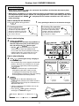
FILE NO. A04-005
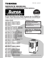
SERVICE MANUAL
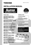
<OWNER'S MANUAL/INSTALLATION MANUAL>
R410A
Super Heat Recovery Multi System Air Conditioner
The indoor unit in Super Heat Recovery Multi System is common to one in Super Modular Multi System air conditioner.
Therefore refer to the service manuals for A03-011 separately issued.
Indoor Unit
<4-way Air Discharge Cassette Type>
MMU-AP0091H, AP0121H, AP0151H,
MMU-AP0181H, AP0241H, AP0271H,
MMU-AP0301H, AP0361H, AP0481H,
MMU-AP0561H
<2-way Air Discharge Cassette Type>
MMU-AP0071WH, AP0091WH, AP0121WH,
MMU-AP0151WH, AP0181WH, AP0241WH,
MMU-AP0271WH, AP0301WH
MMU-AP0481WH (CHINA market only)
<1-way Air Discharge Cassette Type>
MMU-AP0071YH, AP0091YH, AP0121YH,
MMU-AP0151SH, AP0181SH, AP0241SH
<Concealed Duct Standard Type>
MMD-AP0071BH, AP0091BH, AP0121BH,
MMD-AP0151BH, AP0181BH, AP0241BH,
MMD-AP0271BH, AP0301BH, AP0361BH,
MMD-AP0481BH, AP0561BH
<Concealed Duct High Static Pressure Type>
MMD-AP0181H, AP0241H, AP0271H,
MMD-AP0361H, AP0481H
<Under Ceiling Type>
MMC-AP0151H, AP0181H, AP0241H,
MMC-AP0271H, AP0361H, AP0481H
<High Wall Type>
MMK-AP0071H, AP0091H, AP0121H,
MMK-AP0151H, AP0181H, AP0241H
<Floor Standing Cabinet Type>
MML-AP0071H, AP0091H, AP0121H,
MML-AP0151H, AP0181H, AP0241H
<Floor Standing Concealed Type>
MML-AP0071BH, AP0091BH, AP0121BH,
MML-AP0151BH, AP0181BH, AP0241BH
<Floor Standing Type>
MMF-AP0151H, AP0181H, AP0241H,
MMF-AP0271H, AP0361H, AP0481H,
MMF-AP0561H
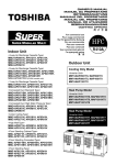
Outdoor Unit
Heat Recovery Model
<Inverter Unit>
MMY-MAP0801FT8, MAP1001FT8
MMY-MAP1201FT8
Flow Selector Unit (FS unit)
RBM-Y1121FE
RBM-Y1801FE
PRINTED IN JAPAN, OCT.2004 (TDOC)
ADOPTION OF NEW REFRIGERANT
This Air Conditioner is a new type which adopts a new
refrigerant HFC(R410A) instead of the conventional
refrigerant R22 in order to prevent destruction of the
ozone layer.
Thank you very much for purchasing TOSHIBA Air Conditioner.
Please read this manual carefully before using your Air Conditioner.
•Be sure to obtain the "Owner’s manual" and "Installation manual"
constructor (or dealer).
Request to constructor or dealer
Please clearly explain the contents of the Owner’s manual
and hand over it.
CONTENTS
Outdoor Unit
OWNER’S MANUAL
••••••••••••••••••••••••••••••••••••••••••••••••••••••••••••••••••••••••••••••••••••••••••••••••••••••••••••••••••••••••••••••••
PRECAUTIONS FOR SAFETY
••••••••••••••••••••••••••••••••••••••••••••••••••••••••••••••••••••••••••••••••••••••••••••••••••••••••••••••••••••••••••••••••••••••••
NAME OF EACH PART
••••••••••••••••••••••••••••••••••••••••••••••••••••••••••••••••••••••••••••••••••••••••••••••••••••••••••
PARTS NAME OF REMOTE CONTROLLER
•••••••••••••••••••••••••••••••••••••••••••••••••••••••••••••••••••••••••••••••••••••••••••••••••••••••••••••••••••••••••••••••••••••••••••••••
CORRECT USAGE
••••••••••••••••••••••••••••••••••••••••••••••••••••••••••••••••••••••••••••••••••••••••••••••••••••••••••••••••••••
ADJUSTMENT OF WIND DIRECTION
•••••••••••••••••••••••••••••••••••••••••••••••••••••••••••••••••••••••••••••••••••••••••••••••••••••••••••••••••••••••••••••••••••••••••••••
TIMER OPERATION
•••••••••••••••••••••••••••••••••••••••••••••••••••••••••••••••••••••••••••••••••••••••••••••••••••••••••••••••••••••••••••••••••••••••••••••••••••
INSTALLATION
•••••••••••••••••••••••••••••••••••••••••••••••••••••••••••••••••••••••••••••••••••••••••••••••••••••••••••••••••••••••••••••••••••••••••••••••••••
MAINTENANCE
•••••••••••••••••••••••••••••••••••••••••••••••••••••••••••••••••••••••••••••••••••••
AIR CONDITIONER OPERATIONS AND PERFORMANCE
••••••••••••••••••••••••••••••••••••••••••••••••••••••••••••••••••••••••••••••••••••••••••••••••••••••••••••••••••••••••••••••••••••••••••••••••
RE-INSTALLATION
•••••••••••••••••••••••••••••••••••••••••••••••••••••••••••••••••••••••••••••••••••••••••••••
WHEN THE FOLLOWING SYMPTOMS ARE FOUND
1
3
6
8
9
16
17
18
21
22
23
INSTALLATION MANUAL [ VOLUME-1 ]
•••••••••••••••••••••••••••••••••••••••••••••••••••••••••••••••••••••••••••••••••••••••••••••••••••••••••••••••••••••••••••••••••••••••••••
ACCESSORY PARTS
••••••••••••••••••••••••••••••••••••••••••••••••••••••••••••••••••••••••••••••••••••••••••••••••••••••••••••••••••••••••••••••••••••••••••••••
SAFETY CAUTION
••••••••••••••••••••••••••••••••••••••••••••••••••••••••••••••••••••••••••
1 INSTALLATION OF NEW REFRIGERANT AIR CONDITIONER
••••••••••••••••••••••••••••••••••••••••••••••••••••••••••••••••••••••••••••••••••••••••••••••••••••••••
2 SELECTION OF INSTALLATION PLACE
•••••••••••••••••••••••••••••••••••••••••••••••••••••••••••••••••••••••••••••••••••••••••••••••••••••••••••••••••••••
3 OUTDOOR UNIT CARRYING IN
••••••••••••••••••••••••••••••••••••••••••••••••••••••••••••••••••••••••••••••••••••••••••••••••••••••••••••••••
4 INSTALLATION OF OUTDOOR UNIT
••••••••••••••••••••••••••••••••••••••••••••••••••••••••••••••••••••••••••••••••••••••••••••••••••••••••••••••••••••••••••••••••
5 REFRIGERANT PIPING
25
25
27
28
29
30
32
INSTALLATION MANUAL [ VOLUME-2 ]
6
7
8
9
ELECTRIC WIRING
ADDRESS SETUP
TEST OPERATION
TROUBLESHOOTING
•••••••••••••••••••••••••••••••••••••••••••••••••••••••••••••••••••••••••••••••••••••••••••••••••••••••••••••••••••••••••••••••••••••••
•••••••••••••••••••••••••••••••••••••••••••••••••••••••••••••••••••••••••••••••••••••••••••••••••••••••••••••••••••••••••••••••••••••••••••
••••••••••••••••••••••••••••••••••••••••••••••••••••••••••••••••••••••••••••••••••••••••••••••••••••••••••••••••••••••••••••••••••••••••
•••••••••••••••••••••••••••••••••••••••••••••••••••••••••••••••••••••••••••••••••••••••••••••••••••••••••••••••••••••••••••••••••••
42
48
58
60
Flow Selector Unit
INSTALLATION MANUAL
••••••••••••••••••••••••••••••••••••••••••••••••••••••••••••••••••••••••••••••••••••••••••••••••••
Accessory parts and Parts to be procured locally
••••••••••••••••••••••••••••••••••••••••••••••••••••••••••••••••••••••••••••••••••••••••••••••••••••••••••••••••••••••••
1 PRECAUTIONS FOR SAFETY
••••••••••••••••••••••••••••••••••••••••••••••••••••••••••••••••••••••••••
2 INSTALLATION OF NEW REFRIGERANT AIR CONDITIONER
••••••••••••••••••••••••••••••••••••••••••••••••••••••••••••••••••••••••••••••••••••••••••••••••••••••••••
3 SELECTION OF INSTALLATION PLACE
•••••••••••••••••••••••••••••••••••••••••••••••••••••••••••••••••••••••••••••••••••••••••••••••••••
4 INSTALLATION OF FLOW SELECTOR UNIT
••••••••••••••••••••••••••••••••••••••••••••••••••••••••••••••••••••••••••••••••••••••••••••••••••••••••••••••••••••••••••••••••
5 REFRIGERANT PIPING
••••••••••••••••••••••••••••••••••••••••••••••••••••••••••••••••••••••••••••••••••••••••••••••••••••••••••••••••••••••••••••••••••••••••
6 ELECTRIC WORK
62
62
64
65
66
68
71
Outdoor Unit / OWNER'S MANUAL
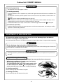
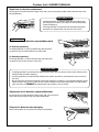
PRECAUTIONS FOR SAFETY
WARNING
Warning on installation
Be sure to leave the installation work to the dealer or a store
specializing.
The exclusive knowledge and technology are required for installation work.
Do not perform installation by yourself. If an incomplete installation is performed,
a fire, electric shock, injury, or water leakage may be caused.
Be sure to use the products sold separately which are specified by us.
For the products sold separately, be sure to use those specified by us. Otherwise,
a fire, electric shock, or water leakage may be caused. For installation work, leave
it to special engineer.
When installing the units in a small room, take measures so that the
refrigerant will not exceed the critical concentration if it leaks.
CAUTION
Related to countermeasures against the critical concentration, perform the installation work upon consultation with the dealer. If the refrigerant leaks and exceeds the critical concentration, oxygen deficiency
may be caused.
Check whether earthing work is performed correctly.
A grounding is necessary. If the earthing work is incompletely, an electric shock may be caused.
(For details, conform to the local regulation in each area.)
Warning on use
Do not expose your body directly in cool air for a long time, or do
not cool you excessively.
It causes the worse of physical condition or trouble on health.
Never insert a finger or bar into the air inlet port or air outlet port of air.
Since the fan rotates in high speed inside of the unit, an injury may be caused.
When a trouble (burnt smell, etc.) is felt, stop the operation, turn off
the power switch, and contact the dealer who you have purchased
the air conditioner.
If keeping operation as the air conditioner is defective, a fire, electric shock, or
trouble may be caused.
Do not use “Super HRM” for other than personal usage where the
ambient temperature may go down below –5°C.
For example, OA equipment/Electric device/Food/Animals and plants/Art object.
Warning on moving/repair
Never modify the air conditioner.
A fire or electric shock may be caused.
For repair, leave it to the dealer which you have purchased the air
conditioner.
If an incomplete repair is performed, a fire or electric shock may be caused.
When moving or re-installing the air conditioner, contact the dealer
which you have purchased the air conditioner or the special engineer.
If an incomplete installation is performed, a fire, electric shock, injury, or water
leakage may be caused.
1
CAUTION
Caution on installation
Check the drain pipes are installed so that they can drain water
securely.
If the piping is incomplete, water leakage occurs resulted in moisture on
furniture.
Check the earth leakage breaker is attached.
It is necessary to attach an earth leakage breaker. Otherwise, it causes an
electric shock.
Check the air conditioner is installed at a place where flammable
gas will not leak.
If gas leaks and accumulates in the unit surroundings, an outbreak of fire may
be caused.
Check the outdoor unit is fixed on the base.
If it is not fixed securely on the base, an accident such as falling may be
caused.
Check fixing method
Do not clean the air conditioner with water.
An electric shock may be caused.
Do not put the combustible devices at a place where air from the
air conditioner flows directly.
Imperfect combustion of the combustible devices may be caused.
Diligently ventilate the room when operating the air conditioner
with the combustible devices.
If ventilation is incomplete, shortage of oxygen may be caused.
Check the installation plate, etc. is not damaged by use for a long
time.
If leaving them damaged, the unit may fall resulted in injury, etc.
Do not put plants and animals at a place where air from the air
conditioner flows directly.
Cause to affect on plants and animals may generate.
Do not put flammable spray, etc. near the air conditioner, or do not
spray directly on the air conditioner.
A fire may be caused.
Do not put vessels including water such as a vase on the unit.
Moisture floods in the unit, the electric isolation deteriorates, and an electric
shock may be caused.
Do not handle the switches with wet hands.
An electric shock may be caused.
2
ENGLISH
Outdoor Unit / OWNER'S MANUAL
Outdoor Unit / OWNER'S MANUAL
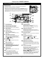
NAME OF EACH PART
Sold Separately Parts
Outdoor unit
Air inlet
They are provided at front,
rear, left, and right sides.
Power source hole
Refrigerant pipe connecting hole
Connecting valve is included
inside here.
Fixing leg
Indoor unit
[4-way Air Discharge Cassette Type]
Air filter
Removes dust and trash.
(Air filter is provided in the air grille.)
Air inlet grille
Air in the room is sucked from here.
Clip
The clip is to open/close the
air inlet grille.
[2-way Air Discharge Cassette Type]
Earth screw
It is included in the electric parts box.
Center panel
Air inlet
Air in the room is
sucked from here.
Air outlet/Air outlet flap
Select air blow direction in cooling or
heating operation each.
Air filter
Removes dust and trash.
(Air filter is provided in the center panel.)
[1-way Air Discharge Cassette Type]
MMD-AP0071YH to AP0121YH
MMD-AP0151SH to AP0241SH
Air outlet/Air outlet flap
Select air blow direction in
cooling or heating operation each.
Earth screw
It is included in the electric
parts box.
Simple wired remote controller
RBC-AS21E
Earth screw
It is included in the electric
parts box.
CODE No.
SET DATA
UNIT No.
SETTING TEST
R.C.
No.
UNIT
SET
CL
2-way discharge/3-way discharge
2-way discharge or 3-way discharge can be
selected according to the shape or
arrangement of the room.
For details, consult with the dealer which you
have purchased the air conditioner.
Earth screw
It is included in the electric parts box.
Air outlet/Air outlet flap
Select air blow direction in cooling
or heating operation each.
Air inlet grille
Air in the room is sucked from here.
Air inlet grille
Air in the room is sucked
from here.
Air filter
Removes dust and trash.
(Air filter is provided in the air inlet grille.)
Air filter
Removes dust and trash.
(Air filter is provided in the air inlet grille.)
3
Wireless remote controller kit
TCB-AX21E
RBC-AX21CE
RBC-AX22U(W)-E
Air outlet/Air outlet flap
Select air blow direction in cooling or
heating operation each.
Wired remote controller
RBC-AMT21E
Air outlet (Discharge)
Hot air is discharged when
cooling operation is performed.
Cold air is discharged when
heating operation is performed.
TEST
SETTING
˚C
Outdoor Unit / OWNER'S MANUAL
[Concealed Duct Type]
Air filter
Removes dust and trash.
(Air filter is provided in the air inlet grille.)
Earth screw
Earth screws are provided in
the electric parts box.
Air inlet
Air in the room is sucked from here.
Weekly timer
RBC-EXW21E
Air outlet flange
Discharge duct is connected.
SuMoTuWeTh Fr Sa
PROGRAM1
ERROR
PROGRAM2
PROGRAM3
WEEKLY TIMER
[Concealed Duct, High Static Pressure Type]
Air inlet
Suction duct is connected.
Drain pan
Earth screw
Earth screws are provided in the electric parts box.
[Under Ceiling Type]
Button
Button to open/close the
suction port
Air inlet port
The air in the room is sucked in
from this port.
Earth screw
Earth screws are provided in the
electric parts box.
Air filter
Removes dust or trash.
(Provided on the suction port.)
Air outlet/Air outlet flap
Change the direction of the air to
be discharged according to
cool/heat mode.
[High Wall Type]
Air inlet grille
Air in the room is sucked from here.
Air filter
Removes dust and trash.
(Air filter is provided in
the air inlet grille.)
Earth screw
Earth screws are provided
in the electric parts box.
Air outlet/Air outlet flap
Change the direction of the air to
be discharged according to
cool/heat mode.
4
Central remote controller
TCB-SC642TLE
Air outlet
Discharge duct is connected.
ZONE
ALL
ZONE
GROUP
CODE
No.
1234
SET DATA
SETTING
R.C.
UNIT No.
TEST
No.
GROUP
SELECT
ZONE
CL
SET
Outdoor Unit / OWNER'S MANUAL
[Floor Standing Cabinet Type]
Air outlet/Air outlet flap
Exchanges the air direction according to
cooling or heating time.
Earth screw
It is prepared in the electric parts box.
Air filter
Removes dirt or dust.
(It is included in the suction port.)
Air inlet port
Sucks air inside of the room from here.
[Floor Standing Concealed Type]
Air outlet port
Earth screw
It is prepared in the electric parts box.
Drain pan (With drain filter)
This accessory is installed at the local site.
Air inlet port
Sucks air inside of the room from here.
Air filter
Removes dirt or dust.
(It is included in the suction port.)
Front panel (Lower side)
[Floor Standing Type]
Fixing metal holder
Horizontal flap/Air outlet port
Exchanges the air direction according
to cooling or heating time.
Vertical flap
The air can be automatically discharged
rightward/leftward at stated periods.
Air inlet port
Sucks air inside of the room from here.
Drain pan
Water accumulated in the drain pan is
drained from here through the drain pipe.
Air filter
Removes dirt or dust.
Fixing metal holder (Right and left)
Earth screw
It is prepared in the electric parts box.
5
Outdoor Unit / OWNER'S MANUAL
PARTS NAME OF REMOTE CONTROLLER
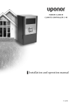
Display section
CODE No.
In the display example, all indicators are displayed for the explanation.
In reality only, the selected contents are indicated.
• When turning on the leak breaker at the first time, [SET DATA] flashes on
the display part of the remote controller. While this display is flashing, the
model is being automatically confirmed. Accordingly, wait for a while after
[SET DATA] display has disappeared, and then use the remote controller.
SET DATA
UNIT No.
SETTING TEST
8
17
4
7
1
SET DATA
UNIT No.
SETTING TEST
R.C.
No.
6
SET DATA display
12
Displayed during setup of the timer.
2
Operation mode select display
CHECK display
Displayed while the protective device works or
a trouble occurs.
4
5
6
14
Timer SETIN setup display
15
9
” is displayed, clean the air
Flap position display
(for 4-Way Air Discharge Cassette Type
and Under Ceiling Type model only)
16
17
Displayed during up/down movement of the
flap.
Set up temperature display
The selected set up temp. is displayed.
11
Operation ready display
No function display
Air volume select display
Mode select control display
Central control display
Displayed when using the remote controller together
with the central control remote controller, etc.
If Remote controller is prohibited at the
flashes when operating
centralcontrol side,
,
,
/
buttons and
the change is not accepted.
(The contents available to be set up on the remote
controller differ according to the central control
mode. For details, refer to Owner’s Manual of the
central control remote controller.)
SWING display
10
PRE-HEAT display
Displayed when pushing “Operation mode select”
button while the operation mode is fixed to heating
or cooling by the system manager of the air conditioner.
Displays flap position.
9
11
12
13
14
15
The selected air volume mode is displayed.
(HIGH)
(AUTO)
(MED.)
(LOW)
In the Concealed Duct High Static Pressure type
models, [HIGH] only is
displayed for the air speed.
Displayed during a test run.
8
10
Displayed if there is no function even if the button is
pushed.
Filter display
TEST run display
CL
Displayed when cooling or heating operation is
impossible because the outdoor temperature goes
out of the operable range.
Time of the timer is displayed.
(When a trouble occurs, the check code is
displayed.)
If “FILTER
filter.
7
13
Timer time display
When pushing the Timer SETIN button, the
display of the timer is selected in order of
[OFF]
→
[OFF] repeat OFF timer →
→ No display.
[ON]
Operation
section
Displayed when the heating operation starts or
defrost operation is carried out.
While this indication is displayed, the indoor fan
stops or the mode enters in LOW.
The selected operation mode is displayed.
3
Display
section
16
CODE No.
3
5
No.
UNIT
SET
1
2
R.C.
Remote controller sensor display
Displayed while the sensor of the remote
controller is used.
6
Outdoor Unit / OWNER'S MANUAL
Operation section
Push each button to select a desired operation.
This remote controller can operate the maximum 8 indoor units.
• The details of the operation needs to be set up once, afterward, the air conditioner can be used by pushing
button only.
1 7
8
2
3
9
4
UNIT
5
SET
10
CL
6
1
2
3
4
5
Timer set button
TIMER SET button is used when the timer is
set up.
Operation lamp
Lamp is lit during the operation. Lamp is off
when stopped.
Although it flashes when operating the protection device or abnormal time.
8
button
When the button is pushed, the operation
starts, and it stops by pushing the button
again.
When the operation has stopped, the operation
lamp and all the displays disappear.
Check button
The CHECK button is used for the check
operation. During normal operation, do not
use this button.
9
Fan button
FAN button is used when a fan which is sold on
the market or etc. is connected.
• If
is displayed on the remote controller
when pushing the FAN button, a fan is not
connected.
Operation select button
Selects desired operation mode.
10
Set up temperature button
Adjusts the room temperature.
Set the desired set temperature by pushing
or
.
Filter reset button
Resets (Erases) “FILTER
6
7
Air volume select button
Selects the desired air volume mode.
The Concealed Duct High Static Pressure type
models cannot be operated.
” display.
Wind direction and Swing
UNIT
:
Remote controller sensor
Usually the TEMP. sensor of the indoor unit senses
the temperature. The temperature on the surrounding of the remote controller can also be sensed.
For details, contact the dealer from which you have
purchased the air conditioner.
• In case that one remote controller controls the
multiple indoor units, the setup operation is
unavailable in group control.
If the multiple indoor units are operated by only
one remote controller, select the units when
the air direction is adjusted.
:
Set up the auto swing and angle of the flap.
• This function is not provided to Concealed
Duct Standard Type, High Static Pressure
Type, Floor standing Cabinet Type, or Floor
Standing Concealed Type.
7
Outdoor Unit / OWNER'S MANUAL
CORRECT USAGE
When you use the air conditioner for the first time or when you change the SET DATA value, follow the procedure below. From the next time, the operation displayed on the remote controller will start by pushing the
button only.
Preparation
Turn on the main power switch and/or the leakage breaker.
• When the power supply is turned on, a partition line is displayed on the display part of the remote controller.
* After the power supply is turned on, the remote controller does not accept an operation for approx. 1 minute,
but it is not a failure.
REQUIREMENT
• While using the air conditioner, operate it only with
button without turning off the main
power switch and the leak breaker.
• Do not turn off the leak breaker while the air conditioner is used.
• Turn on the leak breaker 12 hours or more before start of operation after the air conditioner has stopped
for a long time.
1
3
2
UNIT
SET
1
Push
4
CL
button.
The operation lamp goes on, and the operation starts.
2
3
Select an operation mode with the
button.
One push of the button, and the display
changes in the order shown on the right.
• “DRY” function is not provided to
Concealed Duct High Static Pressure Type.
AUTO
HEAT
DRY
COOL
FAN
(Dehumidity)
AUTO
HIGH
MED.
LOW
Select air volume with
button.
One push of the button, and the display changes in the order shown on the right.
• When air volume is “AUTO
”, air volume differs according to the temperature difference between
set temperature and room temperature.
• In DRY
mode, “AUTO
” is displayed and the air volume is LOW.
• In heating operation, if the room temperature is not heated sufficiently with volume “LOW
select “MED.
” or “HIGH
” operation.
” operation,
• The temperature which the temperature sensor detects is one near the air inlet of the indoor unit.
Therefore it slightly differs from the room temperature according to the installation status. The setup
value is a criterion of the room temperature. (Automatic air speed cannot be selected in FAN mode.)
• Air volume of function is not provided to “Concealed Duct High Static Pressure Type” but air speed
“HIGH
” only is displayed.
4
Determine the set up temperature by pushing the “TEMP.
Stop
Push
button.
The operation lamp goes off, and the operation stops.
8
” or “TEMP.
” button.
Outdoor Unit / OWNER'S MANUAL
REQUIREMENT
[In Cooling operation]
• The operation starts after approx. 1 minute.
[In Heating operation]
• In heating operation, the fan operation may continue for approx. 30 seconds after the air conditioner has
stopped.
• The indoor fan continues preheat operation for 3 to 5 minutes under stop condition, and then blows out
the hot air.
(
display on the remote controller display part goes on.)
• When temperature of the room has reached the setup temperature and the outdoor unit stops, the air
speed becomes super low and the air volume extremely is lessened.
is displayed.
• In the defrost mode, the fan stops so that cool air is not discharged and PRE-DEF
[In Automatic operation]
• Using the difference between the setup temperature and the room temperature, the heating or cooling
operation is automatically performed.
ADJUSTMENT OF WIND DIRECTION
To increase the cooling or heating effect, be sure to use the discharge flap in the different
directions in cooling or heating operation.
As the characteristics of the air, the cold air accumulates at lower side and hot air at upper side, respectively.
CAUTION
Set the discharge flap horizontally in cooling operation.
If cooling operation is performed with downward discharge, the surface of the discharge port or louver will
be wet with dew, and dewdrop may fall down.
REQUIREMENT
• If heating operation is performed with horizontal discharge, unevenness of temperature may increase in
the room.
4-way Air Discharge Cassette Type
• While the air conditioner stops, the discharge flap automatically directs downward.
• While the air conditioner is in ready status for heating,
the discharge flap directs upward.
The swinging operation starts after heating ready status
” is displayed on the
has been cleared, but “SWING
remote controller even if the status is ready to heating.
[In Cooling operation]
Use the discharge flap with horizontal set point.
[In Heating operation]
Use the discharge flap with downward set point.
9
Outdoor Unit / OWNER'S MANUAL
How to set up the air direction
Push
1
button.
Every pushing the button, the air direction changes.
In Heating operation
Set the air outlet flap downward.
If directing it upward, the hot air may not come to the foot.
Initial setup
In Cooling / Dry operation
Set the air outlet flap upward.
If directing it downward, the dew may fall on near the air discharge port or it drips.
Initial setup
How to start swinging
2
Push
button.
Set direction of the air outlet flap to the
lowest position and then push
button
again.
• [SWING
] is displayed and the air direction
automatically changes upward/downward.
In case when one remote controller controls
the multiple indoor units, each indoor unit can
be selected and its air direction can be set up.
4
SET
CL
1, 2, 3
How to stop swinging
3
UNIT
Push
button again during swinging
of the air outlet flap.
• The air outlet flap can be stopped at the
desired position. After then the air direction
can be again set up from the uppermost
position by pushing
button.
* While the air outlet flap is set downward in
cooling/drying operation, it does not stop.
If stopping the air outlet flap which directs
downward during swinging, it stops after
moving to the 3rd position from the top
position.
4
In FAN operation
In all modes
Series of
operation
Initial setup
Display when stopping the swing
Fan/Heat
operation
Cool/Dry
operation
UNIT
• To set up the air direction individually, push
UNIT button to display each indoor unit No.
in a group control. Then set up the air direction
to a displayed indoor unit.
• If there is no display, all the indoor units can be
operated collectively.
• Every pushing UNIT button, the display
exchanges as shown in the figure.
No display
Unit No. 1-1
Unit No. 1-4
10
Unit No. 1-2
Unit No. 1-3
Outdoor Unit / OWNER'S MANUAL
According to the shape or arrangement of the room, the cold air and hot air can be discharged for two directions or three directions. For details, contact the dealer.
INFORMATION
• If cooling operation is performed with downward discharge, dew may fall on surface of the cabinet or the
horizontal flap resulted in dripping.
• If heating operation is performed with horizontal discharge, unevenness of temperature may increase in
the room.
• Do not move the horizontal flap directly with hands; otherwise a trouble is caused. Select direction of the
horizontal flap using flap operation switch on the remote controller. The horizontal flap does not stop
immediately even if the switch is pushed. Adjusting the stop position, push the switch.
2-way Air Discharge Cassette Type
[In Cooling operation]
Use the air outlet flap with horizontal set point.
[In Heating operation]
Use the air outlet flap with downward set point.
Setup of air direction and swinging
1
2
3
Push
button during operation.
• [SWING
] is displayed and the air direction automatically changes upward/downward.
In case when one remote controller controls the multiple indoor units, each indoor unit can be selected
and its air direction can be set up.
Push
button again during swinging of the air
outlet flapp.
• The air outlet flap can be stopped at the desired
position.
UNIT
UNIT
• To set up the air direction individually, push UNIT
button to display each indoor unit No. in a group
control. Then set up the air direction to a displayed
indoor unit.
• If there is no display, all the indoor units can be operated collectively.
• Every pushing UNIT button, the display exchanges
as shown in the figure.
SET
1, 2
No display
Adjustment of air direction upward/downward
[In Cooling operation]
In cooling operation, use the air outlet flap with horizontal set point so that the
cold air diffuses in whole room.
[In Heating operation]
In heating operation, use the air outlet flap with downward set point so that
the hot air blows at the foot.
Adjustment of air direction rightward/leftward
To change the discharge direction to right or left side, set the vertical grille
inside of the air outlet flap to the desired direction.
Refer to description of “2-way Air Discharge Cassette Type”.
11
3
Unit No. 1-1
Unit No. 1-4
1-way Air Discharge Cassette Type
Setup of air direction and swinging
CL
Unit No. 1-2
Unit No. 1-3
Outdoor Unit / OWNER'S MANUAL
Under Ceiling Type
• While the air conditioner stops, the horizontal flap (Up/Down air direction adjustment plate)
automatically directs upward.
• While the air conditioner is in ready status for heating, the horizontal flap (Up/Down air direction adjustment plate) directs upward. The swinging operation starts after heating ready status
” is displayed on the remote controller even if the status is
has been cleared, but “SWING
ready to heating.
How to set up the air direction
Push
1
button during operation.
Every pushing the button, the air direction changes.
In Heating operation
In Cooling / Dry operation
Set the horizontal flap (Up/Down
air direction adjustment plate)
downward. If directing it upward,
the hot air may not come to the
foot come to the foot.
Set the horizontal flap (Up/Down
air direction adjustment plate)
upward. If directing it downward,
the dew may fall on near the air
air outlet port or it drips.
Initial setup
Initial setup
How to start swinging
2
Push
button.
Set direction of the horizontal flap (Up/Down air
direction adjustment plate) to the lowest position and then push
button again.
• [SWING
] is displayed and the air direction
automatically changes upward/downward.
In case when one remote controller controls the
multiple indoor units, each indoor unit can be
selected and its air direction can be set up.
How to stop swinging
3
4
Push
button again during swinging of
the horizontal flap.
• The horizontal flap can be stopped at the desired
position. After then the air direction can be again
set up from the uppermost position by pushing
button.
* While the horizontal flap is set downward in
cooling/drying operation, it does not stop.
If stopping the horizontal flap which directs
downward during swinging, it stops after moving
to the 3rd position from the top position.
UNIT
SET
CL
1, 2, 3
In FAN operation
4
In all modes
Series of
operation
Initial setup
Display when stopping the swing
UNIT
• To set up the air direction individually, push
UNIT button to display each indoor unit No. in
a group control. Then set up the air direction to a
displayed indoor unit.
• If there is no display, all the indoor units can be
operated collectively.
• Every pushing UNIT button, the display
exchanges as shown in the figure.
No display
Unit No. 1-1
Unit No. 1-4
Unit No. 1-2
Unit No. 1-3
12
Fan/Heat
operation
Cool/Dry
operation
Outdoor Unit / OWNER'S MANUAL
Right/Left air direction adjustment
To change the air outlet direction to right or left side, set the vertical flap inside of the horizontal flap to the
desired direction.
INFORMATION
• If cooling operation is performed with downward discharge,
dew may fall on surface of the cabinet or the horizontal flap
resulted in dripping.
• If heating operation is performed with horizontal discharge,
unevenness of temperature may increase in the room.
High Wall Type
Adjustment of air direction upward/downward
[In Cooling operation]
In cooling operation, use the horizontal flap with horizontal
set point so that the cold air diffuses in whole room.
[In Heating operation]
In heating operation, use the horizontal flap with downward
set point so that the hot air blows at the foot.
REQUIREMENT
• If cooling operation is performed with downward air outlet, dew may fall on surface of the cabinet or the
horizontal flap resulted in dripping.
• If heating operation is performed with horizontal air outlet, unevenness of temperature may increase in
the room.
• Do not move the horizontal flap directly with hands; otherwise a trouble is caused. Select direction of the
horizontal flap using
switch on the remote controller. The horizontal flap does not stop immediately even if the switch is pushed. Adjusting the stop position, push the switch.
Adjustment of air direction rightward/leftward
To change the air outlet direction to right or left side, set the vertical
flap inside of the horizontal flap to the desired direction.
Setup of air direction and swinging
Refer to description of “2-way Air Discharge Cassette Type”.
13
Outdoor Unit / OWNER'S MANUAL
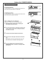
Floor Standing Cabinet Type
[In Cooling operation]
In cooling operation, use the air outlet flap with horizontal set
point so that the cold air diffuses in whole room.
[In Heating operation]
In heating operation, use the air outlet flap with downward set
point so that the hot air blows at the foot.
How to change the air outlet port
Change the air outlet port in the following procedure.
1
2
3
4
5
Take off two fixing screws of the air outlet port.
(The fixing screws are reused.)
Insert the hand into the air outlet port and push up it
a little, and then remove the air outlet port from the
claw hook at rear side.
Lift up the air outlet port upward and remove it.
Reverse the air outlet port and attach it to the main
unit.
Pay attention so that four claw hooks (two at rear and
lower sides each) are hooked at mounting position.
Be sure to tighten the air outlet port with the removed fixing screws so that the air outlet port does
not come off.
14
Outdoor Unit / OWNER'S MANUAL
Floor Standing Type
Adjustment of air direction upward/downward
[In Cooling operation]
In cooling operation, move the flap with hands and use it with horizontal air outlet
point so that the cold air diffuses in whole room.
[In Heating operation]
In heating operation, move the flap with hands and use the horizontal flap with
downward set point so that the hot air blows at the foot.
Adjustment of air direction rightward/leftward
[In case of using unsymmetrical air directions]
Lift up the vertical flap lightly, direct it toward the desired
direction, and lower it.
In this case, do not use the Swing function.
2
1
[In case of automatic swing]
1
In this case, do not use the
swing function.
Push
button during operation.
• [SWING
] is displayed and the air direction automatically changes rightward/
leftward.
In case when one remote controller controls
the multiple indoor units, each indoor unit
can be selected and its air direction can be
set up.
UNIT
2
3
Push
button again during swinging
of the vertical flap.
• The vertical flap can be stopped at the
desired position.
SET
CL
1, 2
Swing button UNIT
• To set up the air direction individually, push
UNIT button to display each indoor unit
No. in a group control. Then set up the air
direction to a displayed indoor unit.
• If there is no display, all the indoor units can
be operated collectively.
• Every pushing UNIT button, the display
exchanges as shown in the figure.
No display
3
Unit No. 1-1
Unit No. 1-4
Unit No. 1-2
Unit No. 1-3
INFORMATION
• If cooling operation is performed with downward air outlet, dew may fall on surface of the cabinet or the
horizontal flap resulted in dripping.
• If heating operation is performed with horizontal air outlet, unevenness of temperature may increase in
the room.
• Do not move the flap directly with hands during swing operation; otherwise a trouble is caused.
The vertical flap does not stop immediately even if the
button is pushed. Adjusting the stop
position, push the
button.
15
Outdoor Unit / OWNER'S MANUAL
TIMER OPERATION
A type of timer operation can be selected from the following three types.
OFF timer
: The operation stops when the time of timer has reached the set time.
Repeat OFF timer : Every time, the operation stops after the set time has passed.
ON timer
: The operation starts when the time of timer has reached the set time.
Timer operation
1
UNIT
2
SET
CL
34
1
Push TIMER SET button.
• The timer display (type) changes for every
push of the button.
• SET DATA and
display flashes.
OFF
OFF
ON
(OFF timer)
(Repeat OFF timer)
(ON timer)
No display
2
Push
to select “SET TIME”.
For every push of
button, the set time increases in the unit of 0.5 hr (30 minutes).
The maximum set time is 72.0 hr.
For every push of
button, the set time decreases in the unit of 0.5 hr (30 minutes).
The minimum set time is 0.5 hr.
3
Push SET button.
• SET DATA display disappears and
display goes on.
(When ON timer is activated, time is displayed, and after time of the timer has been up, displays other
than ON disappear.)
Cancel of timer operation
4
Push CL button.
• TIMER display disappears.
NOTICE
• When the operation stops after the timer reached the preset time, the Repeat OFF timer resumes the
operation by pushing
button and stops the operation after the time of the timer has reached
the set time.
16
Outdoor Unit / OWNER'S MANUAL
INSTALLATION
Installation location
WARNING
• Select a location for installation that will be able to safely bear the weight of the unit.
If the installation location is not strong enough to support the unit and the unit falls, injury could result.
CAUTION
• Do not install the unit in a location where combustible gases could conceivably leak.
Leaking gases that accumulate in the vicinity of the unit could be ignited by the unit.
REQUIREMENT
• A location that permits level installation of the unit
• A location that provides enough space to service the unit safely
• A location where water draining from the unit will not pose a problem
Avoid the following types of locations :
• Locations where salt is present in large amounts (seaside areas), or where sulfuric gases are present in
large amounts (hot springs areas)
(If the unit is to be used in such areas, special maintenance is necessary.)
• Locations that generate oils (including machine oils), steam, oily smoke, or corrosive gases
• Locations where organic solvents are used
• Locations in the vicinity of equipment that generates high frequency signals
• Locations where the outdoor unit will blow in the direction of a neighbor's window
• Locations where the noise of the outdoor unit will pose a problem
• Locations with poor air circulation
Electric wiring
WARNING
Check that earthing practice is correctly performed.
Grounding is necessary. If earthing practice is incomplete, an electric shock may be caused.
CAUTION
Check the circuit breaker is fitted.
Attaching the earth leakage breaker is necessary. Otherwise, an electric shock may be caused.
Make sure that correct capacity Fuses are used.
Using wire or copper wire may cause a fire or trouble.
For the power supply, use a circuit with rated voltage exclusive for air conditioner.
To disconnect the appliance from the main power supply.
This appliance must be connected to the main power supply by means of circuit breaker or a switch with a
contact separation of at least 3mm.
17
Outdoor Unit / OWNER'S MANUAL
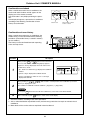
MAINTENANCE
Cleaning of air filter
• When [FILTER] is displayed on the remote controller, maintain the air filter.
• Clogging of air filter decreases cooling/heating effect.
CODE No.
SET DATA
UNIT No.
FILTER display
SETTING TEST
R.C.
No.
Notifies the time to clean the air filter.
UNIT
FILTER reset
SET
Push the FILTER switch after cleaning.
“FILTER” display disappears.
CL
WARNING
Be sure to turn off the main power switch prior to the maintenance.
• Please do not intend to do the daily maintenance and/or Air Filter cleaning by yourself.
Cleaning of the air filter and other parts of the air filter involves dangerous work in high places, so be
sure to have a service person do it. Do not attempt it yourself.
<Daily maintenance>
• For daily maintenance including Air Filter cleaning, make sure to ask the qualified service person particularly following models;
4-way Air Discharge Cassette Type
Concealed Duct Type
2-way Air Discharge Cassette Type
Concealed Duct, High Static Pressure Type
1-way Air Discharge Cassette Type
Under Ceiling Type
2-way Air Discharge
Cassette Type
4-way Air Discharge
Cassette Type
1-way Air Discharge
Cassette Type
Concealed Duct Type
Under Ceiling Type
Concealed Duct,
High Static Pressure Type
18
Outdoor Unit / OWNER'S MANUAL
High Wall Type
• Push the projection at the center of air filter. Clip is out.
• Undo the clip of air filter, pull the air filter downward while
pushing it toward the main unit side.
Push the air filter,
and pull it downward.
Floor Standing Cabinet Type
• Push down the upper part of the suction port a little,
and then pull toward you to remove it.
• Take out the air filter inside of the suction port.
Floor Standing Concealed Type
• Push down hook of the air filter on the front panel
(Lower side).
• Pull the air filter toward you to remove it.
Front panel
(Lower)
Air filter knob
Floor Standing Type
Removal / Attachment of air filter
• Pull the air filter toward you.
• To attach the air filter, insert it into the main body and push in it.
NOTE
• For cleaning of air filter, use a cleaner or brush clean. If stain is heavy,
it is effective to wash the air filter in tepid water mixed with neutral detergent.
• After washing, rinse it well, and dry it in the shade.
• Install again the air filter which has been cleaned.
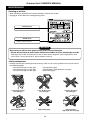
Cleaning of main unit / remote controller
CAUTION
• Wipe them with soft and dry cloth.
• A cloth dampened with cold water may be used on the indoor
unit if it is very dirty.
• Never use a damp cloth on the main unit and remote controller.
• Do not use a chemically-treated duster for wiping or leave such
materials on the unit for long. It may damage or fade the surface of the unit.
• Do not use benzine, thinner, polishing powder, or similar solvents for cleaning. These may cause the plastic surface to
crack or deform.
19
Thinner
Polishing Benzene
powder
Chemical
floor-cloth
Do not use.
Outdoor Unit / OWNER'S MANUAL
If you do not plan to use the unit for more than 1 month
(1) Operate the fan for 3 to 4 hours to dry inside the unit
• Operate “FAN” mode.
(2) Stop the air conditioner and turn off the main power switch
or the circuit breaker.
I will wipe soft
and dry cloth!
Checks before operation
(1) Check that the air filters are installed.
(2) Check that the air outlet or inlet is not blocked.
(3) Turn on the main power switch or the circuit breaker for the
main power supply to the air conditioner.
Use after drying
when it has not been
used for a long time!
NOTE
For Air conditioning system which is operated regularly, cleaning and maintenance of the indoor/outdoor
units are strongly recommended.
As a general rule, if an indoor unit is operated for about 8 hours daily, the indoor/outdoor units will need to
be cleaned at least once every 3-MONTH. This cleaning and maintenance shall be carried out by a
qualified person.
Failure to clean the indoor/outdoor units regularly will result in poor performance, icing, water leaking and
even compressor failure.
HINTS FOR ECONOMICAL OPERATION
Maintain room temperature at comfortable level
Clean air filters
The clogged air filter impairs the performance of the air conditioner.
Never open doors and windows more often than necessary
Gee, chilly
To keep cool or warm air in the room, never open doors and
windows more often than necessary.
Control
Window curtains
In cooling, close the curtains to avoid direct sunlight.
In heating, close the curtains to keep the heat in.
Clean, please.
Get uniform circulation of room air
Ple
ase
clo
se
Adjust the air flow direction for the even
circulation of room air.
Blows upward
Air flow adjustment
Cool and
dry air
Warm
air
Blows downward
20
Outdoor Unit / OWNER'S MANUAL
AIR CONDITIONER OPERATIONS AND PERFORMANCE
Check before operation
WARNING
• Check whether earth wire is disconnected or out of place.
• Check that air filter is installed to the indoor unit.
Heating capacity
Turn on the power switch
12 hours or more before
starting before operation.
• For heating, a heat pump system which sucks in outside heat air
and discharges it into the room is adopted.
If temperature of the outside air lowers, the heating capacity decreases.
• When temperature of the outside air is low, it is recommended to use other heating equipment together.
Defrost operation during heating operation
• If the outdoor unit has some frost during heating operation, the operation mode changes automatically to
defrost mode to increase the heating effect (for approx. 2 to 10 minutes).
• During defrost operation, fans of the indoor and the outdoor units stop.
Protection for 3 minutes
• The outdoor unit does not operate for approx. 3 minutes after air conditioner has been immediately restarted
after stop, or power switch has been turned on. This is to protect the system.
Main power failure
• If a power failure occurred during the operation, all operations stop.
• When restarting the operation, push ON/OFF button again.
Fan rotation of stopped unit
• While other indoor units operate, the fan on indoor units on “stand-by” rotates to protect the machine once
per approx. 1 hour for several minutes.
Protective device (High pressure switch)
The high pressure switch stops the air conditioner automatically when excessive load is applied to the air
conditioner.
If the protective device works, the operation lamp keeps lit but the operation stops.
When the protective device works, check characters “ ” in the remote controller display part flash.
The protective device may work in the following cases.
• When suction or discharge port of the outdoor unit closed.
• When strong wind blows continuously against discharge port of the outdoor unit.
• When dust or dirt is excessively adhered to air filter of the indoor unit.
• When discharge port of the indoor unit is blocked.
Cooling/heating operation of Heat Recovery Multi air conditioner
• When the outdoor temperature goes out of the operable range, cooling or heating operation may not be
performed in order to protect the equipment. In this case, “ ” goes on.
Characteristics of heating operation
• Hot air is not out immediately after the operation has started. After 3 to 5 minutes (differs according to room
or outside temperature) has passed and the indoor heat exchanger has been warmed up, hot air blows out.
• During operation, the outdoor unit may stop if outside temperature becomes high.
• When other outdoor unit performs heating operation while the fan is operating, the fan operation may be
stopped temporarily to prevent blowing of hot air.
Characteristics of cooling/heating simultaneous operation
• If the outdoor temperature drops during operation, the fan of the outdoor unit may stop.
21
Outdoor Unit / OWNER'S MANUAL
Air conditioner operating conditions
For proper performance, operate the air conditioner under the following temperature conditions:
Cooling
operation
Outdoor temperature
: –5°C to 43°C (Dry-bulb temp.)
Room temperature
: 21°C to 32°C (Dry-bulb temp.), 15°C to 24°C (Wet-bulb temp.)
CAUTION
Heating
operation
Room relative humidity – less than 80 %. If the air conditioner operates
in excess of this figure, the surface of the air conditioner may cause dewing.
Outdoor temperature
: –15°C to 21°C (Dry-bulb temp.), –15°C to 15.5°C (Wet-bulb temp.)
Room temperature
: 15°C to 28°C (Dry-bulb temp.)
• If air conditioner is used outside of the above conditions, safety protection may work.
* Do not use “Super HRM” for other than personal usage where the ambient temperature may go down below
–5°C. (For example, OA equipment/Electric device/Food/Animals and plants/Art object)
CAUTION
When outdoor temperature goes out of specified range, “
or ” mark is indicated on the Wired remote
controller display and required operation will stop.
“
& ” : When heating operation. “ ” : When cooling operation.
Notice :
• This indication is not failure.
• When outdoor temperature goes back to specified range, “ or ” disappear and start normal operation.
• Operation stops because concurrent operation can not be kept in the condition of out of specification for
Super HRM.
(Outdoor temp. (DB) < –5°C : Cooling, > 21°C : Heating)
RE-INSTALLATION
DANGER
Ask the dealer or an installation professional to re-install the air conditioner to a new place or
move it to another place and to observe the following items.
If the air conditioner is inappropriate installed by yourself, it may cause electric shock or fire.
Do not install the air conditioner in the following places
• Do not install the air conditioner in any place within 1 m from a TV, stereo, or radio set. If the unit is installed in
such place, noise transmitted from the air conditioner affects the operation of these appliances.
• Do not install the air conditioner near a high frequency appliance (sewing machine or massager for business
use, etc.), otherwise the air conditioner may malfunction.
• Do not install the air conditioner in a humid or oily place, or in a place where steam, soot, or corrosive gas is
generated.
• Do not install the air conditioner in a salty place such as seaside area.
• Do not install the air conditioner in a place where a great deal of machine oil is used.
• Do not install the air conditioner in a place where it is usually exposed to strong wind such as in seaside area or
on the roof or upper floor of a building.
• Do not install the air conditioner in a place where sulfureous gas generated such as in a spa.
• Do not install the air conditioner in a vessel or mobile crane.
Be careful with noise or vibrations
• Do not install the air conditioner in a place where noise by outdoor
unit or hot air from its air outlet annoys your neighbors.
• Install the air conditioner on a solid and stable foundation so that it
prevents transmission of resonating, operation noise and vibration.
• If one indoor unit is operating, some sound may be audible from
other indoor units that are not operating.
22
Outdoor Unit / OWNER'S MANUAL
WHEN THE FOLLOWING SYMPTOMS ARE FOUND
Check the points described below before asking repair servicing.
Symptom
Cause
• White misty cold air or
water is out.
• Sometimes, noise
“Pushu !” is heard.
• Fan of the outdoor unit stops automatically and performs defrost
operation.
• Solenoid valve works when defrost operation starts or finishes.
Indoor unit
• “Swish” sound is
heard sometimes.
• When the operation has started, during the operation, or immediately after the operation has stopped, a sound such as water flows
may be heard, and the operation sound may become larger for 2 or
3 minutes immediately after the operation has started. They are
flowing sound of refrigerant or draining sound of dehumidifier.
• This is sound generated when heat exchanger, etc. expand and
contract slightly due to change of temperature.
• Various smell such as one of wall, carpet, clothes, cigarette, or
cosmetics adhere to the air conditioner.
• Do not the outdoor temperature go out of the specified range?
• When the manager of the air conditioner has fixed the operation to
COOL or HEAT, and an operation contrary to the setup operation is
performed.
• When fan operation stopped to prevent discharge of hot air.
• Since refrigerant is flowed temporarily to prevent stay of oil or
refrigerant in the stand by indoor unit, sound of flowing refrigerant,
“Kyururu” or “Shaa” may be heard or white steam when other indoor
unit operates in HEAT mode, and cold air in COOL mode may be
blow-out.
• Sound is generated when the expansion valve operates when
power has been turned on.
It is not a failure.
Outdoor unit
• Slight “Pishi!” sound is
heard.
• Discharge air smells.
” indication is lit.
• “
• Sound or cool air is
output from the stand
by indoor unit.
• When power of the air
conditioner is turned
on, “Ticktock” sound is
heard.
Operates or stops automatically.
• Is the timer “ON” or “OFF”?
Does not operate.
•
•
•
•
•
•
t
Check again.
Silen
Air is not cooled or warmed sufficiently.
It’s strange.
Is it a power failure?
Is the power switch turned off?
Is the power fuse or breaker blown?
Has the protective device operated? (The operation lamp goes on.)
Is the timer “ON”? (The operation lamp goes on.)
Do not the outdoor temperature go out of the specified range?
•
•
•
•
•
Is the suction port or discharge port of the outdoor unit obstructed?
Are any door or window open?
Is the air filter clogged with dust?
Is discharge louver of the indoor unit set at appropriate position?
Is air selection set to “LOW” “MED”, and is the operation mode set
to “FAN”?
• Is the setup temp. the appropriate temperature?
• Do not the outdoor temperature go out of the specified range?
When the following symptoms are found, stop the operation immediately, turn off the power switch, and
contact the dealer which you have purchased the air conditioner.
• Activation of switch is unstable.
• The main power fuse often blows out, or circuit breaker is often activated.
• Foreign matters or water entered by mistake.
• When if activation cause of the protective device has been removed, the operation is not performed.
• Other unusual status occurred.
23
Outdoor Unit / OWNER'S MANUAL
Confirmation and check
When a trouble occurred in the air conditioner, the
check code and the indoor unit No. appear on the
display part of the remote controller.
The check code is only displayed during the operation.
If the display disappears, operate the air conditioner
according to the following “Confirmation of error
history” for confirmation.
CODE No.
UNIT No.
R.C.
Check code
No.
Indoor unit No. in which
an error occurred
Confirmation of error history
When a trouble occurred on the air conditioner, the
trouble history can be confirmed with the following
procedure. (The trouble history is stored in memory
up to 4 troubles.)
The history can be confirmed from both operating
status and stop status.
3
UNIT
SET
2
CL
1
Procedure
Description
When pushing SET and
buttons at the same time
for 4 seconds or more, the following display appears.
If [Service check] is displayed, the mode enters in the
trouble history mode.
1
• [01 : Order of trouble history] is displayed in CODE No.
window.
CODE No.
UNIT No.
R.C.
No.
• [Check code] is displayed in CHECK window.
• [Indoor unit address in which an error occurred] is
displayed in UNIT No.
Every pushing of [
,
memory is displayed in order.
2
] button used to set temperature, the trouble history stored in
The numbers in CODE No. indicate CODE No. [01] (latest) → [04] (oldest).
CAUTION
Do not push CL button because all the trouble history of the indoor unit will be deleted.
3
After confirmation, push
button to return to the usual display.
1. Check the troubles according to the above procedure.
2. Ask an authorized dealer or qualified service (maintenance) professional to repair or maintain the air
conditioner.
3. More details of the service code are explained in Service Manual.
24
Outdoor Unit / INSTALLATION MANUAL [ VOLUME-1 ]
ACCESSORY PARTS
r Accessory parts
Q’ty
MMYPart name
MAP0801FT8 MAP1001FT8 MAP1201FT8
Shape
Use
Installation Manual
2
2
2
Volume-1
Volume-2
(Be sure to handover to customers.)
Owner’s Manual
1
1
1
—
(Be sure to handover to customers.)
Attached pipe
1
1
—
Suction gas pipe Ø25 to Ø22 special-form connecting pipe
(For drawing out forward, downward)
Attached pipe
—
—
1
Suction gas pipe Ø25 to Ø28.6 special-form connecting pipe
(For drawing out forward)
Attached pipe
—
—
1
Suction gas pipe Ø25 to Ø28.6 special-form connecting pipe
(For drawing out downward)
Attached pipe
1
1
1
Discharge gas pipe Ø15.9 to Ø19.1 special-form connecting
pipe (For drawing out forward)
Attached pipe
1
1
1
Discharge gas pipe Ø15.9 to Ø19.1 special-form connecting
pipe (For drawing out downward)
Attached pipe
1
1
1
Liquid pipe Ø12.7 connecting pipe
(For drawing out forward)
n This air conditioner requires the indoor unit, remote controller, Flow selector unit, and
Y-shape branching joint or branching header. Select one according to the capacity.
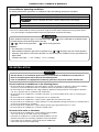
SAFETY CAUTION
• Please read this “Safety Cautions” thoroughly before installation to install the air conditioner
and flow selector correctly.
• The important contents concerned to the safety are described in the “Safety Cautions”.
Be sure to keep them. For Indications and their meanings, see the following description.
n Explanation of indications
WARNING
Indicates possibilities that a death or serious injury of personnel is caused by an incorrect handling.
CAUTION
Indicates contents that an injury (∗1) or property damage (∗2) only may be caused when an incorrect work has
been executed.
∗1 : “Injury” means a hurt, a burn, or an electric shock which does not require hospitalization or a long-term going to
the hospital.
∗2 : “Property damage means an enlarged damage concerned to property, or breakage of materials.
• After installation work has finished, check there is no trouble by a test operation, and explain
using method and maintenance method to the customers based on the Owner’s Manual.
Please ask the customers to keep this Installation Manual together with the Owner’s Manual.
25
WARNING
Ask a shop or a professional dealer to install the air conditioner.
If you will install by yourself, a fire, an electric shock, or water leak is caused.
Using the tool or piping materials exclusive to R410A, install the air conditioner surely
according to this Installation Manual.
The pressure of the used HFC system R410A refrigerant is higher approx. 1.6 times of that of the former refrigerant.
If the exclusive piping materials are not used, or there is imperfection in installation, a crack or an injury is
caused and also a water leak, an electric shock, or a fire may be caused.
Take measures so that the refrigerant does not exceed the limit concentration even if it leaks
when installing the air conditioner in a small room.
For the measures not to exceed the limit of concentration, contact the dealer. If the refrigerant leaks and it
exceeds the limit of concentration, an accident of oxygen shortage is caused.
Install the air conditioner at a place which is satisfactorily bearable to weight.
If strength is insufficient, the unit may fall down resulting in human injury.
Perform a specified installation work against a strong wind such as typhoon or earthquake.
If the air conditioner is imperfectly installed, an accident by falling or dropping may be caused.
If refrigerant gas leaks during installation work, ventilate the room.
If the leaked refrigerant gas approaches to fire, noxious gas may generate.
After installation work, confirm that refrigerant gas does not leak.
If refrigerant gas leaks in the room, and approaches to fire such as fan heater, stove or kitchen range,
generation of noxious gas may be caused.
Never recover refrigerant in the outdoor unit.
Be sure to use a refrigerant recovery device to recover refrigerant in reinstallation or repair work.
Recovery of refrigerant in the outdoor unit is unavailable; otherwise a serious accident such as crack or human
injury is caused.
A person qualified for the electric work should deal with the electric construction conforming
to the regulations of the local electric company and the Installation Manual. Be sure to use the
exclusive circuit.
If there is capacity shortage of the power supply circuit or incomplete installation, a fire or an electric shock is
caused.
For cabling, use the specified cables and connect them securely so that external force of
cable does not transmit to the terminal connecting section.
If connection or fixing is incomplete, a fire, etc may be caused.
Be sure to connect earth wire.
Do not connect earth wire to gas pipe, water pipe, lightning rod, nor earth wire of telephone.
If grounding is incomplete, an electric shock is caused.
CAUTION
Do not install the air conditioner at a place where combustible gas may leak.
If gas leaks and is collected at surrounding the unit, the production of fire may be caused.
Be sure to attach an earth leakage breaker; otherwise an electric shock may be caused.
Using a torque wrench, tighten the flare nut in the specified method.
If the flare nut is exceedingly tightened, the flare nut is broken and a refrigerant leakage may be caused after a
long time has passed.
26
ENGLISH
Outdoor Unit / INSTALLATION MANUAL [ VOLUME-1 ]
1
Outdoor Unit / INSTALLATION MANUAL [ VOLUME-1 ]
INSTALLATION OF NEW REFRIGERANT AIR CONDITIONER
This air conditioner adopts the new HFC refrigerant (R410A) which does not deplete the ozone layer.
• R410A refrigerant is apt to be affected by impurity such as water, oxidizing membrane, or oils because the
pressure of R410A refrigerant is higher than that of the former refrigerant by approx. 1.6 times. Accompanied with
adoption of the new refrigerant, refrigerating oil has been also changed. Therefore pay attention so that water,
dust, former refrigerant, or refrigerating oil does not enter into the refrigerating cycle of the new refrigerant air
conditioner during installation work.
• To prevent from mixing of refrigerant or refrigerating oil, the size of charge port of the main unit or connecting
section of installation tool differs from that of the air conditioner for the former refrigerant. Accordingly the
exclusive tools are required for the new refrigerant (R410A) as shown below.
• For connecting pipes, use the new and clean piping materials so that water or dust does not enter.
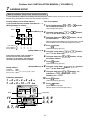
Required tools and cautions on handling
It is necessary to prepare the tools and parts as described below for the installation work.
The tools and parts which will be newly prepared in the following items should be restricted to the exclusive use.
Explanation of symbols
l : Newly prepared (It is necessary to use it properly exclusive to R410A separated from those for R22 or R407C.)
¡: Former tool is available.
Used tools
Gauge manifold
Charging hose
Usage
Proper use of tools/parts
Vacuuming or charging of
refrigerant and operation check
l Newly prepared, Exclusive to R410A
l Newly prepared, Exclusive to R410A
Charging cylinder
Charges refrigerant
Unusable (Use the Refrigerant charging balance.)
Gas leak detector
Checks gas leak
l Newly prepared
Vacuum pump
Vacuum drying
Usable if a counter-flow preventive adapter is attached
Vacuum pump with counterflow preventive adapter
Vacuum drying
¡ : R22 (Existing article)
Flare tool
Flare processing of pipes
¡ : Usable by adjusting size
Bender
Bending processing of pipes
¡ : R22 (Existing article)
Refrigerant recovery device
Recovers refrigerant
l Exclusive to R410A
Torque wrench
Tightens flare nut
l Newly prepared, exclusive to Ø12.7mm and Ø15.9mm
Pipe cutter
Cuts pipes
¡ : R22 (Existing article)
Refrigerant cylinder
Charges refrigerant
l Exclusive to R410A
Welding machine/
Nitrogen gas cylinder
Welding of pipes
¡ : R22 (Existing article)
Refrigerant charging balance
Charges refrigerant
¡ : R22 (Existing article)
ID : Refrigerant name entered
27
2
Outdoor Unit / INSTALLATION MANUAL [ VOLUME-1 ]
SELECTION OF INSTALLATION PLACE
WARNING
Install the air conditioner certainly at a place bearable to weight.
If strength is insufficient, the unit may fall down resulting in human injury.
CAUTION
Do not install the air conditioner at a place where combustible gas may leak.
If gas leaks and is collected at surrounding the unit, the production of fire may be caused.
Upon customer’s approval, install the air conditioner at a place where satisfies the following
conditions.
• Place where it can be installed horizontally.
• Place which can reserve a sufficient service space for safe maintenance or check.
• Place where there is no problem even if the drained water flows.
Apply electric insulation between metal section of the building and metal section of the air
conditioner in conformance with the Local Regulation.
Avoid the following places.
• Salty place (seaside area) or place with much gas sulfide (hot spring area)
(If selecting such a place, a special maintenance is required.)
• Place where oil (including machine oil), steam, oil smoke or corrosive gas generates.
• Place where a device generating high frequency (inverter, non-utility generator, medical apparatus, or
communication equipment) is set. (A bad influence may generate by malfunction of the air conditioner, control
error, or noise for such equipment.)
• Place where discharged air of the outdoor unit blows against windows of neighbor.
• Place where operation sound of the outdoor unit transmits.
(Especially at the boundary line with neighbor, install the air conditioner considering the noise.)
• Place unbearable to weight of the unit.
• Place with ill ventilation.
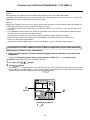
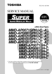
Installation space
Considering functions, reserve space necessary for installation work and servicing.
Outdoor unit top view
Air outlet
(Rear side)
500mm or more
Air inlet
Air inlet
10mm
or more
Air inlet
500mm or more
Air inlet
20mm or more
20mm or more
10mm
or more
(Front side)
(A case of 3 units are installed.)
Installation work/
servicing surface
Square hole for handling
NOTES)
∗1 : If there is an obstacle at the upper side of the outdoor unit, reserve
a space by 2000mm or more to the top end of the outdoor unit.
∗2 : Arrange the height of obstacle around two outdoor units up to
below 800mm from the bottom end of the outdoor unit.
28
Outdoor Unit / INSTALLATION MANUAL [ VOLUME-1 ]
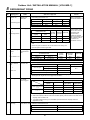
2
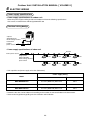
SELECTION OF INSTALLATION PLACE
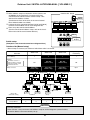
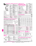
Equipments
Inverter unit
Equivalent HP
8 HP
10 HP
12 HP
MMY-MAP0801FT8
MMY-MAP1001FT8
MMY-MAP1201FT8
Cooling capacity (kW)
22.4
28.0
33.5
Heating capacity (kW)
25.0
31.5
35.5
Model name
Appearance
3
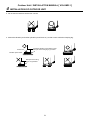
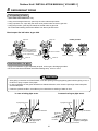
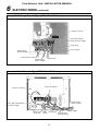
OUTDOOR UNIT CARRYING IN
Handle the outdoor unit in care with the following items.
1. When using a forklift, etc for loading/unloading in transportation, insert pawl of the forklift into the
square hole for handling as shown below.
2. When lifting up the unit, insert a rope sufficiently bearable to unit mass into the square hole for handling,
and cord the unit from four sides. (Apply a plaster to position where rope fits outdoor unit itself so that
flaw or deformation does not generate on the outer surface of the outdoor unit.)
(There provided the reinforcing plates on the side surfaces, so the rope cannot be passed.)
Plaster
Forklift
Rope
Forklift
Plaster
Square hole for handling
29
Reinforcing plate
4
Outdoor Unit / INSTALLATION MANUAL [ VOLUME-1 ]
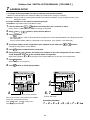
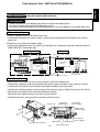
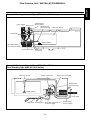
INSTALLATION OF OUTDOOR UNIT
WARNING
Perform a specified installation work against a strong wind such as typhoon or earthquake.
If the air conditioner is imperfectly installed, an accident by falling or dropping may be caused.
Install the air conditioner certainly at a place bearable to weight.
If strength is insufficient, the unit may fall down resulting in human injury.
Drain water is discharged from the outdoor unit. (Especially in heating time)
Install the outdoor unit at a place where has good drainage.
For installation, be careful to the strength and the level of the foundation so that an abnormal
sound (Vibration, noise) does not generate.
Snowfall-hood
for air outlet
In the snowfall area, apply the following measures against
snowfall for the outdoor unit. (See the figure on the right.)
(Incomplete snowfall-proof measures causes a trouble.)
Place a higher stool under the unit, and mount the
snowfall-hoods to air inlet and air outlet so that
snows do not have influence.
(For the above works, please arrange at the field.)
Snowfall-hood
for air inlet
(4 faces)
Stool
Space for draining
20mm or more
20mm or more
1. To install the multiple outdoor units, arrange them with
20mm or more intervals.
Fix each outdoor unit with M12 anchor bolts at 4 positions.
Length by 20mm is appropriate for an anchor bolt.
M12 anchor bolt
4 positions/unit
20
• Anchor bolt pitch is as shown below:
700
*310 or more
700
Continuous hole
(15 x 20 long hole)
2. When drawing out the refrigerant pipe from underside, set
height of the stool by 500mm or more.
30
500mm or more
310 or more
755
700
Outdoor Unit / INSTALLATION MANUAL [ VOLUME-1 ]
4
INSTALLATION OF OUTDOOR UNIT
3. Do not use four stools to set the four corners.
4. Mount the vibration-proof rubber (vibration-proof block etc.) so that it catch whole the clamping leg.
Anchor bolt
Install the vibration-proof rubber so that
bent part of the fixing leg is grounded.
Vibration-proof rubber
Bent part of the fixing
leg is not grounded.
31
Outdoor Unit / INSTALLATION MANUAL [ VOLUME-1 ]
5
REFRIGERANT PIPING
WARNING
If the refrigerant gas leaks during installation work, ventilate the room.
If the leaked refrigerant gas comes to contact with a fire, the noxious gas may generate.
After installation work, check that the refrigerant gas does not leak.
If the refrigerant gas leaks in the room and comes to contact with a fire such as fan heater, stove, or kitchen
range, the noxious gas may generate.
Connection of refrigerant pipe
1. The refrigerant pipe connecting section is set in the outdoor unit. Remove the front panel and the piping/wiring
panel. (M5: 9 pcs.)
• As shown in the right figure, the hooking hooks are attached at right and left sides each on the front panel.
Lift up and remove the front panel.
2. Pipes can be drawn out forward and downward from the outdoor unit.
3. When drawing out the pipe forward, draw out the pipe to outside via piping/wiring panel, and keep space of
500mm or more from the main pipe connecting the outdoor unit with the indoor unit, considering service work,
etc. (For replacing the compressor, 500mm or more space is required.)
4. When drawing out the pipe downward, remove the knockout of the base plate of the outdoor unit, apply the pipe
to outside of the outdoor unit, and perform piping at right/left or rear side. Leading pipe of the balancing should
be within 4m.
Hook
Packed valve at
suction gas side
5
or 00m
m m
or
e
Packed valve
at liquid side
(Left piping)
Front panel
Piping/wiring panel
(Right
piping)
Drawing out
forward
(Left piping)
Packed valve at balance side
(It is not used in this model.)
(Rear piping)
Ball valve at discharge gas side
(Right piping)
Drawing out
downward
REQUIREMENT
For brazing, be sure to use nitrogen gas to avoid oxidation of pipe inside.
1. In a welding work for the refrigerant pipes, be sure to use the nitrogen gas in order to prevent oxidation inside
of the pipes; otherwise clogging of the refrigerating cycle due to oxidized scale generates.
2. Use clean and new pipes for the refrigerant pipes and perform piping work so that water or dust is not mixed.
3. Be sure to use a double spanner to loosen or
Outer dia. of copper pipe Tightening torque (N•m)
tighten the flare nut. If a single spanner is used, a
required tightening cannot be obtained. Tighten
12.7 mm
50 to 62 (5.0 to 6.2 kgf-m)
the flare not with the specified torque.
15.9 mm
32
68 to 82 (6.8 to 8.2 kgf-m)
Outdoor Unit / INSTALLATION MANUAL [ VOLUME-1 ]
5
REFRIGERANT PIPING
Pipe connecting method of valve (Example)
Using the attached pipes as shown in the following figure, braze elbows, sockets, and pipes which are procured locally.
MMY-
Drawing out forward
Drawing out downward
Liquid pipe
Use the attached pipe for connection.
Pipe connection at the local site
(Bend rightward slightly.)
Discharge gas pipe
Use the attached pipe (L-shape) and connect it with
socket.
Use the attached pipe (Straight pipe) and connect it
with socket.
Suction gas pipe
Cut L-shape pipe and connect it with elbow, attached Cut L-shape pipe and connect it with attached pipe
pipe and socket.
and socket.
Suction gas pipe
Suction gas pipe
Cut
Discharge
gas pipe
MAP0801FT8
MAP1001FT8
Liquid pipe
Suction gas pipe
Cut
Discharge
gas pipe
Liquid pipe
L-shape pipe
L-shape pipe
Attached pipe
Pipe
Attached
pipe
Attached pipe
Attached pipe
Socket
Pipe
Socket
Attached pipe
Socket
Socket
Pipe
Liquid pipe
Suction gas pipe
Pipe
Pipe
Pipe
Pipe connection at the local site
(Bend rightward slightly.)
Use the attached pipe for connection.
Discharge gas pipe Use the attached pipe and connect it with socket.
Use the attached pipe (Straight pipe) and connect it
with socket.
Suction gas pipe
Cut L-shape pipe and connect it with attached pipe
and socket.
Cut L-shape pipe and connect it with attached pipe.
Suction gas pipe
MAP1201FT8
Suction gas pipe
Cut
Discharge
gas pipe
Suction gas pipe
Suction gas pipe
Discharge
gas pipe
Cut
Liquid pipe
Liquid pipe
L-shape pipe
L-shape pipe
Attached pipe
Attached
pipe
Attached pipe
Pipe
Socket
Pipe
Attached pipe
Socket
Socket
Pipe
Pipe
Pipe
Pipe
Rigid (Clutch type)
Copper pipe outer dia.
12.7
15.9
Imperial (Wing nut)
R410A tool used
Conventional tool used
0 to 0.5
1.0 to 1.5
∗ When using the conventional flare tool, to
connect R410A pipes with flaring, make a
margin approx. 0.5mm longer than that of R22
pipe so that the flare size matches with the
specified one. It is convenient to use a copper
pipe gauge for size adjustment of the extruding
margin.
B
• Extruding margin of copper pipe with flare machining : B (Unit: mm)
2.0 to 2.5
• Extruding margin of copper pipe with flare tools :
A (Unit: mm)
Copper pipe outer dia.
A +0.0
–0.4
12.7
16.6
15.9
19.7
33
A
Outdoor Unit / INSTALLATION MANUAL [ VOLUME-1 ]
• Coupling size of brazed pipe
Connected section
External size
Internal size
G
ØF
ØC
K
(Unit: mm)
Connected section
External size
Standard outer dia. of
connected copper pipe
Internal size
Standard outer dia. (Allowable difference)
C
6.35
F
6.35 (±0.03)
6.45 (
+0.04
–0.02
Min. depth
of insertion
Oval value
Min. thickness
of coupling
K
G
)
7
6
0.06 or less
0.50
9.52
9.52 (±0.03)
9.62 (
+0.04
–0.02
)
8
7
0.08 or less
0.60
12.70
12.70 (±0.03)
12.81 (
+0.04
–0.02
)
9
8
0.10 or less
0.70
16.00 (
+0.04
–0.02
)
9
8
0.13 or less
0.80
15.88
15.88 (±0.03)
19.05
19.05 (±0.03)
19.19 (
+0.03
–0.03
)
11
10
0.15 or less
0.80
22.22
22.22 (±0.03)
22.36 (
+0.03
–0.03
)
11
10
0.16 or less
0.82
28.75 (
+0.06
–0.02
)
13
12
0.20 or less
1.00
28.58
28.58 (±0.04)
Selection of pipe materials and size
• Selection of pipe material
Material: Phosphorus deoxidation seam-less pipe
• Capacity code of indoor and outdoor units
• For the indoor unit, the capacity code is decided at each capacity rank.
• The capacity codes of the outdoor units are decided at each capacity rank. The maximum No. of connectable
indoor unit and the total value of capacity codes of the indoor units are also decided.
• When height difference between the indoor units is below 15m: Up to 135% of capacity code of the outdoor unit
(in case of MMY-MAP1201FT: 120% or less)
• When height difference between the indoor units is over 15m: Up to 105% of capacity code of the outdoor unit
Compared with the capacity code of the outdoor unit, the total value of capacity codes of the connectable indoor
units differs based on the height difference between the indoor units.
Table 1
Table 2
Capacity code
Indoor unit
capacity rank Equivalent to Equivalent to
HP
capacity
Total capacity code of connectable indoor units
Capacity code
Outdoor unit
model name
Min
No. of
indoor units
007 type
0.8
2.2
009 type
1
2.8
012 type
1.25
3.6
MMY-MAP0801FT8
8
22.4
015 type
1.7
4.5
MMY-MAP1001FT8
10
018 type
2
5.6
MMY-MAP1201FT8
12
024 type
2.5
7.1
027 type
3
8
030 type
3.2
9
036 type
4
11.2
048 type
5
14
056 type
6
16
Equivalent to Equivalent to
HP
capacity
34
Max.
Equivalent
to HP
Equivalent
to capacity
Equivalent
to HP
Equivalent
to capacity
13
5.6
15.7
10.8
30.2
28.0
16
7.0
19.6
13.5
37.8
33.5
16
8.4
23.5
14.4
40.2
Outdoor Unit / INSTALLATION MANUAL [ VOLUME-1 ]
5
No.
REFRIGERANT PIPING
Piping parts
Outdoor unit
Name
Outdoor unit
main pipe
↓
1st branching joint
Branching section Branching pipe
↓
Selection of pipe size
1) Connecting pipe outdoor unit
Same to connecting
pipe size of outdoor unit
Model name
Suction gas side
Discharge gas side Liquid side
MMY-MAP0801FT8
Ø22.2
Ø19.1
Ø12.7
MMY-MAP1001 FT8
Ø22.2
Ø19.1
Ø12.7
MMY-MAP1201 FT8
Ø28.6
Ø19.1
Ø12.7
2) Pipe size between branching sections
Total capacity codes of indoor units
at downstream side
Branching section
Remarks
Equivalent to
capacity
Equivalent
to HP
Below 18.0
Below 6.4
Suction
gas side
Pipe size differs based
on total capacity code
value of indoor units at
downstream side.
Discharge
Liquid side
gas side
Ø15.9
Ø12.7
Ø9.5
18.0 to below 34.0 6.4 to below 12.2
Ø22.2
Ø19.1
Ø12.7
34.0 to below 45.5 12.2 to below 16.2
Ø28.6
Ø22.2
Ø15.9
If the total value
exceeds the capacity
code of the outdoor unit,
apply capacity code of
the outdoor unit.
(See tables 1 and 2.)
∗ If exceeding the main pipe size, decide the size same to main pipe
size.
∗ When two pipes are used for the circuits exclusive to cooling, use
pipes at liquid and suction gas sides.
End branching
section
Connecting pipe
of flow selector
unit
↓
3) Pipe size between end branching section and flow selector unit
Total capacity codes of indoor units
at downstream side
Equivalent to capacity
Flow selector unit
Suction
gas side
Discharge
gas side
Liquid side
Equivalent to HP
Below 4.5
Below 1.7
Ø12.7
Ø9.5
Ø6.4
4.5 to below 18.0
1.7 to below 6.4
Ø15.9
Ø12.7
Ø9.5
Branching section Connecting pipe 4) Connecting pipe size of indoor unit
or flow selector
unit
of indoor unit
Capacity rank
↓
007 to 012 type
Indoor unit
Gas side
Real length: Below 15m
Ø9.5
Real length: Over 15m ∗
Ø12.7
015 to 018 type
Ø12.7
024 to 056 type
Ø15.9
Liquid side
Ø6.4
Ø9.5
∗ When pipe length between the end branching section and cooling-only indoor unit exceeds 15m,
decide pipe size at gas side to the bigger one with Ø12.7.
Branching section Branching header 5) Selection of branching joint/header
of Y-shape
branching joint
Total capacity codes of indoor units
Equivalent to
capacity
Below 18.0
Y-shape branching joint
∗ 1, 2
18.0 to below 40.0
Branching header
∗ 1, 2, 3
Model name
RBM-
Equivalent to HP
For 3
pipes piping
For 2
pipes piping
Below 6.4
BY53FE
BY53E
6.4 to below 14.2
BY103FE
BY103E
Below 40.0
Below 14.2
HY1043FE
HY1043E
Below 40.0
Below 14.2
HY1083FE
HY1083E
∗1 For branching pipe of the 1st branching section, select one by the outdoor unit capacity code.
∗2 When total capacity codes of indoor units exceed capacity code of outdoor unit, select one by
capacity code of outdoor unit.
∗3 1 line after header branching is connectable up to total maximum capacity codes 6.0
(Equivalent to HP).
Branching
Flow selector unit 6) Selection of flow selector unit
Model name
Capacity rank of connectable indoor unit
RBM-Y1121FE
007 to 030 type
RBM-Y1801FE
036 to 056 type
∗ Confirm also Installation Manual of flow selector unit.
35
Outdoor Unit / INSTALLATION MANUAL [ VOLUME-1 ]
Minimum wall thickness for R410A application
Soft
Half Hard or Hard
OD (Inch)
OD (mm)
OK
OK
1/4”
6.35
OK
OK
3/8”
9.52
OK
OK
1/2”
12.70
OK
OK
5/8”
15.88
NG
OK
3/4”
19.05
NG
OK
7/8”
22.20
NG
OK
1.1/8”
28.58
Minimum wall thickness (mm)
0.80
1.00
Outdoor unit
5 For three pipes piping
Suction gas pipe
3
3
3
Discharge gas pipe
2
2
2
Liquid pipe
5 For two pipes piping
1st
branching
section
6
4
1
6
Indoor unit
6
4
4
4
<Cooling
only>
4
<Cooling
only>
5 For three pipes piping
5 For two pipes piping
2
2
3
3
6
3
6
4
4
6
4
4
4
<Cooling only> <Cooling only>
FS unit
FS unit
Indoor unit
Indoor unit
[NOTE] :
Don’t connect two or more indoor units to one FS unit. Arrange one indoor unit and one FS unit set to 1 by 1.
36
Outdoor Unit / INSTALLATION MANUAL [ VOLUME-1 ]
5
REFRIGERANT PIPING
Allowable length of refrigerant pipe and height difference
Outdoor unit
Main
piping
L1
Branching
header
Branching pipe L2
Connecting piping of indoor unit
1st branching
section
Height difference
between outdoor unit
and indoor unit
H1 50 m
(Outdoor at upper side)
a
L7
b
FS unit
g
c
FS unit
h
FS unit
i
j
Indoor unit
L3
k
<Cooling only>
Equivalent length corresponded to farthest piping L
125 m
Equivalent length corresponded to farthest piping after 1st branching Li
Y-joint
L4
L5
L6
d
e
f
FS unit
l
FS unit
m
50 m
Height difference
between indoor units
H2 35 m
(Outdoor at upper side)
FS unit
n
<Cooling only>
<Cooling only>
o
p
Indoor unit
<Cooling only>
• Allowable length/height difference of the refrigerant pipe
Pipe
length
Allowable
value
Pipe section
Total extended pipe length
(Liquid pipe/real length)
250m
L1 + L2 + L3 + L4 + L5 + L6 + L7 + a + b + c
+d+e+f+g+h+i+j+k+l+m+n+o+p
Farthest equivalent piping length L (*1)
125m
L1 + L3 + L4 + L5 + L6 + p
Max. equivalent length of main pipe
85m
L1
Farthest equivalent piping length from 1st branch Li (*1)
50m
L3 + L4 + L5 + L6 + p
Farthest equivalent piping length between indoor unit and end
branching section
30m
a + g, b + h, c + i, d + l, e + m, f + n, j, k, o, p.
Max. real length between flow selector unit and indoor unit
15m
g, h, i, l, m, n
Outdoor at upper side
50m
——
Outdoor at lower side
30m
——
Outdoor at upper side
35m
——
Outdoor at lower side
15m
——
Height difference between
indoor unit and outdoor unit
H1
Height difference between
indoor units
H2
Height
difference
∗1 : The farthest indoor unit from 1st branch is (p).
37
Outdoor Unit / INSTALLATION MANUAL [ VOLUME-1 ]
Airtight test
After the refrigerant piping has finished, execute an airtight test. For an airtight test, connect a nitrogen gas bomb as
shown in the figure below, and apply pressure.
• Be sure to apply pressure from the service ports of the packed valves (or ball valves) at liquid side, discharge gas
side, and suction gas side.
• An air tight test can be only performed to the service ports at liquid side, discharge gas side, and suction gas side
of the outdoor unit.
• Close fully valves at liquid side, discharge gas side, and suction gas side. As there is possibility that nitrogen gas
enters in the refrigerant cycle, re-tighten the valve rods before applying pressure.
(Re-tightening of the valve rods are unnecessary for valves at discharge gas side because they are ball valves.)
• For each refrigerant line, apply pressure gradually with steps at liquid side, discharge gas side, and suction gas
side.
Be sure to apply pressure to suction gas side, discharge gas side, and liquid side.
REQUIREMENT
Never use “Oxygen”, “Flammable gas” and “Noxious gas” in an airtight test.
LowHighpressure pressure
gauge
gauge
Connected to indoor unit
Packed valve fully closed
(Suction gas side)
Outdoor unit
Main pipe
Detailed drawing of packed valve
Brazed
Suction gas side
service port
To gauge manifold
Suction gas side
packed valve
Discharge gas side
service port
To outdoor
unit
To
outdoor
unit
Liquid side
service port
Piping
at site
VH Gauge
manifold
Reducing
valve
Fully
closed
Service port
Discharge gas side
ball valve
Liquid side
packed valve
Service
port
Ø6.4
Copper pipe
VL
Ball valve fully closed
(Discharge gas side)
Fully
closed
Ø6.4
Copper
pipe
Nitrogen
gas
Piping
at site
Packed valve fully closed
(Liquid side)
To outdoor unit
Piping at site
STEP 1 : Apply pressure 0.3MPa (3.0kg/cm2G) for 3 minutes or more.
Available to detect a gross leakage
STEP 2 : Apply pressure 1.5MPa (15kg/cm2G) for 3 minutes or more.
STEP 3 : Apply pressure 3.73MPa (38kg/cm2G) for approx. 24 hours.
Available to detect slow leakage
• Check pressure down.
No pressure down: Accepted
Pressure down: Check the leaked position.
However, if there is difference of ambient temp. between when pressure has been applied and when
24 hours passed, pressure changes by approx. 0.01MPa (0.1kg/cm²G) per 1°C. Correct the pressure.
Leaked position check
When a pressure-down is detected in STEP 1, STEP 2, or STEP 3, check the leakage at the connecting points.
Check leakage with hearing sense, feeler, foaming agent, etc, and perform re-brazing or re-tightening of flare if
leakage is detected.
38
Outdoor Unit / INSTALLATION MANUAL [ VOLUME-1 ]
5
REFRIGERANT PIPING
Air purge
For the air purge at installation time (Discharge of air in connecting pipes), use “Vacuum pump method” from
viewpoint of protection of earth environment.
• For protection of earth environment, do not discharge the flon gas in the air.
• Using a vacuum pump, eliminate the remained air (nitrogen gas, etc.) in the unit. If gas remains, an absence
of faculties may be caused.
After the airtight test, discharge nitrogen gas. Then connect the gauge manifold to the service ports at suction gas
side, discharge gas side and liquid side, and connect the vacuum pump as shown in the following figure.
Be sure to perform vacuuming for suction gas side, discharge gas side and liquid side.
• Be sure to perform vacuuming from both suction gas side, discharge gas side and liquid side.
• Be sure to use a vacuum pump with counter-flow preventive function so that oil in the pump does not back up in
the pipe of the air conditioner while the pump stops. (If oil in the vacuum pump enters in the air conditioner with
R410A refrigerant, a trouble is caused in the refrigerating cycle.)
LowHighpressure pressure
gauge
gauge
Connected to indoor unit
Packed valve fully closed
(Suction gas side)
Outdoor unit
Main pipe
Detailed drawing of packed valve
VL
VH Gauge
manifold
Brazed
Suction gas side service port
Discharge gas side
service port
Liquid side
packed valve
Fully
closed
Service port
Discharge gas side
ball valve
Liquid side
service port
Service
port
Suction gas side
packed valve or
ball valve
To gauge manifold
To outdoor
unit
To
outdoor
unit
Piping
at site
Fully
closed
Ball valve fully closed
(Discharge gas side)
P
Vacuum pump
Piping
at site
Packed valve fully closed
(Liquid side)
To outdoor unit
Piping at site
• Use a vacuum pump having a high vacuuming degree (below –755mmHg) and a large exhaust gas amount (over
40L/minute).
• Perform vacuuming for 2 or 3 hours though time differs due to pipe length. In this time, check all packed valves at
suction gas, discharge gas, and liquid sides are fully closed.
• If vacuuming valve amount is not decreased to below –755mmHg even after vacuuming for 2 hours or more,
continue vacuuming for 1 hour or more. If –755mmHg or less cannot be obtained by 3 hours or more vacuuming,
check the leaked position.
• When vacuuming valve reached to –755mmHg or less after vacuuming for 2 hours or more, close valves VL and
VH of the gauge manifold fully, stop the vacuum pump, leave it as it is for 1 hour, and then check the vacuuming
degree does not change. If it changed, there may be a leaked position. Check the leaked position.
• After the above procedure of vacuuming has finished, exchange the vacuum pump with a refrigerant cylinder and
advance to the additional charging of refrigerant.
39
Outdoor Unit / INSTALLATION MANUAL [ VOLUME-1 ]
Addition of refrigerant
After vacuuming work, exchange the vacuum pump with the refrigerant bomb and then start the additional charging
work of refrigerant.
Calculation of additional refrigerant charge amount
Refrigerant charge amount at shipment from the factory does not include the refrigerant for pipe at the local site.
For refrigerant to be charged in pipe at the local site, calculate the amount and charge it additionally.
NOTE) If the additional refrigerant amount indicates minus as the result of calculation, use the air conditioner
without addition of refrigerant.
Outdoor unit Model
MMY-MAP0801FT8
MMY-MAP1001FT8
Charging amount (kg)
Additional refrigerant
charge amount at local site
MMY-MAP1201FT8
14.0
=
Real length of
liquid pipe
Additional refrigerant charge
amount per 1m liquid pipe (Table 1)
×
×
1.3
Example : Additional charge amount R (kg) = {(L1 × 0.025kg/m) + (L2 × 0.055kg/m) + (L3 × 0.105kg/m)} × 1.3
L1 : Real total length of liquid pipe Ø6.4 (m)
L2 : Real total length of liquid pipe Ø9.5 (m)
L3 : Real total length of liquid pipe Ø12.7 (m)
System : 10HP
Table-1
Liquid pipe dia. (mm)
Additional refrigerant amount/1m liquid pipe (kg/m)
6.4
9.5
12.7
0.025
0.055
0.105
Charging of refrigerant
• Keeping valve of the outdoor unit closed, be sure to charge the liquid refrigerant into service port at liquid side.
• If the specified amount of refrigerant cannot be charged, open fully valves of outdoor unit at liquid and discharge/
suction gas sides, operate the air conditioner in COOL mode under condition that valve at suction gas side is a
little returned to close side, and then charge refrigerant into service port at suction gas side. In this time, choke the
refrigerant slightly by operating valve of the bomb to charge liquid refrigerant. The liquid refrigerant may be
charged suddenly, therefore be sure to charge refrigerant gradually.
• When refrigerant leaks and refrigerant shortage occurs in the system, recover the refrigerant in the system and
recharge refrigerant newly up to the correct level.
REQUIREMENT
<Entry of refrigerant charge amount>
• Fill the additional refrigerant record column of the wiring diagram indication plate with the additional refrigerant
amount at installation work, total refrigerant amount and the name of the service man who charged refrigerant
at installation time.
• The total refrigerant amount means the total value of the refrigerant amount at shipment and the additional
refrigerant amount at installation time. The refrigerant amount at the shipment is one described on the “Unit
nameplate”.
40
Outdoor Unit / INSTALLATION MANUAL [ VOLUME-1 ]
5
REFRIGERANT PIPING
Full opening of valve
•
•
•
•
Open valve of the outdoor unit fully.
Using 4mm-hexagonal wrench, open fully the valve rods at liquid sides.
Using a spanner, etc, open fully the valve rod of packed valve at suction gas side.
Using the pinchers, open fully the handle of the ball valve at gas side.
Be careful that handling of ball valve differs from that of packed valve.
How to open the ball valve at gas side
Valve unit
Charge port
Valve unit
Handle
Pull out the handle and
using cutting pliers, etc.
turn it counterclockwise
by 90˚. (Open fully)
Charge port
Handle position
Push in handle.
Handle
Closed completely
Opened fully
Flare nut
Flare nut
Heat insulation for pipe
• Apply heat insulation of pipe separately at liquid, suction gas, discharge gas sides.
• Be sure to use thermal insulator with heat-resisting temp. 120°C or more.
CAUTION
• After piping connection work has finished, cover the opening of the piping/wiring panel with the piping cover, or
fill silicon or putty in space of the pipes.
• In case of drawing-out the pipes downward or sideward direction, also close the openings of the base plate
and the side plate.
• Under the opened condition, a trouble may be caused due to entering of water or dust.
In case of using pipe cover
In case of using no pipe cover
Piping/wiring panel
Piping/wiring panel
Drawing-out sideward
Drawing-out sideward
Drawing-out
frontward
Drawing-out
frontward
Close the opening
with pipe cover.
Drawing-out downward
Fill silicon or putty in
periphery of the pipes.
Drawing-out downward
41
Outdoor Unit / INSTALLATION MANUAL [ VOLUME-2 ]
6
ELECTRIC WIRING
WARNING
Using the exclusive circuit, a person qualified for electrician shall work for the electric work in
conformance with the regulations of the local electric company and the Installation Manual.
If there is capacity shortage of the power circuit or incomplete electric work, a fire or electric shock is caused.
For wiring, use the specified wires and connect them securely so that external force of wire does
not transmit to the terminal connecting section.
If connection or fixing is incomplete, a fire is caused.
Be sure to connect the earth wire.
Grounding work is necessary based upon a law. If the earth grounding is incomplete, an electric shock is caused.
Do not connect earth wire to gas pipe, lightning rod, or earth wire of telephone.
CAUTION
Be sure to attach an earth leakage breaker; otherwise an electric shock may be caused.
To Disconnect the Appliance from Main Power Supply.
This appliance must be connected to the main power supply by means of a switch with a contact separation of at
least 3 mm.
REQUIREMENT
• Perform wiring of the power supply in conformance with the regulations of the local electric company.
• For wiring of power supply in the indoor unit, refer to the Installation Manual of each indoor unit.
• Never connect the 220–240V power to the terminal block (U1, U2, U3, U4, U5, U6) for control wires.
(Trouble is caused.)
• Arrange the wires so that the electric wires do not come to contact with high-temperature part of the pipe;
otherwise coating melts and an accident may be caused.
• After connecting wire to the terminal block, take off the trap and then fix the cable with wire clamp.
• Store wiring system for control and refrigerant piping system in the same line.
• Do not turn on power of the indoor unit until vacuuming of the refrigerant pipe will finish.
• For wiring of the power supply of the indoor unit and the inter-unit cabling between indoor and outdoor units, refer to
the Installation Manual of indoor unit.
42
Outdoor Unit / INSTALLATION MANUAL [ VOLUME-2 ]
6
ELECTRIC WIRING
Power supply specifications
• Power supply specifications of outdoor unit
Select the power supply cabling and fuse of outdoor unit from the following specifications:
wire 5-core, in conformance with Design 60245 IEC 66
Electrical wiring design
3-phase
50Hz 380-415V
Earth
Earth leakage breaker
hand switch
Outdoor
power source
• Power supply specifications of indoor unit
Pull box
Indoor power source
Single phase
50Hz 220-240V
Earth leakage breaker
power switch
FS unit
FS unit
FS unit
FS unit
FS unit
FS unit
FS unit
FS unit
• Unit capacities and power supply wire sizes (Reference)
Power supply wiring
Model
Wire size
Field fuse
MMY-MAP0801FT8
3.5 mm² (AWG #12) Max. 20 m
30 A
MMY-MAP1001FT8
5.5 mm² (AWG #10) Max. 28 m
30 A
MMY-MAP1201FT8
5.5 mm² (AWG #10) Max. 27 m
30 A
• Determine the wire size for indoor unit according to the number of connected indoor units downstream.
• Observe local regulation regarding wire size selection and installation.
43
Outdoor Unit / INSTALLATION MANUAL [ VOLUME-2 ]
Design of control wiring
n Outdoor unit
Voltage range
Compressor
Fan Motor
Power Supply
Model name
MMY-
Nominal voltage
(V-Ph-Hz)
Min.
Max.
RLA
LRA
kW
FLA
MCA
MOCP
ICF
MAP0801FT8
400-3-50
342
457
5.2 + 5.2
—
0.60
1.0
20.0
30
—
MAP1001FT8
400-3-50
342
457
6.5 + 6.5
—
0.60
1.1
22.5
30
—
MAP1201FT8
400-3-50
342
457
9.5 + 9.5
—
0.60
1.1
24.5
30
—
Legend
Power supply
single phase
220-240V 50Hz
(Open)
: Minimum Circuit Amps
: Maximum Overcurrent Protection (Amps)
: Maximum Instantaneous Current Flow Start
: Rated Load Amps
: Locked Rotor Amps
: Full Load Amps
: Fan Motor Rated Output (kW)
NOTE : RLA is based on the following conditions.
Indoor temperature : 27°C DB/19°C WB
Outdoor temperature : 35°C DB
Earth
[Central remote controller] (Option)
TCB-SC642TLE (For Line 64)
Transmission wire for control between
outdoor unit and indoor unit
MCA
MOCP
ICF
RLA
LRA
FLA
kW
Connection of shield wire must be connected
(Connected to all connecting sections in each indoor unit)
FS unit
FS unit
FS unit
FS unit
FS unit
FS unit
FS unit
FS unit
Wired
remote controller
• Wire specification, quantity, size of crossover wiring and remote controller wiring
Size
Name
Q’ty
Specification
Up to 500m
Crossover wiring
(indoor-indoor / indoor-outdoor / outdoorindoor control wiring, central control wiring)
2 cores
Remote controller wiring
2 cores
Indoor unit - FS unit control wiring
Up to 1000m
1.25mm²
0.5 to 2.0mm²
—
1000 to 2000m
2.0mm²
Shield wire
—
—
Use the transmission wire (6m) attached to FS unit. If the indoor unit is placed 5m or more
apart from the FS unit, use the connecting wire (RBC-CBK15FE (16m)) sold separately.
(1) The crossover wiring and central control wiring use 2-core non-polarity transmission wires. Use 2-core shield
wires to prevent noise trouble. In this case, close (connect) the end of shield wires, and perform the functional
grounding for the end of the shield wires which are connected to both indoor and outdoor units.
For the shield wires which are connected between the central remote controller and the
outdoor unit, perform the functional grounding at only one end of central control wiring.
(2) Use 2-core and non-polarity wire for remote controller. (A, B terminals)
Use 2-core and non-polarity wire for wiring of group control. (A, B terminals)
U1 U2 U3 U4 U5 U6
Shield
wire earth
• Specifications of wires for controlling
1. Connect each wire for controlling as shown below.
Earth screw
44
Control wiring between
indoor and outdoor units
Outdoor Unit / INSTALLATION MANUAL [ VOLUME-2 ]
6
ELECTRIC WIRING
• Group Control through a Remote Controller
Group control of multiple indoor units (8 units) through a single remote controller
Indoor unit No.1
No.2
No.3
No.4
AB
AB
AB
AB
Remote
controller
No.7
No.8
AB
AB
(A.B)
For Indoor unit power supply (The outdoor unit has a separate power supply.)
Power supply wiring
Item
Model
Wire size
All models of indoor units
2.0 mm² (AWG#14)
Indoor unit - FS unit power supply wiring
Max. 20m
3.5 mm² (AWG#12)
Max. 50m
Use the communication wire (6m) attached to FS unit.
If the indoor unit is placed 5m or more apart from the FS unit, use the connecting wire
(RBC-CBK15FE (16m)) sold separately
NOTE :
The connecting length indicated in the table represents the length from the pull box to the outdoor unit when the
indoor units are connected in parallel for power, as shown in the illustration below. A voltage drop of no more than
2% is also assumed. If the connecting length will exceed the length indicated in the table, select the wire thickness
in accordance with indoor wiring standards.
Indoor power source
single phase 220–240V, 50Hz
Earth leakage breaker
Switch
Pull box
FS unit
1
FS unit
2
FS unit
5
FS unit
3
FS unit
6
FS unit
4
FS unit
7
FS unit
8
CAUTION
(1) Keep the refrigerant piping system and the indoor-indoor/indoor-outdoor control wiring systems together.
(2) When running power wires and control wires parallel to each other, either run them through separate
conduits, or maintain a suitable distance between them.
(Current capacity of power wires: 10A or less for 300mm, 50A or less for 500mm)
45
Outdoor Unit / INSTALLATION MANUAL [ VOLUME-2 ]
n System wiring diagram
Power supply
3 phase 380-415V 50Hz
Earth leakage breaker
Power swith
Outdoor unit
Earth
terminal
Earth
Earth
U1 U2 terminal U3 U4 U5 U6 terminal
Central remote
controller
Single phase
220-240V 50Hz
U1/U3
Outdoor side
U2/U4
Indoor side
Remote
controller
Indoor unit
U1/U2
Earth terminal
L
A
A
B
B
Control
wiring
Power
line
Power supply
Single phase
220-240V
50Hz
Earth leakage
breaker
Power switch
U1/U2
L
A
B
B
Control
wiring
CN81
N
CN01
Earth
terminal
Earth
terminal
Remote
controller
Indoor unit
A
A
U1/U2
L
B
B
Earth terminal
FS unit
CN02
Power
line
Earth
terminal
Pull
Box
A
Earth terminal
FS unit
CN02
N
Remote
controller
Indoor unit
Control FS unit
wiring
CN02
N
CN01
Power
line
Earth
terminal
CN01
Earth
terminal
Earth
terminal
Pull
Box
NOTE :
Control wire and power wire between FS unit and indoor unit are the accessory parts of FS unit.
(Wire length : 6m)
If the length between indoor and FS unit exceeds 5m, connect by using the connection cable kit sold separately
(RBC-CBK15FE).
46
Outdoor Unit / INSTALLATION MANUAL [ VOLUME-2 ]
6
ELECTRIC WIRING
Connection of power supply wire with control wire
Insert power supply wire and control wire after removing knockout of the piping/wiring panel at front side of the
outdoor unit.
Knockout for power supply wire
Knockout for control wire
Piping/wiring panel
When insert power supply wire
and control wire, protect power supply wire
and control wire from edge after removing knockout.
n Power supply wire
1. Connect the power supply wires and earthing wire to the terminal block of the power supply through a notched
section at side of the electric parts box, and fix with a clamp.
2. Bundle the power supply wires using the hole so that they are not out of the notched section of the electric parts
box.
n Control wire
1. Connect the control wire between indoor and outdoor units and the control wire between outdoor units to
(U1 to U4) terminal section through a hole at side of the electric parts box, and fix with a clamp.
2. Use the control wire with 2-core shield wire (1.25mm² or more) in order to prevent noise trouble. (Non-polarity)
NOTE :
1) Be sure to separate the power supply wires and each control wire.
2) Arrange the power supply wires and each control wire so that they do not contact with the bottom surface of the
outdoor unit.
3) A terminal block (U3, U4 terminal blocks) for connecting an optional part “Central remote controller etc.” is
provided on the inverter unit, so be careful to miswiring.
U1 U2 U3 U4 U5 U6
U1-U6 Terminal
U1-U2 : For wiring for control wire between indoor/outdoor unit
U3-U4 : For “Central remote controller etc.”
U5-U6 : Not use this model.
(
Earth screw
L1
L2
L3
N
Power supply
terminal block
L1 L2 L3
N
10mm
or more
Earth
screw
Earth line
P.C. board
47
Power supply wire
)
7
Outdoor Unit / INSTALLATION MANUAL [ VOLUME-2 ]
ADDRESS SETUP
In this air conditioner, it is necessary to set up the indoor address before starting the operation.
Set up the address in the following procedure.
CAUTION
1. Set up address after wiring work.
2. Be sure to turn on the power in order of indoor unit → outdoor unit. If turning on the power in the reverse
order, a check code [E19] is output. When a check code is output, turn on the power again.
3. It requires maximum 10 minutes (Usually, approx. 5 minutes) to set up automatically an address to 1 system.
4. To set up an address automatically, the setup at outdoor side is necessary.
(Address setup cannot be performed by power-ON only.)
5. To set up an address, it is unnecessary to operate the air conditioner.
6. Manual address setup is also available besides automatic setup.
Automatic address : Setup from SW15 on the interface P.C. board of the outdoor unit
Manual address : Setup from the wired remote controller
* It is temporarily necessary to set the indoor unit and wired to 1 : 1.
(In group operation and in time without remote controller)
Automatic Address Setup
Without central control : To the address setup procedure 1
With central control
: To the address setup procedure 2
(However, go to the procedure 1 when the central control is performed in a single refrigerant line.)
(Example)
In case of central control in a single refrigerant line
In case of central control over refrigerant lines
Address setup procedure
To procedure 1
To procedure 2
Wire systematic diagram
Outdoor
Central remote
controller
Outdoor
Indoor
Indoor
Indoor
Remote
controller
Remote
controller
Remote
controller
Central remote
controller
Indoor
Outdoor
Outdoor
Indoor
Indoor
Indoor
Remote
controller
Remote
controller
Remote
controller
Central remote
controller
Indoor
Interface P.C. board
Address setup procedure 1
SW04 SW05 SW15
Turn on power of indoor/outdoor units.
(In order of indoor → Outdoor)
After approx. 1 minute, check that U. 1. L08 (U. 1. flash) is
displayed in 7-segment display section on the interface P.C.
board of the outdoor unit.
Push SW15 and start setup the automatic address.
(Max. 10 minutes for 1 line (Usually, approx. 5 minutes))
When the count Auto 1 → Auto 2 → Auto 3 is displayed in
7-segment display section, and it changes from
U. 1. - - - (U. 1. flash) to
U. 1. - - - (U. 1. light) , the setup finished.
When perform a central control, connect a relay connector
between [U1U2] of the outdoor unit and [U3U4] terminals.
48
3
2 4
D600 D601 D602 D603 D604
SW01 SW02 SW03
1
1
1
5
U1 U2
U3 U4
U5 U6
For internal
For wiring of Not use this
wiring between central control model
system
indoor and
outdoor
Outdoor Unit / INSTALLATION MANUAL [ VOLUME-2 ]
7
ADDRESS SETUP
REQUIREMENT
Group control over
multiple refrigerant lines
(Example)
• When a group control is performed over the
multiple refrigerant systems, be sure to turn on the
power supplies of all the indoor units connected in
a group in the time of address setup.
• If turning on the power for each refrigerant system
to set up address, a header indoor unit is set for
each system. Therefore, an alarm code “L03”
(Duplicated header indoor units) is output in
operation after address setup. In this case, change
the group address from the wired remote controller
so that only one header indoor unit is set up.
Wire
systematic
diagram
Outdoor
Indoor
Indoor
Interface P.C. board
unit in each line, set up the line address for each line.
(At shipment from factory: Set to Address 1)
Note) Be careful not to duplicate with other refrigerant system or
other line address.
SW11
4
1
×
×
×
×
×
×
×
×
×
×
×
×
×
×
×
¡
×
¡
×
¡
×
¡
×
¡
×
¡
×
¡
SW14
2
3
SW06
×
×
¡
¡
×
×
¡
¡
×
×
¡
¡
×
×
×
×
×
×
¡
¡
¡
¡
×
×
×
×
¡
¡
×
×
×
×
×
×
×
×
¡
¡
¡
¡
¡
¡
SW13
SW14
ON ON
ON
1
1 2 3 4 1 2 3 4
SW07 SW08
SW09
SW10
(¡: Switch ON, × : Switch OFF)
Line
address
15
16
17
18
19
20
21
22
23
24
25
26
27
28
4
SW12
ON
ON
1 2 3 4 1 2 3 4
Line address switch on outdoor interface P.C. board
SW13
2
3
Indoor
ON
ON
ON
ON
1 2 3 4 1 2 3 4 1 2 3 4 1 2 3 4
Using SW13 and 14 on the interface P.C. board of the outdoor
1
Indoor
Remote
controller
Address setup procedure 2
Line
address
1
2
3
4
5
6
7
8
9
10
11
12
13
14
Outdoor
1
SW13
2
3
4
1
×
×
×
¡
¡
¡
¡
¡
¡
¡
¡
¡
¡
¡
¡
¡
×
¡
×
¡
×
¡
×
¡
×
¡
×
¡
SW14
2
3
4
¡
¡
¡
¡
×
×
¡
¡
×
×
¡
¡
×
×
¡
¡
¡
¡
×
×
×
×
¡
¡
¡
¡
×
×
×
×
×
×
×
×
×
×
×
×
¡
¡
¡
¡
: Is not used for setup of line address. (Do not change setup.)
Check that the relay connectors between [U1U2] and [U3U4] terminals are come out in all outdoor units to which
the central control is connected. (At shipment from factory: No connection of connector)
Turn on power of indoor/outdoor.
(In order of indoor → outdoor)
After approx. 1 minute, check that 7-segment display is
U.1.L08 (U.1. flash) on the interface P.C. board.
Push SW15 and start setup the automatic address.
(Max. 10 minutes for 1 line (Usually, approx. 5 minutes))
When the count Auto 1 → Auto 2 → Auto 3 is displayed in
7-segment display section, and it changes from
U. 1. - - - (U. 1. flash) to U. 1. - - - (U. 1. light) , the setup
2
finished.
U1 U2
For
internal
Procedure to are repeated in other refrigerant systems.
wiring between
indoor and
outdoor
49
U3 U4
U5 U6
For wiring of
Not use this
central control model
system
Outdoor Unit / INSTALLATION MANUAL [ VOLUME-2 ]
When address setup has finished in all the systems, turn
Interface P.C. board
off SW30-2 on the interface P.C. boards of the lines
connected to the identical central control except a line
with least line address number.
(Terminator resistors of the wires in the central control
line of indoor/outdoor are unified.)
Connect the relay connector between [U1U2] and [U3U4]
terminals of the outdoor unit for each refrigerant line.
Then set up the central control address.
(For the central control address setup, refer to the Installation manual of the central control devices.)
ON
1 2
SW30
SW30
ON
ON
ON
ON
1 2 3 4 1 2 3 4 1 2 3 4 1 2 3 4
SW11
SW12
ON
ON
1 2 3 4 1 2 3 4
SW06
SW13
SW14
ON ON
ON
1
1 2 3 4 1 2 3 4
SW07 SW08
SW09
SW04 SW05 SW15
SW10
SW15
7-segment
display
D600 D601 D602 D603 D604
SW01 SW02 SW03
Switch setup
1
(Example in case of central control over refrigerant lines)
1
1
Outdoor side (Manual setup)
* Manual setup is necessary for column of which letter color is reversed.
Outdoor interface
P.C. board
Outdoor unit
Outdoor unit
Outdoor unit
Setup at shipment
from factory
1
2
3
1
ON
OFF after
address setup
OFF after
address setup
ON
Short after
address setup
Short after
address setup
Short after
address setup
Open
SW13, 14
(Line address)
SW30-2
Terminator resistor of
indoor/outdoor communi
cation line/central control
communication line
Relay connector
Outdoor unit
Outdoor unit
U3 U4
U1 U2
U5 U6
Relay
connector
U1 U2
Indoor side
(Automatic setup)
Outdoor unit
U3 U4
U1 U2
U5 U6
Relay
connector
U1 U2
U1 U2
U5 U6
Relay
connector
U1 U2
A B
A B
A B
Remote
controller
Remote
controller
Remote
controller
Individual
U3 U4
U1 U2
A B
U1 U2
A B
Remote
controller
Group
Line address
1
1
2
2
3
Indoor unit address
1
2
1
2
1
Group address
0
0
1
2
0
CAUTION
For relay connector
Never connect a relay connector until address setup for all the refrigerant systems finishes;
otherwise address cannot be correctly set up.
50
Outdoor Unit / INSTALLATION MANUAL [ VOLUME-2 ]
7
ADDRESS SETUP
Manual address setup from remote controller
In case to decide an address of the indoor unit prior to finish of indoor electric wiring work and unpracticed outdoor
electric wiring work (Manual setup from wired remote controller)
Arrange indoor unit in which address
Turn on the power.
is set up and the wired remote controller to 1 : 1.
Push simultaneously SET + CL +
(Wiring example in 2 lines)
for 4 seconds or more.
Line 1
Line 2
LCD changes to flashing.
Outdoor
1
(Line address) →
2
3
Indoor
Remote
controller
Header
Line address
Indoor address
Group address
1
1
1
Follower
1
2
2
1
3
2
2
1
2
4
2
2
2
(Indoor address) →
In the above example, under condition of
no inter-unit wire of the wired remote
controller, set the address after individual
connecting of the wired remote controller.
Individual
: 0000
Header unit : 0001
Follower unit : 0002
} In case of group control
Operation procedure
1
7
2
8
3
9
6
7
(Group address) →
Group address
4 5 6
10 11 End
5
8
9
10
11
CODE No.
Using the setup temp.
set 12 to the item code.
Push SET button.
(OK when display goes on.)
Using the setup temp.
set 13 to the item code.
Using the timer time
the indoor address.
11
1
4, 7, 10
Using the setup temp.
set 14 to the item code.
CL
/
Push
button.
Setup operation finished.
(Status returns to normal stop status.)
3, 6, 9
2, 5, 8
51
buttons, set up
Push SET button.
(OK when display goes on.)
Item code
SET
/
buttons,
buttons,
Using the timer time
/
buttons, set
Individual = 0000 , Header unit = 0001 ,
Follower unit = 0002 .
No.
UNIT
/
Push SET button.
(OK when display goes on.)
UNIT No.
R.C.
buttons,
Using the timer time
/
buttons, set up
the line address.
(Match it with the line address on the interface P.C. board
of the outdoor unit in the identical refrigerant system.)
SET DATA
Data
/
buttons
Outdoor Unit / INSTALLATION MANUAL [ VOLUME-2 ]
Note 1)
When setting the line address from the wired remote controller, do not use address 29 and 30.
The address 29 and 30 cannot be set up in the outdoor unit. Therefore if they are incorrectly set up, a check code
[E04] (Indoor/outdoor communication circuit error) is output.
Note 2)
When manual address has been set up from the wired remote controller, set up the following items for outdoor unit
of each line if performing a central control over refrigerant systems.
• Using SW13 and 14 on the interface P.C. board of the outdoor unit in each line, set up the line address for
each line.
• Turn off SW30-2 on the interface P.C. boards of the outdoor units of the lines connected to the identical central
control except a line with least line address number.
(The terminal resistances of the wires in the central control line of indoor/outdoor are unified.)
• Connect the relay connector between [U1U2] and [U3U4] of the outdoor unit for each refrigerant line.
• Then set up the central control address.
(For the central control address setup, refer to the Installation manual of the central control devices.)
Confirmation of indoor address and the indoor unit position on the remote controller
[Confirmation of indoor unit No. and position]
1. When you want to know the indoor address though position of the indoor unit itself can be
recognized;
• In case of individual operation (Wired remote controller : Indoor unit = 1 : 1) or group control
<Procedure> (Operation while the air conditioner operates)
1
2
If it stops, push
button.
Push UNIT button.
The unit NO 1-1 is displayed on the LCD. (Disappears after several seconds) The displayed unit No indicates
the line address and indoor address. (If there is other indoor unit connected to the same remote controller (Group
control unit), other unit No is displayed every pushing UNIT button.)
UNIT No.
1
Operate
2
UNIT
SET
CL
Operation procedure
1
2
52
Outdoor Unit / INSTALLATION MANUAL [ VOLUME-2 ]
7
ADDRESS SETUP
2. When you want to know position of the indoor unit using the address
• To confirm the unit numbers in a group control;
<Procedure> (Operation while the air conditioner stops)
The indoor unit numbers in a group control are successively displayed, and the corresponding indoor fan is turned on.
1
2
3
Push
+
buttons simultaneously for 4
seconds or more.
• Unit No
is displayed.
• The fans of all the indoor units in a group control are
turned on.
Every pushing UNIT button, the indoor unit
numbers in the group control are successively
displayed.
• The firstly displayed unit No. on number indicates the
address of the header unit.
• Only fan of the selected indoor unit is turned on.
CODE No.
SET DATA
UNIT No.
R.C. No.
3
2
End
UNIT
1
SET
CL
Operation procedure
Push
button to finish the procedure.
All the indoor units in group control stop.
1
2
3
End
• To confirm all the unit No. from an arbitrary wired remote controller;
<Procedure> (Operation while the air conditioner stops)
The indoor unit No. and position in the same refrigerant line can be confirmed. An outdoor unit is selected, the
indoor unit No. in the same refrigerant system are successively displayed, and then its indoor unit fan is turned on.
1
2
3
4
Push the timer time
+
buttons simultaneously for 4 seconds or more.
Firstly, the line 1, item code AC (Address Change) is displayed. (Select outdoor unit.)
Using UNIT
address.
+
buttons, select the line
Using SET button, determine the selected line
address.
• The indoor address, which is connected to the
refrigerant system of the selected outdoor unit is displayed and the fan is turned on.
Every pushing UNIT button, the indoor unit
numbers in the same refrigerant system are successively displayed.
• Only fan of the selected indoor unit operates.
[To select another line address]
5
6
2
Push CL button to return to procedure
.
• The indoor address of another line can be successively
confirmed.
Push
button to finish the procedure.
53
CODE No.
SET DATA
UNIT No.
R.C. No.
6
1
3
4
2
UNIT
SET
CL
Operation procedure
1
4
2
5
3
6
End
5
Outdoor Unit / INSTALLATION MANUAL [ VOLUME-2 ]
Change of indoor address from wired remote controller
• To change the indoor address in individual operation (Wired remote controller : Indoor unit = 1 : 1) or
group control (When the setup operation with automatic address has finished, this change is available.)
<Procedure> (Operation while air conditioner stops)
1
Push simultaneously SET + CL +
buttons for 4 seconds or more.
(The firstly displayed unit No. indicates the header indoor unit in group control.)
2
3
4
5
6
In group control, select an indoor unit No. to be changed by
(The fan of the selected indoor unit is turned on.)
Using the setup temp.
buttons, change the displayed setup data to a data which you
Push SET button.
Using the
UNIT
button, select the unit No. to be changed at the next time.
Repeat the procedure
7
8
/
button.
buttons, set 13 to the item code.
/
Using the timer time
want to change.
UNIT
4 to 6 and change the indoor address so that it is not duplicated.
After the above change, push
If it is acceptable, push
UNIT
button to confirm the changed contents.
button to finish confirmation.
CODE No.
SET DATA
UNIT No.
R.C. No.
2, 6, 7
4
8
1
5
3
UNIT
SET
CL
Operation procedure
1
2
3
4
5
54
6
7
8
End
Outdoor Unit / INSTALLATION MANUAL [ VOLUME-2 ]
7
ADDRESS SETUP
• To change all the indoor addresses from an arbitrary wired remote controller;
(When the setup operation with automatic address has finished, this change is available.)
Contents : Using an arbitrary wired remote controller, the indoor unit address can be changed for each same
refrigerant system.
∗ Change the address in the address check/change mode.
<Procedure> (Operation while air conditioner stops)
1
2
3
4
+
buttons simultaneously for 4 seconds or more.
Push the timer time
Firstly, the line 1, item code AC (Address Change) is displayed.
Using
UNIT
+
buttons, select the line address.
Push SET button.
• The indoor address, which is connected to the refrigerant line of the selected outdoor unit is displayed and the
fan is turned on.
First the current indoor address is displayed on the setup data. (Line address is not displayed.)
The indoor address of the setup data moves up/down by the timer time
/
buttons.
Change the setup data to a new address.
5
6
Push SET button to determine the setup data.
Every pushing UNIT button, the indoor unit numbers in the same refrigerant line are successively displayed. Only fan of the selected indoor unit operates.
Repeat the procedure
to
and change all the indoor addresses so that they are not duplicated.
4 6
7
8
Push SET button.
(All the displays on LCD go on.)
Push
button to finish the procedure.
CODE No.
CODE No.
SET DATA
SET DATA
UNIT No.
UNIT No.
R.C. No.
R.C. No.
2
1
6
4
8
UNIT
SET
3
UNIT
SET
CL
Cancel of line selection
CL
5, 7
To finish the setup
Here, if the unit No. is not called up, the outdoor
unit in this system does not exist.
Push CL button, and then select a line
according to procedure .
2
Operation procedure
1
55
2
3
4
5
6
7
8
End
Outdoor Unit / INSTALLATION MANUAL [ VOLUME-2 ]
Clearance of address (Return to status (Address undecided) at shipment from factory)
Method 1
An address is individually cleared from a wired remote controller.
“0099” is set up to line address, indoor address, and group address data from the wired remote controller.
(For the setup procedure, refer to the above-mentioned address setup from the wired remote controller.)
Method 2
Clear the indoor addresses in the same refrigerant line from the outdoor unit.
1. Turn off the power of the refrigerant system to be returned to the status at shipment from factory, and change the
outdoor unit to the following status.
1) Remove the relay connector between [U1U2] and [U3U4].
(If it has been already removed, leave it as it is.)
2) Turn on SW30-2 on the interface P.C. board of the outdoor unit if it is ON.
(If it has been already ON, leave it as it is.)
Central control
device
U1 U2
U3 U4
Center unit
U3 U4
Center unit
U3 U4
Outdoor unit
U1 U2
U5 U6
U1 U2
U1 U2
U1 U2
U3 U4
Outdoor unit
U5 U6
U1 U2
A B
A B
A B
Remote
controller
Remote
controller
Remote
controller
Outdoor unit
U1 U2
U1 U2
A B
U5 U6
U1 U2
A B
Remote
controller
Unit of which address is to be returned to the initial status
2. Turn on the indoor/outdoor power of which address is to be cleared. After approx. 1 minute, check that
“U.1. - - -” is displayed, and then execute the following operation on the interface P.C. board of the outdoor unit of
which address is to be cleared in the refrigerant system.
SW01
SW02
SW03
SW04
Address which can be cleared
2
1
2
After checking that “A.d.buS” is displayed on 7-degment
display, and then push SW04 for 5 seconds or more.
Line + Indoor + Group address
2
2
2
After checking that “A.d.nEt” is displayed on 7-degment
display, and then push SW04 for 5 seconds or more.
Central address
3. After “A.d. c.L.” has been displayed on 7-degment display, return SW01/SW02/SW03 to 1/1/1.
4. When the address clearing has correctly finished, “U.1.L08” is displayed on 7-degment display after a while.
If “A.d. n.G.” is displayed on 7-degment display, there is a possibility which is connected with the other
refrigerant system. Check again the relay connector between [U1U2] and [U3U4] terminals.
NOTE) Be careful that the other refrigerant system address may be also cleared if clearing operation is not
correctly executed.
5. After clearing of the address, set up an address again.
56
Outdoor Unit / INSTALLATION MANUAL [ VOLUME-2 ]
8
HOW TO SET UP THE COOLING ONLY INDOOR UNIT
When setting the specific indoor unit to Cooling Only unit without connecting to the flow selector unit, setup to the
indoor unit to become the Cooling Only unit is necessary.
Perform setup in the following procedure.
Setup to the indoor unit is performed by handling the wired remote controller.
Even if a wired remote controller is not used, attach a wired remote controller for setup.
When using the air conditioner with a wireless remote controller, select “Cooling Only” of the wireless remote
controller after the above setup.
For handling the wireless remote controller, refer to the manual attached to the wireless remote controller.
Change the setup during stop of the operation.
(Be sure to stop operation of the air conditioner.)
CODE No.
SET DATA
UNIT No.
R.C.
4
6
1
Procedure
No.
2
3
5
UNIT
SET
CL
Description
When pushing SET + CL +
buttons simultaneously for 4 seconds or more, after a while, the display part
flashes as shown in the figure.
CODE No.
Check that the displayed item code is [10].
1
*
SET DATA
UNIT No.
• If the item code indicates one other than [10], push
button to
R.C. No.
erase the display, and then retry the operation from the first step.
button, the operation of remote
(After pushing
controller cannot be accepted after a while.)
(* The display changes according to the indoor unit model.)
In a group control, the firstly displayed indoor unit No. becomes the header unit.
2
Every pushing [UNIT] button, the indoor unit No. in the group control is displayed successively.
Select an indoor unit of which setup is to be changed.
In this time, the position of the indoor unit of which setup is to be changed
can be confirmed because the fan and flap of the selected indoor unit work.
3
Use
and
Use
and
buttons of the set temperature to specify the item code [0F].
buttons of the timer time to select the setup data [0001].
CODE No.
SET DATA
4
Setup data
0000
0001
UNIT No.
** **
R.C.
Cooling Only setup
Push
SET
Heat pump
No.
Cooling Only
button. In this time, if the display changes from flashing to lighting, the setup completes.
• To change the setup of an indoor unit other than the selected one, start operation from Procedure 2 .
5
• In a group control, setup change of all the indoor units in a group is necessary.
To change the setup of the set other than the selected one, start again operation from Procedure 2 .
CAUTION
• Pushing
CL
Cooling Only and Heat pump cannot exist in the same group.
button clears the set up contents which have been already set.
• In this case, retry from Procedure 2 .
When the setup finished, push
6
button. (The setup is determined.)
Pushing
button deletes the display and returns to normal stop status.
button has been pushed, the operation of the
(For some time after
remote controller cannot be accepted.)
57
Outdoor Unit / INSTALLATION MANUAL [ VOLUME-2 ]
9
TEST OPERATION
Before test operation
WARNING
Check valve of the refrigerant pipe of the outdoor unit is “OPEN”.
• Using 500V-megger, check there is 1MΩ or more between
the terminal block of the power supply and the earth.
If the value is below 1MΩ, do not operate the air conditioner.
• Turn on the power and then turn on
the case heater of the compressor.
To protect the compressor at start
time, keep power-ON before 12
hours or more.
How to perform a test operation
In case of test operation on the wired remote controller
Check the operation of the air conditioner in usual operation by the wired remote controller.
For the procedure of the operation, refer to the attached Owner’s Manual.
For a case of using a wireless remote controller, refer to the Installation Manual of the indoor unit.
A forced test operation is available in the following procedure under condition that the thermostat-OFF in the room.
In a forced test operation, the test operation is cleared after operation for 60 minutes and then returns to the usual
operation in order to prevent a serial operation.
NOTE) Do not use the forced test operation for cases
other than the test operation because it applies an
excessive load to the air conditioner.
2,
4
1,
5
UNIT
SET
3
CL
In case of wired remote controller
Procedure
1
2
Operation
When pushing
button for 4 seconds or more, [TEST] is displayed
on the display part and the mode changes to test operation mode.
([TEST] is displayed on the display part during test operation.)
TEST
Push
Using
button.
button, change the operation mode to [COOL] or [HEAT].
• Do not drive the air conditioner with a mode other than [COOL] or [HEAT].
3
• The temperature cannot be adjusted during test operation.
• An error is detected as usual.
4
5
After the test operation has finished, push
(Display is same to that in procedure
button to stop the operation.
1.)
Push
button to clear the test operation mode.
([TEST] in the display part disappears and the status changes to the
usual stop status.)
58
Outdoor Unit / INSTALLATION MANUAL [ VOLUME-2 ]
9
TEST OPERATION
In case of test operation on the interface P.C. board of the outdoor unit
This air conditioner has a function which executes a test operation by operation of the switches on the interface P.C.
board of the outdoor unit.
This function is classified into “Individual test operation” which performs a test operation individually in each indoor
unit and “Collective test operation” which performs a test operation for all the connected indoor units.
<Individual test operation>
Procedure
7-segment display
Operation
1
Set operation mode on wired remote controller of the indoor
unit which is operated with test mode to [COOL] or [HEAT].
(When it is not set up, operate the air conditioner with the
current operation mode.)
2
Set the rotary switch SW01 on the interface P.C. board of the
outdoor unit to [16], and match SW02 and SW03 to the
address of the indoor unit to be operated with test mode.
Start
operation
3
Stop
operation
1
[A]
[U1]
[B]
[
[A]
[
[B]
]
[
]
[
↓
Address display of the
corresponding indoor unit
Push SW04 for 10 seconds or more.
• Operation mode changes to the operation mode of wired
remote controller of the corresponding indoor unit.
• Temperature cannot be adjusted during “Test operation”.
• Error is detected as usual.
• Test operation is not performed 3 minutes after power was
turned on or operation has stopped.
[A]
↓
Address display of the
corresponding indoor unit
Return the rotary switches on the interface P.C. board of the
outdoor unit, SW01 = [1], SW02 = [1], SW03 = [1].
[A]
[U1]
[
]
]
[B]
]
↓
[FF] is displayed
for 5 seconds.
[B]
[
]
<Collective test operation>
Operation
Procedure
1
7-segment display
Set the rotary switches of interface P.C. board of the outdoor unit;
All cooling operation: SW01 = [2], SW02 = [5], SW03 = [1]
All heating operation: SW01 = [2], SW02 = [6], SW03 = [1]
[A]
[C
]
[H
]
[
[
[A]
[C
]
[H
]
[B]
[ –C ]
[ –H ]
Start
operation
2
Push SW04 for 2 seconds or more.
• Temperature cannot be adjusted during “Test operation”.
• Error is detected as usual.
• Test operation is not performed 3 minutes after power was turned on
or operation has stopped.
Stop
operation
1
Return the rotary switches on the interface P.C. board of the outdoor
unit, SW01 = [1], SW02 = [1], SW03 = [1].
[A]
[U1]
Interface P.C. board
ON
ON
1 2 3 4 1 2 3 4
SW06
Push switch
SW04 SW05 SW15
D600 D601 D602 D603 D604
SW01 SW02 SW03
1
1
1
ON ON
ON
1
1 2 3 4 1 2 3 4
SW07 SW08
SW09
SW04 SW05 SW15
7-segment
display [A]
Push switch
7-segment
display [B]
D600 D601 D602 D603 D604
SW01 SW02 SW03
1
1
1
Rotary switch
59
SW10
[B]
]
]
[B]
[
]
Outdoor Unit / INSTALLATION MANUAL [ VOLUME-2 ]
10
TROUBLESHOOTING
In addition to the check code on the remote controller of the indoor unit, a trouble of the outdoor unit can be
diagnosed by 7-segment display of the control P.C. board of the outdoor unit. Make good use of this function for
various checks. After check, return each bit of Dip switch to OFF position.
n Segment display and check code
Rotary switch
setup value
SW01
1
SW02
1
Displayed contents
LED
D600 D601 D602 D603 D604
SW03
1
A
B
A
Outdoor unit No.
(U1 only)
B
Check code display∗
Check code of outdoor unit
∗ However, when there is an
auxiliary code, the check code
(for 3 seconds) and the
auxiliary code (for 1 second)
are alternately displayed.
Check Code (Outdoor 7-segment display [B])
Displayed when SW01: 1, SW02: 1, SW03: 1
Check code
Outdoor 7-segment display
E06
Auxiliary code
Check code name
Number of indoor unit which received normally
E07
——
Decrease of number of indoor units
Indoor/Outdoor communication circuit error
E08
Duplicated indoor addresses
Duplication of indoor addresses
E12
01: Communication between indoor and outdoor
02: Communication between outdoor units
Automatic address start error
E15
——
Indoor is nothing during automatic addressing
E16
00: Capacity over 01~: No. of connected units
Capacity over / Number of connected indoor units
E19
00: Header is nothing
02: Two or more header units
Number of header outdoor units error
E20
01: Other line outdoor connected
02: Other line indoor connected
Other line connected during automatic addressing
E23
——
Sending error between outdoor units communication
E25
——
Duplicated follower outdoor address setup
E26
Number of outdoor unit which received normally
Decrease of connected outdoor units
E28
Detected outdoor unit No.
Follower outdoor unit error
E31
IPDU quantity information
IPDU communication error
F04
——
TD1 sensor error
F05
——
TD2 sensor error
F06
——
TE1 sensor error
F07
——
TL sensor error
F08
——
TO sensor error
F12
01: TS1 sensor error
02: TS2 sensor error
TS1, TS2 sensor error
F13
01: Compressor 1 side
02: Compressor 2 side
TH sensor error
F15
——
Outdoor temp. sensor miswiring (TE, TL)
F16
——
Outdoor pressure sensor miswiring (Pd, Ps)
F23
——
Ps sensor error
F24
——
Pd sensor error
F31
——
Outdoor EEPROM error
60
Outdoor Unit / INSTALLATION MANUAL [ VOLUME-2 ]
10
TROUBLESHOOTING
Check code
Outdoor 7-segment display
Auxiliary code
Check code name
H01
01: Compressor 1 side
02: Compressor 2 side
Compressor breakdown
H02
01: Compressor 1 side
02: Compressor 2 side
Magnet switch error
Overcurrent relay operation
Compressor trouble (Lock)
H03
01: Compressor 1 side
02: Compressor 2 side
Current detective circuit system error
H04
——
Compressor 1 case thermo operation
H06
——
Low-pressure protective operation
H07
——
Oil level down detection protection
H08
01: TK1 sensor error
03: TK3 sensor error
H14
H16
——
Temp sensor error for oil level detection
Compressor 2 case thermo operation
01: TK1 oil circuit system error
02: TK2 oil circuit system error
03: TK3 oil circuit system error
04: TK4 oil circuit system error
L04
L06
02: TK2 sensor error
04: TK4 sensor error
Magnet switch error
Overcurrent relay operation
Oil level detective circuit system error
——
Outdoor line address duplicated
Number of indoor units with priority
Duplication of indoor units with priority
L08
——
Indoor group/Address unset
L10
——
Outdoor capacity unset
L18
Detected indoor address
L28
Flow selector unit error
——
Outdoor connected quantity over
L29
IPDU quantity information
IPDU quantity error
L30
Detected indoor address
External interlock of indoor unit
L31
——
Extended I/C error
P03
——
Discharge temp TD1 error
P04
01: Compressor 1 side
P05
01: Phase missing detection
02: Phase order error
Phase missing detection / Phase order error
P07
01: Compressor 1 side
Heat sink overheat error
P10
Detected indoor address
P13
P15
P17
P19
P20
P22
02: Compressor 2 side
02: Compressor 2 side
Indoor overflow error
——
01: TS condition
High-pressure SW system operation
Outdoor liquid back detection error
02: TD condition
——
Gas leak detection
Discharge temp. TD2 error
Detected outdoor unit number
4-way valve inverse error
——
High-pressure protective operation
0 ∗: IGBT short
1 ∗: Fan motor position detective circuit error
3 ∗: Fan motor lock trouble
C ∗: TH sensor temp. error
D ∗: TH sensor error
Outdoor fan IPDU error
P26
01: Compressor 1 side
02: Compressor 2 side
IGBT short protection error
P29
01: Compressor 1 side
02: Compressor 2 side
Compressor position detective circuit system error
61
Accessory parts and Parts to be procured locally
Accessory parts
Part name
Q'ty
RBM-Y1121FE RBM-Y1801FE
Shape
Installation Manual
1
1
Attached wire
(For power supply)
1
1
For power supply from indoor unit (3-core, 6m)
Attached wire
(For control wiring)
1
1
For communication with indoor unit (5-core, 6m)
Heat insulating pipe
3
3
For heat insulating of suction gas, discharge gas, and gas pipe
connecting sections
Heat insulating pipe
2
2
For heat insulating of liquid pipe connecting sections
Attached pipe
2
–
Ø9.5 - Ø6.4
connection pipe
Attached pipe
2
–
Ø15.9 - Ø12.7
connection pipe
Attached pipe
1
–
Ø15.9 - Ø9.5
connection pipe
Attached pipe
1
–
Ø12.7 - Ø9.5
connection pipe
Wire joint
2
2
For connection with certain indoor units
1
–
Usage
(Be sure to hand over to customers.)
PRECAUTIONS FOR SAFETY
•
•
•
•
Ensure that all Lacal, National and International regulations are satisfied.
Read this “PRECAUTIONS FOR SAFETY” carefully before lnstallation.
The precautions described below include the important items regarding safety. Observe them without fail.
After the installation work, perform a trial operation to check for any problem.
Follow the Owner’s Manual to explain how to use and maintain the unit to the customer.
• Turn off the main power supply switch (or breaker) before the unit maintenance.
• Ask the customer to keep the lnstallation Manual together with the Owner’s Manual.
CAUTION
New Refrigerant Air Conditioner Installation
• THIS AIR CONDITIONER ADOPTS THE NEW HFC REFRIGERANT (R410A) WHICH DOES
NOT DESTROY OZONE LAYER.
The characteristics of R410A refrigerant are ; easy to absorb water, oxidizing membrane or oil, and its
pressure is approx. 1.6 times higher than that of refrigerant R22. Accompanied with the new
refrigerant, refrigerating oil has also been changed. Therefore, during installation work, be sure that
water, dust, former refrigerant, or refrigerating oil does not enter the refrigerating cycle.
To prevent charging an incorrect refrigerant and refrigerating oil, the sizes of connecting sections of
charging port of the main unit and installation tools are charged from those for the conventional
refrigerant.
Accordingly the exclusive tools are required for the new refrigerant (R410A).
For connecting pipes, use new and clean piping designed for R410A, and please care so that water or
dust does not enter. Moreover, do not use the existing piping because there are problems with
pressure-resistance force and impurity in it.
62
ENGLISH
Flow Selector Unit / INSTALLATION MANUAL
Flow Selector Unit / INSTALLATION MANUAL
WARNING
• Ask an authorized dealer or qualified installation professional to install/maintain the air
conditioner.
Inappropriate installation may result in water leakage, electric shock or fire.
• Turn off the main power supply switch or breaker before attempting any electrical work.
Make sure all power switches are off. Failure to do so may cause electric shock.
• Connect the connecting wire correctly.
If the connecting wire is connected in a wrong way, electric parts may be damaged.
• When moving the air conditioner for the installation into another place, be very careful not to
enter any gaseous matter other than the specified refrigerant into the refrigeration cycle.
If air or any other gas is mixed in the refrigerant, the gas pressure in the refrigeration cycle becomes
abnormally high and it resultingly causes pipe burst and injuries on persons.
• Do not modify this unit by removing any of the safety guards or by by-passing any of the
safety interlock switches.
• Exposure of unit to water or other moisture before installation may cause a short-circuit of
electrical parts.
Do not store it in a wet basement or expose to rain or water.
• After unpacking the unit, examine it carefully if there are possible damage.
• Do not install in a place that might increase the vibration of the unit.
• To avoid personal injury (with sharp edges), be careful when handling parts.
• Perform installation work properly according to the Installation Manual.
Inappropriate installation may result in water leakage, electric shock or fire.
• When the air conditioner is installed in a small room, provide appropriate measures to ensure
that the concentration of refrigerant leakage occur in the room does not exceed the critical level.
• Install the air conditioner securely in a location where the base can sustain the weight
adequately.
• Perform the specified installation work to guard against an earthquake.
If the air conditioner is not installed appropriately, accidents may occur due to the falling unit.
• If refrigerant gas has leaked during the installation work, ventilate the room immediately.
If the leaked refrigerant gas comes in contact with fire, noxious gas may generate.
• After the installation work, confirm that refrigerant gas does not leak.
If refrigerant gas leaks into the room and flows near a fire source, such as a cooking range, noxious
gas might generate.
• Electrical work must be performed by a qualified electrician in accordance with the
Installation Manual. Make sure the air conditioner uses an exclusive power supply.
An insufficient power supply capacity or inappropriate installation may cause fire.
• Use the specified wires for wiring connect the terminals securely fix. To prevent external
forces applied to the terminals from affecting the terminals.
• Conform to the regulations of the local electric company when wiring the power supply.
Inappropriate grounding may cause electric shock.
• Do not install the air conditioner in a location subject to a risk of exposure to a combustible
gas.
If a combustible gas leaks, and stays around the unit, a fire may occur.
CAUTION
• Tighten flare nuts using a torque wrench according to the specified method.
If the flare nuts are tightened too much, they may later break and cause a refrigerant leak.
63
2
INSTALLATION OF NEW REFRIGERANT AIR CONDITIONER
This air conditioner adopts the new HFC refrigerant (R410A) which does not deplete
the ozone layer.
• R410A refrigerant is apt to be affected by impurity such as water, oxidizing membrane, or oils because
the pressure of R410A refrigerant is higher than that of the former refrigerant by approx. 1.6 times.
Accompanied with adoption of the new refrigerant, refrigerating oil has been also changed. Therefore
pay attention so that water, dust, former refrigerant, or refrigerating oil does not enter into the
refrigerating cycle of the new refrigerant air conditioner during installation work.
• To prevent from mixing of refrigerant or refrigerating oil, the size of charge port of the main unit or
connecting section of installation tool differs from that of the air conditioner for the former refrigerant.
Accordingly the exclusive tools are required for the new refrigerant (R410A) as shown below.
• For connecting pipes, use the new and clean piping materials so that water or dust does not enter.
Required tools and cautions on handling
It is necessary to prepare the tools and parts as described below for the installation work.
The tools and parts which will be newly prepared in the following items should be restricted to the
exclusive use.
Explanation of symbols
●: Newly prepared (It is necessary to use it properly exclusive to R410A separated from those for R22 or
R407C.)
❍: Former tool is available.
Used tools
Usage
Proper use of tools/parts
Gauge manifold
Charging hose
Charging cylinder
Gas leak detector
Vacuum pump
Vacuum pump with counter- flow
preventive adapter
Flare tool
Bender
Refrigerant recovery device
Torque wrench
Pipe cutter
Refrigerant cylinder
Vacuuming or charging of
refrigerant and operation check
● Newly prepared, Exclusive to R410A
● Newly prepared, Exclusive to R410A
Unusable (Use the Refrigerant charging balance.)
● Newly prepared
Usable if a counter-flow preventive adapter is attached
❍: R22 (Existing article)
Welding machine/
Nitrogen gas cylinder
Refrigerant charging balance
Welding of pipes
❍ : Usable by adjusting size
❍ : R22 (Existing article)
● Exclusive to R410A
● Exclusive for Ø12.7 mm, Ø15.9 mm
❍ : R22 (Existing article)
● Exclusive to R410A
ID : Refrigerant name entered
❍ : R22 (Existing article)
Charges refrigerant
❍ : R22 (Existing article)
Charges refrigerant
Checks gas leak
Vacuum drying
Vacuum drying
Flare processing of pipes
Bending processing of pipes
Recovers refrigerant
Tightens flare nut
Cuts pipes
Charges refrigerant
Refrigerant piping
• Piping material used for the conventional refrigerant cannot be used.
• Use copper pipe with 0.8 mm or more thickness for Ø6.4, Ø9.5, Ø12.7mm.
Use copper pipe with 1.0 mm or more thickness for Ø15.9mm.
• Flare nut and flare works are also different from those of the conventional refrigerant.
Take out the flare nut attached to the unit of the air conditioner, and use it.
64
ENGLISH
Flow Selector Unit / INSTALLATION MANUAL
Flow Selector Unit / INSTALLATION MANUAL
3
SELECTION OF INSTALLATION PLACE
CAUTION
Do not install the air conditioner at a place where combustible gas may leak.
If gas leaks and is collected at surrounding the unit, the production of fire may be caused.
Upon customer’s approval, install the air conditioner at a place where satisfies the following
conditions.
• Place where it can be installed horizontally.
• Place which can reserve a sufficient service space for safe maintenance or check.
• Place where there is no problem even if the drained water flows.
Apply electric insulation between metal section of the building and metal section of the air
conditioner in conformance with the Local Regulation.
Avoid the following places.
• Salty place (seaside area) or place with much gas sulfide (hot spring area)
(If selecting such a place, a special maintenance is required.)
• Place where oil (including machine oil), steam, oil smoke or corrosive gas generates.
• Place where a device generating high frequency (inverter, non-utility generator, medical apparatus,
or communication equipment) is set. (A bad influence may generate by malfunction of the air
conditioner, control error, or noise for such equipment.)
Installation space
• Make space for installation and service. (Make space to the electrical parts box cover side for service.)
• When installing the unit inside the ceiling, be sure to create a check port.
The check port is required when the unit is installed and serviced. (Check port: 450 x 450 or more)
• Keep a clearance of 50 mm or more between the top panel of the unit and the ceiling.
• The length of a connection pipe to the indoor unit should be 15 m or less.
<Installation Space>
<RBM-Y1121FE, RBM-Y1801FE>
50
or
more
(118)
(159)
300 or more
50
or
more
<RBM-Y1121FE (When attached pipes are used)>
(156)
Refrigerant pipe connecting
port (Liquid)
Refrigerant pipe connecting
port (Gas)
Hanging bracket
200 or more
500 or more
50
or
more
200 or more
Refrigerant pipe connecting port
(Discharge gas)
Refrigerant pipe connecting port
(Liquid)
Refrigerant pipe connecting port
(Suction gas)
Indoor unit side
50
or
more
50
or
more
Outdoor unit side
(159)
(118)
300 or more
65
Electrical parts
box cover
Check port,
450 x 450
Flow Selector Unit / INSTALLATION MANUAL
INSTALLATION OF FLOW SELECTOR UNIT
ENGLISH
4
WARNING
Install the unit securely in the place to sufficiently withstand the weight of the unit.
If the foundation is not sturdy enough, the unit may fall and cause personal injury.
Perform a specified installation work to guard against earth quake.
Improper installation may cause the unit to fall.
REQUIREMENT
To prevent damage on the Flow Selector unit or personal injury, follow the instructions below.
• Do not step, or put any heavy object on the packed Flow Selector unit.
• When carrying the Flow Selector unit, hold the two hanging brackets and be careful not to apply
excessive force to the refrigerant pipes.
External View
Outdoor unit side
Indoor unit side
320 (Hanging bolt pitch)
250
Refrigerant pipe connecting
port (Discharge gas)
Refrigerant pipe
connecting port (Liquid)
Refrigerant pipe connecting
port (Liquid)
Refrigerant pipe
connecting port (Gas)
Refrigerant pipe connecting
port (Suction gas)
Hanging bracket
(94)
(55)
(99)
190
79
31
39
154
57
160
21
54
44
87
(99)
This coils is on
Y1801FE only.
66
Earth
terminal
(55)
75
Flow Selector Unit / INSTALLATION MANUAL
4 INSTALLATION OF FLOW SELECTOR UNIT
(continued)
Installing hanging bolts
• Considering piping and wiring work after hanging the Flow Selector unit, determine the installation
position and direction.
• After determining the installation position of the Flow Selector unit, install the hanging bolts.
• For hanging bolt pitch, see the External View.
• When the ceiling is already installed, draw the pipes to the position where they are to be connected
before hanging the unit.
Procure hanging bolts and nuts locally for installing the unit.
Hanging bolt
M10 (mm) or 3/8 2 pieces
Nut
Flat washer
M10 (mm) or 3/8
M10 (mm)
6 pieces
4 pieces
Ceiling preparation
Because ceiling preparation depends on the building structure, consult with the architect or interior finisher.
After removing the ceiling panels, it is important to reinforce the ceiling frames to prevent ceiling panel
vibration and to keep the ceiling horizontal.
Installation of hanging bolts
Use M10(mm) or 3/8 hanging bolts (2 pcs, to be local procure).
Matching to the existing structure, set pitch according to size in the unit external view as shown below.
New concrete slab
Install the bolts with insert brackets or anchor
bolts.
(Blade type
bracket)
(Side type
bracket)
Steel flame structure
Existing concrete slab
Use existing angles or install
new support angles.
Use a hole-in anchors, hole-in
plugs, or a hole-in bolts.
Hanging bolt
Reinforcing
steel
Anchor bolt
(Pipe hanging
anchor bolt)
Hanging bolt
Support angle
Installing Flow Selector unit
• Attach the nuts (M10 (mm) or 3/8: to be local procure) and flat washers (M10: to be local procure) to the
hanging bolts.
• Put the washers over and under the T-groove of the hanging brackets of the Flow Selector unit to hang
down the unit.
• Using a level vial, check that the four sides are horizontal. (Horizontal degree: Within 5 mm).
Level vial (Horizontal
degree: Within 5 mm)
Procure the hanging bolts,
washers, and nuts locally.
10 to 15 mm
Hanging bolt
Hanging bolt
(M10 (mm) or 3/8)
M10 (mm) Flat washer
Nut
(M10 (mm) or 3/8)
M10 (mm) Flat washer
Nut
(M10 (mm) or 3/8)
Flow Selector unit
REQUIREMENT
Install the Flow Selector unit with the correct direction as shown in the figure.
If installed with incorrect direction, the Flow Selector unit will not operate properly.
67
To prevent the bolt from
coming off, attach the
washer just under the
hanging bracket as shown
in the figure.
5
REFRIGERANT PIPING
WARNING
If refrigerant gas has leaked during the installation work, ventilate the room immediately.
If the leaked refrigerant gas comes in contact with fire, noxious gas may be generated.
After the installation work, confirm that refrigerant gas does not leak.
If refrigerant gas leaks into the room and flows near a fire source, such as a fan heater, cooking stove
or heating unit, noxious gas may be generated.
Permissible pipe length and permissible height difference
The length of a connection pipe to the indoor unit should be 15 m or less.
For details, refer to the installation manual attached to the outdoor unit.
REQUIREMENT
When the refrigerant pipe is long, set the support brackets to fix the pipe at intervals of 2.5 to 3 m.
If the pipe is not fixed, noise may be generated.
Be sure to use the flare nuts attached to the Flow Selector unit or ones for R410A.
Piping material and dimensions
Material
FS unit
Indoor unit
Indoor unit side pipe size (mm)
Outdoor unit side pipe size (mm)
Seamless phosphorus deoxidized copper pipe for air-conditioning
RBM-Y1121FE
RBM-Y1801FE
✽ – AP✽✽✽
✽✽✽
007-012
015-018
024-030
036-056
MM✽
Gas pipe
*Ø9.5
*Ø12.7
Ø15.9
Ø15.9
Liquid pipe
*Ø6.4
*Ø6.4
Ø9.5
Ø9.5
Suction gas pipe
*Ø12.7
*Ø12.7
Ø15.9
Ø15.9
*Ø9.5
*Ø9.5
Ø12.7
Ø12.7
Discharge gas pipe
*Ø6.4
*Ø6.4
Ø9.5
Ø9.5
Liquid pipe
* Use pipes attached with the FS unit.
The accessary pipes are not flared. Flare them before using its.
<RBM-Y1221FE (Attached pipes are used for indoor unit 007 to 018 model.)>
Attached pipe
Flare
Flare
Brazing
Pipe procured locally
Attached pipe
Brazing
Pipe procured locally
Discharge gas pipe
Liquid pipe
Gas pipe
Liquid pipe
Suction gas pipe
<RBM-Y1121FE, RBM-Y1801FE (For indoor unit 024 to 056 model.)>
Pipe procured locally
Flare
Flare
Pipe procured locally
Discharge gas pipe
Liquid pipe
Suction gas pipe
Gas pipe
Liquid pipe
68
ENGLISH
Flow Selector Unit / INSTALLATION MANUAL
Flow Selector Unit / INSTALLATION MANUAL
5 REFRIGERANT PIPING
(continued)
Pipe forming/End positioning
Flaring
1. Cut the pipe with a pipe cutter.
90°
Obliquity
Roughness
Warp
2. Insert a flare nut into the pipe, and flare the pipe.
As the flaring sizes of R410A differ from those of refrigerant R22, the flare tools newly manufactured for
R410A are recommended.
However, the conventional tools can be used by adjusting projection margin of the copper pipe.
Flaring diam. meter size : A (Unit : mm)
A
Outer diam. of
copper pipe
9.5
12.7
15.9
B
A +0
-0.4
R410A
13.2
16.6
19.7
R22
13.0
16.2
19.2
Projection margin in flaring : B (Unit : mm)
Rigid (Clutch type)
Outer diam. of
copper pipe
9.5
12.7
15.9
* In case of flaring for R410A with the conventional
flare tool, pull it out approx. 0.5 mm more than that
for R22 to adjust to the specified flare size.
The copper pipe gauge is useful for adjusting
projection margin size.
R410A tool used
R410A
R22
0 to 0.5
(Same as left)
0 to 0.5
(Same as left)
0 to 0.5
(Same as left)
Conventional tool used
R410A
R22
1.0 to 1.5
0.5 to 1.0
1.0 to 1.5
1.0 to 1.5
0.5 to 1.0
0.5 to 1.0
Imperial (Wing nut type)
Outer diam. of copper pipe
9.5
12.7
15.9
R410A
1.5 to 2.0
2.0 to 2.5
2.0 to 2.5
R22
1.0 to 1.5
1.5 to 2.0
1.5 to 2.0
Connection of refrigerant pipe
Connect all the refrigerant pipes with flare
connecting work.
• Since the atmospheric pressure only is sealed
as the sealing gas, it is not abnormal that
“Pushu...” sound is not heard when the flare nut
is removed.
• Be sure use a double
spanner for pipe connecting
work of the indoor unit.
Work using double spanner
• Refer to the following table for tightening torque.
Connecting pipe
outer diam. (mm)
Ø9.5
Ø12.7
Ø15.9
Tightening torque
(N·m)
Re-tightening
torque (N·m)
33 to 42 (3.3 to 4.2 kgf·m)
50 to 62 (5.0 to 6.2 kgf·m)
68 to 82 (6.8 to 8.2 kgf·m)
42 (4.2 kgf·m)
50 (5.0 kgf·m)
68 (6.8 kgf·m)
REQUIREMENT
If an excessive torque is applied, the nut may
crack depending on the installation conditions.
69
Airtight test/Air purge, etc.
For airtight test, air purge, addition of refrigerant, and gas leak check, follow the Installation Manual
attached to the outdoor unit.
REQUIREMENT
Be sure to use the tool such as charge hose exclusive to R410A.
Do not turn on the power until the airtight test and the vacuuming have finished. (If turning on the
power, the incorporated PMV is closed fully and the period until the vacuuming finishes elongates.)
Open fully valves of the outdoor unit
Gas leak check
Check with a leak detector or soap water whether gas leaks or not, from the pipe connecting section or
cap of the valve.
REQUIREMENT
Use a leak detector manufactured exclusively for HFC refrigerant (R410A, R134a, etc.).
Heat insulating process
Perform heat insulating for pipes at liquid side and gas
side separately.
In cooling time, temperature at both liquid and gas
sides becomes lower.
Therefore, perform heat insulating process sufficiently
to avoid dewing.
• For heat insulator of pipe at gas side, be sure to use
one with heat-resisting temp. 120°C or more.
• Using the attached heat insulating pipe, perform heat
insulating process securely for pipe connecting part
of the FS units without clearance.
FS unit
Union
Flare nut
Binding band
Heat insulating (Local supply) Heat insulator
pipe (Attached)
REQUIREMENT
Apply the Heat insulation to the pipe connecting section of the FS unit securely up to the root without
exposure of the pipe. (The pipe exposed to the outside causes water leak.)
70
ENGLISH
Flow Selector Unit / INSTALLATION MANUAL
Flow Selector Unit / INSTALLATION MANUAL
6
ELECTRIC WORK
WARNING
1. Using the specified wires, ensure to connect the wires, and fix wires securely so that the
external strength of the wires do not transmit to the connecting part of the terminals.
Incomplete connection or fixation may cause a fire, etc.
2. Be sure to connect earth wire. (Grounding work)
Do not connect the earth wire to gas pipe, city water pipe, lightning rod, or the earth wire of
telephone.
Incomplete grounding causes an electric shock.
3. For electric work, strictly follow to the Local Regulation in each country and the Installation
Manual, and use an exclusive circuit.
Capacity shortage of power circuit or incomplete installation may cause an electric shock or a fire.
CAUTION
Be sure to install an earth leakage breaker.
If an earth leakage breaker is not installed, an electric shock may be caused.
REQUIREMENT
• Perform the electric wiring so that it does not come to contact with the high-temperature part of the
pipe.
The coating may melt resulted in an accident.
• After connecting wires to the terminal blocks, provide a trap and fix wires with the wire clamp.
• Store the refrigerant piping line and control wiring line in the same line.
• Do not turn on the power of the indoor unit until vacuuming of the refrigerant pipes completes.
71
Wire connections
ENGLISH
Flow Selector Unit / INSTALLATION MANUAL
Use the supplied, dedicated wires.
REQUIREMENT
• Check that power is not supplied to the indoor unit before connecting wires.
• For safety, connect wires to the Flow Selector unit first.
• Be sure to put wires through the wire connecting ports on the Flow Selector unit and the indoor unit.
Connection diagram
• Power is supplied from the connected indoor unit.
• Connect the attached wires (power supply / control wiring) between the Flow Selector unit and the
indoor unit.
Connect wires as shown in the below figure.
• If the distance between indoor unit and FS unit exceeds 5m, connect by using the extension cable kit
(RBC-CBK15FE). (Sold separately)
Flow Selector Unit
Indoor Unit
Attached wire (Power Supply)
Earth screw
RBM-Y1801FEOnly
SVD
SVS SVS SVSS SVDD
1 1
1
1
3
3
CN01
(RED)
COM SVD SVS SVDD SVSS
BRW
BLU YEL
WHI ORN
1
1
3
3
5
5
7
7
9
9
Control P.C. Bord
for indoor unit
CN10
(WHI)
Control P.C. Bord
MCC-1431
CN02
(GRN)
3 3
CN67
(BLK)
1 2 3 4 5 CN81
1 2 3 4 5 (BLK)
R(L) S(N)
1 2 3 4 5
1 2 3 4 5
Power Supply Indoor Unit
Single Phase Earth screw
220-240V 50Hz
Attached wire (Control wiring)
Flow Selector unit
•
•
•
•
•
Remove the fixing screws (4 parts) from the cover of the Flow Selector unit.
Connect the connector (red) of the attached wire (power supply) to CN01 on the control P.C. board.
Connect the ring terminal of the attached wire (power supply) to the earth screw.
Connect the connector (green) of the attached wire (control wiring) to CN02 on the control P.C. board.
Secure the two attached wires with the attached cord clamp.
(Be careful not to apply tension to the wires and connectors.)
• Check that the wires are not pinched, and then attach the cover.
Earth screw
Cord clamp
(Control wire)
Cord clamp
(Power supply)
Attached wire
(Control wiring)
CN01 (Red)
Attached wire
(Power supply)
CN02 (Green)
Fixing screw (4 parts)
72
Control P.C. board
Flow Selector Unit / INSTALLATION MANUAL
6 ELECTRIC WORK
(continued)
Indoor unit
See also the Installation Manual supplied with the indoor unit.
• Remove the electrical parts box cover from the indoor unit.
• Connect the fastons (R(L) and S(N)) on the attached wire (power supply) to a free area on the R(L),
S(N) terminal block for power supply.
* When the indoor unit is the high wall type or concealed duct high static pressure type, connect as follows.
Connect the wire to the lead wires with wire joint on the R(L), S(N) terminal block for power supply,
using the following procedure:
Cut the wire joint on each lead wire, and cut the fastons (R(L) and S(N)) on the attached wire
(power supply). Then check the R(L) and S(N) phases, and connect the wire and the lead wires
with the attached wire joints.
• Connect the ring terminal of the attached wire (power supply) to the earth screw.
• Connect the connector (black) of the attached wire (control wiring) to CN081 on the Indoor P.C. board.
• Secure the two attached wires with the attached cord clamp.
(Be careful not to apply tension to the wires and connectors.)
• Check that the wires are not pinched, and then attach the cover.
■ Connections
4-way Air Discharge Cassette Type (MMU-AP✽✽1H Series)
CN081
Indoor P.C. board
R(L), S(N) terminal
block for power supply
Earth screw
for FS unit
Faston connection
R(L) S(N)
U1 U2 A
B
Clamp with remote
controller lead wires
Earth screw
Cord clamp
Power supply
Attached wire (Control wiring)
Attached wire (Power supply)
73
ENGLISH
Flow Selector Unit / INSTALLATION MANUAL
2-way Air Discharge Cassette Type (MMU-AP✽✽1WH Series)
Power supply
Attached wire
(Power supply)
Earth screw
Attached wire
(Control wiring)
Indoor P.C. board
Cord clamp
R(L) S(N)
CN081 (Black)
R(L), S(N) terminal
block for power supply
FOR INTER-UNIT
FOR REMOTE CONTROL
FOR AI-NET
DONíT APPLY 220-240V
Faston connection
Earth screw
for FS unit
1-way Air Discharge Cassette Type (MMU-AP✽✽1SH Series)
Floor Standing Type (MMF-AP✽✽1H Series)
Indoor P.C. board
Faston connection
Earth screw for FS unit
Attached wire
(Control wiring)
DONíT APPLY 220-240V
R(L) S(N)
CN081 (Black)
FOR INTER-UNIT
FOR REMOTE CONTROL
Cord clamp
R(L), S(N) terminal block
Cord clamp Power supply for power supply
74
Attached wire
(Power supply)
Flow Selector Unit / INSTALLATION MANUAL
6 ELECTRIC WORK
(continued)
1-way Air Discharge Cassette Type (MMU-AP✽✽1YH Series)
Indoor P.C. board
CN081
R(L), S(N) terminal
block for power supply
Cord clamp
Power supply
Attached wire
(Control wiring)
Earth screw for FS unit
Attached wire
(Power supply)
Earth screw
Concealed Duct Standard Type (MMD-AP✽✽1BH Series)
Faston connection
Indoor P.C. board
CN081
Attached wire
(Power supply)
R(L), S(N) terminal block
for power supply
Earth screw
for FS unit
Power supply
Earth Cord clamp Attached wire
Screw
(Control wiring)
75
ENGLISH
Flow Selector Unit / INSTALLATION MANUAL
Concealed Duct High Static Pressure Type (MMD-AP✽✽1H Series)
Indoor P.C. board
Wire joint (Attached)
CN081 (Black)
R(L), S(N) terminal
block for power supply
Secure here
Attached wire (Control wiring)
Earth screw
for FS unit
Cord clamp
Earth
screw
Power supply
Attached wire Connect to the lead wires (red and white)
(Power supply) on R(L) and S(N).
Under Ceiling Type (MMC-AP✽✽1H Series)
R(L), S(N) terminal
block for power supply
Indoor P.C. board
Faston connection
Attached wire
(Control wiring)
Cord clamp
DON’T APPLY 220-240V
FOR INTER-UNIT
FOR REMOTE CONTROL
R(L) S(N)
CN081 (Black)
Power supply
Earth screw
Earth screw
for FS unit
76
Cord
clamp
Attached wire
(Power supply)
Flow Selector Unit / INSTALLATION MANUAL
6 ELECTRIC WORK
(continued)
High Wall Type (MMK-AP✽✽1H Series)
CN081
(Black)
Indoor P.C. board
Wire joint (Attached)
R(L), S(N)
terminal block for
power supply
Attached wire (Control wiring)
Earth screw
Earth screw for FS unit
Cord clamp
Power supply
Connect to the lead wires
(red and white) on R(L) and S(N).
Attached wire (Power supply)
77
ENGLISH
Flow Selector Unit / INSTALLATION MANUAL
Floor Standing Cabinet Type (MML-AP✽✽1H Series)
Earth screw
for FS unit
Earth screw
Indoor P.C. board
CN081 (Black)
Attached wire
(Control wiring)
Cord clamp
Attached wire
(Power supply)
R(L), S(N) terminal block
for power supply
Faston connection
Floor Standing Concealed Type (MML-AP✽✽1BH Series)
Indoor P.C. board
Faston connection
Earth screw for FS unit
Attached wire
(Control wiring)
DONíT APPLY 220-240V
R(L) S(N)
FOR INTER-UNIT
FOR REMOTE CONTROL
CN081
Attached wire
(Power supply)
Cord clamp
Power supply
Earth screw
78
R(L), S(N) terminal
block for power supply
2 CHOME 12-32, KONAN, MINATOKU, TOKYO, 108-0075, JAPAN