1
Service Guide
Part Number: E3634-90010
Seventh Edition, April 21, 2014
© Copyright Agilent Technologies, Inc. 1998–2014
All Rights Reserved.
Agilent E3633A and E3634A
DC Power Supplies
Agilent Technologies
The Agilent E3633A and Agilent E3634A are high performance 200 watt singleoutput dual range programmable DC power supplies with both GPIB and RS-232
interfaces. The combination of bench-top and system features in these power supplies
provides versatile solutions for your design and test requirements.
Convenient bench-top features
• Single-output dual range
• Easy-to-use knob control settings
• Highly visible vacuum-fluorescent display meters
• High accuracy and high resolution
• Remote voltage sensing
• Overvoltage and overcurrent protection
• Output on/off
• Excellent load and line regulation and low ripple and noise
• Operating states storage
• Portable, ruggedized case with non-skid feet
• Front and Rear output terminals
• Retrieving/Scrolling error messages on the display
Flexible system features
• GPIB (IEEE-488) and RS-232 interfaces are standard
• SCPI (Standard Commands for Programmable Instruments) compatibility
• I/O setup easily done from front-panel
• Software calibration, no internal adjustments required
Agilent E3633A and E3634A
DC Power Supplies
2
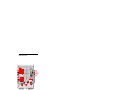
The Front Panel at a Glance
1 8V/20A range selection key (E3633A)
25V/7A range selection key (E3634A)
2 20V/10A range selection key (E3633A)
50V/4A range selection key (E3634A)
3 Overvoltage protection key
4 Overcurrent protection key
5 Display limit key
6 Recall operating state key
7
8
9
10
11
12
13
Store operating state/Local key
Error/Calibrate key
I/O Configuration/Secure key
Output On/Off key
Control knob
Resolution selection keys
Voltage/current adjust selection key
3
1 8V/20A* or 25V/7A** range selection key Selects the 8V/20A or 25V/7A
range and allows the full rated output to 8V/20A or 25V/7A.
2 20V/10A* or 50V/4A** range selection key Selects the 20V/10A or
50V/4A range and allows the full rated output to 20V/10A or 50V/4A.
3 Overvoltage protection key Enables or disables the overvoltage protection
function, sets trip voltage level, and clears the overvoltage condition.
4 Overcurrent protection key Enables or disables the overcurrent protection
function, sets trip current level, and clears the overcurrent condition.
5 Display limit key Shows voltage and current limit values on the display and
allows knob adjustment for setting limit values.
6 Recall operating state key Recalls a previously stored operating state from
location ‘‘1’’, ‘‘2’’, or ‘‘3’’.
7 Store operating state / Local key1 Stores an operating state in location ‘‘1’’,
‘‘2’’, or ‘‘3’’ / or returns the power supply to local mode from remote interface
mode.
8 Error / Calibrate key2 Displays error codes generated during operation, selftest and calibration / or enables calibration mode (the power supply must be
unsecured before performing calibration). See Service Guide for more details
on calibration.
9 I/O Configuration / Secure key3 Configures the power supply for remote
interfaces / or secure or unsecure the power supply for calibration. See
Service Guide for more details on how to secure or unsecure the power supply.
10 Output On/Off key Enables or disables the power supply output. This key
toggles between on and off.
11 Control knob Increases or decreases the value of the blinking digit by turning
clockwise or counter clockwise.
12 Resolution selection keys Move the blinking digit to the right or left.
13 Voltage/current adjust selection key Selects the knob control function for
voltage or current adjustment.
1The
key can be used as the ‘‘Local’’ key when the power supply is in the remote
interface mode.
2
You can enable the ‘‘calibration mode’’ by holding down this key when you turn on
the power supply.
3You can use it as the ‘‘Secure’’ or ‘‘Unsecure’’ key when the power supply is in the
calibration mode.
*For Agilent E3633A Model
4
**For Agilent E3634A Model
Front-Panel Voltage and Current Limit Settings
You can set the voltage and current limit values from the front panel using the
following method.
Use the voltage/current adjust selection key, the resolution selection keys,
and the control knob to change the voltage and current limit values.
1 Select the desired range using the range selection keys after turning on the
power supply.
2 Press the Display
key to show the limit values on the display.
Limit
3 Move the blinking digit to the appropriate position using the resolution
selection keys and change the blinking digit value to the desired voltage limit
by turning the control knob. If the display limit times out, press the Display
key
Limit
again.
Voltage
4 Set the knob to current control mode by pressing the Current
key.
5 Move the blinking digit to the appropriate position using the resolution
selection keys and change the blinking digit value to the desired current limit
by turning the control knob.
6 Press the Output
On/Off key to enable the output. After about 5 seconds, the display
will go to output monitoring mode automatically to display the voltage and
current at the output or the display will go to output monitoring mode
immediately by pressing the Display key again.
Limit
Note
All front panel keys and controls can be disabled with remote interface commands.
The Agilent E3633A and Agilent E3634A must be in "Local" mode for the front panel
keys and controls to function.
5
Display Annunciators
Adrs
Rmt
8V
20V
25V
50V
OVP
Power supply is addressed to listen or talk over a remote interface.
Power supply is in remote interface mode.
Shows the 8V/20A range is selected. (Agilent E3633A model)
Shows the 20V/10A range is selected. (Agilent E3633A model)
Shows the 25V/7A range is selected. (Agilent E3634A model)
Shows the 50V/4A range is selected. (Agilent E3634A model)
The overvoltage protection function is enabled when the
annunciator turns on or the overvoltage protection circuit has
caused the power supply to shutdown when the annunciator blinks.
OCP
The overcurrent protection function is enabled when the
annunciator turns on or the overcurrent protection circuit has
caused the power supply to shutdown when the annunciator blinks.
CAL
The power supply is in calibration mode.
Limit
The display shows the limit values of voltage and current.
ERROR Hardware or remote interface command errors are detected and
the error bit has not been cleared.
OFF
The output of the power supply is disabled (For more information,
see page 52 in the User’s Guide).
Unreg
The output of the power supply is unregulated (output is neither CV
nor CC).
CV
The power supply is in constant voltage mode.
CC
The power supply is in constant current mode.
To review the display annunciators, hold down
the power supply.
6
Display
Limit
key as you turn on
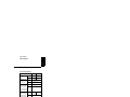
The Rear Panel at a Glance
1
2
3
4
Power-line voltage setting
Power-line fuse-holder assembly
AC inlet
Power-line module
5 GPIB (IEEE-488) interface connector
6 RS-232 interface connector
7 Rear output terminals
Use the front-panel I/O
Config key to:
• Select the GPIB or RS-232 interface (see chapter 3 in User’s Guide).
• Set the GPIB bus address (see chapter 3 in User’s Guide).
• Set the RS-232 baud rate and parity (see chapter 3 in User’s Guide).
7
In This Book
This is the Service Guide for your Agilent E3633A and E3634A DC power supplies.
Unless otherwise stated, the information in this manual applies to both two models.
Specifications Chapter 1 lists the power supply’s specifications and describes how
to interpret these specifications.
Quick Start Chapter 2 prepares the power supply for use and helps you get familiar
with the front panel features.
Calibration Procedures Chapter 3 provides performance verification and
calibration procedures.
Theory of Operation Chapter 4 describes block and circuit level theory related to
the operation of the power supply.
Service Chapter 5 provides guidelines for returning your power supply to Agilent
Technologies for servicing, or for servicing it yourself.
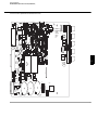
Component Drawings
drawings.
Chapter 6 contains the power supply’s component locator
If you have questions relating to the operation of the power supply, call
1-800-829-4444 in the United States, or contact your nearest Agilent
Technologies Sales Office.
If your Agilent E3633A or Agilent E3634A fails within 3 years of purchase,
Agilent will repair or replace it free of charge. Call 1-800-258-5165 ("Express
Exchange") in the United States, or contact your nearest Agilent Technologies
Sales Office.
8
Contents
Chapter 1 Specifications
Performance Specifications - - - - - - - - - - - - - - - - - - - - - - - - - - - - 15
Supplemental Characteristics- - - - - - - - - - - - - - - - - - - - - - - - - - - 17
Chapter 2 Quick Start
To Prepare the Power Supply for Use - - - - - - - - - - - - - - - - - - - - To Check the Rated Voltages of the Power Supply - - - - - - - - - - - To Check the Rated Currents of the Power Supply - - - - - - - - - - - To Use the Power Supply in Constant Voltage Mode - - - - - - - - - To Use the Power Supply in Constant Current Mode- - - - - - - - - - To Store and Recall the Instrument State - - - - - - - - - - - - - - - - - - To Program Overvoltage Protection - - - - - - - - - - - - - - - - - - - - - Setting the OVP Level and Enable the OVP Circuit - - - - - - - - Checking OVP Operation- - - - - - - - - - - - - - - - - - - - - - - - - - Clearing the Overvoltage Condition- - - - - - - - - - - - - - - - - - - To Program Overcurrent Protection - - - - - - - - - - - - - - - - - - - - - Setting the OCP Level and Enable the OCP Circuit - - - - - - - - Checking OCP Operation- - - - - - - - - - - - - - - - - - - - - - - - - - Clearing the Overcurrent Condition - - - - - - - - - - - - - - - - - - - To Rack Mount the Power Supply - - - - - - - - - - - - - - - - - - - - - - -
23
25
26
28
30
32
34
34
35
35
37
37
38
38
40
Chapter 3 Calibration Procedures
Agilent Technologies Calibration Services - - - - - - - - - - - - - - - - Calibration Interval - - - - - - - - - - - - - - - - - - - - - - - - - - - - - - - - Automating Calibration Procedures - - - - - - - - - - - - - - - - - - - - - Test Considerations - - - - - - - - - - - - - - - - - - - - - - - - - - - - - - - - Recommended Test Equipment - - - - - - - - - - - - - - - - - - - - - - - - Performance Verification Tests - - - - - - - - - - - - - - - - - - - - - - - - Self-Test - - - - - - - - - - - - - - - - - - - - - - - - - - - - - - - - - - - - - Performance Verification Tests - - - - - - - - - - - - - - - - - - - - - - Measurement Techniques - - - - - - - - - - - - - - - - - - - - - - - - - - - - Setup for Most Tests - - - - - - - - - - - - - - - - - - - - - - - - - - - - - Electronic Load - - - - - - - - - - - - - - - - - - - - - - - - - - - - - - - - General Measurement Techniques - - - - - - - - - - - - - - - - - - - - Current-Monitoring Resistor- - - - - - - - - - - - - - - - - - - - - - - - Programming - - - - - - - - - - - - - - - - - - - - - - - - - - - - - - - - - - Constant Voltage (CV) Verifications - - - - - - - - - - - - - - - - - - - - Constant Voltage Test Setup- - - - - - - - - - - - - - - - - - - - - - - - Voltage Programming and Readback Accuracy - - - - - - - - - - - -
45
45
45
46
47
48
48
48
49
49
49
50
50
50
51
51
51
9
CV Load Effect (Load Regulation) - - - - - - - - - - - - - - - - - - - CV Source effect (Line Regulation) - - - - - - - - - - - - - - - - - - CV PARD (Ripple and Noise) - - - - - - - - - - - - - - - - - - - - - - Load Transient Response Time- - - - - - - - - - - - - - - - - - - - - - Constant Current (CC) Verifications- - - - - - - - - - - - - - - - - - - - - Constant Current Test Setup- - - - - - - - - - - - - - - - - - - - - - - - Current Programming and Readback Accuracy - - - - - - - - - - - CC Load Effect (Load Regulation) - - - - - - - - - - - - - - - - - - - CC Source Effect (Line Regulation) - - - - - - - - - - - - - - - - - - CC PARD (Ripple and Noise) - - - - - - - - - - - - - - - - - - - - - - Common Mode Current Noise- - - - - - - - - - - - - - - - - - - - - - - - - Performance Test Record for Agilent E3633A and E3634A - - - - - CV Performance Test Record - - - - - - - - - - - - - - - - - - - - - - - CC Performance Test Record - - - - - - - - - - - - - - - - - - - - - - - Calibration Security Code- - - - - - - - - - - - - - - - - - - - - - - - - - - - To Unsecure the Power Supply for Calibration - - - - - - - - - - - To Unsecure the Power Supply Without the Security Code - - - Calibration Count - - - - - - - - - - - - - - - - - - - - - - - - - - - - - - - - - Calibration Message - - - - - - - - - - - - - - - - - - - - - - - - - - - - - - - General Calibration/Adjustment Procedure - - - - - - - - - - - - - - - - Front Panel Voltage and Current Calibration- - - - - - - - - - - - - Aborting a Calibration in Progress - - - - - - - - - - - - - - - - - - - - - - Calibration Record for Agilent E3633A/E3634A - - - - - - - - - - - - Error Messages - - - - - - - - - - - - - - - - - - - - - - - - - - - - - - - - - - - An Example program of Excel 97 for Calibration - - - - - - - - - - - - -
52
53
54
55
56
56
56
57
58
58
59
60
60
60
61
62
63
64
64
65
66
71
72
73
76
Chapter 4 Theory of Operation
Block Diagram Overview - - - - - - - - - - - - - - - - - - - - - - - - - - - - AC Input and Bias Supplies - - - - - - - - - - - - - - - - - - - - - - - - - - Floating Logic - - - - - - - - - - - - - - - - - - - - - - - - - - - - - - - - - - - D-to-A Converter - - - - - - - - - - - - - - - - - - - - - - - - - - - - - - - - - A-to-D Converter - - - - - - - - - - - - - - - - - - - - - - - - - - - - - - - - - Power Mesh and Control - - - - - - - - - - - - - - - - - - - - - - - - - - - - Earth-Referenced Logic - - - - - - - - - - - - - - - - - - - - - - - - - - - - - Front Panel- - - - - - - - - - - - - - - - - - - - - - - - - - - - - - - - - - - - - - -
87
89
90
92
93
94
96
96
Chapter 5 Service
Operating Checklist - - - - - - - - - - - - - - - - - - - - - - - - - - - - - - - - - 99
Is the Power Supply Inoperative? - - - - - - - - - - - - - - - - - - - - - 99
Does the Power Supply Fail Self-Test? - - - - - - - - - - - - - - - - - 99
Types of Service Available - - - - - - - - - - - - - - - - - - - - - - - - - - - 100
Standard Repair Service (worldwide) - - - - - - - - - - - - - - - - - 100
10
Express Exchange (U.S.A. only) - - - - - - - - - - - - - - - - - - - - Repacking for Shipment - - - - - - - - - - - - - - - - - - - - - - - - - - - - Electrostatic Discharge (ESD) Precautions- - - - - - - - - - - - - - - - Surface Mount Repair - - - - - - - - - - - - - - - - - - - - - - - - - - - - - To Replace the Power-Line Fuse - - - - - - - - - - - - - - - - - - - - - - To Disconnect the Output Using an External Relay - - - - - - - - - - Installation Procedure - - - - - - - - - - - - - - - - - - - - - - - - - - - Troubleshooting Hints - - - - - - - - - - - - - - - - - - - - - - - - - - - - - Unit is Inoperative - - - - - - - - - - - - - - - - - - - - - - - - - - - - - Unit Reports Errors 740 to 750 - - - - - - - - - - - - - - - - - - - - - Unit Fails Self-Test - - - - - - - - - - - - - - - - - - - - - - - - - - - - - Bias Supplies Problems - - - - - - - - - - - - - - - - - - - - - - - - - - Self-Test Procedures - - - - - - - - - - - - - - - - - - - - - - - - - - - - - - Power-On Self-Test - - - - - - - - - - - - - - - - - - - - - - - - - - - - Complete Self-Test - - - - - - - - - - - - - - - - - - - - - - - - - - - - - -
100
101
102
102
102
103
103
104
104
104
104
105
106
106
106
Chapter 6 Component Drawings
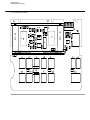
E3633-60002/E3634-60002 Component locator for the main board 111
E3633-60003 Component locator for the front panel - - - - - - - - - - 112
E3633-60019/E3634-60019 Component locator for the main board (serial MY53xx6xxx)
113
Component locator for the front panel (serial MY53xx6xxx) - - - - 114
11
THIS PAGE HAS BEEN INTENTIONALLY LEFT BLANK.
12
1
Specifications
Specifications
The performance specifications are listed in the following pages. Specifications are
warranted in the temperature range of 0 to 40°C with a resistive load. Supplemental
characteristics, which are not warranted but
are descriptions of performance determined either by design or testing. Chapter 3
‘‘Calibration Procedures’’ contains procedures for verifying the performance
specifications.
14
Chapter 1 Specifications
Performance Specifications
1
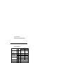
Performance Specifications
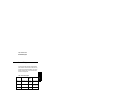
Table 1-1. Performance Specifications
Parameter
Output Ratings
(@ 0 °C - 40 °C)
Accuracy[1]
Programming
12 months (@ 25 °C ± 5 °C),
±(% of output + offset)
Agilent E3633A
Agilent E3634A
Low Range
0 to +8 V/0 to 20 A
0 to +25 V/0 to 7 A
High Range
0 to +20 V/0 to 10 A 0 to +50V/0 to 4 A
Voltage
0.05% + 10 mV
Current
0.2% + 10 mA
Readback Accuracy[1] [2] Voltage
12 months (over GPIB and
Current
RS-232 or front panel with
respect to actual output @ 25 °C
± 5 °C), ±(% of output + offset)
0.05% + 5 mV
Ripple and Noise
(with outputs ungrounded, or
with either output terminal
grounded, 20 Hz to 20 MHz)
Normal mode
voltage
0.15% + 5 mA
<0.35 mV rms and
3 mV p-p
<0.5 mV rms and
3 mV p-p
Normal mode
current
<2 mA rms
Common mode
current
<1.5 uA rms
Load Regulation,
±(% of output + offset)
Voltage
<0.01% + 2 mV
Current
<0.01% + 250 uA
Line Regulation,
±(% of output + offset)
Voltage
<0.01% + 2 mV
Current
<0.01% + 250 uA
Programming Resolution
Voltage
1 mV
3 mV
Current
1 mA
0.5 mA
Voltage
0.5 mV
1.5 mV
Current
1 mA
0.5 mA
Readback Resolution
Front Panel Resolution
Voltage
Current
1 mV
1 mA (< 10A), 10mA (≥ 10A)
[1]
Accuracy specifications are after an 1-hour warm-up with no load and
calibration at 25 °C.
[2]
This specification may degrade when the unit is subjected to an RF field
>= 3V/meter.
15
Chapter 1 Specifications
Performance Specifications
Transient Response Time
Less than 50 μsec for output to recover to within 15 mV following a change in output
current from full load to half load or vice versa
Command Processing Time
Average time for output voltage to begin to change after receipt of digital data when
the power supply is connected directly to the GPIB or RS-232 is less than 100 msec
OVP and OCP Accuracy, ±(% of output + offset)
OVP
OCP
0.5% + 0.5 V
0.5% + 0.5 A
Activation time : Average time for output to start to drop after OVP or OCP
OVP
OCP
16
condition occurs.
<1.5 msec when the trip voltage is equal or greater than 3 V
<10 msec when the trip voltage is less than 3 V
<10 msec
Chapter 1 Specifications
Supplemental Characteristics
1
Supplemental Characteristics
Table 1-2. Supplemental Characteristics
Parameter
Agilent E3633A
Agilent E3634A
Output Programming Range Low Range
(maximum programmable values)
0 to +8.24 V/
0 to 20.6 A
0 to +25.75 V/
0 to 7.21 A
High Range
0 to +20.6 V/
0 to 10.3 A
0 to +51.5V/
0 to 4.12 A
OVP
1 V to 22 V
1 V to 55 V
OCP
0 A to 22 A
0 A to 7.5 A
Voltage Programming
Speed: Maximum time required
Up
for output voltage to settle within
1% of its total excursion (for
Down
resistive load). Excludes
command processing time.
Full Load No Load Full Load No Load
95 msec
45 msec
80 msec
100 msec
30 msec
450 msec 30 msec
450 msec
Remote Sensing Capability
Voltage drop
Load regulation
Load voltage
Up to 0.7 V per each lead
Add 5 mV to spec for each 1-volt change in the + output
lead due to load current changes.
Subtract voltage drop in load leads from specified output
voltage rating.
Temperature Coefficient, ±(% of output + offset)
Maximum change in output/readback per °C after a 30-minute warm-up
Voltage
0.01% + 3 mV
Current
0.02% + 3 mA
Stability, ±(% of output + offset)
Following a 30-minute warm-up, with the output in the ON state according to the
operating mode (CC with load or CV), and with a change in the output over 8 hours
under constant load, line, and ambient temperature
Voltage
0.02% + 1 mV
Current
0.1% + 1 mA
17
Chapter 1 Specifications
Supplemental Characteristics
Output Voltage Overshoot
During turn-on or turn-off of ac power, output plus overshoot will not exceed 1 V if
the output control is set to less than 1 V. If the output control is set to
1 V or higher, there is no overshoot.
Programming Language
SCPI (Standard Commands for Programmable Instruments)
State Storage Memory
Three (3) user-configurable stored states
Recommended Calibration Interval
1 year
Output Terminal Isolation (maximum, from chassis ground)
±60 Vdc when connecting shorting conductors without insulation to the
(+) output to the (+) sense and the (-) output and the (-) sense terminals.
±240 Vdc when connecting insulated shorting conductors to the (+) output
to the (+) sense and the (-) output and the (-) sense terminals.
AC Input Ratings (selectable via rear panel selector)
std
opt 0E3
opt 0E9
115 Vac ± 10%, 47 to 63 Hz
230 Vac ± 10%, 47 to 63 Hz
100 Vac ± 10%, 47 to 63 Hz
Maximum Input Power
700 VA with full load
Cooling
Fan cooled
Operating Temperature
0 to 40 °C for full rated output. At higher temperatures, the output current is derated
linearly to 50% at 55 °C maximum temperature.
18
Chapter 1 Specifications
Supplemental Characteristics
1
Storage Temperature
-20 to 70 °C for storage environment.
Environmental Conditions
Designed for indoor use in an installation category II, pollution degree 2 environment.
Designed to operate at a maximum relative humidity of 95 %
and at altitudes of up to 2000 meters.
Dimensions*
213 mmW x 133 mmH x 348 mmD (8.4 x 5.2 x 13.7 in)
*See below for detailed information.
Weight
Net
Shipping
9.5 kg (21 lb)
12 kg (26 lb)
Weight (MY53xx6xxx)
Net
Shipping
11.4 kg (E3633A)
10.9 kg (E3634A)
13.9 kg (E3633A)
13.4 kg (E3634A)
19
Chapter 1 Specifications
Supplemental Characteristics
Figure 8-1. Dimensions of Agilent E3633A and E3634A Power Supplies
20
2
Quick Start
Quick Start
One of the first things you will want to do with your power supply is to become
acquainted with its front panel. Written procedures in this chapter prepare the power
supply for use and familiarize you with most front-panel operations.
• The power supply is shipped from the factory configured in the front-panel
operation mode. At power-on, the power supply is automatically set to operate in
the front-panel operation mode. When in this mode, the front-panel keys can be
used. When the power supply is in remote operation mode, you can return to frontStore
panel operation mode at any time by pressing the Local (Local) key if you did not
previously send the front-panel lockout command. A change between front-panel
and remote operation modes will not result in a change in the output parameters.
• The power supply has two output ranges. This feature allows more voltage at a
lower current or more current at a lower voltage. The desired output range is
selected from the front panel or over the remote interfaces. The 8V or 20V for the
E3633A and 25V or 50V for the E3634A annunciator indicates the presently
selected range.
• When you press Display
key (the Limit annunciator flashes), the display of the power
Limit
supply goes to the limit mode and the present limit values will be displayed. In this
mode, you can also observe the change of the limit values when adjusting the knob.
If you press the Display
key again or let the display time-out after several seconds,
Limit
the power supply will return the display to the meter mode (the Limit annunciator
turns off). In this mode, the actual output voltage and current will be displayed.
• The output of the power supply can be enabled or disabled from the front panel by
pressing Output
On/Off key. When the output is off, the OFF annunciator turns on and the
output is disabled.
• The display provides the present operating status of the power supply with
annunciators and also informs the user of error codes. For example, the power
supply is operating in CV mode in the 8V/20A* or 25V/7A** range and controlled
from the front panel, then the CV and 8V* or 25V** annunciators will turn on. If,
however, the power supply is remotely controlled, the Rmt annunciator will also
turn on, and when the power supply is being addressed over GPIB interface, the
Adrs annunciator will turn on. See “Display Annunciators’’ on page 5 for more
information.
*For Agilent E3633A Model
22
**For Agilent E3634A Model
Chapter 2 Quick Start
To Prepare the Power Supply for Use
To Prepare the Power Supply for Use
The following steps help you verify that the power supply is ready for use.
1 Check the list of supplied items.
Verify that you have received the following items with your power supply. If anything
is missing, contact your nearest Agilent Technologies Sales Office.
One power cord for your location.
One User’s Guide.
This Service Guide.
Certificate of Calibration.
2 Verify that the correct power-line voltage setting is selected and that the correct
power-line fuse is installed.
The line voltage is set to 100, 115 or 230 Vac from the factory according to the input
power option selected when you ordered the power supply. Change the voltage setting
if it is not correct for your location (see the next page for detailed information). For
100 or 115 Vac operation, the correct fuse is 6.3 AT (Agilent part number 2110-1030)
and for 230 Vac operation, the correct fuse is
3.15 AT (Agilent part number 2110-1031).
Power
3 Connect the power cord and turn on the power supply.
A power-on self-test occurs automatically when you turn on the power supply. The
front-panel display will light up while the power supply performs its power-on selftest. After performing the self-test, the power supply will go into the power-on / reset
state; the output is disabled (the OFF annunciator turns on); the 8V/20A* or 25V/
7A** range is selected (the 8V* or 25V** annunciator turns on); the knob is selected
for voltage control.
Notice that the OVP and OCP annunciators also turn on.
Output
On/Off
4 Enable the outputs.
Press Output
On/Off key to enable the outputs. The OFF annunciator turns off and the 8V* or
25V**, OVP, OCP, and CV annunciators are lit. The flashing digit can be adjusted by
turning the knob. Notice that the display is in the meter mode. ‘‘Meter mode’’ means
that the display shows the actual output voltage and current.
*For Agilent E3633A Model
**For Agilent E3634A Model
23
2
Chapter 2 Quick Start
To Prepare the Power Supply for Use
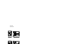
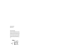
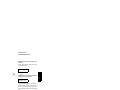
1 Remove the power cord. Remove the
fuse-holder assembly with a flat-blade
screwdriver from the rear panel.
2 Install the correct line fuse. Remove
the power-line voltage selector from the
power-line module.
100 or 115 Vac, 6.3 AT fuse
230 Vac, 3.15 AT fuse
3 Rotate the power-line voltage selector
until the correct voltage appears.
4 Replace the power-line voltage selector
and the fuse-holder assembly in the rear
panel.
100, 115, or 230 Vac
Install the correct fuse and verify that the correct line voltage appears in the
window.
24
Chapter 2 Quick Start
To Check the Rated Voltages of the Power Supply
To Check the Rated Voltages of the Power Supply
The following procedures check to ensure that the power supply produces its rated
voltage output with no load and properly responds to operation from the front panel.
For each step, use the keys shown on the left margins.
Power
1 Turn on the power supply.
The power supply will go into the power-on / reset state; the output is disabled (the
OFF annunciator turns on); the 8V/20A* or 25V/7A** range is selected (the 8V* or
25V** annunciator turns on); and the knob is selected for voltage control.
Output
On/Off
2 Enable the outputs.
The OFF annunciator turns off and the 8V* or 25V**, OVP, OCP, and CV annunciators
are lit. The flashing digit can be adjusted by turning the knob. Notice that the display
is in the meter mode. “Meter mode’’ means that the display shows the actual output
voltage and current.
3 Check that the front-panel voltmeter properly responds to knob control.
Turn the knob clockwise or counter clockwise to check that the voltmeter responds
to knob control and the ammeter indicates nearly zero.
1
4 Ensure that the voltage can be adjusted from zero to the maximum rated value.
Adjust the knob until the voltmeter indicates 0 volts and then adjust the knob until
the voltmeter indicates ‘‘8.0 volts’’* or ‘‘25.0 volts’’**.
1
You can use the resolution selection keys to move the flashing digit to the right or
left when setting the voltage.
*For Agilent E3633A Model
**For Agilent E3634A Model
25
2
Chapter 2 Quick Start
To Check the Rated Currents of the Power Supply
To Check the Rated Currents of the Power Supply
The following procedures check to ensure that the power supply produces its rated
current outputs with a short and properly responds to operation from the front panel.
For each step, use the keys shown on the left margins.
Power
1 Turn on the power supply.
The power supply will go into the power-on / reset state; the output is disabled (the
OFF annunciator turns on); the 8V/20A* or 25V/7A** range is selected (the 8V* or
25V** annunciator turns on); and the knob is selected for voltage control.
2 Connect a short across (+) and (-) output terminals with an insulated test lead.
Output
On/Off
Display
Limit
Voltage
Current
3 Enable the outputs.
The OFF annunciator turns off and the 8V* or 25V**, OVP, and OCP annunciators
turn on. The CV or CC annunciator is lit depending on the resistance of the test lead.
The flashing digit can be adjusted by turning the knob. Notice that the display is in
the meter mode. “Meter mode’’ means that the display shows the actual output voltage
and current.
4 Adjust the voltage limit value to 1.0 volt.
Set the display to the limit mode (the Limit annunciator will be flashing). Adjust the
voltage limit to 1.0 volt to assure CC operation. The CC annunciator will light.
5 Check that the front-panel ammeter properly responds to knob control.
Set the knob to the current control, and turn the knob clockwise or counter clockwise
when the display is in the meter mode (the Limit annunciator is off). Check that the
ammeter responds to knob control and the voltmeter indicates nearly zero (actually,
the voltmeter will show the voltage drop caused by the test lead).
*For Agilent E3633A Model
26
**For Agilent E3634A Model
Chapter 2 Quick Start
To Check the Rated Currents of the Power Supply
1
6 Ensure that the current can be adjusted from zero to the maximum rated value.
Adjust the knob until the ammeter indicates 0 amps and then until the ammeter
indicates ‘‘20.0 amps’’* or ‘‘7.0 amps’’**.
Note
If an error has been detected during the output checkout procedures, the ERROR
annunciator will turn on. See “Error Messages’’ for more information, starting on
page 123 in chapter 5 of the User’s Guide.
1
You can use the resolution selection keys to move the flashing digit to the right or
left when setting the voltage.
*For Agilent E3633A Model
**For Agilent E3634A Model
27
2
Chapter 2 Quick Start
To Use the Power Supply in Constant Voltage Mode
To Use the Power Supply in Constant Voltage Mode
To set up the power supply for constant voltage (CV) operation, proceed as follows.
For each step, use the keys shown on the left margin.
1 Connect a load to the desired output terminals.
With power-off, connect a load to the desired output terminals.
Power
2 Turn on the power supply.
The power supply will go into the power-on / reset state; the output is disabled (the
OFF annunciator turns on); the 8V/20A* or 25V/7A** range is selected (the 8V* or
25V** annunciator turns on); and the knob is selected for voltage control.
Press 20V,10A * or 50V,4A ** key to operate the power supply in the 20V/10A* or 50V/
4A** range before proceeding to the next step. The 20V* or 50V** annunciator turns
on.
Display
Limit
3 Set the display to the limit mode.
Notice that the Limit annunciator flashes, indicating that the display is in the limit
mode. When the display is in the limit mode, you can see the voltage and current limit
values of the power supply.
In constant voltage mode, the voltage values between the meter and limit modes
are the same, but the current values are not. Moreover, if the display is in the
meter mode, you cannot see the change of current limit value when adjusting the
knob. We recommend that you should set the display to “limit” mode to see the
change of current limit value in the constant voltage mode whenever adjusting the
knob.
Voltage
Current
1
4 Adjust the knob for the desired current limit.
Check that the Limit annunciator still flashes. Set the knob for current control. The
second digit of the ammeter will be flashing. The flashing digit can be changed using
the resolution selection keys and the flashing digit can be adjusted by turning the knob.
Adjust the knob to the desired current limit.
1
You can use the resolution selection keys to move the flashing digit to the right or
left when setting current.
*For Agilent E3633A Model
28
**For Agilent E3634A Model
Chapter 2 Quick Start
To Use the Power Supply in Constant Voltage Mode
Voltage
Current
Display
Limit
Output
On/Off
1
5 Adjust the knob for the desired output voltage.
Check that the Limit annunciator still flashes. Set the knob for voltage control. The
second digit of the voltmeter will be flashing. Change the flashing digit using the
resolution selection keys and adjust the knob to the desired output voltage.
6 Return to the meter mode.
Press Display
key or let the display time-out after several seconds to return to the meter
Limit
mode. Notice that the Limit annunciator turns off and the display shows “OUTPUT
OFF” message.
7 Enable the output.
The OFF annunciator turns off and the 8V* (or 25V**) or 20V* (or 50V**), OVP, OCP
and CV annunciators are lit. Notice that the display is in the meter mode. In the meter
mode, the display shows the actual output voltage and current.
8 Verify that the power supply is in the constant voltage mode.
If you operate the power supply in the constant voltage (CV) mode, verify that the
CV annunciator is lit. If the CC annunciator is lit, choose a higher current limit.
Note
During actual CV operation, if a load change causes the current limit to be exceeded,
the power supply will automatically crossover to the constant current mode at the
preset current limit and the output voltage will drop proportionately.
1
You can use the resolution selection keys to move the flashing digit to the right or
left when setting the current.
*For Agilent E3633A Model
**For Agilent E3634A Model
29
2
Chapter 2 Quick Start
To Use the Power Supply in Constant Current Mode
To Use the Power Supply in Constant Current Mode
To set up the power supply for constant current (CC) operation, proceed as follows.
1 Connect a load to the output terminals.
With power-off, connect a load to the (+) and (-) output terminals.
Power
2 Turn on the power supply.
The power supply will go into the power-on / reset state; the output is disabled (the
OFF annunciator turns on); the 8V/20A* or 25V/7A** range is selected (the 8V* or
25V** annunciator turns on); and the knob is selected for voltage control.
Press 20V,10A * or 50V,4A ** key to operate the power supply in the 20V/10A* or 50V/
4A** range before proceeding to the next step. The 20V* or 50V** annunciator turns
on.
Display
Limit
3 Set the display to the limit mode.
Notice that the Limit annunciator flashes, indicating that the display is in the limit
mode. When the display is in the limit mode, you can see the voltage and current limit
values of the selected supply.
In constant current mode, the current values between the meter mode and limit
mode are the same, but the voltage values are not. Moreover, if the display is in
the meter mode, you cannot see the change of voltage limit value when adjusting
the knob. We recommend that you should set the display to “limit” mode to see
the change of voltage limit value in the constant current mode whenever adjusting
the knob.
1
4 Adjust the knob for the desired voltage limit.
Check that the Limit annunciator still flashes and the second digit of voltmeter flashes
to indicate the knob is selected for voltage control. The flashing digit can be changed
using the resolution keys and the flashing digit can be adjusted by turning the knob.
Adjust the knob for the desired voltage limit.
1
You can use the resolution selection keys to move the flashing digit to the right or
left when setting the voltage.
*For Agilent E3633A Model
30
**For Agilent E3634A Model
Chapter 2 Quick Start
To Use the Power Supply in Constant Current Mode
Voltage
Current
Display
Limit
Output
On/Off
1
5 Adjust the knob for the desired output current.
Check that the Limit annunciator still flashes. Set the knob for current control. The
second digit of the ammeter will be flashing. Change the flashing digit using the
resolution selection keys and adjust the knob to the desired output current.
6 Return to the meter mode.
Press Display
key or let the display time-out after several seconds to return to the meter
Limit
mode. Notice that the Limit annunciator turns off and the display shows “OUTPUT
OFF” message.
7 Enable the output.
The OFF annunciator turns off and the 8V* (or 25V**) or 20V* (or 50V**), OVP, OCP
and CC annunciators are lit. Notice that the display is in the meter mode. In the meter
mode, the display shows the actual output voltage and current.
8 Verify that the power supply is in the constant current mode.
If you operate the power supply in the constant current (CC) mode, verify that the CC
annunciator is lit. If the CV annunciator is lit, choose a higher voltage limit.
Note
During actual CC operation, if a load change causes the voltage limit to be exceeded,
the power supply will automatically crossover to constant voltage mode at the preset
voltage limit and the output current will drop proportionately.
1
You can use the resolution selection keys to move the flashing digit to the right or
left when setting the voltage.
*For Agilent E3633A Model
**For Agilent E3634A Model
31
2
Chapter 2 Quick Start
To Store and Recall the Instrument State
To Store and Recall the Instrument State
You can store up to three different operating states in non-volatile memory. This also
enables you to recall the entire instrument configuration with just a few key presses
from the front panel.
The memory locations are supplied with the reset states from the factory for frontpanel operation. Refer to the description of *RST command, starting on page 96 in
the User’s Guide for more information.
The following steps show you how to store and recall an operating state.
1 Set up the power supply for the desired operating state.
The storage feature “remembers” output range selection, the limit value settings of
voltage and current, output on/off state, OVP and OCP on/off state, and OVP and
OCP trip levels.
Store
2 Turn on the storage mode.
Three memory locations (numbered 1, 2 and 3) are available to store the operating
states. The operating states are stored in non-volatile memory and are remembered
when being recalled.
STORE 1
This message appears on the display for approximately 3 seconds.
3 Store the operating state in memory location “3”.
Turn the knob to the right to specify the memory location 3.
STORE 3
To cancel the store operation, let the display time-out after about 3 seconds or press
any other function key except the Store key. The power supply returns to the normal
operating mode and to the function pressed.
32
Chapter 2 Quick Start
To Store and Recall the Instrument State
Store
4 Save the operating state.
The operating state is now stored. To recall the stored state, go to the following steps.
2
DONE
Recall
5 Turn on the recall mode.
Memory location “1” will be displayed in the recall mode.
RECALL 1
This message appears on the display for approximately 3 seconds.
6 Recall the stored operating state.
Turn the knob to the right to change the displayed storage location to 3.
RECALL 3
If this setting is not followed within 3 seconds with Recall key stroke, the power
supply returns to normal operating mode and will not recall the instrument state 3
from memory.
Recall
7 Restore the operating state.
The power supply should now be configured in the same state as when you stored the
state on the previous steps.
DONE
This message appears on the display for approximately 1 second.
33
Chapter 2 Quick Start
To Program Overvoltage Protection
To Program Overvoltage Protection
Overvoltage protection guards the load against output voltages that reach a specified
value greater than the programmed protection level. It is accomplished by shorting
the output via an internal SCR when the trip level is set to equal or greater than 3
volts, or by programming the output to 1 volt when the trip level is set to less than 3
volts.
The following steps show how to set the OVP trip level, how to check OVP operation,
and how to clear overvoltage condition.
Setting the OVP Level and Enable the OVP Circuit
Power
1 Turn on the power supply.
The power supply will go into the power-on / reset state; the output is disabled (the
OFF annunciator turns on); the 8V/20A* or 25V/7A** range is selected (the 8V* or
25V** annunciator turns on); and the knob is selected for voltage control.
Output
On/Off
Over
Voltage
2 Enable the output.
The OFF annunciator turns off and the display will go to the meter mode.
3 Enter the OVP menu and set the trip level.
LEVEL 22.0 V (E3633A)
LEVEL 55.0 V (E3634A)
You will see the above message on the display when you enter the OVP menu. Adjust
the control knob for the desired OVP trip level.
Note that you cannot set the trip levels to lower than 1.0 volt.
Over
Voltage
4 Enable the OVP circuit.
OVP ON
You will see the above message after pressing
*For Agilent E3633A Model
34
Over
Voltage
key.
**For Agilent E3634A Model
Chapter 2 Quick Start
To Program Overvoltage Protection
Over
Voltage
5 Exit the OVP menu.
CHANGED
The “CHANGED” message is highlighted for a second to show that the new OVP
trip level is now in effect. If the OVP settings are not changed, “NO CHANGE” will
be displayed. The power supply will exit the OVP menu and the display will return
to the meter mode. Check that the OVP annunciator turns on.
Checking OVP Operation
To check OVP operation, raise the output voltage to near the trip point. Then very
gradually increase the output by turning the knob until the OVP circuit trips. This will
cause the power supply output to drop to near zero, the OVP annunciator to blink, and
the CC annunciator to turn on. The “OVP TRIPPED” message also appears on the
display.
Clearing the Overvoltage Condition
When the OVP condition occurs (the “OVP TRIPPED” message is shown on the
display), the OVP annunciator flashes. When it was caused by an external voltage
source such as a battery, disconnect it first. Clear the overvoltage condition by
adjusting output voltage level or by adjusting OVP trip level.
The following steps show how to clear the overvoltage condition and get back to
normal mode operation. In the following steps, the display will go back to “OVP
TRIPPED” if you let the display time out after about several seconds.
• Adjust output voltage level
Display
Limit
Over
Voltage
1 Lower the output voltage level.
Lower the output voltage level below the OVP trip point after pressing
The OVP and Limit annunciators are blinking.
Display
Limit
key.
2 Move to the clear mode.
OVP CLEAR
Press Over
Voltage key twice to move to the OVP CLEAR mode. The “OVP ON” message
appears on the display. Turn the knob to the right until the above message appears on
the display.
35
2
Chapter 2 Quick Start
To Program Overvoltage Protection
Over
Voltage
3 Clear the overvoltage condition and exit this menu.
Now, when you press Over
Voltage key again, the “DONE” message is displayed for a second
and the OVP annunciator will not blink any more. The output will return to meter
mode.
• Adjust OVP trip level
Over
Voltage
Over
Voltage
1 Raise the OVP trip level.
Press Over
Voltage key and turn the knob to raise the OVP trip level.
2 Move to the OVP CLEAR mode.
OVP CLEAR
Press Over
Voltage key to move to the OVP CLEAR mode. The “OVP ON” message appears
on the display. Turn the knob to the right until the above message appears on the
display.
Over
Voltage
3 Clear the overvoltage condition and exit this menu.
Now, when you press Over
Voltage key again, the “DONE’’ message is displayed for a
second and the OVP annunciator will not blink any more. The output will return to
the meter mode.
36
Chapter 2 Quick Start
To Program Overcurrent Protection
To Program Overcurrent Protection
Overcurrent protection guards the load against output currents that reach a specified
value greater than the programmed protection level. It is accomplished by
programming the output current to zero.
The following steps show how to set the overcurrent protection trip level, how to
check OCP operation and how to clear overcurrent condition.
Setting the OCP Level and Enable the OCP Circuit
Power
1 Turn on the power supply.
The power supply will go into the power-on / reset state; the output is disabled (the
OFF annunciator turns on); the 8V/20A* or 25V/7A** range is selected (the 8V* or
25V** annunciator turns on); and the knob is selected for voltage control.
Output
On/Off
Over
Current
2 Enable the output.
The OFF annunciator turns off and the display will go to the meter mode.
3 Enter the OCP menu and set the trip level.
LEVEL 22.0 A (E3633A)
LEVEL 7.5 A (E3634A)
You will see the above message on the display when you enter the OCP menu. Adjust
the knob for the desired OCP trip level.
Over
Current
4 Enable the OCP circuit.
OCP ON
You will see the above message after pressing the
*For Agilent E3633A Model
Over
Current
key.
**For Agilent E3634A Model
37
2
Chapter 2 Quick Start
To Program Overcurrent Protection
Over
Current
5 Exit the OCP menu.
CHANGED
The “CHANGED” message is displayed for a second to show that the new OCP trip
level is now in effect. If the OCP settings are not changed, “NO CHANGE” will be
displayed. The power supply will exit the OCP menu and the display will return to
the meter mode. Check that the OCP annunciator turns on.
Checking OCP Operation
To check OCP operation, raise the output current to near the trip point. Then very
gradually increase the output by turning the knob until the OCP circuit trips. This will
cause the power supply’s output current to drop to zero and the OCP annunciator to
blink. The “OCP TRIPPED” message also appears on the display.
Clearing the Overcurrent Condition
When the OCP condition occurs (the “OCP TRIPPED” message is shown on the
display), the OCP annunciator flashes. When it was caused by external voltage sources
such as a battery, disconnect it first. Clear the overcurrent condition by adjusting
output current level or by adjusting OCP trip level.
The following steps show how to clear the overcurrent condition and get back to
normal mode operation. In the following steps, the display will go back to “OCP
TRIPPED” if you let the display time out after about several seconds.
• Adjust output current level
Display
Limit
Over
Current
1 Lower the output current level.
Press Display
key and set the knob for current control by pressing
Limit
lower the output current level below the OCP trip point.
Voltage
Current
key, then
2 Move to the clear mode.
OCP CLEAR
Press Over
Current key twice to move to the OCP CLEAR mode. The “OCP ON” message
appears on the display. Turn the knob to the right until the above message appears on
the display.
38
Chapter 2 Quick Start
To Program Overcurrent Protection
Over
Current
3 Clear the overcurrent condition and exit this menu.
Now, when you press Over
Current key again, the “DONE’’ message is displayed for a
second and the OCP annunciator will not blink any more. The output will return to
meter mode. The knob is selected for current control.
Notice that the power supply is operated in the constant current (CC) mode.
• Adjust OCP trip level
Over
Current
Over
Current
1 Raise the OCP trip level.
Press Over
Current key and turn the knob to raise the OCP trip level.
2 Move to the OCP CLEAR mode.
OCP CLEAR
Press the Over
Current key to move to the OCP CLEAR mode. The “OCP ON” message
appears on the display. Turn the knob to the right until the above message appears on
the display.
Over
Current
3 Clear the overcurrent condition and exit this menu.
Now, when you press Over
Current key again, the “DONE’’ message is displayed for a
second and the OCP annunciator will not blink any more. The output will return to
the meter mode.
39
2
Chapter 2 Quick Start
To Rack Mount the Power Supply
To Rack Mount the Power Supply
The power supply can be mounted in a standard 19-inch rack cabinet using one of
three optional kits available. A rack-mounting kit for a single instrument is available
as Option 1CM (P/N 5063-9243). Installation instructions and hardware are included
with each rack-mounting kit. Any Agilent System II instrument of the same size can
be rack-mounted beside the Agilent E3633A or E3634A DC power supply.
Remove the front and rear bumpers before rack-mounting the power supply.
To remove the rubber bumper, pull the bumper off from the top as there
are protrusions on the sides and bottom of the cover.
To rack mount a single instrument, order adapter kit 5063-9243.
40
Chapter 2 Quick Start
To Rack Mount the Power Supply
2
To rack mount two instruments of the same depth side-by-side, order
lock-link kit 5061-9694 and flange kit 5063-9214.
To install two instruments in a sliding support shelf, order support shelf
5063-9256, and slide kit 1494-0015.
41
Chapter 2 Quick Start
To Rack Mount the Power Supply
THIS PAGE HAS BEEN INTENTIONALLY LEFT BLANK.
42
3
Calibration Procedures
Calibration Procedures
This chapter contains procedures for verification of the power supply’s performance
and calibration (adjustment). The chapter is divided into the following sections:
•
•
•
•
•
•
•
•
•
•
•
•
•
•
•
•
•
•
•
Agilent Technologies Calibration Services, on page 45
Calibration Interval, on page 45
Automating Calibration Procedures, on page 46
Test Considerations, on page 46
Recommended Test Equipment, on page 47
Performance Verification Tests, on page 48
Measurement Techniques, starting on page 49
Constant Voltage (CV) Verifications, starting on page 51
Constant Current (CC) Verifications, starting on page 56
Common Mode Current Noise, on page 59
Performance Test Record for Agilent E3633A/E3634A, on page 60
Calibration Security Code, starting on page 61
Calibration Count, on page 64
Calibration Message, on page 64
General Calibration/Adjustment Procedure, starting on page 65
Aborting a Calibration in Progress, on page 71
Calibration Record for Agilent E3633A/E3634A, on page 72
Error Messages, starting on page 73
An Example Program of Excel 97 for Calibration, starting on page 75
The performance verification tests for constant voltage (CV) and constant current
(CC) operations use the power supply’s specifications listed in
chapter 1, ‘‘Specifications,’’ starting on page 13.
44
Chapter 3 Calibration Procedures
Agilent Technologies Calibration Services
Note
If you calibrate the power supply over the remote interface, you must send the *RST
command to the power supply or turn the power supply off and on again after
performing a calibration to ensure proper power supply operation.
Closed-Case Electronic Calibration The power supply features closed-case
electronic calibration since no internal mechanical adjustments are required for
normal calibration. The power supply calculates correction factors based upon the
input reference value you enter. The new correction factors are stored in non-volatile
memory until the next calibration adjustment is performed. (Non-volatile memory
does not change when power has been off or after a remote interface reset.)
Agilent Technologies Calibration Services
When your power supply is due for calibration, contact your local Agilent
Technologies Service Center for a low-cost calibration. The Agilent E3633A and
E3634A power supplies are supported on calibration processes which allow Agilent
Technologies to provide this service at competitive prices.
Calibration Interval
The power supply should be calibrated on a regular interval determined by the
accuracy requirements of your application. A 1-year interval is adequate for most
applications. Agilent Technologies does not recommend extending calibration
intervals beyond 1 year for any application. Agilent Technologies recommends that
complete re-adjustment should always be performed at the calibration interval. This
will increase your confidence that the Agilent E3633A and E3634A will remain within
specification for the next calibration interval. This criteria for re-adjustment provides
the best long-term stability.
Automating Calibration Procedures
You can automate the complete verification procedures outlined in this chapter if you
have access to programmable test equipment. You can program the instrument
configurations specified for each test over the remote interface. You can then enter
readback verification data into a test program and compare the results to the
appropriate test limit values.
45
3
Chapter 3 Calibration Procedures
Test Considerations
You can also enter calibration constants from the remote interface. Remote operation
is similar to the local front-panel procedure. You can use a computer to perform the
adjustment by first selecting the required setup. The calibration value is sent to the
power supply and then the calibration is initiated over the remote interface. The power
supply must be unsecured prior to initiating the calibration procedure. An example
program of Excel 97 for calibration over the GPIB interface is listed at the end of this
chapter.
For further details on programming the power supply, see chapters 3 and 4 in the
Agilent E3633A and E3634A User’s Guide.
Test Considerations
To ensure proper instrument operation, verify that you have selected the correct
power-line voltage prior to attempting any test procedure in this chapter. See page 24
in chapter 2 for more information.
Ensure that all connections of terminals (both front panel and rear panel) are removed
while the power supply internal self-test is being performed.
For optimum performance verification, all test procedures should comply with the
following recommendations:
• Assure that the calibration ambient temperature is stable and between 20°C and
30°C.
• Assure ambient relative humidity is less than 80%.
• Allow a 1-hour warm-up period before verification or calibration.
• Use short cables to connect test set-ups.
Caution
The tests should be performed by qualified personnel. During performance
verification tests, hazardous voltages may be present at the outputs of the power
supply.
46
Chapter 3 Calibration Procedures
Recommended Test Equipment
Recommended Test Equipment
The test equipment recommended for the performance verification and adjustment
procedures is listed below. If the exact instrument is not available, use the accuracy
requirements shown to select substitute calibration standards. If you use equipment
other than that recommended in Table 3-1, you must recalculate the measurement
uncertainties for the actual equipment used.
Table 3-1. Recommended Test Equipment
Instrument
Requirements
Recommended
Model
3
Use
GPIB controller
Full GPIB or RS-232 capabilities Agilent 82341C
interface card
Programming and readback
accuracy
Oscilloscope
100 MHz with 20 MHz bandwidth Agilent 54602B
Display transient response
and ripple & noise waveform
RMS Voltmeter
20 Hz to 20 MHz
Measure rms ripple & noise
Coaxial cable
Agilent 10502A
Measure rms ripple & noise
BNC female to
banana plug adapter
Agilent 1251-2277 Measure rms ripple & noise
Digital Voltmeter
Resolution: 0.1 mV
Accuracy: 0.01%
Agilent 34401A
Measure dc voltages
Electronic Load
Voltage Range: 60 Vdc
Current Range: 60 Adc
Open and Short Switches
Transient On/Off
Agilent 60502B
Measure load and line
regulations and transient
response time.
Resistive Loads
(RL)
(0.4 Ω, 300 W/2.0 Ω, 300 W)*
(3.5 Ω, 300 W/12.5 Ω, 300 W)**
Current monitoring (0.01 Ω, 0.1%)[1]
Resistor (Shunt)
[1]
Measure ripple and noise
ISOTEK Co.
Model: A-H
Constant current test setup
It is recommended to use a current monitoring resistor after calibration to
find the accurate resistance.
*For Agilent E3633A Model
**For Agilent E3634A Model
47
Chapter 3 Calibration Procedures
Performance Verification Tests
Performance Verification Tests
The performance verification tests use the power supply’s specifications listed in
chapter 1, ‘‘Specifications’’, starting on page 13.
You can perform two different levels of performance verification tests:
• Self-Test A series of internal verification tests that provide high confidence that
the power supply is operational.
• Performance Verification Tests These tests are used to verify that the power
supply is operating as specified in the performance specifications.
Self-Test
A power-on self-test occurs automatically when you turn on the power supply. This
limited test assures you that the power supply is operational.
The complete self-test is enabled by holding down Recall key (actually any front panel
keys except Error key) as you turn on the power supply and hold down the key until
you hear a long beep. The self-test will begin when you release the key following the
beep. The complete self-test takes approximately two seconds to execute.
You can also perform a self-test from the remote interface (see chapter 3 in the Agilent
E3633A and E3634A User’s Guide).
• If the self-test is successful, ‘‘PASS’’ is displayed on the front panel.
• If the self-test fails, ‘‘FAIL’’ is displayed and the ERROR annunciator turns on.
If repair is required, see chapter 5, ‘‘Service’’, for further details.
• If self-test passes, you have a high confidence that the power supply is operational.
Performance Verification Tests
These tests should be used to verify the power supply’s specifications following
repairs to specific circuits. The following sections explain all verification procedures
in detail. All of the performance test limits are shown in each test.
48
Chapter 3 Calibration Procedures
Measurement Techniques
Measurement Techniques
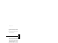
Setup for Most Tests
Most tests are performed at the front terminals as shown in the following figure.
Measure the dc voltage directly at the (+) and (-) terminals on the front panel.
3
Figure 3-1. Performance Verification Test Setup
Electronic Load
Many of the test procedures require the use of a variable load resistor capable of
dissipating the required power. Using a variable load resistor requires that switches
should be used to connect, disconnect, and short the load resistor. An electronic load,
if available, can be used in place of a variable load resistor and switches. The electronic
load is considerably easier to use than load resistors. It eliminates the need for
connecting resistors or rheostats in parallel to handle power, it is much more stable
than carbon-pile load, and it makes easy work of switching between load conditions
as is required for the load regulation and load response tests. Substitution of the
electronic load requires minor changes to the test procedures in this chapter.
49
Chapter 3 Calibration Procedures
Measurement Techniques
General Measurement Techniques
To achieve best results when measuring load regulation, peak to peak voltage, and
transient response time of the power supply, measuring devices must be connected
through the hole in the neck of the binding post at (A) while the load resistor is plugged
into the front of the output terminals at (B). A measurement made across the load
includes the impedance of the leads to the load. The impedance of the load leads can
easily be several orders of the magnitude greater than the power supply impedance
and thus invalidate the measurement. To avoid mutual coupling effects, each
measuring device must be connected directly to the output terminals by separate pairs
of leads.
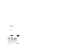
Figure 3-2. Front Panel Terminal Connections (Side View)
Current-Monitoring Resistor
To eliminate output current measurement error caused by the voltage drops in the
leads and connections, connect the current monitoring resistor between the (-) output
terminal and the load as a four-terminal device. Connect the current-monitoring leads
inside the load-lead connections directly at the monitoring points on the resistor
element (see RM in Figure 3-1).
Programming
Most performance tests can be performed from the front panel. However, an GPIB or
RS-232 controller is required to perform the voltage and current programming
accuracy and readback accuracy tests.
The test procedures are written assuming that you know how to program the power
supply either from the front panel or from an GPIB or RS-232 controller. Complete
instructions on front panel and remote programming are given in the Agilent E3633A
and E3634A User’s Guide.
50
Chapter 3 Calibration Procedures
Constant Voltage (CV) Verifications
Constant Voltage (CV) Verifications
Constant Voltage Test Setup
If more than one meter or if a meter and an oscilloscope are used, connect each to the
(+) and (-) terminals by a separate pair of leads to avoid mutual coupling effects. Use
coaxial cable or shielded 2-wire cable to avoid noise pick-up on the test leads.
Voltage Programming and Readback Accuracy
This test verifies that the voltage programming and GPIB or RS-232 readback
functions are within specifications. Note that the readback values over the remote
interface should be identical to those displayed on the front panel.
You should program the power supply over the remote interface for this test to avoid
round off errors.
1 Turn off the power supply and connect a digital voltmeter between the (+) and (-)
terminals of the output to be tested as shown in Figure 3-1.
2 Turn on the power supply. Select the 20V/10A* or 50V/4A** range and enable the
output by sending the commands:
VOLT:RANG P20V (E3633A)
VOLT:RANG P50V (E3634A)
OUTP ON
3 Program the output voltage to zero volt and current to full rated value
(10.0 A)* or (4.0 A)** by sending the commands:
VOLT 0
CURR 10 (E3633A)
CURR 4
(E3634A)
4 Record the output voltage reading on the digital voltmeter (DVM). The reading should
be within the limit of (0 V ± 10 mV). Also, note that the CV, Adrs, Limit, and Rmt
annunciators are on.
5 Readback the output voltage over the remote interface by sending the command:
MEAS:VOLT?
6 Record the value displayed on the controller. This value should be within the limit of
(DVM ±5 mV).
*For Agilent E3633A Model
**For Agilent E3634A Model
51
3
Chapter 3 Calibration Procedures
Constant Voltage (CV) Verifications
7 Program the output voltage to full rated value (20.0 V)* or (50.0 V)** by sending the
command:
VOLT 20.0 (E3633A)
VOLT 50.0 (E3634A)
8 Record the output voltage reading on the digital voltmeter (DVM). The reading should
be within the limit of (20 V ± 20 mV)* or (50 V ± 35mV)**.
9 Readback the output voltage over the remote interface by sending the command:
MEAS:VOLT?
10 Record the value displayed on the controller. This value should be within the limit of
(DVM ± 15 mV)* or (DVM ± 30 mV)**.
CV Load Effect (Load Regulation)
This test measures the immediate change in the output voltage resulting from a change
in the output current from full to no load.
1 Turn off the power supply and connect a digital voltmeter between the (+) and (-)
terminals of the output as shown in Figure 3-1.
2 Turn on the power supply. Select the 20V/10A* or 50V/4A** range, enable the output,
and set the display to the limit mode. When the display is in the limit mode, program
the output current to the maximum programmable value and the voltage to the full
rated value (20.0 V)* or (50.0 V)**.
3 Operate the electronic load in constant current mode and set its current to
(10.0 A)* or (4.0 A)**. Check that the front panel CV annunciator remains lit. If not
lit, adjust the load so that the output current drops slightly until the CV annunciator
lights. Record the output voltage reading on the digital voltmeter.
4 Operate the electronic load in open mode (input off). Record the output voltage
reading on the digital voltmeter immediately. The difference between the digital
voltmeter readings in steps (3) and (4) is the CV load regulation. The difference of
the readings during the immediate change should be within the limit of (4 mV)* or
(7 mV)**.
*For Agilent E3633A Model
52
**For Agilent E3634A Model
Chapter 3 Calibration Procedures
Constant Voltage (CV) Verifications
CV Source effect (Line Regulation)
This test measures the immediate change in output voltage that results from a change
in ac line voltage from the minimum value (10% below the nominal input voltage) to
maximum value (10% above the nominal input voltage).
1 Turn off the power supply and connect a digital voltmeter between the (+) and (-)
terminals of the output to be tested as shown in Figure 3-1.
2 Connect the ac power line through a variable voltage transformer.
3 Turn on the power supply. Select the 20V/10A* or 50V/4A** range, enable the output,
and set the display to the limit mode. When the display is in the limit mode, program
the current to the maximum programmable value and the voltage to full rated value
(20.0 V)* or (50.0 V)**.
4 Operate the electronic load in constant current mode and set its current to
(10.0 A)* or (4.0 A)**. Check that the CV annunciator remains lit. If not lit, adjust
the load so that the output current drops slightly until the CV annunciator lights.
5 Adjust the transformer to low line voltage limit (104 Vac for nominal 115 Vac, 90
Vac for nominal 100 Vac, or 207 Vac for nominal 230 Vac). Record the output reading
on the digital voltmeter.
6 Adjust the transformer to high line voltage (127 Vac for nominal 115 Vac, 110 Vac
for nominal 100 Vac, or 253 Vac for nominal 230 Vac). Record the voltage reading
on the digital voltmeter immediately. The difference between the digital voltmeter
readings in steps (5) and (6) is the CV line regulation. The difference of the readings
during the immediate change should be within the limit of (4 mV)* or (7 mV)**.
*For Agilent E3633A Model
**For Agilent E3634A Model
53
3
Chapter 3 Calibration Procedures
Constant Voltage (CV) Verifications
CV PARD (Ripple and Noise)
Periodic and random deviations (PARD) in the output (ripple and noise) combine to
produce a residual ac voltage superimposed on the dc output voltage. CV PARD is
specified as the rms or peak-to-peak output voltage in the frequency range from 20
Hz to 20 Mhz.
• VRMS measurement techniques:
When measuring Vrms ripple and noise, the monitoring device should be plugged into
the front of the terminals at (B) in Figure 3-2. Use the coaxial cable and BNC female
to banana plug adapter to connect the monitor device to the power supply. To reduce
the measurement error caused by common mode noise, it is recommended that you
use a common mode choke between the cable and the BNC adapter. The common
mode choke is constructed by inserting coaxial cable into Ferrite Toroidal core. The
load resistor should be connected to the terminal at (A) in Figure 3-2. Twisted leads
between the load resistor and the power supply helps reduce noise pickup for these
measurements.
1 Turn off the power supply and connect the output to be tested as shown in Figure 31 to an oscilloscope (ac coupled) between (+) and (-) terminals. Set the oscilloscope
to AC mode and bandwidth limit to 20 MHz. Connect a resistive load (2.0 Ω)* or
(12.5 Ω)** to the terminal at (A) in Figure 3-2.
2 Turn on the power supply. Select the 20V/10A* or 50V/4A** range, enable the output,
and set the display to the limit mode. When the display is in the limit mode, program
the current to the full rated value (10.0 A)* or (4.0 A)** and the voltage to the full
rated value (20.0 V)* or (50.0 V)**.
3 Check that the front panel CV annunciator remains lit. If not lit, adjust the load down
slightly.
4 Note that the waveform on the oscilloscope does not exceed the peak-to-peak limit
of 3 mV.
5 Disconnect the oscilloscope and connect the ac rms voltmeter in its place according
to the VRMS measurement techniques above. The rms voltage reading does not
exceed the rms limit of 0.35 mV* or 0.5 mV**.
*For Agilent E3633A Model
54
**For Agilent E3634A Model
Chapter 3 Calibration Procedures
Constant Voltage (CV) Verifications
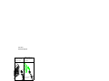
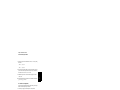
Load Transient Response Time
This test measures the time for the output voltage to recover to within 15 mV of
nominal output voltage following a load change from full load to half load, or half
load to full load.
1 Turn off the power supply and connect the output to be tested as shown in Figure 31 with an oscilloscope. Operate the electronic load in constant current mode.
2 Turn on the power supply. Select 20V/10A* or 50V/4A** range, enable the output,
and set the display to the limit mode. When the display is in the limit mode, program
the current to the full rated value (10.0 A)* or (4.0 A)** and the voltage to the full
rated value (20.0 V)* or (50.0 V)**.
3 Set the electronic load to transient operation mode between one half of the output’s
full rated value and the output’s full rated value at a 1 kHz rate with 50% duty cycle.
4 Set the oscilloscope for ac coupling, internal sync, and lock on either the positive or
negative load transient.
5 Adjust the oscilloscope to display transients as shown in Figure 3-3. Note that the
pulse width (t2 - t1) of the transients at 15 mV from the base line is no more than 50
μsec for the output.
Figure 3-3. Transient Response Time
*For Agilent E3633A Model
**For Agilent E3634A Model
55
3
Chapter 3 Calibration Procedures
Constant Current (CC) Verifications
Constant Current (CC) Verifications
Constant Current Test Setup
Follow the general setup instructions in the ‘‘Measurement Techniques’’ section,
starting on page 50 and the specific instructions will be given in the following
paragraphs.
Current Programming and Readback Accuracy
This test verifies that the current programming and GPIB or RS-232 readback
functions are within specifications. Note that the readback values over the remote
interface should be identical to those displayed on the front panel. The accuracy of
the current monitoring resistor must be 0.01% or better.
You should program the power supply over the remote interface for this test to avoid
round off errors.
1 Turn off the power supply and connect a 0.01 Ω current monitoring resistor (RM)
across the output to be tested and a digital voltmeter across the current monitoring
resistor (RM).
2 Turn on the power supply. Select the 8V/20A* or 25V/7A** range and enable the
output by sending the commands:
VOLT:RANG P8V
(E3633A)
VOLT:RANG P25V (E3634A)
OUTP ON
3 Program the output voltage to full rated voltage (8.0 V)* or (25.0 V)** and output
current to zero amps by sending the commands:
VOLT 8
(E3633A)
VOLT 25 (E3634A)
CURR 0
4 Divide the voltage drop (DVM reading) across the current monitoring resistor (RM)
by its resistance to convert to amps and record this value (IO). This value should be
within the limit of (0 A ± 10 mA). Also, note that the CC, Adrs, Limit, and Rmt
annunciators are on.
5 Readback the output current over the remote interface by sending the command:
MEAS:CURR?
6 Record the value displayed on the controller. This value should be within the limit of
(IO ± 5 mA).
*For Agilent E3633A Model
56
**For Agilent E3634A Model
Chapter 3 Calibration Procedures
Constant Current (CC) Verifications
7 Program the output current to the full rated value (20.0 A)* or (7.0 A)** by sending
the command:
CURR 20.0 (E3633A)
CURR 7.0
(E3634A)
8 Divide the voltage drop (DVM reading) across the current monitoring resistor (RM)
by its resistance to convert to amps and record this value (IO). This value should be
within the limit of (20 A ± 50 mA)* or (7A ± 24 mA)**.
9 Readback the output current over the remote interface by sending the command:
MEAS:CURR?
10 Record the value displayed on the controller. This value should be within the limit of
(IO ± 35 mA)* or (IO ± 15.5 mA)**.
CC Load Effect (Load Regulation)
This test measures the immediate change in output current resulting from a change in
the load from full rated output voltage to short circuit.
1 Turn off the power supply and connect the output to be tested as shown in
Figure 3-1 with the digital voltmeter connected across the 0.01 Ω current monitoring
resistor (RM).
2 Turn on the power supply. Select the 8V/20A* or 25V/7A** range, enable the output,
and set the display to the limit mode. When the display is in the limit mode, program
the output voltage to the maximum programmable value and the output current to the
full rated value (20.0 A)* or (7.0 A)**.
3 Set the voltage of the electronic load to (6.0 V)* or (23.0 V)** to operate it in constant
voltage mode since a voltage drop occurs on the load wires when
(20.0 A)* or (7.0 A)** flows on the load wires. Check that the CC annunciator is on.
If it is not, adjust the load so that the output voltage drops slightly. Record the current
reading by dividing the voltage reading on the digital voltmeter by the resistance of
the current monitoring resistor.
4 Operate the electronic load in short (input short) mode. Record the current reading
immediately by dividing the voltage reading on the digital voltmeter by the resistance
of the current monitoring resistor. The difference between the current readings in step
(3) and (4) is the load regulation current. The difference of the readings during the
immediate change should be within the limit of (2.25 mA)* or (0.95 mA)**.
*For Agilent E3633A Model
**For Agilent E3634A Model
57
3
Chapter 3 Calibration Procedures
Constant Current (CC) Verifications
CC Source Effect (Line Regulation)
This test measures the immediate change in output current that results from a change
in ac line voltage from the minimum value (10% below the nominal input voltage) to
the maximum value (10% above nominal voltage).
1 Turn off the power supply and connect the output to be tested as shown in Figure 31 with the digital voltmeter connected across the current monitoring resistor (RM).
2 Connect the ac power line through a variable voltage transformer.
3 Turn on the power supply. Select the 8V/20A* or 25V/7A** range, enable the output,
and set the display to the limit mode. When the display is in the limit mode, program
the voltage to the full rated value (8.0 V)* or (25.0 V)** and the current to the full
rated value (20.0 A)* or (7.0 A)**.
4 Operate the electronic load in constant voltage mode and set its voltage to
(8.0 V)* or (25.0 V)**. Check that the CC annunciator remains lit. If not lit, adjust
the load so that the output voltage drops slightly until the CC annunciator lights.
5 Adjust the transformer to low line voltage limit (104 Vac for nominal 115 Vac, 90
Vac for nominal 100 Vac, or 207 Vac for nominal 230 Vac). Record the output current
reading by dividing the voltage reading on the digital voltmeter by the resistance of
the current monitoring resistor.
6 Adjust the transformer to 10% above the nominal line voltage (127 Vac for a 115 Vac
nominal input, 110 Vac for a 100 Vac nominal input or 253 Vac for a 230 Vac nominal
input). Record the current reading again immediately by dividing the voltage reading
on the digital voltmeter by the resistance of the current monitoring resistor. The
difference between the current readings in step (5) and (6) is the load regulation
current. The difference of the readings during the immediate change should be within
the limit of (2.25 mA)* or (0.95 mA)**.
CC PARD (Ripple and Noise)
Periodic and random deviations (PARD) in the output (ripple and noise) combine to
produce a residual ac current, as well as an ac voltage superimposed on the dc output.
CC PARD is specified as the rms output current in a frequency range 20 Hz to 20
MHz with the power supply in constant current operation.
1 Turn off the power supply and connect the output to be tested as shown in Figure 31 with a load resistor (0.4 Ω)* or (3.5 Ω)** across output terminals. Connect a rms
voltmeter across the load resistor. Use only a resistive load for this test.
2 Turn on the power supply. Select the 8V/20A* or 25V/7A** range, enable the output,
and set the display to the limit mode. When the display is in the limit mode, program
the current to full rated value (20.0 A)* or (7.0 A)** and the voltage to the full rated
value (8.0 V)* or (25.0 V)**.
*For Agilent E3633A Model
58
**For Agilent E3634A Model
Chapter 3 Calibration Procedures
Common Mode Current Noise
3 The output current should be at the full rated rating with the CC annunciator on. If
not lit, adjust the load so that the output voltage drops slightly until the CC annunciator
lights.
4 Divide the reading on the rms voltmeter by the load resistance to obtain rms current.
The readings should be within the limit of 2 mA.
Common Mode Current Noise
3
The common mode current is that ac current component which exists between the
output or output lines and chassis ground. Common mode noise can be a problem for
very sensitive circuitry that is referenced to earth ground. When a circuit is referenced
to earth ground, a low level line-related ac current will flow from the output terminals
to earth ground. Any impedance to earth ground will create a voltage drop equal to
the output current flow multiplied by the impedance.
1 Turn off the power supply and connect a 100 kΩ resistor (RS) and a 2200 pF capacitor
in parallel between the (-) terminal and chassis ground.
2 Connect a digital voltmeter across RS.
3 Turn on the power supply. Select the 8V/20A* or 25V/7A** range, enable the output,
and set the display to the limit mode. When the display is in the limit mode, program
the output to the full rated value (8.0 V and 20.0 A)* or (25.0 V and 7.0 A)**.
4 Record the voltage across RS and convert it to current by dividing by the resistance
(DVM reading/100 kΩ). Note that the current is less than 1.5 μA.
*For Agilent E3633A Model
**For Agilent E3634A Model
59
Chapter 3 Calibration Procedures
Performance Test Record for Agilent E3633A and E3634A
Performance Test Record for Agilent E3633A and E3634A
CV Performance Test Record
Test Description
Models
Actual Result
Specifications
Upper Limit
Lower Limit
CV Programming Accuracy @ 0
volts (DVM reading)
both
+0.0100 V
-0.0100 V
CV Readback Accuracy @ 0 volts
both
DVM + 0.0050 V
DVM - 0.0050 V
CV Programming Accuracy
@ Full Scale (DVM reading)
(E3633A)
+20.0200 V
19.9800 V
(E3634A)
+50.0350 V
49.9650 V
CV Readback Accuracy @ Full Scale (E3633A)
DVM + 0.0150 V
DVM - 0.0150 V
(E3634A)
DVM + 0.0300 V
DVM - 0.0300 V
CV Load Effect (Load Regulation)
Maximum change: < (4 mV)* or (7 mV)**
CV Source Effect (Line Regulation)
Maximum change: < (4 mV)* or (7 mV)**
CV PARD (Normal mode)
< 3 mV p-p, (350 μV)* or (500 μV)** rms
Load Transient Response Time
< 50 μsec
both
CC Performance Test Record
Test Description
Models
Actual Result
Specifications
Upper Limit
Lower Limit
CC Programming Accuracy
@ 0 amps (IO)
both
+0.0100 A
-0.0100 A
CC Readback Accuracy @ 0 amps
both
IO + 0.0050 A
IO - 0.0050 A
CC Programming Accuracy
@ Full Scale (IO)
(E3633A)
20.0500 A
19.9500 A
(E3634A)
7.0230 A
6.9770 A
IO + 0.0350 A
IO - 0.0350 A
IO + 0.0155 A
IO - 0.0155 A
CC Readback Accuracy @ Full Scale (E3633A)
(E3634A)
CC Load Effect (Load Regulation)
Maximum change: < (2.25 mA)* or (0.95 mA)**
CC Source Effect (Line Regulation)
Maximum change: < (2.25 mA)* or (0.95 mA)**
CC PARD (Normal mode)
both
< 2 mA rms
CC PARD (Common mode)
both
< 1.5 μA rms
*For Agilent E3633A Model
60
**For Agilent E3634A Model
Chapter 3 Calibration Procedures
Calibration Security Code
Calibration Security Code
This feature allows you to enter a security code (electronic key) to prevent accidental
or unauthorized calibrations of the power supply. When you first receive your power
supply, it is secured. Before you can calibrate the power supply, you must unsecure
it by entering the correct security code. A procedure to unsecure the power supply is
given on the following page.
• The security code is set to ‘‘HP003633’’* or ‘‘HP003634’’** when the power
supply is shipped from the factory. The security code is stored in non-volatile
memory, and does not change when power has been off or after a remote interface
reset.
• To secure the power supply from the remote interface, the security code may
contain up to 12 alphanumeric characters as shown below. The first character must
be a letter, but the remaining characters can be letters or numbers. You do not have
to use all 12 characters but the first character must always be a letter.
A_ _ _ _ _ _ _ _ _ _ _
(12 characters)
• To secure the power supply from the remote interface so that it can be unsecured
from the front panel, use the eight-character format shown below. The first two
characters must be ‘‘H P’’ and the remaining characters must be numbers. Only
the last six characters are recognized from the front panel, but all eight characters
are required. To unsecure the power supply from the front panel, omit the ‘‘HP’’
and enter the remaining numbers as shown on the following pages.
HP _ _ _ _ _ _
(8 characters)
• If you forget your security code, you can disable the security feature by adding a
jumper inside the power supply, and then entering a new code.
See the procedure on page 63.
*For Agilent E3633A Model
**For Agilent E3634A Model
61
3
Chapter 3 Calibration Procedures
Calibration Security Code
To Unsecure the Power Supply for Calibration
The power supply can use a calibration security code to prevent unauthorized or
accidental calibration. This procedure shows you how to unsecure the power supply
for calibration from the front panel.
Error
Calibrate
1 Turn on the front-panel calibration mode.
SECURED
Error
Turn on the calibration mode by holding down Calibrate (Calibrate) key as you turn on
the power supply and hold down the key until you hear a long beep.
If the power supply is secured, you will see the above message from the front panel
for approximately one second. The ‘‘CAL MODE’’ message is then displayed on the
front panel.
I/O
Config
Secure
2 Move to the security code by pressing
I/O
Config
Secure
(Secure) key.
000000 CODE
3 Enter the security code using the knob and resolution selection keys.
003633 CODE (E3633A)
003634 CODE (E3634A)
The security code is set to ‘‘HP003633’’* or ‘‘HP003634’’** when the power supply
is shipped from the factory. The security code is stored in non-volatile memory and
does not change when the power has been off or after a remote interface reset.
• To enter the security code from the front panel, enter only the last six digits.
• To enter the security code from the remote interface, you may enter up to 12
characters.
Use the resolution selection keys to move left or right between digits. Use the knob
to change the digits. Notice that the security code may be different if the security code
has been changed from the default setting.
*For Agilent E3633A Model
62
**For Agilent E3634A Model
Chapter 3 Calibration Procedures
Calibration Security Code
I/O
Config
Secure
4 Unsecure the power supply.
UNSECURED
I/O
The power supply is unsecured when you press Config
(Secure) key. You will see the
Secure
above message from the front panel for one second. The ‘‘CAL MODE’’ message is
displayed on the front panel after above message.
Power
5 Turn off the calibration mode.
Turn off the power supply to exit the calibration mode.
3
To re-secure the power supply (following calibration), perform this procedure
again.
To Unsecure the Power Supply Without the Security Code
To unsecure the power supply without the correct security code (when you forget the
security code), follow the steps below. See ‘‘Electrostatic Discharge (ESD)
Precautions’’ in chapter 5 before beginning this procedure.
1 Disconnect the power cord and all load connections from the power supply.
2 Remove the instrument cover.
Error
3 Connect the power cord and turn on the calibration mode by holding down Calibrate
(Calibrate) key as you turn on the power supply and hold down the key until you hear
a long beep. Be careful not to touch the power line connections.
4 Apply a short between the two exposed metal pads on JP5[1] (located near U13). The
JP5 is outlined with a circle on the component locator drawing on page 111.
5 While maintaining the short, move to the security code and enter any unsecure code
in the calibration mode. The power supply is now unsecured.
6 Remove the short at JP5[2]. (An error occurs if not removed.)
7 Turn off and reassemble the power supply.
Now you can enter a new security code. Be sure you take note of the new security code.
[1]For serial MY53xx6xxx, apply a short between the two exposed metal pads on
JP102 (located near U103). The JP102 is outlined with a circle on the component
locator drawing on page 113.
[2]For serial MY53xx6xxx, remove the short at JP102.
63
Chapter 3 Calibration Procedures
Calibration Count
Calibration Count
The calibration count feature provides an independent ‘‘serialization’’ of your
calibrations. You can determine the number of times that your power supply has been
calibrated. By monitoring the calibration count, you can determine whether an
unauthorized calibration has been performed. Since the value increments by one for
each calibration parameter (see Table 3-2 on the next page), a complete calibration
increases the value by 5 counts.
• The calibration count is stored in non-volatile memory and does not change when
power has been off or after a remote interface reset. Your power supply was
calibrated before it left the factory. When you receive the power supply, read the
calibration count to determine its value.
• The calibration count increments up to a maximum of 32,767 after which it wraps
around to 0. No way is provided to program or reset the calibration count.
Calibration Message
You can use the calibration message feature to record calibration information about
your power supply. For example, you can store such information as the last calibration
date, the next calibration due date, the power supply’s serial number, or even the name
and phone number of the person to contact for a new calibration.
You can record and read information in the calibration message from the remote
interface only.
• The calibration message may contain up to 40 characters.
• The calibration message is stored in non-volatile memory and does not change
when power has been off or after a remote interface reset.
• Remote Interface Operation
CAL:SEC:STAT {OFF|ON},<code> Secure or unsecure the power supply
CAL:SEC:CODE <new code>
Change the security code
CAL:STR <quoted string>
Store the calibration message
CAL:STR?
Query the calibration information
See “Calibration Overview”, starting on page 68 in chapter 3 of the User’s Guide for
more details.
64
Chapter 3 Calibration Procedures
General Calibration/Adjustment Procedure
General Calibration/Adjustment Procedure
The calibration procedures from the front panel are described in this section. For
voltage calibration, disconnect all loads from the power supply and connect a DVM
across the output terminals. For current calibration, disconnect all loads from the
power supply, connect an appropriate current monitoring resistor 0.01 Ω across the
output terminals, and connect a DVM across the terminals of the monitoring resistor.
Note that the power supply should be calibrated after 1-hour warm-up with no load
connected.
The following table shows calibration parameters and points which should be used to
calibrate the output voltage and current.
Table 3-2. Parameters for Calibration
Calibration
Parameter
Voltage/
Current
Calibration Point
mnemonic
V LO
CAL SETUP 1
Voltage
CAL SETUP 2
OVP
V MI
V HI
None
I LO
CAL SETUP 3
Current
CAL SETUP 4
OCP
I MI
I HI
None
Note
You can terminate any CAL SETUP without changing its calibration constants by
turning off power.
Note
Perform the voltage calibration prior to the OVP calibration and the current
calibration prior to the OCP calibration.
65
3
Chapter 3 Calibration Procedures
General Calibration/Adjustment Procedure
Front Panel Voltage and Current Calibration
1 Unsecure the power supply.
To calibrate the voltage and current, you must unsecure the power supply according
to the procedure given on page 62.
2 Disconnect all loads from the power supply and connect a DVM across output
terminals.
Error
Calibrate
3 Turn on the calibration mode.
CAL MODE
Error
Turn on the calibration mode by holding down Calibrate (Calibrate) key as you turn on
the power supply and hold down the key until you hear a long beep. Make sure that
the power supply is in ‘‘CV’’ mode. If the power supply is not in ‘‘CV’’ mode, an
error occurs.
Voltage and OVP Calibration
Error
Calibrate
4 Move down a level to the voltage calibration mode.
CAL SETUP 1
The display shows the above message to indicate that the power supply is ready for
voltage calibration.
Error
Calibrate
5 Calibrate DAC and select the low voltage calibration point.
30 LEFT
The ‘‘START BITCAL’’ message is displayed for about 3 seconds to indicate that the
power supply is ready for DAC calibration. Then it counts down numbers from 30 to 0.
V LO 0.5000 V
Then, the display shows the low voltage calibration point.
66
Chapter 3 Calibration Procedures
General Calibration/Adjustment Procedure
6 Read the DVM and change the low voltage value on the display to match the
measured voltage.
For example, if the DVM reading is 0.4500 V, adjust the voltage to 0.4500 V using
the knob and resolution selection keys.
V LO 0.4500 V
Error
Calibrate
Error
7 Pressing Calibrate (Calibrate) key saves the change and selects the middle voltage
calibration point. (‘‘V MI 25.000 V’’ - E3634A model)
V MI 10.000 V (E3633A)
If the entered number is within an acceptable range, an ‘‘ENTERED’’ message
appears for one second. If the entered number is not correct, an ‘‘MIN VALUE’’ or
‘‘MAX VALUE’’ message appears for one second and the display shows the low
voltage calibration point again. The display now shows the middle voltage calibration
point.
8 Read the DVM and change the middle voltage value on the display to match the
measured voltage.
For example, if the DVM reads 10.001 V, adjust the voltage to 10.001 V using the
knob and arrow keys.
V MI 10.001 V
Error
Calibrate
Error
9 Pressing Calibrate (Calibrate) key saves the changes and selects the high voltage
calibration point. (‘‘V HI 49.500 V’’ - E3634A model)
V HI 19.500 V (E3633A)
If the entered number is within an acceptable range, an ‘‘ENTERED’’ message
appears for one second. If the entered number is not correct, an ‘‘MIN VALUE’’ or
‘‘MAX VALUE’’ message appears for one second and the display shows the middle
voltage calibration point again. The display now shows the high voltage calibration
point.
67
3
Chapter 3 Calibration Procedures
General Calibration/Adjustment Procedure
10 Read the DVM and change the high voltage value on the display to match the
measured voltage.
For example, if the DVM reads 19.495 V, adjust the voltage to 19.495 V using the
knob and arrow keys.
V HI 19.495 V
Error
Calibrate
Error
11 Pressing Calibrate (Calibrate) key saves the new voltage calibration constants, and
goes to the OVP calibration mode.
CAL SETUP 2
A ‘‘CALIBRATING’’ message appears for one second to indicate that the voltage
calibration is progressing and new voltage calibration constants of ‘‘SETUP 1’’ are
stored. Then, the display shows above message to indicate that the power supply is
ready for the OVP calibration.
If the calibration fails, a ‘‘DAC CAL FAIL’’ or ‘‘ADC CAL FAIL’’ message appears
for one second and the display shows the ‘‘CAL SETUP 1’’ for voltage calibration
again.
Current and OCP Calibration
Error
Calibrate
Error
12 Pressing Calibrate (Calibrate) key saves the new calibration constants for OVP
circuit and goes to the current calibration mode.
CAL SETUP 3
A ‘‘CALIBRATING’’ message appears for about several seconds to indicate that the
OVP calibration is progressing and new calibration constants of ‘‘SETUP 2’’ are
stored. Then, the display shows the above message to indicate that the power supply
is ready for the current calibration.
Connect an appropriate shunt 0.01 Ω across the output terminals, and connect a
digital voltmeter across the shunt resistor for the current calibration.
68
Chapter 3 Calibration Procedures
General Calibration/Adjustment Procedure
If the calibration fails, a ‘‘OVP CAL FAIL’’ message appears for one second and the
display shows the ‘‘CAL SETUP 2’’ for OVP calibration again.
Error
Calibrate
13 Select the low current calibration point.
(‘‘I LO 0.2000 A’’ - E3634A model)
I LO 0.5000 A (E3633A)
The display shows the low current calibration point.
14 Read the DVM and change the low current value on the display to match the
computed current (DVM reading ÷ by shunt resistance).
For example, if the computed value is 0.4990 A, adjust the current to 0.4990 A using
the knob and arrow keys.
Notice that you should wait for the DVM reading to stabilize for accurate calibration.
I LO 0.4990 A
Error
Calibrate
15 Pressing the ‘‘Calibrate’’ key saves the change and selects the middle current
calibration point. (‘‘I MI 3.5000 A’’ - E3634A model)
I MI 10.000 A (E3633A)
If the entered number is within an acceptable range, an ‘‘ENTERED’’ message
appears for one second. If the entered number is not correct, an ‘‘MIN VALUE’’ or
‘‘MAX VALUE’’ message appears for one second and the display shows the low
current calibration point again. The display now shows the middle current calibration
point.
16 Read the DVM and change the middle current value on the display to match the
computed current (DVM reading ÷ by shunt resistance).
For example, if the computed value is 9.999 A, adjust the current to 9.999 A using
the knob and arrow keys.
Notice that you should wait for the DVM reading to stabilize for accurate calibration.
I MI 09.999 A
69
3
Chapter 3 Calibration Procedures
General Calibration/Adjustment Procedure
Error
Calibrate
17 Pressing the ‘‘Calibrate’’ key saves the change and selects the high current
calibration point. (‘‘I HI 6.9000 A’’ - E3634A model)
I HI 19.500 A (E3633A)
If the entered number is within an acceptable range, an ‘‘ENTERED’’ message
appears for one second. If the entered number is not correct, an ‘‘MIN VALUE’’ or
‘‘MAX VALUE’’ message appears for one second and the display shows the middle
current calibration point again. The display now shows the high current calibration
point
18 Read the DVM and change the high current value on the display to match the
computed current (DVM reading ¸ by shunt resistance).
For example, if the computed value is 19.499 A, adjust the current to 19.499 A using
the knob and arrow keys.
Notice that you should wait for the DVM reading to stabilize for accurate calibration.
I HI 19.499 A
Error
Calibrate
19 Pressing the ‘‘Calibrate’’ key saves the new calibration constants for the output
current and goes to the OCP calibration mode.
CAL SETUP 4
A ‘‘CALIBRATING’’ message appears for one second to indicate that the current
calibration is progressing and new calibration constants of ‘‘SETUP 3’’ are stored.
Then, the display shows the above message to indicate that the power supply is ready
for the OCP calibration.
If the calibration fails, an ‘‘DAC CAL FAIL’’ or ‘‘ADC CAL FAIL’’ message appears
for one second and the display shows the ‘‘CAL SETUP 3’’ for current calibration
again.
70
Chapter 3 Calibration Procedures
Aborting a Calibration in Progress
Error
Calibrate
20 Pressing the ‘‘Calibrate’’ key saves the new OCP calibration constants and
return to the calibration mode.
CAL MODE
A ‘‘CALIBRATING’’ message appears for several seconds to indicate that the OCP
calibration is progressing and new OCP calibration constants of ‘‘SETUP 4’’ are
stored. Then the display will return to the calibration mode.
If the calibration fails, a ‘‘OCP CAL FAIL’’ message appears for one second and the
display shows the ‘‘CAL SETUP 4’’ for OCP calibration again.
Power
Turn off the power supply to exit the calibration mode.
Aborting a Calibration in Progress
Sometimes it may be necessary to abort a calibration after the procedure has already
been initiated. You can abort a calibration at any time by turning the power supply
off from the front panel. When performing a calibration from the remote interface,
you can abort a calibration by issuing a remote interface device clear message or by
pressing the front-panel ‘‘Local’’ key.
71
3
Chapter 3 Calibration Procedures
Calibration Record for Agilent E3633A/E3634A
Calibration Record for Agilent E3633A/E3634A
Step
Measurement
Mode (DVM)
Calibration Description
Supply Being
Adjusted
1
Unsecure the power supply (see page 62).
2
Turn on ‘‘CAL MODE’’ (hold down ‘‘Calibrate’’ and ‘‘Power’’ keys as
you turn on the power supply until you hear a long beep).
3
Move down menu to ‘‘CAL SETUP 1’’ (press ‘‘Calibrate’’ key).
4
Calibrate DAC and select the low point for voltage calibration; ‘‘START
BITCAL’’ appears for about 3 seconds and the display counts down
numbers from 30 to 0. Then, ‘‘V LO 0.5000 V’’ appears on the display
(press ‘‘Calibrate’’ key and wait about 30 seconds; then change the
display to match the DVM reading).
V
DAC and low voltage
point calibration
5
‘‘V MI 10.000 V’’* or ‘‘V MI 25.000 V’’** appears on the display (press
‘‘Calibrate’’ key; then change the display to match the DVM reading).
V
Middle voltage point
calibration
6
‘‘V HI 19.500 V’’* or ‘‘V HI 49.500 V’’** appears on the display (press
‘‘Calibrate’’ key; then change the display to match the DVM reading).
V
High voltage point
calibration
7
‘‘CAL SETUP 2’’ now appears on the display (press ‘‘Calibrate’’ key).
V OVP calibration
8
‘‘CAL SETUP 3’’ now appears on the display (press ‘‘Calibrate’’ key;
then connect 0.01 Ω resistor across the output terminals).
9
‘‘I LO 0.5000 A’’* or ‘‘I LO 0.2000 A’’** appears on the display (press
‘‘Calibrate’’ key; then change the display to match the computed current
through the resistor).
A
Low current point
calibration
10
‘‘I MI 10.000 A’’* or ‘‘I MI 3.5000 A’’** appears on the display (press
‘‘Calibrate’’ key; then change the display to match the computed current
through the resistor).
A
Middle current point
calibration
11
‘‘I HI 19.500 A’’* or ‘‘I HI 6.9000 A’’** appears on the display (press
‘‘Calibrate’’ key; then change the display to match the computed current
through the resistor).
A
High current point
calibration
12
‘‘CAL SETUP 4’’ now appears on the display (press ‘‘Calibrate’’ key).
A OCP calibration
13
Press ‘‘Calibrate’’ key, then press ‘‘Power’’ switch.
*For Agilent E3633A Model
72
**For Agilent E3634A Model
Voltage Calibration
Current calibration
Exit CAL MODE
Chapter 3 Calibration Procedures
Error Messages
Error Messages
The following tables are abbreviated lists of error messages for the E3633A and
E3634A. The errors listed are the most likely errors to be encountered during
calibration and adjustment. A more complete list of error messages and descriptions
is contained in chapter 5 of the E3633A and E3634A User’s Guide.
System Error Messages
Error
-330
-350
501
502
503[1]
511
512
513
514
521
522
550
Error Messages
Self-test failed
Queue overflow
Isolator UART framing error
Isolator UART overrun error
SPI data error
RS-232 framing error
RS-232 overrun error
RS-232 parity error
Command allowed only with RS-232
Input buffer overflow
Output buffer overflow
Command not allowed in local
3
[1]This error message is only applicable for serial MY53xx6xxx.
73
Chapter 3 Calibration Procedures
Error Messages
Self-Test Error Messages
Error
601
602
603
604
605
606
607
608
609[1]
624
625
626
630
631
632
Error Messages
Front panel does not respond
RAM read/write failed
A/D sync stuck
A/D slope convergence failed
Cannot calibrate rundown gain
Rundown gain out of range
Rundown too noisy
Serial configuration readback failed
System ADC test failed
Unable to sense line frequency
I/O processor does not respond
I/O processor failed self-test
Fan test failed
System DAC test failed
Hardware test failed
[1]This error message is only applicable for serial MY53xx6xxx.
74
Chapter 3 Calibration Procedures
Error Messages
Calibration Error Messages
Error
701
702
703
704
705
708
712
713
714
715
716
717
718
740
741
742
743
744
745
746
747
748
749
750
Error Messages
Cal security disabled by jumper
Cal secured
Invalid secure code
Secure code too long
Cal aborted
Cal output disabled
Bad DAC cal data
Bad readback cal data
Bad OVP cal data
Bad OCP cal data
Bad DAC DNL error correction data
Cal OVP or OCP status enabled
Gain out of range for gain error correction
Cal checksum failed, secure state
Cal checksum failed, string data
Cal checksum failed, store/recall data in location 0
Cal checksum failed, store/recall data in location 1
Cal checksum failed, store/recall data in location 2
Cal checksum failed, store/recall data in location 3
Cal checksum failed, DAC cal constants
Cal checksum failed, readback cal constants
Cal checksum failed, GPIB address
Cal checksum failed, internal data
Cal checksum failed, DAC DNL error correction data
3
Continued on next page
75
Chapter 3 Calibration Procedures
An Example program of Excel 97 for Calibration
An Example program of Excel 97 for Calibration
This section contains an Excel Macros (Visual Basic® for Applications) program for
calibration over the GPIB interface. This program makes software adjustments to the
E3633A power supply using a current shunt and a digital multimeter which is
connected to the controller. In this program a 0.001 ohm current shunt is used. Be sure
to change the value of the variable ‘‘shunt’’ to the value of the current shunt used and
the GPIB address for the power supply and the digital voltmeter.
'**************************************************************************************
® for Applications)
'This program was written on a PC with Excel Macros (Visual Basic
'for Windows 95 or Windows NT 4.0. It will make software adjustments to the E3633A
'Power Supply on the GPIB bus using a Agilent 34401A Digital Multimeter and a current
'shunt. In the program a 0.001 ohm current shunt is used to measure current. Be sure to
'change the value of the variable ‘shunt’ to the value of the current shunt used.
'**************************************************************************************
Global id_power As Long
Global id_DMM As Long
Global power As Long
Global DMM As Long
Global Const VI_SUCCESS = &H0&
Global Const VoltageMin = 0
Global Const VoltageMid = 1
Global Const VoltageMax = 2
Global Const CurrentMin = 3
Global Const CurrentMid = 4
Global Const CurrentMax = 5
Sub Calibration_Click()
Dim shunt As Single 'Current shunt value in Ohms
Dim UserAnswer
'User response
Range("B4:B6").ClearContents
If OpenPort = False Then
ClosePort
Exit Sub
End If
InitializeDevice
EnableOVPandOCP False
If CheckSecurity = False Then
ClosePort
Exit Sub
End If
76
Continued on next page
Chapter 3 Calibration Procedures
An Example program of Excel 97 for Calibration
If DacErrorCorrection = False Then
ClosePort
Exit Sub
End If
shunt = 0.001 'Change the current shunt value
UserAnswer = MsgBox("Voltage & OVP calibration. Connect the output to the DMM",
vbYesNo + vbQuestion, "E3633A Calibration")
If UserAnswer = vbNo Then
ClosePort
Exit Sub
End If
3
Range("B4").Select
ActiveCell.Value = "Begin Voltage Calibration"
StartCalibration VoltageMin, True, shunt 'Set output to minimum voltage cal
ActiveCell.Value = "End Minimum Voltage Calibration"
StartCalibration VoltageMid, True, shunt 'Set output to middle voltage cal
ActiveCell.Value = "End Middle Voltage Calibration"
StartCalibration VoltageMax, True, shunt 'Set output to maximum voltage cal
ActiveCell.Value = "End Maximum Voltage Calibration"
Message = SendSCPI(power, "Syst:Err?")
If InStr(Message, "0") Then
ActiveCell.Value = "Voltage Calibration Complete"
Else
ActiveCell.Value = Message
ClosePort
Exit Sub
End If
OVPandOCPCalibration True
UserAnswer = MsgBox("Connect the Current shunt to the DMM input to measure a current.
Connect the output to the shunt.", vbYesNo + vbQuestion, "E3633A Calibration")
If UserAnswer = vbNo Then
ClosePort
Exit Sub
End If
ActiveCell.Value
StartCalibration
ActiveCell.Value
StartCalibration
= "Begin Current Calibration"
CurrentMin, False, shunt
'Set output to minimum current cal
= "End Minimum Current Calibration"
CurrentMid, False, shunt
'Set output to middle current cal
Continued on next page
77
Chapter 3 Calibration Procedures
An Example program of Excel 97 for Calibration
ActiveCell.Value = "End Middle Current Calibration"
StartCalibration CurrentMax, False, shunt
'Set output to maximum current cal
ActiveCell.Value = "End Maximum Current Calibration"
OVPandOCPCalibration False
Message = SendSCPI(power, "Syst:Err?")
If InStr(Message, "0") Then
ActiveCell.Value = "Current Calibration Complete"
Else
ActiveCell.Value = Message
ClosePort
Exit Sub
End If
EnableOVPandOCP True
SaveDate
ActiveCell.Value = "Calibration Complete"
Message = SendSCPI(power, "*RST")
ClosePort
End Sub
Private
Dim
Dim
Dim
Function OpenPort() As Boolean 'Open communications on GPIB
Power_Address As String
DMM_Address As String
Error As Long
Power_Address = "5" 'Select power supply GPIB address between 0 to 30
DMM_Address = "22"
'Select DMM GPIB address between 0 to 30
Error = viOpenDefaultRM(id_power) 'Open the power supply VISA session
If OpenPort = CheckError(Error, "Open ID Error to Power Supply") Then
Exit Function
End If
Error = viOpenDefaultRM(id_DMM) 'Open the DMM VISA session
If OpenPort = CheckError(Error, "Open ID Error to Digital Multi Meter") Then
Exit Function
End If
Error = viOpen(id_power, "GPIB0::" & Power_Address & "::INSTR", 0, 1000, power)
If OpenPort = CheckError(Error, "Unable Open to Power Supply") Then
Exit Function
End If
Error = viOpen(id_DMM, "GPIB0::" & DMM_Address & "::INSTR", 0, 1000, DMM)
If OpenPort = CheckError(Error, "Unable Open to Digital Multi Meter") Then
Exit Function
End If
OpenPort = True
End Function
Continued on next page
78
Chapter 3 Calibration Procedures
An Example program of Excel 97 for Calibration
Private Function InitializeDevice()
SendSCPI power, "*Cls"
SendSCPI DMM, "*Rst"
'Set power-on condition for DMM
SendSCPI power, "*Rst" 'Set power-on condition for power supply
End Function
Private Function CheckError(Error As Long, Message As String) As Boolean
If Error < VI_SUCCESS Then
ActiveCell.Value = Message
CheckError = False
'Exit Calibration
Else
CheckError = True
End If
End Function
3
Private Function ClosePort()
Dim Error As Long
Error = viClose(power)
Error = viClose(id_power)
Error = viClose(DMM)
Error = viClose(id_DMM)
End Function
Private Function EnableOVPandOCP(bEnable As Boolean)
If bEnable Then
SendSCPI power, "Volt:Prot:Stat On"
SendSCPI power, "Curr:Prot:Stat On"
Else
SendSCPI power, "Volt:Prot:Stat Off"
SendSCPI power, "Curr:Prot:Stat Off"
End If
End Function
'This routine send a SCPI command string to the GPIB port.
'If the command contains a question mark, the response is read, and returned
Private Function SendSCPI(device As Long, command As String) As String
Dim commandString As String
Dim ReturnString As String
Dim crlfpos As Integer
Dim ReadBuffer As String * 512
Dim actual As Long
Dim Error As Long
commandString = command & Chr$(10)
Continued on next page
79
Chapter 3 Calibration Procedures
An Example program of Excel 97 for Calibration
Error = viWrite(device, ByVal commandString, Len(commandString), actual)
If InStr(commandString, "?") Then
Error = viRead(device, ByVal ReadBuffer, 512, actual)
ReturnString = ReadBuffer
crlfpos = InStr(ReturnString, Chr$(0))
If crlfpos Then
ReturnString = Left(ReturnString, crlfpos - 2)
End If
SendSCPI = ReturnString
End If
End Function
Private Function delay(delay_time As Single)
Dim Finish As Single
Finish = Timer + delay_time
Do
Loop Until Finish <= Timer
End Function
'This routine is used to create delays
Private Function CheckSecurity() As Boolean
Dim Message As String
Dim SecurityCode As String
Message = SendSCPI(power, "Cal:Str?")
Range("B5").Select
ActiveCell.Value = Message
Message = SendSCPI(power, "Cal:Count?")
Range("B6").Select
ActiveCell.Value = Message
Range("B4").Select
SecurityCode = "HP003633"
SendSCPI power, "Cal:Sec:Stat Off," & SecurityCode
Message = SendSCPI(power, "Cal:Sec:Stat?")
If InStr(Message, "1") Then
ActiveCell.Value = "Unable to Unsecure the Power Supply"
CheckSecurity = False
Else
Message = SendSCPI(power, "Syst:Err?")
If InStr(Message, "0") Then
CheckSecurity = True
Else
ActiveCell.Value = Message
CheckSecurity = False
End If
End If
End Function
80
Continued on next page
Chapter 3 Calibration Procedures
An Example program of Excel 97 for Calibration
Private Function DacErrorCorrection() As Boolean
Dim Message As String
SendSCPI power, "Output On"
'Turn on the power supply output
SendSCPI power, "Cal:Dac:Error"
For I = 1 To 27
delay 1
ActiveCell.Value = "Waitting for " & Str$(27 - I) & "secs"
Next I
SendSCPI power, "Output Off"
'Turn off the power supply output
Message = SendSCPI(power, "Syst:Err?")
If InStr(Message, "0") Then
ActiveCell.Value = "DAC DNL Error Correction completed for power supply"
DacErrorCorrection = True
Else
ActiveCell.Value = Message
DacErrorCorrection = False
End If
End Function
3
Private Function StartCalibration(mode As Integer, bVolt As Boolean, shunt As Single)
Dim DMMdata As Single
SendSCPI power, "Output
Select Case mode
Case VoltageMin
SendSCPI power,
Case VoltageMid
SendSCPI power,
Case VoltageMax
SendSCPI power,
Case CurrentMin
SendSCPI power,
Case CurrentMid
SendSCPI power,
Case CurrentMax
SendSCPI power,
End Select
On" 'Turn on the power supply output
"Cal:Volt:Level Min" 'Set output to minimum cal value
"Cal:Volt:Level Mid" 'Set output to middle cal value
"Cal:Volt:Level Max" 'Set output to maximum cal value
"Cal:Curr:Level Min" 'Set output to minimum cal value
"Cal:Curr:Level Mid" 'Set output to middle cal value
"Cal:Curr:Level Max" 'Set output to maximum cal value
delay 4
DMMdata = SendSCPI(DMM, "Meas:Volt:DC?")
'measure output
81
Chapter 3 Calibration Procedures
An Example program of Excel 97 for Calibration
If bVolt Then
'Send the measured voltage value to the power supply
SendSCPI power, "Cal:Volt:Data " & Str(DMMdata)
Else
'Send the measured current value to the power supply
SendSCPI power, "Cal:Curr:Data " & Str(DMMdata / shunt)
End If
SendSCPI power, "Output Off"
'Turn off the power supply output
End Function
Private Function OVPandOCPCalibration(bVolt As Boolean)
SendSCPI power, "Output On" 'Turn on the power supply output
If bVolt Then
ActiveCell.Value = " Begin OVP Calibration"
SendSCPI power, "Cal:Volt:Prot" 'Perform OVP circuit calibration
Else
ActiveCell.Value = " Begin OCP Calibration"
SendSCPI power, "Cal:Curr:Prot" 'Perform OCP circuit calibration
End If
delay 9
SendSCPI power, "Output Off"
'Turn off the power supply output
End Function
Private Function SaveDate()
Dim Message As String
'calibration string enclosed in quotes
Message = "Cal:Str " & Chr(34) & Date & Chr(34)
SendSCPI power, Message
Message = SendSCPI(power, "Cal:Str?")
Range("B5").Select
ActiveCell.Value = Message
Message = SendSCPI(power, "Cal:Count?")
Range("B6").Select
ActiveCell.Value = Message
Range("B4").Select
End Function
End of Program
82
Chapter 3 Calibration Procedures
An Example program of Excel 97 for Calibration
Declaration for Windows 95/NT 4.0
Declare Function viOpenDefaultRM Lib "visa32.dll" (instrumentHandle As Long) As Long
Declare Function viOpen Lib "visa32.dll" (ByVal instrumentHandle As Long, _
ByVal viDesc As String, ByVal mode As Long, ByVal timeout As Long, _
vi As Long) As Long
Declare Function viClose Lib "visa32.dll" (ByVal vi As Long) As Long
Declare Function viWrite Lib "visa32.dll" (ByVal vi As Long, ByVal Buffer As String,
ByVal count As Long, retCount As Long) As Long
3
Declare Function viRead Lib "visa32.dll" (ByVal vi As Long, ByVal Buffer As String, _
ByVal count As Long, retCount As Long) As Long
83
Chapter 3 Calibration Procedures
An Example program of Excel 97 for Calibration
THIS PAGE HAS BEEN INTENTIONALLY LEFT BLANK.
84
4
Theory of Operation
Theory of Operation
This chapter provides block diagram level descriptions of the power supply. The
descriptions provide a basic understanding of circuit operation and are intended as an
aid in troubleshooting. It is assumed in the following discussions that you are familiar
with the operating and programming instructions presented in the E3633A and
E3634A User’s Guide. Subjects covered include the following:
• Block Diagram Overview, starting on page 85
• AC Input and Bias Supplies, on page 87
• Floating Logic, starting on page 88
• D-to-A Converter, on page 90
• A-to-D Converter, on page 91
• Power Mesh and Control, starting on page 92
• Earth-Referenced Logic, on page 94
• Front Panel, on page 94
86
Chapter 4 Theory of Operation
Block Diagram Overview
Block Diagram Overview
This discussion pertains to the block diagram on the next page. The power supply’s
circuitry is divided into two major blocks: the floating circuitry and the earth
referenced circuitry. All power mesh and control circuits, display circuit, and digital
circuits are contained in the floating circuitry. This circuitry also contains the power
supply’s main controller. The earth referenced circuitry provides the interface between
the user and the power supply.
The floating circuitry can be viewed in four pieces; the DAC system, the digital logic
section (floating logic), the power mesh and control section, and the front panel
(display and keyboard) section.
The floating logic receives digital signals from the earth-referenced logic and the DAC
converts them to analog signals which are sent to the power control circuits in order
to program the power supply’s output voltage and current. The power supply can also
be commanded to send measurement and status data back to the remote interface
controller and/or the VFD (vacuum fluorescent display) display on the front panel.
The data is processed and sent back via the floating logic and earth-referenced logic.
The power mesh and control circuits contains voltage and current control circuits
which allows the power supply to operate in either the constant voltage (CV) or
constant current (CC) mode. The control circuits compare the power supply’s output
voltage or current with the programmed value and generates a control signal which
varies the conduction of the series pass transistor to raise or lower the output as
required.
The front panel circuits consist of VFD control, display high voltage drivers, and
keyboard scanning. Communication between the front panel and floating logic
circuits is accomplished through a 4-wire bi-directional serial interface.
The earth referenced circuitry uses a controller configured as a slave to the main
controller. This controller establishes external I/O communication with the main
controller through a bi-directional, optically isolated, serial communications link. The
earth referenced controller controls low-level GPIB (IEEE-488) and RS-232 interface
operation.
Separate reference and bias supplies are provided for the floating and ground reference
circuitry. The front panel operates from the floating circuitry with its logic common
different from the main controller logic common.
87
4
Chapter 4 Theory of Operation
Block Diagram Overview
Block Diagram
88
Chapter 4 Theory of Operation
AC Input and Bias Supplies
AC Input and Bias Supplies
The ac mains are connected by a fused power module. This module incorporates the
functions of mains connection, fusing, and line voltage selection (100/115/230 Vac).
The line voltage selection function of the module selects which primary winding of
power transformer is energized. The transformer secondary windings are connected
to the main pc board through connectors.
The bias supplies are consists of three sections; +5 Vdc and -5.1 Vdc for the power
circuits and floating logic; ±17.4 Vdc for the display; and +5 Vdc for the earth
referenced logic. Power-on reset signals are provided by the +5 Vdc supply of the
floating logic.
The ±17.4 Vdc for the display circuits are produced by rectifier CR8, filter capacitors
C18 and C19, and voltage regulators U12 and U16. A separate winding of transformer
provides a center tapped 6 Vrms filament supply for the display.
The floating +5 Vdc is produced from the separate winding of transformer. The
+5_REF signal is derived from +15 Vdc supply and the TURN_ON RESET signal is
derived from +5 Vdc supply. The FAN FAIL signal is asserted when the fan current
through R20 is not detected. The TURN_ON RESET signal holds the main controller
and other logic in a reset state until the +5 Vdc logic power is fully operational. This
signal is generally active only following application of line power to the instrument.
The +5V dc earth referenced supply is produced by rectifier CR4, filter capacitor C23,
and regulator U9. The GPIB (IEEE-488) and RS-232 computer interfaces are powered
from this supply.
89
4
Chapter 4 Theory of Operation
Floating Logic
Floating Logic
The floating common logic controls operation of the entire instrument. All output
functions and bus command interpretation is performed in the main controller U19.
The front panel and the earth referenced logic operate as slaves to U19. The floating
common logic is comprised of the main controller U19, custom gate array U20, the
program ROM U13, RAM U14, calibration EEPROM U15, and the 12 MHz clock
oscillator. Non-volatile EEPROM U15 stores calibration constants, calibration secure
code, calibration count, and store/recall variables. Power-on reset is provided to the
main controller by the voltage regulator U10.
The main controller U19 is a 16-bit micro controller. It controls such features as
receive and transmit serial port, timer/counter ports, and selectable input 10-bit
successive approximation A-to-D converter ports.
A conventional address/data bus is used to transfer data between the main controller
and external ROM and RAM. When the address latch enable (ALE) signal goes high,
address data is present on the address/data bus. ASIC U20 latches the address data
and decodes the correct chip enable (low true) for external ROM and RAM accesses
and for read/write accesses to the internal registers of U20. The system memory map
is shown below.
0000H - 1FF7H
1FF8H - 1FFFH
2000H - FFFFH
U14
U20
U13
32k x 8 RAM
Gate Array
Program ROM
Program ROM U13 contains four 64k x 8 data banks of data. Banks are selected by
controlling A16 and A17 ROM address bits directly from the main controller port bits.
Custom gate array U20 performs address latching and memory map decoding
functions as discussed above. In addition, U20 contains a variety of internal read/write
registers. The read (XRD) and write (XWR) signals transfer data out of and into U20
when it is addressed. There are four internal registers in U20: an internal configuration
register, an 8 bit counter register, a serial transmit/receive register, and an internal
status register.
The counter register is used to capture the ADC slope count at the COMP input. The
COMP input functions as both a clocked comparator and the slope counter input for
the ADC. In both cases the counter register captures the lower 8 bits of a 24-bit counter.
The upper 16 bits of the count are captured by the SYNC input to U19.
The serial register is used to send and receive serial data bytes from the main controller
to the DAC system, or to communicate with the front panel controller. The serial
register is multiplexed to these two circuits. The transmission rate is selected to 1.5
90
Chapter 4 Theory of Operation
Floating Logic
M bits/second for the DAC system and
93.75 k bits/second for communication with the front panel controller. The general
serial interface is a 3-bit interface as shown below.
U20 Internal Signal
Configuration Signals
Front Panel Signals
Serial Clock
SERCK
XFPSK
Data OUT (send)
SERDAT
FPDI
Data IN (receive)
SERRBK
FPDO
Serial data is received simultaneously as serial data is clocked out. Front panel data
is exchanged in both directions whenever a byte is sent from U20. The input data of
DAC is strobed to outputs by U19 signal SERSTB. Interrupts from the front panel
are detected by U20 and signaled to the CHINT. The main controller FPINT signals
the front panel controller that U20 has data to send.
The power supply’s calibration data are stored in a 256 x 16 bit non-volatile
electrically erasable ROM U15. This non-volatile ROM read/write data is accessed
by a 4-bit serial protocol controlled by U19.
The main controller has an on-chip 10-bit successive approximation ADC. The
FLASH input is used to sample the residual charge on the main integrating ADC
output of U25.
Port bits are also configured to measure the input power line frequency (LSENSE).
Frequencies from 55 Hz to 66 Hz are measured as 60 Hz. All other line input
frequencies are assumed to be 50 Hz.
The main controller communicates with the earth referenced controller U1 through
an optically isolated (U2 and U5) asynchronous serial link. Data is sent in an 11-bit
frame at a rate of 187.5 k bits/ second. When the RS-232 interface is selected, data is
sent across the isolated link at 93.75 k bits/second. The 11-bit data frame is configured
for one start bit, eight data bits, one control bit, and one stop bit.
91
4
Chapter 4 Theory of Operation
D-to-A Converter
D-to-A Converter
All reference voltages of power circuits are derived from the internal voltage reference
of system DAC U22. The system DAC track/hold amplifier outputs are used to
provide controllable reference voltages to power circuits. The system DAC is
programmed and responds to the main controller via internal 3-wire serial data bus
SERCLK, SERRBK, and SERSTB. The system DAC is multiplexed to 6 track/hold
amplifiers through U26. Each track/hold amplifier is refreshed approximately every
1 msec to maintain its output setting. Changes to track/hold amplifier outputs are
accomplished by dwelling on that position for an extended period.
92
Chapter 4 Theory of Operation
A-to-D Converter
A-to-D Converter
The analog-to-digital converter (ADC) is used to change dc voltages into digital
information. The circuitry consists of an integrator amplifier (U25 and U28), current
steering switch U32, resistors (R72, R73, and R98), voltage reference U31, ADC
controller U20, and residue ADC in U19.
The ADC method used by the power supply is called multislope III. Multislope III is
a charge balancing continuously integrating analog-to-digital converter. The input
voltage continuously forces charge onto the integrator capacitors C50 and C52
through R73.
Switch U32 steers fixed positive or negative reference currents onto the integrator
capacitors to cancel, or balance the accumulated input charge. The level shifted (R99
and R100) output of the integrator is checked every 2.66 msec by the U20 COMP
input. Logic state machines in U20 control the U32 current steering to continuously
seek an approximate 2.5 V level on the integrator amplifier output, FLASH. If the
ADC input voltage is between ±15 V, the integrator output (FLASH) will remain
within the 0 V to 5 V range of the U19 on-chip ADC. The U19 ADC input (FLASH)
is clamped to 0 V or 5 V by R47 and CR14 to protect U19.
The integrator amplifier is formed by U25 and U28. Resistors R60 and R61 affect the
amplifier stability. Amplifier oscillation may occur if their values are incorrect.
Amplifier U28 improves the offset voltage characteristics of integrator amplifier U25.
Each analog-to-digital conversion occurs continuously. The ADC starts by clearing
the integrator slope count in U20. At the end of the integration period, the slope count
is latched. The slope count provides the most significant bits of the input voltage
conversion. The least significant bits are converted by the on-chip ADC of U19.
U40 provides a stable +5 V reference voltage for ADC. U31A amplifies the voltage
reference to +10 V while amplifier U31B inverts the +10 V reference to -10 V. The
reference voltage forces precision slope currents for the integrating ADC through R72
and R98.
93
4
Chapter 4 Theory of Operation
Power Mesh and Control
Power Mesh and Control
For the power mesh and control circuit, the preregulator which is controlled by the
phase control circuits is added ahead of the series pass transistor to minimize the
power dissipated at the series pass transistor by controlling the dc level across the
input filter capacitor, depending on the output voltage.
For the dual range of output, a controlled transformer tap switching is used. It is
accomplished by two SCR and one bridge diode and the SCR control circuit in the
power circuit; CR17, CR19, and CR44. By turning on or off the SCR, these circuits
allow the input capacitors (C39, C46, and C74) to charge to one of two discrete voltage
levels, depending on the output voltage required. When all SCR’s are not fired, the
bridge diode conducts and the lowest voltage of two discrete voltage levels is
developed across the input filter capacitors.
The SCR control circuit determines whether SCR is to be fired by monitoring the
output voltage and comparing this value against internally derived reference levels.
The series pass transistor is part of the feedback loop which consists of the driver and
the Constant Voltage/Constant Current error amplifier. This feedback loop provides
‘’fine and fast’’ regulation of the output while the feedback loop which is controlled
by transformer tap switching handles large, relatively slow, and regulation demands.
The series pass transistor is made to alter its conduction to maintain a constant output
voltage or current. The voltage developed across the current sampling resistors is the
input to the constant current error amplifier. The constant voltage error amplifier
obtains its input from differential amplifier which senses the output voltage. Any
changes in output voltage or current are detected and amplified by the constant voltage
or constant current error circuit and applied to the series pass transistor in the correct
phase and amplitude to counteract the change in output voltage or current.
94
Chapter 4 Theory of Operation
Power Mesh and Control
Two error amplifiers are included in a CV/CC supply, one for controlling output
voltage, the other for controlling output current. Since the constant voltage amplifier
tends to achieve zero output impedance and alters the output current whenever the
load resistance changes, while the constant current amplifier causes the output
impedance to be infinite and changes the output voltage in response to any load
resistance change, it is obvious that the two amplifiers cannot operate simultaneously.
For any given value of load resistance, the power supply must act either as a constant
voltage source or as a constant current source - it cannot be both; transfer between
these two modes is accomplished at a value of load resistance equal to the ratio of the
output voltage control setting to the output current control setting.
Full protection against any overload condition is inherent in the Constant Voltage/
Constant Current design principle since there is not any load condition that can cause
an output which lies outside the operating region. For either constant voltage or
constant current operation, the proper choice of front panel voltage and current limit
settings insures optimum protection for the load device as well as full protection for
the power supply.
The diodes connected across the output terminals in reverse polarity protect the output
electrolytic capacitor and the series pass transistors from the effects of a reverse
voltage applied across the output terminals.
95
4
Chapter 4 Theory of Operation
Earth-Referenced Logic
Earth-Referenced Logic
Microprocessor U1 handles GPIB (IEEE-488) control through bus interface chip U6
and bus receiver/driver chips U3 and U11. The RS-232 interface is also controlled
through microprocessor U1. RS-232 transceiver chip U19 provides the required level
shifting to approximate ±9 volt logic levels through on-chip charge-pump power
supplies using C3 and C9. Communication between the earth referenced logic
interface circuits and the floating logic is accomplished through an optically-isolated
bi-directional serial interface. Isolator U5 couples data from U1 to processor U19.
Isolator U2 couples data from U19 to microprocessor U1.
Front Panel
T
he front panel circuits consist of vacuum fluorescent display control, display high
voltage drivers, and keyboard scanning. Communication between the front panel and
floating logic circuits is accomplished through a 4-wire bi-directional serial interface.
The main controller U19 can cause a hardware reset to front-panel controller by signal
IGFPRES. The front panel logic operates from -12.4 volts (logic 1) and -17.4 volts
(logic 0). The front panel logic high supply (-12.4 volts) is produced by the -17.4 volts
bias supply and the voltage regulator U2 on the front panel board. The four serial
communication signals are level shifted by the comparator U8 from the floating logic
0 V to 5 V levels to the -17.4 V to -12.4 V levels present on the front panel assembly.
U2 acts as the serial shift register interface for the front-panel controller U5 on the
front panel board.
Display anode and grid voltages are +17.4 volts for an ‘’on’’ segment and -17.4 volts
for an ‘’off’’ segment. The -11.2 V cathode bias for the display is provided by filament
winding center tap bias circuit VR1, R18, and C25 on the main board. Keyboard
scanning is accomplished through a conventional scanned row-column key matrix.
Keys are scanned by outputting data at front-panel controller U5 port pins P0.0
through P0.3 to poll each key column for a key press. Column read-back data are read
by the microprocessor at port pins P1.0 through P1.3 for decoding and communication
to the floating logic circuits.
96
5
Service
Service
This chapter discusses the procedures involved for returning a failed power supply to
Agilent for service or repair. Subjects covered include the following:
• Operating Checklist, on page 97
• Types of Service Available, starting on page 98
• Repacking for shipment, on page 99
• Electrostatic Discharge (ESD) Precautions, on page 100
• Surface Mount Repair, on page 100
• To Replace the Power-Line Fuse, on page 100
• To Disconnect the Output Using an External Relay, on page 101
• Troubleshooting Hints, starting on page 102
• Self-Test Procedures, starting on page 104
98
Chapter 5 Service
Operating Checklist
Operating Checklist
Before returning your power supply to Agilent for service or repair check the
following items:
Is the Power Supply Inoperative?
Verify that the ac power cord is connected to the power supply.
Verify that the front-panel power switch is depressed.
Verify that the power-line fuse is installed:
Use the 6.3 AT, 250 V fuse for 100 or 115 Vac operation.
Use the 3.15 AT, 250 V fuse for 230 Vac operation.
Verify the power-line voltage setting.
See ‘‘To prepare the power supply for use’’ on page 23.
Does the Power Supply Fail Self-Test?
Verify that the correct power-line voltage is selected.
See ‘‘To prepare the power supply for use’’ on page 23.
Remove all load connections to the power supply.
Ensure that all terminal connections are removed while the self-test is
performed.
5
99
Chapter 5 Service
Types of Service Available
Types of Service Available
If your power supply fails within 3 years of original purchase, Agilent Technologies
Inc. will repair or replace it free of charge. If your unit fails after your 3-year warranty
expires, Agilent will repair or replace it at a very competitive price. Agilent will make
the decision locally whether to repair or replace your unit.
Standard Repair Service (worldwide)
Contact your nearest Agilent Service Center. They will arrange to have your power
supply repaired or replaced.
Express Exchange (U.S.A. only)
You can receive a replacement Agilent E3633A or E3634A via overnight shipment
for low downtime.
1 Call 1-800-258-5165 and ask for ‘‘Express Exchange.’’
• You will be asked for your shipping address and a credit card number to guarantee
return of your failed power supply.
• If you do not return your failed power supply within 45 days, your credit card will
be billed for a new Agilent E3633A or E3634A.
• If you choose not to supply a credit card number, you will be asked to send your
failed unit to a designated Agilent Service Center. After the failed unit is received,
Agilent will send your replacement unit.
2 Agilent will immediately send a replacement Agilent E3633A or E3634A to you
via overnight shipment.
• The replacement unit will have a different serial number than your failed unit.
• If you cannot accept a new serial number for the replacement unit, use the Standard
Repair Service option described above.
• If your failed unit was "in-warranty", your replacement unit continues the original
3-year warranty period. You will not be billed for the replacement unit as long as
the failed unit is received by Agilent.
• If your 3-year warranty has expired, Agilent will bill you for the Agilent E3633A
or E3634A exchange price - less than a new unit price. Agilent warrants exchange
units against defects for 90 days.
100
Chapter 5 Service
Repacking for Shipment
Repacking for Shipment
For the Express Exchange Service described on the previous page, return your failed
Agilent E3633A or E3634A to the designated Agilent Service Center using the
shipping carton of the exchange unit. A shipping label will be supplied. Agilent will
notify you when your failed unit has been received.
If the instrument is to be shipped to Agilent for service or repair, be sure to:
• Attach a tag to the power supply identifying the owner and indicating the required
service or repair. Include the instrument model number and full serial number.
• Place the power supply in its original container with appropriate packaging
material.
• Secure the container with strong tape or metal bands.
If the original shipping container is not available, place your unit in a container which
will ensure at least 4 inches of compressible packaging material around all sides for
the power supply. Use static-free packaging materials to avoid additional damage to
your unit.
Agilent Technologies Inc. recommends that you always insure shipments.
5
101
Chapter 5 Service
Electrostatic Discharge (ESD) Precautions
Electrostatic Discharge (ESD) Precautions
Almost all electrical components can be damaged by electrostatic discharge (ESD)
during handling. Component damage can occur at electrostatic discharge voltages as
low as 50 volts.
The following guidelines will help prevent ESD damage when serving the power
supply or any electronic device.
• Disassemble instruments only in a static-free work area.
• Use a conductive work area to dissipate static charge.
• Use a conductive wrist strap to dissipate static charge accumulation.
• Minimize handling.
• Keep replacement parts in original static-free packaging.
• Remove all plastic, styrofoam, vinyl, paper, and other static-generating materials
from the immediate work area.
• Use only anti-static solder suckers.
Surface Mount Repair
Surface mount components should only be removed using soldering irons or
desoldering stations expressly designed for surface mount components.
Use of conventional solder removal equipment will almost always result in permanent
damage to the printed circuit board and will void your Agilent Technologies factory
warranty.
To Replace the Power-Line Fuse
The power-line fuse is located within the power supply’s fuse-holder assembly on the
rear panel (see page 24). For 100 or 115 Vac operation, you must use a 6.3 A slowblow fuse (HP part number 2110-1030). For 230 Vac operation, you must use a 3.15
A slow-blow fuse (HP part number 2110-1031).
102
Chapter 5 Service
To Disconnect the Output Using an External Relay
To Disconnect the Output Using an External Relay
When the output of the power supply is turned off, it is implemented by setting the
output to 0 volts and 0.02 amps. This gives a zero output voltage without actually
disconnecting the output. To disconnect the output, an external relay must be
connected between the output and the load. A TTL signal of either low true or high
true is provided to control an external relay. This signal can only be controlled with
the remote command OUTPut:RELay {OFF|ON}. The TTL output is available on
the RS-232 connector pin 1 and pin 9.
When the OUTPut:RELay state is ‘‘ON’’, the TTL output of pin 1 is high
(4.5 V) and pin 9 is low (0.5 V). The levels are reversed when the
OUTPut:RELay state is ‘‘OFF’’.
Note
TTL output of pin 1 or pin 9 of the RS-232 connector is available only after installing
two jumpers inside the power supply. See below for more information.
Note
Do not use the RS-232 interface if you have configured the power supply to output
relay control signals. Internal components on the RS-232 circuitry may be damaged.
Installation Procedure
5
The assembly drawings are located in chapter 6, ‘‘Component Drawings’’.
1 Remove the front and rear bumpers and take off the cover .
2 Install JP3[1] and JP4 located adjacent to the connector P5 (the JP3 and JP4 are
outlined with a circle in the component locator diagram on page 111).
A bare wire may be used.
3 Reassemble the power supply.
[1]For serial MY53xx6xxx, install JP001 and JP002 located adjacent to the
connector CN001 (the JP001 and JP002 are outlined with a circle in the
component locator diagram on page 113).
103
Chapter 5 Service
Troubleshooting Hints
Troubleshooting Hints
This section provides a brief check list of common failures. Before troubleshooting
or repairing the power supply, make sure that the failure is in the instrument rather
than any external connections. Also make sure that the instrument is accurately
calibrated. The power supply’s circuits allow troubleshooting and repair with basic
equipment such as a digital multimeter and a 100 MHz oscilloscope.
Caution
This instrument contains CMOS integrated circuits which are susceptible to failure
due to electrostatic discharge. Refer to the ‘‘Electrostatic Discharge (ESD)
Precautions’’ section earlier in this chapter for further handling precautions.
Unit is Inoperative
Verify that the ac power cord is connected to the power supply.
Verify that the front-panel power switch is depressed.
Verify that the power-line fuse is installed:
Use the 6.3 AT, 250 V fuse for 100 or 115 Vac operation.
Use the 3.15 AT, 250 V fuse for 230 Vac operation.
Verify the power-line voltage setting.
See ‘‘To prepare the power supply for use’’ on page 23.
Unit Reports Errors 740 to 750
These errors may be produced if you accidentally turn off power of the unit during a
calibration or while changing a non-volatile state of the instrument. Recalibration or
resetting the state should clear the error. If the error persists, a hardware failure may
have occurred.
Unit Fails Self-Test
Verify that the correct power-line voltage setting is selected. Also, ensure that all
terminal connections are removed while the self-test is performed. Failure of the DAC
U22[1] on the PC board will cause many self-test failures.
[1]For serial MY53xx6xxx, failure of the DAC U104 on the PC board will cause
many self-test failures.
104
Chapter 5 Service
Troubleshooting Hints
Bias Supplies Problems
Check that the input to the voltage regulators of the bias supplies is at least
1 V greater than their output.
Circuit failures can cause heavy loads of the bias supplies which may pull down the
regulator output voltages.
Check the voltages of bias supplies as tabulated below.
Table 5-1. Bias Supplies Voltages
Bias Supply
Minimum
Maximum
Check At
+5 V Floating
+4.75 V
+5.25 V
U10 pin 2
-5.1 V Floating
-4.75 V
-5.25 V
Anode of CR6
+15 V Floating
+14.25 V
+15.75 V
Anode of CR9
-15 V Floating
-14.25 V
-15.75 V
Cathode of CR10
Table 5-2. Bias Supplies Voltages (MY53xx6xxx)
Bias Supply
Minimum
Maximum
Check At
+3.3 V Floating
+3.135 V
+3.465 V
U203 pin 3
+15 V Floating
+14.25 V
+15.75 V
Anode of CR202
-15 V Floating
-14.25 V
-15.75 V
Cathode of CR203
Some circuits produce their own local bias supplies from the main bias supplies. Be
sure to check that these local bias supplies are active. In particular, the ADC (analogto-digital converter), ac input, and front panel sections have local bias supplies.
Always check that the power supplies are free of ac oscillations using an oscilloscope.
Failure of bias supplies will cause many self-test failures.
105
5
Chapter 5 Service
Self-Test Procedures
Self-Test Procedures
Power-On Self-Test
Each time the power supply is powered on, a set of self-tests are performed. These
tests check that the minimum set of logic and measurement hardware are functioning
properly. The power-on self-test performs checks 601 through 604 and 624 through
632. For serial MY53xx6xxx, the power-on self-test utilizes the complete self-test,
which covers error codes 601 through 632.
Complete Self-Test
Hold any front panel key except the ‘‘Error’’ key for more than 5 seconds while turning
on the power to perform a complete self-test. The power supply beeps when the test
starts. The tests are performed in the order shown below.
601
Front Panel Does not respond The main controller U19 (U101 for serial
MY53xx6xxx) attempts to establish serial communications with the front panel
controller U1 (U602 for serial MY53xx6xxx) on the front panel board. During this
test, the U1 (U602 for serial MY53xx6xxx) turns on all display segments.
Communication must function in both directions for this test to pass. If this error is
detected during power-on self-test, the power supply will beep twice. This error is
only readable from the remote interface.
602
RAM read/write failed This test writes and reads a 55h and AAh checker board
pattern to each address of ram U14 (on-chip RAM for serial MY53xx6xxx). Any
incorrect readback will cause a test failure. This error is only readable from the remote
interface.
603
A/D sync stuck The main controller issues an A/D sync pulse to U19 and U20 to
latch the value in the ADC slope counters. A failure is detected when a sync interrupt
is not recognized and subsequent time-out occurs.
604
A/D slope convergence failed The input amplifier is configured to the measure zero
(MZ) state in the 10 V range. This test checks whether the ADC integrator produces
nominally the same number of positive and negative slope decisions (±10%) during
a 20 ms interval.
605
Cannot calibrate rundown gain This test checks the nominal gain between
integrating ADC and the U19 on-chip ADC. This error is reported if the procedure
cannot run to completion due to a hardware failure.
106
Chapter 5 Service
Self-Test Procedures
606
Rundown gain out of range This test checks the nominal gain between the
integrating ADC and the U19 on-chip ADC. The nominal gain is checked to ±10%
tolerance.
607
Rundown too noisy This test checks the gain repeatability between the integrating
ADC and the U19 on-chip ADC. The gain test (606) is performed eight times. Gain
noise must be less that ±64 lsb’s of the U19 on-chip ADC.
608
Serial configuration readback failed This test re-sends the last 3 byte serial
configuration data to all the serial path (SERDAT, SERBCK, SERCLK). The data is
then clocked back into U20 and compared against the original 3 bytes sent. A failure
occurs if the data do not match. This tests checks the serial data path through U23.
609
System ADC test failed This test checks if the ADC hardware is functional. The
main controller U101 establishes communication with the ADC and checks if there
are any error bits set for the ADC's status reporting.
624
Unable to sense line frequency This test checks that the LSENCE logic input U19
is toggling. If no logic input detected, the power supply will assume a 50 Hz line
operation for all future measurements.
625
I/O processor did not respond This test checks that communications can be
established between U19 (U101 for serial MY53xx6xxx) and U1 (U802 for serial
MY53xx6xxx) through the isolated (U2 and U5) (U801 for serial MY53xx6xxx) serial
data link. Failure to establish communication in either direction will generate an error.
If this condition is detected at power-on self-test, the power supply will beep and the
error annunciator will be on.
626
I/O processor failed self-test This test causes the earth referenced processor U1
(U802 for serial MY53xx6xxx) to execute an internal, ram test. Failure will generate
an error.
630
Fan test failed This test checks if the fan current is flowing. If the current is not
detected at power-on self-test, the power supply will beep and the error annunciator
will be on. Fan test fail could likely induce overtemperature condition in the power
supply.
631
System DAC test failed This test checks if the DAC hardware is functional. The
main controller U19 (U101 for serial MY53xx6xxx) sends a reference voltage data
to DAC and converts the DAC output to digital data to see if the digital data is within
a valid range.
107
5
Chapter 5 Service
Self-Test Procedures
632
Hardware test failed This test checks the status of voltage and current error
amplifiers for the power circuit. If both amplifiers are not operational, the power
supply will beep and the error annunciator will be on.
108
6
Component Drawings
Component Drawings
This chapter contains component locator drawings for the power supply. The block
diagram is also shown in chapter 4.
• E3633-60002/E3634-60002 Component locator for the main board, on page 111
• E3633-60003 Component locator for the front panel, on page 112
• E3633-60019/E3634-60019 Component locator for the main board (serial
MY53xx6xxx), on page 113
• Component locator for the front panel (serial MY53xx6xxx), on page 114
110
Chapter 6 Component Drawings
E3633-60002/E3634-60002 Component locator for the main board
E3633-60002/E3634-60002 Component locator for the main board
6
111
Chapter 6 Component Drawings
E3633-60003 Component locator for the front panel
E3633-60003 Component locator for the front panel
112
Chapter 6 Component Drawings
E3633-60019/E3634-60019 Component locator for the main board (serial MY53xx6xxx)
9
0
C416
C535
C534
MOV503
R550
U502
MOV502
R531
R726
C714
C508
R722
T508
C538
T502
C537
JP303
C531
R549
R554
MOV504
CR6011 2
R528
3
R545
MOV501
C513
Q601 R512
C509
R547
C533
2
1
R413
R410
3
CR404 C408
C409
C805
C415
R409
3
R806
3
R408
C536
6
R548
2
R411
2
2
U503
U402
U401
1
JP802
(BLK)
1
C902
R610
CR512
E4
C401
C540
D401
3
U901
C603
C528
R541
R607
CR510
2
2
R511
Q603 C606
R539
C402
D402
1
R402
R412
1
CR511
CR514
R523
R601
C506
R609 R510
R509
T506
R604
R602
U403
C403
3
CR403
R807
R724
U702
T507
R508
R611
R603
C526
R546
R415
2
1
U902
U404
3
CN404
(RED/BLU)
Q801
3
R530
C103
U102
R717
R715
R714
C314
U601
R544
C529 C524
C527
R543 R521
R540
R542
R403
R416
C410
X102
C
3
R306
C310
CR602
U603
2
1
CR504
C405
C404
R404
CR409
1
C406
U801
1 2
U602
R802
C806
C105
C106
C107
E301
C315
C308
C304
C311
C702
R707
R704
3 R619
T601
C514
Q503
R407
C505
2
R204
R203
C209
R206
C206
R205
C204
C312
R708
R709
C701
C704
R134
R116
CR301
2
Q502
Q401
CR402
CR401
Q302
3 R309
1
C102
2
3
R505
U504
Q101
8
3
R
C101
C114
R308 JP102
C201
R103
R104
)
K
L
R526
C110
C703
PROG
C321
1
0
CR102 1
X
R118
R127
R140
C202
F203 F202
F204
F205
6
0
2
R
C
1
3
C221
C707
C301
C322
C109
R135
R211
R210
C219
U204
C220
1
2
CR205
3
1
1
(B
R608
3
2
3
2
3
R804
R606
R538
C407
MOV506
E3
1 2
1
1
C903
R406
(RED)
MOV505
0
H1 H2
R805
R803
R405
C522
R552
R529
R527
C519
P/N: C3004-00112
MAIN PWB
SIPADAN-33/34
FBR REV 12
AGILENT
ED3
3
C210
U903
Q505
R536
R535
C518
3
T509
R414
Q504
R537
5
1
2
CR203
CR405
U501
BARCODE
3
C511
CR509
R515
2
C
3
C212
Q505
R517
C411
2
R605
R518
C516
R522
R401
D404
1
R721
C713 R514
C521
C520
R513
T504
1
3
C213
1 2
R720
R524
CR503 R516
3
CR501
H3
C523
C711
A
C709 U703
C708
C510
C525
F401
H3
2
C207
3
J501
1
CR406
C541
E501
R725
C712R718
2
R504
2
C211
CR202
C208
R418
1
2
CR508 CR502
C104
C507
C517
R613
R519 C515
3
C203
CN202
C512
T501
CR201
CR507
2
C602
R551
1
1
2
1
2
CR506
CR505
CN101
CN901
3
0
E2
1
R507
3
3
2
3
2
C205
3
R419
3
R310 R506
R615
R612
R614
1
1
1
B101
C601
B
C313
R617JP301
1 2
R616
R520
2
2
C
R125
Q604
T503
3
2
3
BR201
2
R525
3
Q602
MSB-01
3
R212
Q301 C323
T505
C115
R534
CR105
2
U105
R307
2
1
2
C705 C604 C605
R705
R618
3
JP101
U303
1
R133 U103
R113
R112R126
CR108
C316 C317
E302
R305
R710 R711
R702
CR107
R703
1
1
RT101
CN901
C117
3
1
3
3
(RED)
C417
R701
R706
C113
1
C119
E1
C418
U104
2
C111
U701
3
R117
CR101
R128
CR103
CR106
R129 R131 R132
R130C112
C419 1
TB401
R122
R123
R121
C118
R124
CN401
CR104
U302
R301
C116
1
R106
R115
C305
C706
C307
U301
A R719
C710
R713
R716
R723
R303
C306
R304
C303
2
R105
L201
R712
3
U101
R101
C302
1
C108
R102
C217
R119
R136R107 R110
B
C324
R302
CN103 JP302
3
CN201
R120
1 2
C216
U203
R108
2
CR204
R208
R111
R109
CN102
3
C215
BR202
1
C214
F201
C218 R209 R114
E3633-60019/E3634-60019 Component locator for the main board (serial MY53xx6xxx)
1
2
3
CR513
C539
1 3
CN402 (BLK/BRN)
R532
3
U406
C504
Q404
2
R503
1
+
F403
5 4
3
R502
X801
U803
Q404
U405
D405
R501
JP803
C804
C803
R813
C802
2
C319
C318
1
R001
R002
02
C5
C5
C004
03
C5
01
C006
U002
JP001
C003
C001
CN001
C807
JP002
U001
C005
R003
3
U804
SW301
C320
R004
CN301
C002
C808
2
+
R816
CN403
(WHT/ORG)
1
BR801
D406
R901 C901
U802
R810
2
CN801
F801
C801
3
R812
R811 C809
R814
J1
J2
R809
R808
1
JP801
R815
F404
CN803
113
Chapter 6 Component Drawings
Component locator for the front panel (serial MY53xx6xxx)
Component locator for the front panel (serial MY53xx6xxx)
114
Copyright© 1998–2014
Agilent Technologies
All Rights Reserved.
Printing History
Seventh Edition, April 21,
2014
New editions are complete
revisions of the manual.
Update packages, which are
issued between editions, may
contain additional information
and replacement pages which
you merge into the manual.
The dates on this page change
only when a new edition is
published.
Certification
Agilent Technologies
certifies that this product met
its published specifications at
the time of shipment. Agilent
further certifies that its calibration measurements are traceable to the United States
National Institute of Standards
and Technology (formerly
National Bureau of Standards),
to the extent allowed by that
organization’s calibration facility, and to the calibration facilities of other International
Standards Organization members.
Warranty
This Agilent product is warranted against defects in materials and workmanship for a
period of 3 years from date of
shipment. Duration and conditions of warranty for this product may be superseded when
the product is integrated into
(becomes a part of) other Agilent products.
During the warranty period,
Agilent will, at its option,
either repair or replace products which prove to be defective. The warranty period
begins on the date of delivery
or on the date of installation if
installed by Agilent.
Warranty Service
For warranty service or repair,
this product must be returned
to a service facility designated
by Agilent.
For products returned to Agilent for warranty service, the
Buyer shall prepay shipping
charges to Agilent and Agilent
shall pay shipping charges to
return the product to the Buyer.
However, the Buyer shall pay
all shipping charges, duties,
and taxes for products returned
to Agilent from another country.
Limitation of Warranty
The foregoing warranty shall
not apply to defects resulting
from improper or inadequate
maintenance by the Buyer,
Buyer-supplied products or
interfacing, unauthorized modification or misuse, operation
outside of the environmental
specifications for the product,
or improper site preparation or
maintenance.
The design and implementation of any circuit on this product is the sole responsibility of
the Buyer. Agilent does not
warrant the Buyer’s circuitry
or malfunctions of Agilent
products that result from the
Buyer’s circuitry. In addition,
Agilent does not warrant any
damage that occurs as a result
of the Buyer’s circuit or any
defects that result from Buyersupplied products.
To the extent allowed by local
law, Agilent makes no other
warranty, expressed or
implied, whether written or
oral with respect to this
product and specifically disclaims any implied warranty
or condition of merchantability, fitness for a particular
purpose or satisfactory quality.
For transactions in Australia
and New Zealand: The warranty terms contained in this
statement, except to the extent
lawfully permitted, do not
exclude, restrict, or modify and
are in addition to the mandatory statutory rights applicable
to the sale of this product.
Exclusive Remedies
To the extent allowed by local
law, the remedies provided
herein are the Buyer’s sole and
exclusive remedies. Agilent
shall not be liable for any
direct, indirect, special, incidental, or consequential damages (including lost profit or
data), whether based on warranty, contract, tort, or any
other legal theory.
Manual Part Number: E3634-90010
Notice
The information contained in
this document is subject to
change without notice.
To the extent allowed by
local law, Agilent makes no
warranty of any kind with
regard to this material, including, but not limited to, the
implied warranties of merchantability and fitness for a
particular purpose.
To the extent allowed by local
law, Agilent shall not be liable
for errors contained herein or
for incidental or consequential
damages in connection with
the furnishing, performance, or
use of this material. No part of
this document may be photocopied, reproduced, or translated to another language
without the prior written consent of Agilent.
Restricted Rights
The Software and Documentation have been developed
entirely at private expense.
They are delivered and
licensed as “commercial computer software” as defined in
DFARS 252.227-7013 (Oct
1988), DFARS 252.211-7015
(May 1991), or DFARS
252.227-7014 (Jun 1995), as a
“commercial item” as defined
in FAR 2.101(a), or as
“restricted computer software” as defined in FAR
52.227-19 (Jun 1987) (or any
equivalent agency regulation
or contract clause), whichever
is applicable. You have only
those rights provided for such
Software and Documentation
by the applicable FAR or
DFARS clause or the Agilent
standard software agreement
for the product involved.
Safety Information
Do not install substitute parts
or perform any
unauthorized modification to
the product. Return the product
to an HP Sales and Service
Office for service and repair to
ensure that safety features are
maintained.
Safety Symbols
Caution
Calls attention to a procedure,
practice, or condition that
could possibly cause damage
to equipment or permanent
loss of data.
Warning
No operator serviceable parts
inside. Refer servicing to service-trained personnel.
Warning
For continued protection
against fire, replace the line
fuse only with a fuse of the
specified type and rating.
Earth ground symbol.
Chassis ground symbol.
Caution, risk of danger (refer
to this manual for specific
Warning or Caution information to avoid personal injury or
equipment damage.
Hazardous voltages may be
present.)
Direct current (DC)
Alternating current (AC)
Protective conductor terminal
Out position of a bi-stable push
control
In position of a bi-stable push
control
Positive binding post
Negative binding post
Warning
Calls attention to a procedure,
practice, or condition, that
could possibly cause bodily
injury or death.
Seventh Edition, April 21, 2014
Printed in Malaysia
Regulatory Markings
The CE marking is a legal
compliance marking of the
European Community. This
CE marking shows that the
product complies with all the
relevant European Legal
Directives.
The C-tick mark is a registered
trademark of the Spectrum
Management Agency of
Australia. This signifies
compliance with the Australia
EMC Framework regulations
under the terms of the Radio
Communication Act of 1992.
ICES/NMB-001 indicates that
this ISM device complies with
the Canadian ICES-001. Cet
appareil ISM est confomre a la
norme NMB-001 du Canada.
This instrument complies with
the WEEE Directive
(2002/96/EC) marking
requirement. This affixed
product label indicates that you
must not discard this electrical
or electronic product in
domestic household waste.
The CSA mark is a registered
trademark of the Canadian
Standards Association.
This symbol indicates the time
period during which no hazardous or toxic substance elements are expected to leak or
deteriorate during normal use.
Forty years is the expected
useful life of the product.
This symbol is a South Korean
Class A EMC Declaration.
This is a Class A instrument
suitable for professional use
and in electromagnetic
environment outside of the
home.
www.agilent.com
Contact us
To obtain service, warranty, or technical
assistance, contact us at the following
phone or fax numbers:
United States:
(tel) 800 829 4444
(fax) 800 829 4433
Canada:
(tel) 877 894 4414
(fax) 800 746 4866
China:
(tel) 800 810 0189
(fax) 800 820 2816
Europe:
(tel) 31 20 547 2111
Japan:
(tel) 0120 (421) 345 (fax) 0120 (421) 678
Korea:
(tel) (080) 769 0800 (fax) (080) 769 0900
Latin America:
(tel) (305) 269 7500
Taiwan:
(tel) 0800 047 866
(fax) 0800 286 331
Other Asia Pacific Countries:
(tel) (65) 6375 8100 (fax) (65) 6755 0042
Or visit Agilent World Wide Web at:
www.agilent.com/find/assist
Product specifications and descriptions in
this document are subject to change
without notice. Always refer to the Agilent
Web site for the latest revision.
© Agilent Technologies, Inc. 1998–2014
Seventh Edition, April 21, 2014
E3634-90010
Agilent Technologies