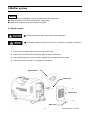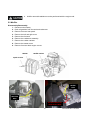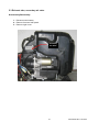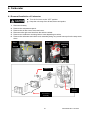
1
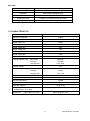
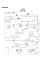
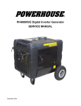
POWERHOUSE® POWERHOUSE POWER PRODUCTS PH2700PRi SHOP MANUAL Coast Distribution November, 2010 1 PH2700PRI SM 11-09-2010 Preface This manual covers the construction, function and servicing procedure of the POWERHOUSE® PH2700PRi generator, certificated by CARB. Careful observance of these instructions will result in better, safe service work. All information, illustrations, directions and specifications included in this publication are based on the latest product information available at the time of approval for printing. Coast Distribution Systems, Inc. reserves the right to make changes without incurring any obligation whatsoever. No part of this publication may be reproduced without written permission. 2 PH2700PRI SM 11-09-2010 Contents Preface ......................................................................................................................................................... 2 Contents ....................................................................................................................................................... 3 1. SPECIFICATIONS.................................................................................................................................... 5 1.1 SPECIFICATIONS ........................................................................................................................................ 5 1.2 CHARACTERISTICS ................................................................................................................................... 6 1.3 WIRING DIAGRAM .................................................................................................................................... 7 2.Service Information ................................................................................................................................... 8 2.1 The importance of proper servicing ............................................................................................................... 8 2.2 Important safety precautions.......................................................................................................................... 8 2.3 Service rules .................................................................................................................................................. 9 2.4 Serial number location ................................................................................................................................. 10 2.5 Engine maintenance standards ..................................................................................................................... 10 2.6 Motor ........................................................................................................................................................... 11 2.7 Torque values ............................................................................................................................................... 12 3.Trouble shooting ...................................................................................................................................... 13 3.1 General symptoms and possible causes ....................................................................................................... 13 3.2 Difficult cold starting ................................................................................................................................... 14 3.3 Hard starting ................................................................................................................................................ 15 3.4 Cylinder compression check ........................................................................................................................ 16 3.5 Ignition system............................................................................................................................................. 17 3.6 Engine oil level is low, but engine does not stop. ........................................................................................ 19 3.7 Engine stops running (Throttle is in the correct position) ........................................................................... 19 3.8 Engine speed can’t increase or is unstable (choke is in the correct position) .............................................. 20 3.9 Engine speed too high or too low ................................................................................................................ 20 3.10 Engine speed doesn’t increase with economy system “ON” and a load connected. .................................. 21 3.11 No or low AC output .................................................................................................................................. 21 3.12 Measuring stator output voltage while running ......................................................................................... 22 3.13 No DC output at battery charge receptacle ................................................................................................ 23 3.14 Battery will not charge ............................................................................................................................... 23 3.15 Voltage regulator ........................................................................................................................................ 24 3.16 Engine will not start or stop with remote. .................................................................................................. 25 3.17 Engine will start and then shut down. ........................................................................................................ 25 3.18 Engine will not shut off with ignition key, remote or stop button ............................................................. 26 3.19 No electric start. ......................................................................................................................................... 27 3.20 Parallel no output ....................................................................................................................................... 28 3.21 Parallel operation procedure: ..................................................................................................................... 29 3.22 Troubleshooting Parallel Operation ........................................................................................................... 31 3.23 Troubleshooting Parallel Operation (Cont.)............................................................................................... 32 4.Maintenance ............................................................................................................................................ 33 4.1 Maintenance schedule .................................................................................................................................. 33 4.2 Checking the oil level .................................................................................................................................. 34 4.3 Changing oil ................................................................................................................................................ 34 4.4 Checking for the low oil sensor ................................................................................................................... 35 3 PH2700PRI SM 11-09-2010 4.5 Air Cleaner................................................................................................................................................... 36 4.6 Spark plug .................................................................................................................................................... 37 4.7 Valve clearance ............................................................................................................................................ 38 4.8 Fuel tank ...................................................................................................................................................... 40 4.9 Evaporation Control..................................................................................................................................... 40 4.10 Fuel pump, primer bulb ............................................................................................................................. 41 5 Muffler system ......................................................................................................................................... 42 5.1 Spark arrestor ............................................................................................................................................... 42 5.2 Muffler ......................................................................................................................................................... 43 5.3 Exhaust tube, secondary air valve................................................................................................................ 44 6. Carburetor .............................................................................................................................................. 45 6.1 Removal/Installation of Carburetor ............................................................................................................. 45 6.2 Disassembly/Installation of Step motor ....................................................................................................... 46 6.3 Disassembly/Reassembly of Carburetor ...................................................................................................... 47 6.4 Step motor inspection .................................................................................................................................. 48 6.5 Automatic choke inspection/adjustment. ..................................................................................................... 49 7. Control panel .......................................................................................................................................... 50 7.1 Disassembly/Installation .............................................................................................................................. 50 8. Outer generator housing ........................................................................................................................ 51 8.1 Disassembly and installation of housing case .............................................................................................. 51 9. Recoil starter / Electric Starter / Ignition coil .......................................................................................... 52 9.1 Recoil starter/Disassembly/Reassembly ...................................................................................................... 52 9.2 Starter motor ................................................................................................................................................ 53 9.3 Starter relay.................................................................................................................................................. 54 9.4 Ignition coil.................................................................................................................................................. 55 9.5 Ignition coil/Disassembly ............................................................................................................................ 56 9.6 Adjustment ................................................................................................................................................... 56 10. Rotor/Stator disassembly / reassembly................................................................................................ 57 10.1 Disassembly/Reassembly........................................................................................................................... 57 10.2 Stator Inspection ........................................................................................................................................ 58 11. Exploded engine view .......................................................................................................................... 59 12. Valve cover/ Rocker arm ...................................................................................................................... 62 12.1 Disassembly/ Reassembly.......................................................................................................................... 62 12.2 Rocker Arm Inspection .............................................................................................................................. 63 12.3 Cam and cylinder head removal / Reassembly .......................................................................................... 64 12.4 Inspection, valves and valve springs.......................................................................................................... 67 12.5 Piston/Connection rod ............................................................................................................................... 68 4 PH2700PRI SM 11-09-2010 1. SPECIFICATIONS 1.1 SPECIFICATIONS Dimensions and weights Model PH2700PRI Overall Length 22.8 in. (579mm) Overall Width 13 in. (330mm) Overall Height 17 in. (432mm) Net Weight, with battery 80 lbs. (36kg) Engine Model 157F Type 4-stroke,OHC, single cylinder, Gasoline engine Displacement 150cc Bore x stroke 57.4×57.8 Maximum horsepower 5.2 Hp Compression ratio 9.2:1 Cooling system Forced air-cooled Ignition system Electronic Spark plug A7RTC Carburetor Horizontal, Float type Air cleaner Semi-dry type Governor Electronic control Lubrication system Pump Lube oil SAE 15W-40 (SF/SG grade or greater) Oil capacity 16 oz (0.5 L) Starting system Remote, Electric, & Recoil Stopping system Primary circuit ground Fuel used Automotive unleaded gasoline 5 PH2700PRI SM 11-09-2010 Alternator Alternator type Multi pole rotation type Alternator structure Self-ventilation drip-proof type Excitation Self-excitation (Magnet type) Phase Single phase Rotating direction Clockwise (Viewed from the generator) Frequency regulation AC-DC-AC conversion (Inverter type) 1.2 CHARACTERISTICS Model PH2700PRi Maximum output AC 2.7KVA Rated output AC 2.6KVA Rated output DC 100W Rated frequency 60HZ Rated voltage AC 120V Rated voltage DC 12V Rated current AC 21.7A Rated current DC 8.3A 1.0cosφ Power factor Voltage variation rate Momentary 10%max. Average 1.5%max. Average time 3 sec. max. Voltage stability ±1% Frequency variation rate Momentary 1%max. Average 1%max. Average time 1 sec. max. Frequency stability ±0.1% Insulation resistance 10MΩmin. AC circuit protector 2 x 20A DC circuit protector 10A Fuel tank capacity 1.4 gal (5.2L) Continuous running time 2.9 / 7.2 hours (at Rated load / at ¼ load) Noise level 58-67 dB @ 23‟ (7m) (Zero load to full load) 6 PH2700PRI SM 11-09-2010 1.3 WIRING DIAGRAM 7 PH2700PRI SM 11-09-2010 2.Service Information 2.1 The importance of proper servicing Proper servicing is essential to the safety of the operator and the reliability of the engine. Any error or oversight made by the technician while servicing can easily result in faulty operation, damage to the engine or injury to the operator. Improper servicing can cause an unsafe condition that can lead to serious injury or death. Follow the procedures and precautions in this shop manual carefully. Failure to follow maintenance instructions and precautions can cause you to be seriously hurt or killed. Follow the procedures and precautions in this shop manual carefully. Some of the most important precautions are given below. However, we cannot warn you of every conceivable hazard that can arise in performing maintenance or repairs. Only you can decide whether you should perform a given task. 2.2 Important safety precautions Be sure you have a clear understanding of all basic shop safety practices and that you are wearing appropriate clothing and safety equipment. When performing maintenance or repairs, be especially careful of the following: Read the instructions before you begin, and be sure you have the tools and skills required to perform the tasks safely. Be sure that the engine is off before you begin any maintenance or repairs. This will reduce the possibility of several hazards: a.) Be careful to avoid carbon monoxide poisoning from engine exhaust. b.) Make sure there is adequate ventilation whenever you run the engine. c.) Be careful to avoid burns from hot engine parts and hot exhaust. d.) Let the engine cool before you touch it. e.) Be careful to avoid injury from moving parts Do not run the engine unless the service manual instructs you to do so. When the engine is running, keep your hands, fingers, and clothing away from moving parts. To reduce the possibility of a fire or explosion, be careful when working around gasoline. Use only a nonflammable solvent, not gasoline, to clean parts. Keep all cigarettes, sparks, and flames away from fuel and all fuel-related parts. 8 PH2700PRI SM 11-09-2010 2.3 Service rules 1. Use genuine POWERHOUSE® or POWERHOUSE®-recommended parts and lubricants or their equivalents. Parts that do not meet POWERHOUSE® design specifications may damage the engine. 2. Always install new gaskets, O-rings, etc. when reassembling. 3. When tightening bolts or nuts, begin with larger-diameter or inner bolts first and tighten to the specified torque diagonally, unless a particular sequence is specified. 4. Clean parts in cleaning solvent upon disassembly. Lubricate any sliding surfaces before reassembly. 5. After reassembly, check all parts for proper installation and operation. 6. Many screws used in this machine are self-tapping. Be aware that cross-threading or over tightening these screws will strip the threads and damage the hole. 7. Use only metric tools when servicing this engine. Metric bolts, nuts and screws are not interchangeable with non metric fasteners. The use of incorrect tools and fasteners will damage the engine. ■ Electric precautions 1. Hold the connector body to disconnect the connector. Do not disconnect by pulling the wire harness. To disconnect the locking connector, be sure to unlock first, and then disconnect. 2. Check the connector terminals for bent pins, excessive stretching, missing terminals, or other abnormalities before connecting the connector. 3. To connect, insert the connector completely into the receptacle. If the connector is a locking type, be sure that it is locked securely. 4. Check the connector cover for cracks or other damage and make sure the connector female terminal fits snugly into the connector. Then, connect the connector securely. Check the connector terminal for rust. Remove any rust using an emery paper or equivalent material before connecting the connector. 5. Secure the harness clips in the specified locations on the frame, and clamp the wire harnesses. 6. Clamp the wire harnesses securely so that they do not interfere with rotating parts, moving parts or hot parts. 7. Route and connect the wire harnesses as shown in the service manual. Be sure that the harnesses are not loose, twisted or pulled tight. 8. Route the wire harnesses properly so that they do not contact with shape edges or corners, or the end of any bolts or screws. 9. If a wire harness contacts the end of any bolts or screws or sharp edges or corners, protect that part of the harness with a tube or by wrapping with an insulating tape. If the wire harness has a grommet, install the grommet securely. 10. Take care not to pinch the wire harnesses during installation of a part. If a wire harness has the damaged insulation, repair by winding with the electrician‟s insulating tape. 11. Before using the tester, carefully read the manufacturer‟s instructions and follow the instructions in this Service Manual. Be sure that the test unit‟s battery is fully charged and verify that the unit is operating correctly before you begin testing. 9 PH2700PRI SM 11-09-2010 2.4 Serial number location The generator‟s engine serial number identifies your particular unit and is required when ordering parts and accessories. The generator serial number is also used by your dealer and Coast Distribution for warranty administration and must be supplied before any work can be done. The serial number can be found stamped on the engine block above the oil dipstick. It is visible when the maintenance panel is removed. 2.5 Engine maintenance standards Part Item Engine Maximum speed without load Cylinder Sleeve I.D. Skirt O.D Piston Pin bore I.D. Piston pin O.D Height h Ring side clearance 1st ring Ring end clearance Width t Height h Piston ring Ring side clearance 2nd ring Ring end clearance Width t Height h Oil ring Ring side clearance Ring end clearance 10 Standard Service limit 5000±100rpm — 57.4000-57.4020mm 58.105mm (2.2598”-2.599” (2.2875”) 57.960-57.980mm 57.85mm (2.281”-2.282”) (2.277”) 15.002-15.008mm 15.05mm (0.5907”-0.5908 (0.5925”) 14.994-15.000mm 14.95mm (0.5903”-0.5905”) (0.588”) 0.97-0.99mm 0.87mm (0.0381”-0.0389”) (0.0342”) 0.02-0.06mm 0.15mm (0.0008”-0.0024”) (0.0059”) 0.15-0.25mm 1.0mm (0.0059”-0.0098”) (0.039”) 1.90-2.10mm 1.80mm (0.0748”-0.0826”) (0.0590”) 0.97-0.99mm 0.87mm (0.0381”-0.0389”) (0.0342”) 0.02-0.06mm 0.15mm (0.0008”-0.0024”) (0.0059”) 0.15-0.25mm 1.0mm (0.0059”-0.0098”) (0.039”) 2.0-2.3mm 1.8mm (0.0787”-0.0905”) (0.0590”) 1.85-1.96mm 1.75mm (0.0728”-0.0771”) (0.0688”) 0.03-0.18mm 0.24mm (0.001”-0.007”) (0.009”) 0.20-0.50mm 1.0mm (0.0078”-0.0196”) (0.039”) PH2700PRI SM 11-09-2010 Width t Connecting rod Small end I.D Stem O.D. EX Guide I.D. IN/EX Seat width IN/EX Outer spring Free length 15.08mm (0.590”-0.591”) (0.594”) ----- 4.975-4.99mm 4.92mm (0.1958”-0.1964”) (0.1937”) 4.955—4.970mm 4.90mm (0.1950”-0.1951”) (0.193”) 5.000—5.030mm 5.06mm (0.197”-0.198”) (0.199”) 1.0mm 2.0mm (0.039”) (0.079”) 35.5mm 33.8mm (1.397”) (1.330”) 32.8mm Inner spring Cam height 29.026-29.086mm 28.5mm (1.143”-1.145”) (1.104”) — 12mm — (0.472”) Pilot screw opening (Fixed) — N/A 0.6-0.7mm Gap Resistance (1.224”) (0.028”) Float height Spark plug 31.1mm (1.291”) 0.70mm Main jet Ignition coil 15.006-15.017mm (0.0059” ± 0.0008”) IN Carburetor (0.0748”) 0.15±0.02mm EX Cam wheel (0.0807”-0.0925”) (0.0039” ± 0.0008”) Valve clearance Valve spring 1.9mm 0.10±0.02mm IN Valves 2.05-2.35mm (0.024”-0.028”) — Primary side 0.045-0.070Ω — Second side 5-8k Ω — 2.6 Motor Part Item Wire color Standard(Ω) 120V DC winding Sub winding Main winding Resistance Resistance Resistance blue-blue white-white black-black-black 0.045-0.070 Ω 0.100-0.160 Ω 0.250-0.350 Ω 11 PH2700PRI SM 11-09-2010 2.7 Torque values Tightening torque Lbs-ft N·m N/A N/A 9.6-11 13-15 7.4-8.9 10-12 51.8-59.2 70-80 3.7-5.2 5-7 Item Specification Connection rod bolt Spark plug Crankcase cover Flywheel nut N/A M10*1*13 M6*75 M12*1.25 M5 Bolt, nut Standard torque M6 Blot, nut 6-7.4 8-10 M8 Bolt, nut 13.3-16.2 18-22 Note: Use standard torque values for fasteners that are not listed in this table. 12 PH2700PRI SM 11-09-2010 3.Trouble shooting 3.1 General symptoms and possible causes Fuel filter clogged Replace Battery Fuse Inspect / replace Fuel tank tube clogged Inspect / clean Fuel valve clogged Inspect / clean Carburetor faulty Inspect / clean Check valve / Choke pot faulty Inspect / repair or replace not start or Ignition coil faulty Inspect / replace hard starting Spark plug faulty Inspect / clean / replace Spark plug cap loose Tighten Low oil sensor faulty Inspect wiring / inspect sensor Ignition module Inspect Ignition winding faulty Inspect Throttle not opening properly Set in fully close or half close position Carburetor faulty Inspect / disassemble and clean Economy switch Inspect Throttle control motor (step motor) Inspect wiring / inspect motor Engine does Engine speed does not stabilize, too high or too low faulty Inverter unit faulty Inspect / replace Valve clearance misadjusted Readjust 13 PH2700PRI SM 11-09-2010 3.2 Difficult cold starting The choke on the PH2700PRi operates automatically. When the unit is off, the choke will return to the closed position. In some cases, the choke on the PH2700PRi may close too slowly or open too fast. Both conditions can cause difficulty starting the unit. Read below to see if one or both conditions are present. What to check: 1. Remove the maintenance cover (fig. 1) to view the choke system (fig. 2-A). Fig. 1 2. Make sure that there is sufficient fuel in the tank and the fuel valve is open. If the unit has been sitting for some time or has been run out of fuel, it may be necessary to pump the primer bulb several times to fill the fuel filter, ensuring fuel is getting to the carburetor. Maintenance 3. While cranking the engine over using the ignition key (Not the remote), watch the choke lever (fig. 3-A). The lever should begin to move to the left (Open) position as it is being pulled by the vacuum from the engine. Fig. 2 Cover A Choke opens too fast: 1. If the choke is being pulled open to fast, there will not be enough fuel drawn in to the intake manifold to start the engine. If after four starting attempts the unit fails to start, try holding the choke closed while cranking. If the unit now starts, shut the key off and allow the generator to cool down for several minutes. If after sitting for several minutes the unit is still hard to start without holding the choke closed, the check valve will need to be replaced. If the bar code number on your unit is 377055 (Fig. 4), kit # 69885 will then need to be installed. Fig. 3 Open Close A Choke closes too slowly: 1. If the choke opens properly but does not return to the closed position over an extended period of time, restarting can be difficult. The choke should normally return to the closed position in 2 seconds or less. If the choke stays open for more than 5 seconds, the check valve will need to be replaced. If the bar code number on your unit is 377055 (Fig. 4), kit # 69885 will then need to be installed. 14 Fig. 4 PH2700PRI SM 11-09-2010 3.3 Hard starting Check the fuel level. No fuel Add fuel and restart the engine. Sufficient fuel Loosen the drain screw and check whether fuel reached the carburetor. No fuel at carburetor Check fuel filter and fuel valve. Good spark Remove the spark plug and check for wet or fouled electrode. Dry Clean the electrode and restart, taking care that the choke is not closed too much. If flooding is severe, check the carburetor float valve. Wet Install the spark plug and ground the electrode. Check the spark. Check fuel lines and carburetor for any blockage or a stuck float. No spark or weak spark Perform the ignition system troubleshooting Good spark Install a compression gauge in the spark plug hole and check the cylinder compression by pulling the recoil starter rope several times Low cylinder compression 1. Check the valve clearance 2. Check for carbon deposits in the combustion chamber. 3. Check the valve cone and seat 4. Check for worn piston, piston ring or cylinder. Normal compression Install the spark plug securely. Restart the engine according to the starting procedure. 15 PH2700PRI SM 11-09-2010 3.4 Cylinder compression check 1. Remove the spark plug cap and spark plug. 2. Install a compression gauge in the spark plug hole. 3. Push the remote switch to the OFF position. 4. Turn the ignition switch to the start position and measure the cylinder compression. Cylinder compression 0.45Mpa (65 psi) /800rpm Pressure Gauge Remote Switch 16 PH2700PRI SM 11-09-2010 3.5 Ignition system Fill the oil reservoir to the correct level. Use A7RTC or equivalent spark plug. Spark plug inspection Don‟t pull the recoil starter or turn the ignition switch to “START” while touching the high tension wire. Turn off the fuel valve. Pull the recoil starter several times to release the unburned gas in the cylinder with the engine switch OFF. 1. Remove spark plug. 2. Install the spark plug into the plug cap. 3. Turn the ignition switch to the “ON” position. Attach the negative (—) electrode (i.e. threaded part) of the spark plug to your ground wire and pull the recoil starter rope to check the spark plug. Ground Wire Spark Plug Spark Plug Wire 17 PH2700PRI SM 11-09-2010 Measure the spark plug gap and perform the spark plug test. Standard clearance: 0.6-0.7mm (0.024”-0.028”) No spark Perform the spark test again using a new spark plug Good spark Replace the spark plug No spark Remove the control panel. Perform the spark test using a new indicator module. Good spark Replace the module No spark Good spark Check the ignition switch Replace the ignition switch No spark Disconnect the low oil sensor and perform spark test Good spark Replace the low oil sensor No spark Check the resistance of stator ignition winding Abnormal Replace the motor stator Normal Check the ignition coil resistance and high pressure cable, high pressure insulation cap. Abnormal Replace the ignition coil Normal Check ignition coil air gap Abnormal Readjust air gap Normal Inspect or replace wire harness. 18 PH2700PRI SM 11-09-2010 3.6 Engine oil level is low, but engine does not stop. Drain out oil completely, disconnect the oil sensor wire harness, and check the continuity between black wire and the chassis ground. (Page 30) No continuity Check and repair all wire connections. Replace the oil level alarm Continuity Ground the white lead from the indicator module to the engine block to ensure that the engine will stop when the low oil alarm lamp is lit. (Page 30) No continuity Repair or replace the wire harnesses Continuity Indicator module fault, replace the module. 3.7 Engine stops running (Throttle is in the correct position) Check the oil level and oil sensor Oil sensor Sufficient oil Check fuel level No fuel Fill the oil reservoir to the proper level and restart the engine Fill the tank with fuel and restart the engine Sufficient fuel Check the fuel valve and fuel filter for blockage Blocked Clear the fuel valve and replace the fuel filter Blocked Clear or replace the fuel supply hose Not blocked Check the fuel supply hose for blockage Not blocked Check the carburetor gasket for leakage Abnormal Tighten carburetor bolts or replace gasket as required Abnormal Refer to step motor inspection section in service manual Abnormal Readjust the coil clearance Normal Perform the throttle control system test Normal Check ignition coil Normal Measure the cylinder compression Abnormal 19 1. Check the valve clearance 2. Check the carbon deposit in combustion chamber 3. Check the piston, piston ring and cylinder for damage PH2700PRI SM 11-09-2010 3.8 Engine speed can’t increase or is unstable (choke is in the correct position) Blocked Check the fuel filter for blockage Replace fuel filter Not blocked Blocked Check the air filter element for blockage Clear the air filter element Not blocked Inspect spark arrestor for carbon build up Blocked Remove and clean carbon deposits. Abnormal Clear electrode, adjust clearance or replace the spark plug Not blocked Remove the spark plug and check the electrode clearance for carbon deposit Normal Check the carburetor and nozzle for blockage Blocked Disassemble and clear No blockage Check the carburetor gasket for leakage Abnormal Normal Measure the cylinder compression Abnormal Normal Tighten carburetor bolts or replace gasket as required 1. Check the valve clearance 2. Check the carbon deposit in combustion chamber 3. Check the piston, piston ring and cylinder for damage Perform the throttle control system test 3.9 Engine speed too high or too low Check the AC output Abnormal Perform the generator trouble shooting following the instruction of “No or low AC output” Normal Check the throttle control motor Abnormal Replace the throttle control motor Normal Check the Economy switch Abnormal Replace the Economy switch Normal Check Economy switch connection wire Abnormal Repair or replace the wire harness Normal Replace the inverter unit 20 PH2700PRI SM 11-09-2010 3.10 Engine speed doesn’t increase with economy system “ON” and a load connected. Check the AC output Abnormal Perform the generator troubleshooting following the instruction of “No or low AC output” Normal Check the step motor Abnormal Replace the step motor Normal Check the Economy switch Abnormal Replace the Economy switch Normal Check Economy switch connection wire Abnormal Repair or replace the wire harness Normal Replace the inverter unit 3.11 No or low AC output Is the overload indicator light ON? ON Disconnect the load, and restart the engine OFF Is the engine speed normal? Economy switch ON: 2300±100 rpm OFF:5000±100 rpm Abnormal Perform the throttle control system test Normal Stop the engine and check the AC receptacle Abnormal Replace the AC receptacle Normal Disconnect the 6P connector between the inverter and stator unit, pull the recoil starter with force, and measure the AC voltage between the black terminals and white terminal. Abnormal Black-Black-Black: >30V White-White: >1V 1. Check and repair stator wire harness or replace stator 2. Rotor inner magnetism decreases, replace the rotor Normal Measure stator output with unit running Abnormal Replace stator 21 PH2700PRI SM 11-09-2010 3.12 Measuring stator output voltage while running Inverter 6-Pin Stator Receptacle 6-Pin Stator Connector 1 4 2 3 White Sub Windings 3&6 6 Black Phase Wires, 1, 2 & 4 1. Unplug the connector from the inverter and start the engine, check voltage between pins 1 & 4, between pins 2 & 4, and between pins 1 & 2. Note, the engine will be running at a high RPM. 2. They should be approximately 300vac at each test with the engine running at high speed. If one or more of the three tests fail, the problem is either a damaged wire harness or a defective alternator. If the wire harness is the problem, look for and repair the damage. 3. If the alternator is the problem, the stator will need to be replaced. If all three tests are OK, the problem is probably the inverter. 22 PH2700PRI SM 11-09-2010 3.13 No DC output at battery charge receptacle Is the engine speed normal? Abnormal Perform the throttle control system test. Normal Check the DC circuit breaker Abnormal Reset DC circuit breaker Normal Abnormal Check the DC output Check the wire harness and all connections to and from the voltage regulator. Normal Abnormal Replace Battery charge cables Check battery charge cables 3.14 Battery will not charge Check battery connections Abnormal Clean and tighten all battery connections Normal Check the DC output at battery Abnormal Check all wire connections of the voltage regulator Normal Unplug the DC charge windings from the voltage regulator and measure the resistance. Resistance: 0.3 Ω +/- 10% Abnormal Check the wire harness, or replace the stator Normal Replace the voltage regulator DC Battery Charge Windings from Stator To the Voltage Regulator 23 PH2700PRI SM 11-09-2010 3.15 Voltage regulator Control panel harness Inverter Battery Chassis Ground Terminal Ignition Switch Voltage Regulator Starter Solenoid Stator Starter solenoid Chassis Ground Terminal 24 PH2700PRI SM 11-09-2010 3.16 Engine will not start or stop with remote. Does the red indicator light on the remote come on, when either the start or stop buttons are pushed No Replace the transmitter battery Yes Is there continuity at the remote rocker switch when it is in the on position No Replace rocker switch Yes With the engine running, disconnect the red wire from the battery and measure the voltage between the red wire and chassis ground. There should be 12-15 VDC coming from the regulator No Check ground wire between the voltage regulator, engine and chassis. Check voltage between ground wire from voltage regulator and red battery cable No voltage Replace Voltage regulator Yes Check 6-pin connection at the remote receiver Abnormal Repair or replace faulty connections OK Replace the remote transmitters and receiver 3.17 Engine will start and then shut down. This condition can affect the ignition switch, remote and manual start system What to check for: 1. Check engine oil level and fill to the proper level as required.. 2. If the low oil light comes on and the oil level is correct, refer to low oil sensor trouble shooting section. 3. Remove the front control panel and unplug the remote receiver. 4. If the unit will now start and continue to run replace the receiver and transmitters. Note, with the receiver unplugged, the generator will not shut off using the ignition switch. To shut down the unit, reconnect the receiver or turn off the fuel lever. 25 PH2700PRI SM 11-09-2010 3.18 Engine will not shut off with ignition key, remote or stop button This section is only valid for units from Bar Code Label purchase order number 377055. The Purchase order number can be found on the bar code label located on the bottom of the generator. See illustration here. For safety, we recommend turning off the fuel valve instead of pulling off the spark plug wire. What to check for: 1. Turn on the fuel valve and restart the engine. 2. Using a volt ohm meter check the battery charge receptacle. There should be between 12 and 14 volts DC. If no voltage is present check all connections to and from the voltage regulator. 3. Check to make sure that there is a good ground between the voltage regulator ground wire, engine and control panel. A bad ground will prevent the unit from shutting down properly. 4. Locate and unplug the two blue wires between the stator and voltage regulator. With the engine running the voltage from the stator must be 12-20VAC. If no voltage is present the stator is defective. If voltage is present replace the voltage regulator. 5. If voltage is present at the control panel, make sure that the remote switch on the control panel is in the off position. 6. Check the 6-pin connection between the remote receiver and control panel looking for any loose or broken wires. If no problems are found replace the remote receiver. Control panel harness Inverter Battery Chassis Ground Terminal Ignition Switch Voltage Regulator Starter Solenoid Stator Starter solenoid Chassis Ground Terminal 26 PH2700PRI SM 11-09-2010 3.19 No electric start. Abnormal Measure battery voltage Charge battery Normal Abnormal Check the ignition switch Replace ignition switch Normal Abnormal Check the ground between the relay, engine and control panel Repair ground Normal Abnormal Replace the starter relay Check the starter relay Normal Abnormal Replace the starter motor Check the starter motor Normal Check, repair or change main harness wires Cable from Starter Solenoid Starter Motor Terminal Starter Motor Battery Terminal Voltage Regulator Start Wire from Ignition Switch Chassis Ground Solenoid 27 PH2700PRI SM 11-09-2010 3.20 Parallel no output Check whether the two generators could work well separately. Abnormal Is one of the over load indicating light on? Off Perform single generator troubleshooting 1. Check the parallel output cable 2. Check the parallel output terminal On Disconnect all loads and reset the inverter Normal Replace parallel kit Turn “OFF” both generators and disconnect all the electrical devices from the generators. Plug the cables from the parallel kit into each of the units. Two separate PH2700PRi models can run in parallel to increase the total output to a maximum load of 5400 W (Rated output, 5200 W). You can also run a PH2700PRi and a PH2100PRi in parallel. The maximum output will be 4200 W (Rated output, 4000 W). Never Connect or Disconnect the parallel kit cables from the generators while running. Doing so will cause perminate damage not covered under warranty. The required output of the electrical appliance cannot exceed the rated output of parallel generators. The special parallel cables for the PH2700PRi and PH2100PRi is only applicable to the parallel operation of two POWERHOUSE® generators. This kit cannot be used for paralleling three or more generators or running two different brands of generators. ONLY the POWERHOUSE® Dual Generator Parallel Kit and cables may be connected to the parallel signal port. DO NOT CONNECT TO OTHER ELECTRONICS OR USE OTHER CABLES. Permanent damage not covered by the warranty will occur. Start both generators and confirm that both green "RUN" lights are illuminated. Note, The Economy Switch automatically turns off when running in parallel. 28 PH2700PRI SM 11-09-2010 3.21 Parallel operation procedure: 1. Prepare two POWERHOUSE® generators for operation. 2. Connect the 15-pin signal cable between the parallel kit and each generator and secured with the thumb screws. 3. Connect the 3-pin parallel cable from the parallel kit into each generator making sure that the cables for generator „A‟ and generator „B‟ are not switched. 4. Start both generators and confirm that both green "RUN" lights are illuminated on the generators and on the front panel of the parallel kit. 5. The Economy Switch may be used as long as the Economy switch setting of both generators is the same. 6. The starting procedure is the same as the normal starting procedure. 7. Securely plug the electrical appliance plug into either or both of the parallel receptacles and switch on the electrical appliance. The required output of the electrical appliance cannot exceed the rated output of the generators. The special parallel cable for the PH2700PRI and PH2100PRi is only applicable to the parallel operation of two POWERHOUSE generators. It cannot be used for paralleling three or more generators or running two different brands of generators. Be sure to only use parallel output cable for parallel running. Don't disconnect the parallel output cable during parallel operation. 3-Pin Parallel Cable ‘B’ 3-Pin Parallel Cable ‘A’ 29 PH2700PRI SM 11-09-2010 20 and 30 amp Circuit Breakers 120V-30 amp Locking Receptacle Output Indicator (Green) 120V Short Indicator (Red) Grounding Terminal Overload Reset Button (Green) 120V-20 amp Receptacle To prevent electrical shock from faulty appliances, the parallel kit should be grounded. Connect a length of heavy cable between the parallel ground terminal and an external ground source. 1. During normal operating conditions, the output indicator lights (Green) will remain illuminated. 2. If the generators are overloaded (in excess of 5200W when using two PH2700PRi units) the overload indicator light (red) will flash slowly on only one generator. The indicator lights on the other unit and the parallel kit will all be off. 3. At this time, there will be no electrical output from the parallel panel and the connected appliance or load will be shut off. 4. Remove all electrical loads from the generators and/or parallel kit and then determine and correct the cause of the overload. 5. To reset the overload condition (Red light), press and release the (Green) overload reset button on the parallel panel. The (Green) indicator lights should be illuminated on both generators and on the parallel panel within 15 seconds. 30 PH2700PRI SM 11-09-2010 3.22 Troubleshooting Parallel Operation Problem Condition Cause Correction Flashing The red overload light on one of The load (Wattage) Remove all loads from the overload the generators is flashing slowly. has exceeded the parallel panel and the light. There are no indicator lights on the capacity of one or generators and press the green other generator or parallel panel. both generators. reset button on the parallel There is no AC output from either panel. The green indicator light of the generators or parallel panel. on both generators and the Both engines are running at a slow parallel kit should come on idle. within 15 seconds. If the reset is pushed without correcting the cause for the overload, the system will try to reset briefly but the units will again shut down. Repeatedly pressing the reset button without correcting the overload condition may cause permanent damage to the generators and/or parallel kit. Short The red (Short) indicator light on The hot and neutral Remove all loads from the indicator the parallel panel is on. The output wires between parallel panel and the light on the indicator lights on both generators the parallel kit and generators and check the parallel are all off. appliances are appliances for shorts. Repair or panel from either of the generators or shorted, or there is a replace shorted appliances as parallel panel. Both engines are short in the appliance. needed. There is no AC output running at a slow idle. Press the green reset button on the parallel panel. The green indicator light on both generators and the parallel kit should come on within 15 seconds. Repeatedly pressing the reset button without correcting the short circuit may cause permanent damage to the generators and/or parallel kit. 31 PH2700PRI SM 11-09-2010 3.23 Troubleshooting Parallel Operation (Cont.) Problem No indicator lights (Red or Green) Condition Cause Correction There is no AC output Loose or disconnected Remove all loads from the parallel panel from either of the power cord between the and the generators. generators or parallel parallel kit and parallel panel. Both engines power socket on the Reconnect or plug in the power cord from are running at a slow generator. the parallel kit to the power socket on the generator. The green indicator light idle. should come back on in approximately 15 seconds. If not, press the green reset button on the parallel panel. No AC The green light on both An excessive load is output from generators and parallel connected to either the panel are on. The 30A or 20A receptacle generators are running on the parallel panel. parallel panel Remove or reduce excessive loads. Reset circuit breakers. at high idle. 32 PH2700PRI SM 11-09-2010 4.Maintenance 4.1 Maintenance schedule Regular Service period (1). Perform at every indicated month or operating hour interval, whichever occurs first. Item Maintenance Procedure Check Engine Oil Spark Plug Spark Arrester Valve clearance Every 3 Months or 50 HRS Every 6 Months Or 100 HRS Every Year Or 300 HRS O O O O Clean O (2) Clean - adjust O Clean Check Fuel Filter Each Use Change Check Air cleaner First Month Or 20 HRS O O Replace O (2) Check - adjust Fuel tank & strainer Clean Fuel line Check O (3) O (2) Every 2-years (Replace as necessary) (3) Note: (1) For commercial use, operation hours are determined by proper maintenance. (2) Service more frequently when operating in dusty areas, every 10 hrs or every day. (3) Service by POWERHOUSE authorized agency, unless correct tools or professional specialist is available. Do service according to the manual. 33 PH2700PRI SM 11-09-2010 4.2 Checking the oil level Stop the engine and check the oil level, be sure to put the engine on a flat surface when checking. 1. Loosen the screw on the engine maintenance cover and remove the cover. 2. Remove the oil filler cap and check for oil level. 3. If the oil level is low, add oil until it reaches the edge of the oil filler port. 4.3 Changing oil Drain the oil while the engine is still warm to assure rapid and complete draining. Make sure to turn the engine switch and fuel lever OFF before draining. 1. Loosen the screw on the engine maintenance cover and remove the maintenance cover. 2. Remove the oil filler cap. 3. Install the oil drain pipe. 4. Drain dirty oil into a container. Allow enough time for the oil to drain completely. 5. Refill with the recommended oil, and check the oil level. 6. Reinstall the access panel and tighten the screws securely. Engine oil capacity: 16oz. (0.50L) Drain Pipe Upper Level Upper Level Lower Level Dipstick 34 PH2700PRI SM 11-09-2010 Please dispose of used motor oil in a manner that is compatible with the environment and local disposal regulations. Do not throw it in the trash or pour it on the ground. 4.4 Checking for the low oil sensor 1. Remove the maintenance cover and locate the oil sensor lead which is below and too the right of the dipstick. 2. Disconnect the low oil sensor when the engine is running. 3. Ground the white lead (Female connector) from the indicator module to the engine block, to verify that the engine will stop when the low oil alarm lamp is lit. 4. After confirming that the engine oil is at the proper level, test the continuity between the (Male connector) from the oil sensor and the case of the engine. No continuity indicates a normal condition. 5. Continuity between the oil sensor lead and engine when the oil is drained from the engine indicates a normal condition. No continuity after the oil has been drained would indicate a faulty oil sensor or a damaged wire that must be repaired or replaced. Failure to do so can lead to permanent damage if the engine runs low on oil. Female Connector to module Oil Sensor Connector Male Connector Check Continuity between the Male connector from the Oil sensor Lead and Ground 35 PH2700PRI SM 11-09-2010 4.5 Air Cleaner Inspection/Cleaning: 1. Loosen the panel screw and remove the side maintenance panel. 2. Remove the air cleaner cover and remove the fine filter element. 3. Wash the element in a non-flammable or high flash point solvent and dry it thoroughly. 4. Soak fine element in clean engine oil and squeeze out the excess oil. 5. Reinstall the fine air cleaner element and the air cleaner cover. Tighten the cover screws securely. 6. Reinstall the maintenance panel and tighten the screw securely. Air Cleaner Case Air Cleaner Element leaner Air CleanereC Air Cleaner Case Cover Screw Air Cleaner Screws Maintenance Cover A dirty air cleaner will restrict air flow to the carburetor, reducing engine performance. If the engine is operated in dusty areas, clean the air cleaner more often than specified in the Maintenance Schedule. Never run the engine without an element or the filter is damaged, as it will do great harm to the engine. 36 PH2700PRI SM 11-09-2010 4.6 Spark plug Inspection/Cleaning: 1. Remove the spark plug cap and remove the spark plug. 2. Remove carbon or other deposits with a plug cleaner or stiff ire brush. Check the sealing washer for damage. 3. Measure the plug resistance; replace the spark plug if the measurement is not within the value shown. Spark plug resistance 3-9KΩ 4. Measure the plug gap with a wire-type feeler gauge. Adjust by bending the side electrode Spark plug clearance 0.6-0.7mm (0.024”-0.028”) Standard spark plug A7RTC 0. 6- 0. 7 5. Install the plug finger tight to seat the washer, and then tighten with a plug wrench. Torque valve is 9.6-11 lbs-ft (13-15 Nm) 37 PH2700PRI SM 11-09-2010 4.7 Valve clearance Valve clearance inspection and adjustment must be performed with the engine cold. Inspection/Adjustment: 1. 2. 3. 4. 5. 6. 7. 8. 9. 10. Disconnect the battery. Drain all gasoline from the fuel tank and carburetor. Remove the front and rear panels. Remove the left and right covers. Remove the fuel tank. Remove the carburetor assembly. Remove the starter motor. Remove the carbon canister. Remove the front and back engine covers. Remove the muffler. Valve Cover 11. Turn the rotor to set the piston at top dead center of the compression stroke. The timing mark of camshaft should be vertical to the cylinder head seal, check whether the inlet and exhaust valve are closed. Timing Mark 38 PH2700PRI SM 11-09-2010 Insert a feeler gauge between the rocker arm and the valve and measure the valve clearance. IN Valve clearance 0.10+/- 0.002mm (0.0039” ± 0.0008”) EX 0.15 +/- 0.002mm (0.0059” ± 0.0008”) 12. If adjustment is necessary, proceed as follows. a. Loosen the adjusting screw lock nut and adjust the valve clearance by turning the adjusting screw in or out. b. Secure the adjusting screw with a socket wrench and tighten the lock nut to the specified torque. c. After tightening the lock nut, check the valve clearance again. 13. Clean the cylinder block and cylinder head cover. Adjustment Screw Lock Nut Feeler Gauge 14. Replace the rubber seal. 15. Install the removed parts in the reverse order of removal. Rubber Seal 39 PH2700PRI SM 11-09-2010 4.8 Fuel tank Gasoline is highly flammable and explosive. You can be burned or seriously injured when handling gasoline. Keep heat, sparks, and flame away from the work area. Wipe up spills immediately. Cleaning: 1. Disconnect the battery. 2. Drain all gasoline from the tank and carburetor. 3. Remove the front and rear panels. 4. Remove the left cover. 5. Remove all hoses from the tank, clean it with cleaning solvent and allow the fuel tank to dry thoroughly. 6. After cleaning, reconnect all hoses. 7. Install the removed parts in the reverse order of removal. 8. Fill the fuel tank with gasoline and check the fuel hoses for gasoline leaks. 4.9 Evaporation Control Fuel Tank Vent Air Filter To Air Filter Fuel Tank Carbon Canister 40 PH2700PRI SM 11-09-2010 4.10 Fuel pump, primer bulb Gasoline is highly flammable and explosive. You can be burned or seriously injured when handling gasoline. Keep heat, sparks, and flame away from the work area. Wipe up spills immediately. 1. Disconnect the battery. 2. Remove front and rear panel. 3. Remove the left cover. 4. Drain all gasoline from the fuel tank and carburetor. 5. Check the fuel tubing for deterioration, cracks and gas leaks. If there is any abnormality in the fuel tubing, replace it. 6. Check the primer bulb and diaphragm tube for deterioration, crack or gas leaks. If there is any abnormality in the primer bulb or diaphragm tube, replace it. 7. Check to see whether water or foreign material has accumulated in the fuel pump. 8. If there is water or foreign material accumulated in the pump, replace the fuel pump. 9. Check the fuel valve and make sure there is no obstruction when open. Clean or replace as required. 10. After reassembly check all hoses and connections for fuel leaks. Primmer Bulb Fuel Valve To Intake manifold To Carburetor To Gas Tank Fuel Pump 41 PH2700PRI SM 11-09-2010 5 Muffler system Caution ■ Muffler removal / installation must be performed with the engine cold. ■ Drain all gasoline from the fuel tank before disassembly. ■ Keep the unit away from all heat, flame and sparks. 5.1 Spark arrestor Do the performance after engine has cooled completely. ■ The spark arrester must be serviced every 100 hours to maintain its efficiency. 1. Remove the four M6 screws and remove the muffler grill. 2. Remove the two M4 screws holding the spark arrester to the muffler. 3. Use a stiff wire brush to remove carbon deposits from the spark arrester screen. 4. Inspect the screen for holes, and replace it if necessary. Spark Arrestor M4 Screws Muffler Grill M6 Screws 42 PH2700PRI SM 11-09-2010 Muffler removal/installation must be performed with the engine cold. 5.2 Muffler Disassembly/Reassembly 1. Disconnect the battery. 2. Drain all gasoline from the tank and carburetor. 3. Remove front and rear panel. 4. Remove the left and right cover 5. Remove the fuel tank. 6. Remove the carburetor assembly. 7. Remove the carbon canister. 8. Remove the starter motor. 9. Remove front and back engine covers. Muffler Muffler Gasket Spark Arrestor Muffler Bolts Manifold Bolts “DO NOT” Remove the Chain Tension Bolts 43 PH2700PRI SM 11-09-2010 5.3 Exhaust tube, secondary air valve Disassembly/Reassembly 1. Disconnect the battery. 2. Remove front and rear panel. 3. Remove right cover Secondary Air Valve 44 PH2700PRI SM 11-09-2010 6. Carburetor 6.1 Removal/Installation of Carburetor 1. 2. 3. 4. 5. 6. Turn the fuel lever to the “OFF” position. Keep the unit away from all heat, flame and sparks. Disconnect battery. Remove the maintenance panel. Remove the air filter cover screw and cover. Disconnect the right vent hose from the carbon canister. Remove two carburetor mounting bolts or nuts depending on series. Remove the carburetor and choke as an assembly being very careful not to pull on the step motor wires. Fig. 1 Fig. 2 Mounting Screw Cover Bolts Right Vent Hose Choke Pot Carbon Canister Air Cleaner assembly 45 PH2700PRI SM 11-09-2010 6.2 Disassembly/Installation of Step motor t 步进电机机盖 步进电机 Step motor Step motor base 步进电机座 拔叉弹簧 Fork spring Disassembly: 拆卸: 拆卸时用手捏牢, Carefully remove 以防弹簧丢失。 the spring and fork from the throttle lever. Fork 拔叉 拔叉 Fork 油门杆 Throttle level Fork spring 拔叉弹簧 Idle怠速调整限位帽 adjusting cap 46 PH2700PRI SM 11-09-2010 6.3 Disassembly/Reassembly of Carburetor Fork Choke lever 阻风门杆 拨叉 拨叉弹簧 Fork spring 阻风门片 Choke plate Idle 怠速调整限位帽 adjusting cap Mixed ratio adjusting screw, 混合比调节螺丝 (Not adjustable on 出厂前位置已确 CARB 定,units) 不可调节 Carburetor block 本体 Emulsifier tube Installation: clear the foreign matters with 泡沫管 compressed 组装: air before 先用压缩空气清除通 installation. Pay attention to 路中的脏物再安装。 the installation direction Needle seat 针座 Fuel control needle 控油针 Installation: check the end and 组装: 先对端部的磨损、弹簧的动 spring before installation 作进行检查,再进行安装。 注意安装方向。 控油针弹簧 Needle spring Main jet Installation: 主量孔 Clear the foreign matters with 组装: compressed air before 先用压缩空气 installation. Pay attention to 清除通路中的 the 脏物再安装。 installation direction Seal ring for fuel cup 油杯密封圈 浮子销 Float pin 浮子 组装: 安装后应当用手指触 Float 动,对其动作确认。 Fuel cup 油杯 油杯锁紧螺丝密封圈 Seal ring Drain screw 油杯放油螺栓 Installation: check the 组装: fuel leakage before 安装后确认没有燃油 installation 漏出。 油杯螺栓 Fuel cup bolt 组装: Installation: check the 安装后确认没有燃油 fuel leakage 漏出。 before installation 47 PH2700PRI SM 11-09-2010 6.4 Step motor inspection Make sure to check the step motor connection on the inverter for any debris, damaged or bent pins Measure the resistance of the step motor lead-out wire. Replace the step motor if the resistance exceeds the ranges shown below. Standard resistance 1 2 3 4 1-blue - 2-white:50-55Ω 3-red - 4-black:50-55Ω 48 PH2700PRI SM 11-09-2010 6.5 Automatic choke inspection/adjustment. The choke on the PH2700PRi operates automatically. When the unit is off, the choke will return to the closed position 1. The automatic choke consists of the backpressure check valve and the vacuum pot, figure 1. 2. Items to check if the automatic choke fails to operate. a. Check all vacuum hoses for cracks or damage, replace as necessary. b. Check the backpressure check valve for leaks or a defective diaphragm. c. Check all choke linkage to insure it operates smoothly and that the choke closes and opens fully. d. To insure that the choke is closing fully, remove the filter cover and check the choke. Loosen the set screw and make sure that the butterfly closes completely, and then retighten, figure 2. e. To check the vacuum pot for leaks, disconnect the vacuum hose from the barbed fitting. Move the choke lever to the open position and block off the barbed fitting on the choke pot, figure 3. The choke should stay in the open position as long as the fitting is closed off. Fig. 1 Choke Pot Check Valve Vacuum Hose to Manifold Fig. 2 Fig. 3 Choke Lever Barbed Fitting Close Set Screw Open Choke Rod Choke Plate, Open Choke Plate, Closed 20A AC Circ 49 PH2700PRI SM 11-09-2010 7. Control panel 7.1 Disassembly/Installation 1. Remove six M4 panel screws. Panel Screws Indicator Module Parallel Power Socket Ignition Switch Parallel Signal Port Module Cover Button Guard Stop / Reset Buttons 120V~20A Circuit Breakers DC Battery Charge Receptacle 120V~20A Duplex, Split DC Circuit Breaker 50 Economy / Remote Switches PH2700PRI SM 11-09-2010 8. Outer generator housing 8.1 Disassembly and installation of housing case Exhaust Grill Maintenance Cover Inverter Pull Cord Handle Battery Spark Plug Access Primmer Bulb Right Side Case Control Panel Fuel Pump Panel Frame Fuel Valve Battery Access Cover Handle / Axle Assembly Fuel Lever Rubber Feet 51 PH2700PRI SM 11-09-2010 9. Recoil starter / Electric Starter / Ignition coil Caution ■ Drain all gasoline from the fuel tank before disassembly. ■ Keep the unit away from all heat, flame and sparks. 9.1 Recoil starter/Disassembly/Reassembly 1. 2. 3. 4. 5. 6. 7. Disconnect the battery. Remove front and rear panels. Remove the left and right covers. Drain all gasoline from the fuel tank. Remove the fuel tank and the inverter. Remove (3) M6 flange bolts and the recoil starter. Reinstall the inverter side covers and end panels. Battery Box Inverter 52 PH2700PRI SM 11-09-2010 9.2 Starter motor ● Disassembly 1. Disconnect the battery. 2. Remove front and rear panels. 3. Remove the left and right covers 4. Using and 8mm socket remove 2-mounting bolt. 5. Remove the starter and the cable. Starter Relay Cable Screw Mounting Bolts 53 PH2700PRI SM 11-09-2010 9.3 Starter relay 1. Using a volt ohm meter, check the resistances of the electromagnetic coil of the starter relay by connecting the red positive lead to the ¼” spade and the black negative lead to the metal body of the relay. Resistance 5.4 Ω +/- 10% 2. Check the function of the start relay by connecting 12 volts + to the ¼” spade terminal and 12 volts negative to the metal base or body. There should be a clicking sound as the relay is activated. While the relay remains activated, use the volt ohm meter check continuity between the two lugs. If there is no continuity the relay is defective. 3. Note, there must only be continuity between the battery and the starter terminals when the relay is activated. Checking Resistance Checking Continuity Connect 12volts + Connect 12volt Negative. 54 PH2700PRI SM 11-09-2010 9.4 Ignition coil Inspection 1. Remove the control panel and locate the 2-pin primary coil plug with a Blue and Black wire and unplug it from the control panel. 2. Attach the two leads of tester to the Blue and Black wires and measure the primary resistance of the ignition coil. 3. If there is no resistance, check for continuity between the black wire and chassis ground. If there is no continuity repair or correct as necessary. 4. Replace the coil if there is no resistance or the value is outside of the values shown. Primary resistance 2.3 Ω +/- 10% The blue wire should be connected to the coil The black wire should be connected to the chassis ground 1. Check continuity between the blue and black wires if installed. 2-Pin Coil Connector 2. If not Installed, check continuity between the blue wire and coil bracket. Check the secondary resistance between the blue wire and spark plug cap 5. To check the secondary resistance, attach one lead of the tester to the black wire of the primary plug of the ignition coil and the other lead to the spark plug cap. 6. If there is no resistance remove the spark plug cap and check the lead itself. 7. Replace the spark plug cap or coil if there is no resistance or the value is outside of the values shown. Secondary resistance 12.7 k Ω +/- 10% 55 PH2700PRI SM 11-09-2010 9.5 Ignition coil/Disassembly 1. Disconnect the battery. 2. Remove front and rear panel. 3. Remove the left and right cover 4. Remove the fuel tank and the inverter. 5. Remove the inlet fan cover. 9.6 Adjustment 1. Adjust the clearance between the ignition coil and the outer magnet trigger of the rotor. 2. Loosen the ignition coil bolts and Insert a feeler gauge between the ignition coil and the permanent magnet of the rotor, (Both sides need to be adjusted equally) and retighten the bolts. 3. Rotate the rotor to make sure there is interference with the flyweights. Ignition coil clearance 0.5-0.75mm Ignition Coil Rotor Permanent magnet 56 PH2700PRI SM 11-09-2010 10. Rotor/Stator disassembly / reassembly 10.1 Disassembly/Reassembly 1. Remove the following parts: Front cover, control panel. Rear cover. Right/left side covers. Fuel tank. Battery box. Inverter. Fan cover Starter cup and fan M12 flange nut Ignition coil Rotor M5 Stator bolts Stator Ignition Coil Stator Assembly Rotor Assembly M5 Flange Bolts M12 Flange Nut Fan Starter cup 57 PH2700PRI SM 11-09-2010 10.2 Stator Inspection (1) DC charging winding Measure the resistance between the two blue terminals. Resistance Blue-Blue 0.045-0.070 Ω (3) Sub winding Measure the resistance between the two sub winding terminals. Resistance White-White 0.100-0.160 Ω (4) Main winding Measure the resistance between each of the main winding terminals. Resistance Black-Black-Black 0.250-0.350 Ω Main Windings, (Black Sub Windings, (White) DC Battery Charge Windings, (Blue) 58 PH2700PRI SM 11-09-2010 11. Exploded engine view 59 PH2700PRI SM 11-09-2010 Item No. 1 2 2-1 3 4 5 6 7 8 9 10 11 12 13 13-1 14 15 16 17 18 19 20 21 22 23 24 25 26 27 28 Description 157 Engine ERP No. M6 x 75 hexagon screw Front engine cover Front engine seal M8 nut Chain for oil pump Chain wheel for oil pump M6 x 25 bolt Oil pump Crankcase gasket Crank case bushing Front crankcase Oil passage cover M3 x 5 roundhead screw Oil dipstick O'-Ring, dipstick (not shown) Crankshaft assembly Crankcase gasket Crank case bushing M5 x12 bolt O'-Ring, Low oil sensor Low oil sensor Rear crankcase "O" style sealing ring Tie bar bolt Rear oil seal Timing chain guide Timing chain Timing chain guide Retainer ring Located pin for piston 60 03050611 76115 040906 03060115 09070116 09070117 03050241 09070115 09070164 04030265 76113 09010342 03050802 68150 09070202 09070126 09070164 04030265 03050221 04070108 71046 76023 09070129-31 03050313 040907 09070111 09070112 09070109 09070139 09070102 Stock No. 69700 69709 69710 69712 69349 69714 69694 69309 69437 69694 69430 69328 69706 69715 69701 69702 69705 69708 Qty 7 1 1 1 1 1 2 1 1 2 1 1 2 1 1 1 1 2 3 1 1 1 1 1 1 1 1 1 2 1 PH2700PRI SM 11-09-2010 Item No. 29 30 31 32 33 34 35 36 37 38 39 40 41 42 43 44 45 46 47&48 49 50 51 52 55 56 57 59 60 Description 157 Engine ERP No. Piston w/rings Cylinder gasket Locating bushing, head M8 x 195 threaded stud M8 x 185 threaded stud Cylinder sleeve Locating bushing, head Head gasket Intake valve Cylinder head Spark plug, A7RTC M6 X 5 roundhead bolt M6 x 20 bolt Tensioner Gasket, tensioner Exhaust valve Washer Valve seal Valve spring Kit, 2100 & 2700 Valve seat retainer Lock catch for valve M6 x 100 bolt Camshaft Rocker assy. (includes 53 & 54) M8 nut Valve cover gasket Valve cover/PCV Assy. M6 x 25 bolt 61 09010513 915009 04030264 03050603 03050601 09010516 04030264 09070107 09070122 09010517 09080114 03050327 03050223 09070113 09070114 09070123 09070121 09070118 09070120 09070119 09070125 03050226 09070128 09070133 03060115 09070110 77050 03050241 Stock No. 69698 60045 69685 69683 69412 69686 69352 69688 69690 69670 69674 69674 69677 69681 69682 69669 69644 69709 69667 69349 Qty 1 1 2 2 2 1 2 1 1 1 1 1 2 1 1 1 1 1 2 2 4 2 1 1 4 1 1 4 PH2700PRI SM 11-09-2010 12. Valve cover/ Rocker arm 12.1 Disassembly/ Reassembly Remove the four bolts and valve cover. 1. Turn the rotor to set the piston at top dead center of the compression stroke. 2. The timing mark of camshaft should be vertical to the cylinder head seal, check whether the inlet and exhaust valve are closed. 3. Remove 4- rocker arm bolts and carefully remove the rocker arm assembly Timing Mark Alignment Sleeves 62 PH2700PRI SM 11-09-2010 12.2 Rocker Arm Inspection ● Rocker arm outer diameter Standard Service limit 9.96-9.975mm ( ) 9.953mm ( ) ● Rocker arm inner diameter of inlet/exhaust valve Standard(mm) Service limit(mm) 10.000-10.015 ( ) 10.040 ( ) 63 PH2700PRI SM 11-09-2010 12.3 Cam and cylinder head removal / Reassembly 1. Turn the rotor to set the piston at top dead center of the compression stroke. 2. The timing mark of camshaft should be vertical to the cylinder head seal. Make sure the inlet and exhaust valve are closed. 3. Remove the timing chain tensioner. 4. Secure the timing chain with safety wire to prevent it from falling into the crank case. 5. Lift and remove the cam assembly from the head. 6. Carefully inspect the cam lobes, bearings and decompression operation. ● Cam height Standard(mm) Service limit(mm) 29.026-29.086 mm (1.143”-1.145”) 29.15 mm (1.104”) Timing Chain Tensioner ON Cam Bearings Intake Cam Decompression Fly Weight OFF Exhaust Cam Decompression “ON” 64 Decompression “OFF” PH2700PRI SM 11-09-2010 7. While holding the safety wire that is attached to the timing chain, carefully remove the cylinder head and gasket. Timing Chain Head Gasket Reassembly: 8. Replace the head gasket. 9. Follow the reverse procedure to reassemble. Caution Make sure that the piston is at top dead center which can also be confirmed by locating the crank shaft keyway in the vertical (Upright) position. Install the chain onto the cam gear making sure that the timing mark is straight up before installing the rocker arm assembly. Timing Mark Timing Mark Crankshaft Keyway 65 PH2700PRI SM 11-09-2010 Reinstalling the timing chain tensioner: 10. Remove the adjustment cover screw and „O‟-ring. 11. Replace gasket. 12. Using a small flat blade screw driver rotate the spring loaded adjustment screw clockwise to retract the plunger. 13. Constant clockwise tension must be applied to the center screw until the tensioner is flush with the gasket before it is released. Rotate tension Screw Clockwise to Retract plunger Adjustment Screw Cover and ‘O’-Ring Normal Position The Plunger must be kept in the retracted position while reinstalling. 66 PH2700PRI SM 11-09-2010 12.4 Inspection, valves and valve springs ● Free length of valve spring Spring Standard Service limit Small 35.5mm (1.397”) 31.1mm (1.224”) Large 32.8mm (1.291”) 33.8mm (1.330”) ● Valve seat width Standard Service limit 1.0mm (0.039”) 2.0mm (0.079”) ● Valve stem outer diameter Standard Service limit Intake valve 4.975-4.99mm (0.1958”-0.1964”) 4.92mm (0.1937”) Exhaust valve 4.955-4.970mm (0.1950”-0.1951”) 4.90mm (0.193”) 67 PH2700PRI SM 11-09-2010 12.5 Piston/Connection rod Assembly of piston ring ? ? ? ? ( ? ? Caution ● Make sure the rings are installed with the manufacturer‟s label up. ● Make sure the 1st ring and 2nd ring are not interchanged. ● Make sure the piston rings are free to move after installation. st 1? ring ? ? ? ( ? ? 2?nd ? ring Oil ring ● Stagger each piston ring gap 120°from each of the other rings. Manufacturers 厂家标记 Label 第一道环 1st ring 第二道环 2nd ring Oil油环 ring 活塞 Piston 活塞销 Piston pin 活塞销卡环 Piston pin clip ring 组装: Installation: set the front end in the piston 将前端置于活塞的槽处,用尖嘴钳夹 groove, and clamp the other end. Install 住另一端, 边转动边安装到槽内。 the ring clip by revolving. Make sure that 不要使卡环的开口对着活塞销孔的缺 口处。 the gap of the ring clip is not in line with the groove in the piston pin hole. 连杆 卡环 Clip ring Connection rod Installation: 组装: The larger side of the 将大端部较长的一侧朝向活塞的 “ connection ” 指向的右侧装入活塞 。 rod must be aligned with the △ label on the piston. 68 PH2700PRI SM 11-09-2010 ● Cylinder inner diameter Standard 57.4000-57.4020mm (2.2598”-2.599” Service limit(mm) 58.105mm (2.2875”) ● Piston skirt outer diameter Standard 57.960-57.980mm (2.281”-2.282”) Service limit 57.85mm (2.277”) Piston pin clip 10mm ● Side clearance of piston ring 1 and 2 Ring Standard 0.02-0.06mm (0.0008”-0.0024”) Service limit 0.15mm (0.0059”) Oil Ring 0.03-0.18mm (0.001”-0.007”) 0.24mm (0.009”) st nd 69 PH2700PRI SM 11-09-2010 ● Piston ring end clearance Locate the piston ring into cylinder with piston top, and measure the piston end clearance. 1 and 2 Ring Standard 0.15-0.25mm (0.0059”-0.0098”) Service limit 1.0mm (0.039”) Oil Rings 0.20-0.50mm (0.0078”-0.0196”) 1.0mm (0.039”) 1 and 2 Ring Standard 0.97-0.99mm (0.0381”-0.0389”) Service limit 0.87mm (0.0342”) Oil Rings 1.85-1.96mm (0.0728”-0.0771”) 1.75mm (0.0688”) st nd ● Piston ring height st nd 70 PH2700PRI SM 11-09-2010 ● Piston pin outer diameter Standard Service limit(mm) 14.994-15.008mm (0.5903-0.5905”) 14.95mm (0.5925”) ● Piston pin hole inner diameter Standard Service limit 15.002-15.008mm (0.5907-0.5908”) 15.05mm (0.5925”) ● Connection rod small end inner diameter Standard Service limit 15.006-15.017mm (0.590-0.5991”) 15.08mm (0.594”) 71 PH2700PRI SM 11-09-2010