1
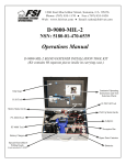
CAMERA CONTROL UNIT
CCU-TX7
CCU-TX7P
CAMERA OPERATION UNIT
COU-TX7
SDI OUTPUT BOARD
DXBK-701
SERVICE MANUAL
Volume 1 1st Edition (Revised 2)
! WARNING
This manual is intended for qualified service personnel only.
To reduce the risk of electric shock, fire or injury, do not perform any servicing other than that
contained in the operating instructions unless you are qualified to do so. Refer all servicing to
qualified service personnel.
! WARNUNG
Die Anleitung ist nur für qualifiziertes Fachpersonal bestimmt.
Alle Wartungsarbeiten dürfen nur von qualifiziertem Fachpersonal ausgeführt werden. Um die
Gefahr eines elektrischen Schlages, Feuergefahr und Verletzungen zu vermeiden, sind bei
Wartungsarbeiten strikt die Angaben in der Anleitung zu befolgen. Andere als die angegeben
Wartungsarbeiten dürfen nur von Personen ausgeführt werden, die eine spezielle Befähigung
dazu besitzen.
! AVERTISSEMENT
Ce manual est destiné uniquement aux personnes compétentes en charge de l’entretien. Afin
de réduire les risques de décharge électrique, d’incendie ou de blessure n’effectuer que les
réparations indiquées dans le mode d’emploi à moins d’être qualifié pour en effectuer d’autres.
Pour toute réparation faire appel à une personne compétente uniquement.
CCU-TX7 (E)/V1
MANUAL STRUCTURE
Purpose of this manual
This manual is the Service Manual Vol. 1 of the CAMERA CONTROL UNIT CCU-TX7
(for NTSC) and CCU-TX7P (for PAL), CAMERA OPERATION UNIT COU-TX7 and SDI
OUTPUT BOARD DXBK-701.
This manual contains the operation manual related to the operations of this equipment,
the replacement of the parts and adjustments.
Related manuals
In addition to this Service Manual Vol. 1, the following manual is provided.
. Service Manual Vol. 2
Part No. 9-977-286-23
Contains semiconductor pin assignments, parts lists, block diagrams, board illustrations
and schematic diagrams.
CCU-TX7 (E)/V1
1
TABLE OF CONTENTS
1. OPERATING INSTRUCTIONS
1-1. CCU-TX7/TX7P ............................................................................................ 1-1
1-2. DXBK-701 ................................................................................................... 1-13
2. INSTALLATION
2-1. CONNECTORS AND CABLES ................................................................... 2-1
2-1-1. Connector Input/Output Signals ............................................................. 2-1
2-1-2. Connection Connector ............................................................................ 2-4
2-1-3. Wiring Diagram for Cable ...................................................................... 2-4
2-2. MAKING OF WF MODE CONNECTOR .................................................... 2-4
2-3. COAX CONNECTOR ................................................................................... 2-5
2-4. OPERATING ENVIRONMENT ................................................................... 2-5
2-5. MOUNTING ON 19-INCH RACK ............................................................... 2-6
2-6. SWITCH FUNCTIONS ON BOARD ........................................................... 2-7
3. SERVICE INFORMATION
3-1. BOARD LAYOUT ......................................................................................... 3-1
3-2. DISASSEMBLY/INSTALLATION OF MAIN PART ................................. 3-1
3-2-1. Removal of Cabinet ................................................................................ 3-1
3-2-2. Replacement of Switching Regulator ..................................................... 3-2
3-2-3. Replacement of Fan ................................................................................ 3-3
3-2-4. Removal of COU-TX7 ........................................................................... 3-3
3-3. CIRCUIT DESCRIPTION ............................................................................. 3-4
CT-181 board ....................................................................................................... 3-4
AA-90 board ........................................................................................................ 3-4
YD-26 board ........................................................................................................ 3-4
ES-20 board .......................................................................................................... 3-4
AU-234 board ...................................................................................................... 3-4
IO-140 board ........................................................................................................ 3-4
SDI-44 board (DXBK-701) ................................................................................. 3-4
3-4. EXTENSION OF DXBK-701 (SDI-44 BOARD) ......................................... 3-5
4. ADJUSTMENT
4-1. PREPARATION ............................................................................................ 4-1
4-1-1. Equipment Required ............................................................................... 4-1
4-1-2. Fixture ..................................................................................................... 4-1
4-1-3. Notes on Adjustment .............................................................................. 4-1
4-1-4. Switch settings ........................................................................................ 4-1
4-1-5. Connections ............................................................................................ 4-2
4-2. VIDEO SIGNAL SYSTEM ADJUSTMENT ................................................ 4-3
4-2-1. Sub-carrier Frequency Check ................................................................. 4-3
4-2-2. CAM H Phase Adjustment ..................................................................... 4-3
4-2-3. H Phase Adjustment ............................................................................... 4-4
CCU-TX7 (E)/V1
3
4-2-4. SYNC Phase Adjustment ....................................................................... 4-4
4-2-5. INT SC Phase Adjustment ...................................................................... 4-5
4-2-6. Y CLAMP Adjustment ........................................................................... 4-5
4-2-7. Y OUT (COMP) Level Adjustment ....................................................... 4-6
4-2-8. Y OUT (VBS) Level Adjustment .......................................................... 4-6
4-2-9. R-Y/B-Y White Black Balance Adjustment ........................................... 4-7
4-2-10. G Level Adjustment ............................................................................... 4-7
4-2-11. R Level Adjustment ................................................................................ 4-8
4-2-12. B Level Adjustment ................................................................................ 4-8
4-2-13. WF OUT R/B DC OFFSET Adjustment ................................................ 4-9
4-2-14. Carrier Balance Adjustment ................................................................... 4-9
4-2-15. Color Vector Adjustment ..................................................................... 4-10
4-2-16. R-Y/B-Y OUT Level Adjustment ........................................................ 4-10
4-2-17. VBS OUT Level Adjustment ............................................................... 4-11
4-2-18. STAIR CASE Adjustment .................................................................... 4-11
4-2-19. WIDE ID Level Adjustment ................................................................. 4-12
4-3. Y CABLE COMPENSATION SYSTEM ADJUSTMENT ......................... 4-13
4-3-1. SYNC SEP Adjustment ........................................................................ 4-13
4-3-2. BLACK Pulse Width Adjustment ........................................................ 4-13
4-3-3. SYNC Sample Hold Pulse Width Adjustment ..................................... 4-14
4-3-4. 22.5 MHz VCO DC Set Adjustment .................................................... 4-14
4-3-5. Sample Pulse Width Adjustment .......................................................... 4-15
4-3-6. Sample Pulse V Gate Width Adjustment ............................................. 4-15
4-3-7. 22.5 MHz Carrier Level Adjustment .................................................... 4-16
4-3-8. Y DEMOD Carrier Balance Adjustment .............................................. 4-16
4-3-9. Y OFFSET Adjustment ........................................................................ 4-17
4-3-10. Y 90˚ Adjustment ................................................................................. 4-17
4-3-11. Y 1st AGC Adjustment ........................................................................ 4-17
4-3-12. Y Output Level Adjustment ................................................................. 4-18
4-4. CHROMA CABLE COMPENSATION SYSTEM ADJUSTMENT .......... 4-18
4-4-1. 45 MHz Carrier Level Adjustment ....................................................... 4-18
4-4-2. C PLL Set Adjustment .......................................................................... 4-19
4-4-3. B-Y DEMOD Carrier Balance Adjustment .......................................... 4-19
4-4-4. B-Y Crosstalk Adjustment ................................................................... 4-20
4-4-5. C 1st AGC Adjustment ......................................................................... 4-20
4-4-6. B-Y OUT Level Adjustment ................................................................ 4-21
4-4-7. R-Y DEMOD Carrier Balance Adjustment .......................................... 4-21
4-4-8. R-Y Crosstalk Adjustment ................................................................... 4-22
4-4-9. R-Y OUT Level Adjustment ................................................................ 4-22
4-5. RETURN VIDEO CABLE COMPENSATION SYSTEM
ADJUSTMENT ............................................................................................ 4-23
4-5-1. Return Video Carrier Frequency Adjustment ....................................... 4-23
4-5-2. Return Video Deviation Adjustment .................................................... 4-23
4-6. PROMPT VIDEO CABLE COMPENSATION SYSTEM
ADJUSTMENT ............................................................................................ 4-24
4-6-1. TX PROMPT VIDEO Demodulation Adjustment ............................... 4-24
4-6-2. RX PROMPT VIDEO Demod. Adjustment ......................................... 4-25
4-6-3. RX PROMPT VIDEO RF AGC Adjustment ....................................... 4-26
4-6-4. RX PROMPT VIDEO Level Adjustment ............................................ 4-27
4
CCU-TX7 (E)/V1
4-7. TRIAX INTERFACE SYSTEM ADJUSTMENT ....................................... 4-27
4-7-1. Frequency Set Adjustment ................................................................... 4-27
4-7-2. INCOM Deviation Adjustment ............................................................ 4-28
4-7-3. PGM Deviation Adjustment ................................................................. 4-28
4-7-4. INCOM Demodulation Adjustment ..................................................... 4-29
4-7-5. INCOM Level Adjustment ................................................................... 4-29
4-7-6. MIC 1 Demodulation Adjustment ........................................................ 4-30
4-7-7. MIC 1 Level Adjustment ...................................................................... 4-30
4-7-8. MIC 2 Demodulation Adjustment ........................................................ 4-31
4-7-9. MIC 2 Level Adjustment ...................................................................... 4-31
4-7-10. CAM DATA Demodulation Adjustment ............................................. 4-32
4-7-11. CAM TONE Adjustment ...................................................................... 4-32
CCU-TX7 (E)/V1
5
Operating Instructions
Before operating the unit, please read this manual
thoroughly and retain it for future reference.
CCU-TX7/TX7P
1997 by Sony Corporation
SECTION 1
OPERATING INSTRUCTIONS
Camera Control
Unit
1-1. CCU-TX7/TX7P
CCU-TX7 (E)/V1
3-859-845-12(1)
1-1
1-2
Table of Contents
For the customers in the USA
WARNING
To prevent fire or shock hazard, do not
expose the unit to rain or moisture.
This equipment has been tested and found to comply with
the limits for a Class A digital device, pursuant to Part 15 of
the FCC Rules. These limits are designed to provide
reasonable protection against harmful interference when the
equipment is operated in a commercial environment. This
equipment generates, uses, and can radiate radio frequency
energy and, if not installed and used in accordance with the
instruction manual, may cause harmful interference to radio
communications. Operation of this equipment in a residential
area is likely to cause harmful interference in which case the
user will be required to correct the interference at his own
expense.
You are cautioned that any changes or modifications not
expressly approved in this manual could void your authority
to operate this equipment.
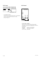
Over view ............................................................................ 4
Product Features .................................................................. 4
Connections ......................................................................... 5
Installing the Camera Operation Unit ................................. 7
Location and Function of Par t s ....................................... 8
Front Panel .......................................................................... 8
Rear Panel ......................................................................... 14
Internal Board Switches and Knobs .................................. 17
Notes on Use ................................................................... 20
Specifications .................................................................. 21
This device requires shielded interface cables to comply with
FCC emission limits.
This symbol is intended to alert the user to the
presence of uninsulated “dangerous voltage”
within the product’s enclosure that may be of
sufficient magnitude to constitute a risk of
electric shock to persons.
This symbol is intended to alert the user to the
presence of important operating and
maintenance (servicing) instructions in the
literature accompanying the appliance.
Owner’s Record
The model and serial numbers are located at the rear.
Record the serial number in the space provided below.
Refer to these numbers whenever you call upon your Sony
dealer regarding this product.
Model No.
Serial No.
CCU-TX7 (E)/V1
2
3
CCU-TX7 (E)/V1
Over
viewview
Over
Pr oduct Features
The CCU-TX7/TX7P is a camera control unit that
connects to DXC-637 Series and DXC-D30 Series
Color Video Cameras via the CA-TX7/TX7P Camera
Adaptor.
This product’s features are described below.
Full-featured signal transfer functions
• The CCU-TX7/TX7P is able to transfer wideband
component video signals. (Y signals at 9 MHz or
above, and R–Y and B–Y signals at 4.5 MHz or
above)
• When using a triaxial cable, audio signals can be
transferred up to 750 meters (2461 feet) (when cable
diameter is 8.5 mm (11/ 32 inch)) or 1,500 meters (4921
feet) (when cable diameter is 14.5 mm (19/32 inch)).
• Transfer functions are provided for the following
signals.
Return video, teleprompter signal, microphone audio,
program audio, red tally and green tally signals
• An intercom switch is also provided.
Flexibly adaptable camera control functions
• The optional COU-TX7 Camera Operation Unit,
which can be installed on the CCU-TX7/TX7P’s
front panel, enables video camera operations to be
controlled from the CCU-TX7/TX7P.
• When several CCU-TX7/TX7P units are connected in
parallel, the optional RCP-TX7 Remote Control
Panel can be used to control video camera operations
as well as the color balance between cameras.
• An RS-232C connector is provided for the CCUTX7/TX7P, allowing a personal computer to be
connected for computer-based control of video
camera operations.
Wide array of input/output signals
The input and output connectors provided for the
CCU-TX7/TX7P include those for outputting such
signals as a composite video signal (VBS), component
video signals (switchable to RGB), SDI signals, and
video signals for video and waveform monitors, for
inputting a reference signal for external
synchronization.
Rack mountable
Two CCU-TX7/TX7P units can be installed side by
side in the optional RMM-TXC7 Rack Mount Bracket.
4
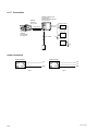
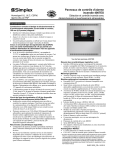
Connections
Examples of how to connect other devices to this unit
are shown in the following.
• Some of the video camera’s switches and buttons
may not operate while the CCU-TX7/TX7P is
connected to it.
Notes
For details, see the operation instructions for the video
camera or camera adaptor.
• Be sure to power the CCU-TX7/TX7P off before
inserting or removing the triaxial cable connector.
When using one CCU-TX7/TX7P unit
Out
In
Control console
In
In
Headset
In/Out
Headset
CA-TX7/TX7P
DXC-D30/D30P
Y/R–Y/B–Y,1)
R/G/B,Y/C
INTERCOM/
TALLY
MIC
OUT
RETURN
VIDEO
VBS
INTERCOM (front panel)
Reference sync signal
GENLOCK
Triaxial cable
CAMERA
PROMPT
VIDEO
Teleprompter signal
CCA-7 cable
DC IN
REMOTE
DC power
source 2)
CCU-TX7/TX7P
3)
PIX
WF
SYNC
AC IN
CCU/CAMERA
VIDEO
IN
AC power cord
(supplied)
AC power source 2)
VIDEO
IN
REF
IN
RCP-TX7
Video monitor
Waveform monitor
1) Y/R–Y/B–Y, R/G/B, and Y/C outputs are switchable.
2) Use either AC or DC power source.
3) This illustration shows the CCU-TX7.
5
1-3
1-4
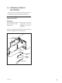
Over view
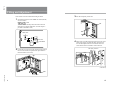
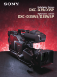
Installing the Camera Operation Unit
When using two CCU-TX7/TX7P units
Switcher, video
monitor, etc.
The following describes how to fit the optional COUTX7 Camera Operation Unit to the CCU-TX7/TX7P’s
front panel.
DXC-D30/D30P
VCR
Y/R–Y/B–Y,R/G/B,Y/C 1)
Open the CCU-TX7/TX7P’s
front panel.
2
Remove the blank panel and
the connector cap.
Reference sync signal
GENLOCK
CA-TX7/TX7P
Triaxial cable
1
Chroma keyer
VBS
CAMERA
RETURN VIDEO
Return video signal
PROMPT VIDEO
Teleprompter signal
CCA-7 cable
REMOTE
PROMPT
VIDEO
CCU-TX7/TX7P 3)
RETURN
VIDEO
CCU/CAMERA
RS232C
(For power sources,
see the connections
illustrated for the unit
shown below.)
GENLOCK
Switcher, video
monitor, etc.
DXC-D30/D30P
Stopper
Connector cap
Blank panel
VCR
Y/R–Y/B–Y,R/G/B,Y/C 1)
RCP-TX7
VBS
Chroma keyer
GEN
LOCK
CA-TX7/TX7P
Triaxial cable
CAMERA
RETURN
VIDEO
3
PROMPT
VIDEO
CCA-7 cable
REMOTE
DC IN
CCU/CAMERA
CCU-TX7/
TX7P 3)
SDI
OUT4)
RS232C
AC IN
AC power cord
(supplied)
Monitor with SDI input
1)
2)
3)
4)
6
Y/R–Y/B–Y, R/G/B, and Y/C outputs are switchable.
Use either AC or DC power source.
This illustration shows the CCU-TX7.
Using the SDI OUT connectors requires the optional
DXBK-701 board.
Flat cable
DC power
source 2)
RCP-TX7
Personal computer
(When the RCP-TX7s are
not connected.)
Attach the camera operation
unit to the front panel and
connect the flat cable to the
connector.
Camera
operation unit
AC power source 2)
4
Close the front panel and
fasten the screws.
VCR with SDI input
Waveform monitor
with SDI input
Switcher with SDI input
7
CCU-TX7 (E)/V1
CCU-TX7 (E)/V1
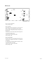
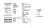
Location
and Function
of Par t s
Location
and Function
of Parts
Various switches, adjustment knobs, and connectors
are located on the front panel, rear panel, and also on
the edges of internal boards.
CCU-TX7/TX7P switches and knobs
You can then talk with the operator via the intercom.
This button also lights when the CALL button is
pressed on the camera adaptor or remote control panel.
1 TALLY lamp
TALLY
CABLE ALARM
SHORT
2 CABLE ALARM indicator
OPEN
Front P anel
CALL
For description of how to install the camera operation unit,
see “Installing the Camera Operation Unit” (page 7).
From the front panel, you can operate the CCU-TX7/
TX7P’s switches and knobs as well as the camera
operation unit’s switches and knobs (when the optional
COU-TX7 Camera Operation Unit has been installed).
4 INTERCOM audio input/output and setting
section
MIC switch
3 CALL button
CAMERA
POWER
INTERCOM
INTERCOM
MIC
ON
MIC
ON
LINE
CH1
LINE
CH1
PRIV
ON
OFF
INTERCOM
PRIV
CH2
PGM
OFF
INTERCOM
4 INTERCOM audio input/
output and setting section
5 CAMERA POWER switch
and indicator
OFF
CCU-TX7/TX7P switches and knobs
(see page 9)
PUSH
POWER
LINE switch
CH2
PGM
PGM knob
INTERCOM knob
PUSH
Camera operation unit switches and knobs
(see page 10)
INTERCOM connector
6 POWER switch and
indicator
TALLY
CABLE ALARM
OPEN
SHORT
OUTPUT
OPERATE
LOCK
PART
FULL
SHUTTER
SKIN
DETAIL
CALL
CAMERA
POWER
INTERCOM
LINE
CH1
MIC
ON
OFF
INTERCOM
CH2
PGM
TLCS
M.GAMMA
Hz
C.SCAN
ON
OFF
ON
OFF
DETAIL
WHITE/BLACK BALANCE
AUTO
WHITE
PRIV
ON
GAIN
HIGH
MID
LOW
CAM
BARS
AUTO
ATW
PRE
MANUAL
BLACK
MANUAL
OFF
BLACK
KNEE
AUTO
POWER
MASTER
BLACK
WHITE
IRIS
1 TALLY lamp
The lamp lights red when a red tally signal is received
and green when a green tally signal is received.
It also lights red when the CALL button is pressed on
the CA-TX7/TX7P Camera Adaptor or RCP-TX7
Remote Control Panel connected to this unit.
The camera number plate (provided) can be attached to
this lamp.
AUTO
PUSH
PRESET
1
MANUAL
A
1
A
2 CABLE ALARM indicator
SHORT: this indicator lights when an overcurrent
occurs in the triaxial cable connected to the
CAMERA connector on the rear panel.
OPEN: this indicator lights when there is no triaxial
cable connected to the CAMERA connector on
the rear panel or when the current flowing in the
connected triaxial cable is excessively small.
3 CALL button
When you press this button, it lights along with the red
TALLY lamps and CALL buttons on the video
camera, camera adaptor, and remote control panel
connected to this unit. This function can be used to call
the video camera or remote control panel operator.
8
INTERCOM connector (XLR 5-pin): Use this to
connect a headset.
INTERCOM (intercom level) knob: Use this to
adjust the intercom sound volume.
PGM (program audio level) knob: Use this to
adjust the sound volume when monitoring
program audio via a headset.
MIC switch: Use this switch to turn the headset’s
microphone ON or OFF.
LINE switch: Use this switch to select the channel
for intercom signals that are input and output via
the INTERCOM connector.
• CH1: Connects to channel 1
• CH2: Connects to channel 2
• PRIV: Does not connect to channel 1 or
channel 2. Instead, the intercom operates only
between this unit and the connected video
camera.
5 CAMERA POWER switch and indicator
When the POWER switch is on, use this switch to
switch the power on and off to the video camera and
camera adaptor connected to this unit. The indicator
lights when this switch is turned on powering the
camera adaptor.
6 POWER switch and indicator
This switches the power to this unit on or off. The
indicator lights when the power is on.
9
1-5
1-6
Location and Function of Par t s
3 SHUTTER setting section
Camera operation unit switches and knobs
4 WHITE/BLACK BALANCE control section
Display
1 OUTPUT switch
7 GAIN switch
OUTPUT
OPERATE
2 OPERATE switch
LOCK
PART
FULL
ATW button
WHITE/BLACK BALANCE
8 TLCS switch
SKIN
DETAIL
AUTO
WHITE
AUTO
ATW
PRE
M.GAMMA
9 M. GAMMA knob
Hz
C.SCAN
ON
OFF
WHITE AUTO/PRE/MANUAL switch
Hz
C.SCAN
ON
OFF
TLCS
HIGH
MID
LOW
CAM
BARS
SHUTTER
3 SHUTTER setting
section
GAIN
BLACK AUTO/
WHITE/BLACK switch and
MANUAL
indicators
switch
SHUTTER
ON
$ button and 4 button
MANUAL
BLACK
MANUAL
SHUTTER switch
OFF
BLACK
0 SKIN DETAIL switch
DETAIL
WHITE
WHITE/BLACK BALANCE
AUTO
WHITE
MANUAL
BLACK
AUTO
ATW
!¡ DETAIL knob
PRE
4 WHITE/BLACK BALANCE
control section
MANUAL
ON
BLACK
KNEE
AUTO
MASTER
BLACK
WHITE
5 KNEE switch
PRESET
1
2
3
4
IRIS
AUTO
!£ DIP switch
MANUAL
!™ IRIS control section
6 MASTER BLACK knob
The camera operation unit’s switches and knobs are
used to set and adjust video camera functions.
For details about the video camera functions and settings,
refer to operating instructions for your video camera.
1 OUTPUT switch
Use this switch to select the video to be output from
this unit.
CAM: Image being shot via video camera
BARS: Color bars generated by this unit
10
2 OPERATE (operation range setting) switch
Use this switch to set the operation range of the
camera operation unit.
LOCK: This setting disables all of the camera
operation unit’s functions.
PART: This setting enables only the IRIS control
section and MASTER BLACK knob to be
operated.
FULL: This setting enables all of the camera
operation unit’s functions to be used. Settings
changed while this switch was set to LOCK
become valid when this switch is set to FULL.
SHUTTER switch: Use this switch to select a
shutter setting. This switch does not function
when the TLCS switch is on.
• C. SCAN: This activates the clear scan function.
• ON: This activates the normal shutter function.
• OFF: This turns off the shutter.
$ button and 4 button: When the SHUTTER
switch is set to either C. SCAN or ON, pressing
one of these buttons changes the shutter speed or
clear scan frequency as described below.
• When SHUTTER switch is set to C. SCAN
Pressing and holding one of these buttons
gradually reduces ($ button) or increases (4
button) the clear scan frequency.
• When SHUTTER switch is set to ON
Each time one of these buttons is pressed, the
shutter speed is reduced ($ button) or increased
(4 button) by one step.
If you press both of these buttons at once, it
resets the clear scan frequency or shutter speed
(depending on the SHUTTER switch’s position)
to their factory settings.
Display: This displays the clear scan frequency
when the SHUTTER switch is set to C. SCAN or
the shutter speed when it is set to ON. “OFF” is
displayed here when the SHUTTER switch is set
to the OFF position.
When the TLCS switch is on, the display is blank.
WHITE knob
BLACK knob
WHITE knob (blue)
BLACK knob (red)
(red)
(blue)
BLACK AUTO/MANUAL switch
Use this switch to select whether to automatically
(AUTO) or manually (MANUAL) adjust the black
balance.
(When a DXC-637 series video camera is connected,
this switch is invalid and the black balance mode is
determined by the position of the WHITE AUTO/PRE/
MANUAL switch.)
WHITE/BLACK (white/black balance
adjustment) switch and indicators
When the WHITE AUTO/PRE/MANUAL switch is
set to AUTO, press this switch to the WHITE position
to automatically adjust the white balance.
When the BLACK AUTO/MANUAL switch is set to
AUTO, press this switch to the BLACK position to
automatically adjust the black balance.
The indicator by the WHITE or BLACK position
blinks at a one-second interval while the white balance
or black balance is being automatically adjusted. When
the automatic adjustment is completed, it stays lit for
about ten seconds, then goes out. If the automatic
adjustment fails, it blinks at a half-second interval for
about ten seconds and then goes out.
11
CCU-TX7 (E)/V1
CCU-TX7 (E)/V1
Location and Function of Par t s
WHITE AUTO/PRE/MANUAL (white balance
auto/preset/manual) switch
Use this switch to select the white balance adjustment
mode. This switch does not function while the ATW
function is being used (while the ATW button is lit).
AUTO: This sets auto adjustment mode. It enables
the white balance to be automatically adjusted
using the WHITE/BLACK switch.
(When a DXC-637 series video camera is
connected: this also sets auto adjustment mode
for the black balance. The black balance can be
automatically adjusted even while the ATW
function is being used.)
PRE: This sets preset mode. The white balance is
maintained at the preset value.
(When a DXC-637 series video camera is
connected: this also sets auto adjustment mode
for the black balance. The black balance can be
automatically adjusted even while the ATW
function is being used.)
MANUAL: Sets manual adjustment mode. It
enables the white balance to be manually adjusted
using the WHITE knob (red) and WHITE knob
(blue).
(When a DXC-637 series video camera is
connected: this also sets manual adjustment mode
for the black balance. The black balance can be
adjusted manually even while the ATW function
is being used.)
ATW (auto tracing white balance) button
Press this button (which lights up when pressed) to
have the white balance adjusted automatically when
lighting conditions change.
BLACK (black balance) knob (red)
When the BLACK AUTO/MANUAL switch is set to
MANUAL, this knob can be used to adjust the black
level of the R signal.
BLACK (black balance) knob (blue)
When the BLACK AUTO/MANUAL switch is set to
MANUAL, this knob can be used to adjust the black
level of the B signal.
WHITE (white balance) knob (blue)
When the WHITE AUTO/PRE/MANUAL switch is
set to MANUAL, this knob can be used to adjust the
gain of the B signal.
!™ IRIS control section
IRIS AUTO/MANUAL switch
IRIS
5 KNEE switch
Use this switch to adjust the knee setting.
AUTO: Knee is automatically adjusted
PRESET: Knee is adjusted to preset value
6 MASTER BLACK knob
This adjusts the master black (master pedestal level)
setting. The click position of the knob provides a
typical setting.
AUTO
!£ DIP switch
Use the four switches numbered 1 to 4 to make the
following settings.
No.1 OFF/No.2 OFF Standard color matrix setting
(This setting has no effect when a
DXC-D30 series video camera is
connected.)
No.1 OFF/No.2 ON
MANUAL
No.1 ON/No.2 OFF
Color matrix set for fluorescent
lighting (FL).
(This setting has no effect when a
DXC-D30 series video camera is
connected.)
No.1 ON/No.2 ON
Color matrix set for color emphasis
(H.SAT).
(This setting has no effect when a
DXC-D30 series video camera is
connected.)
No.3 ON
EVS function set on for the shutter.
(Has priority over the SHUTTER
switch setting on the camera
operation unit.)
No.4 ON
Date and time display set on for the
output picture.
Iris adjustment knob
7 GAIN switch
Use this switch to set any of three video amp gain
levels (HIGH, MID, or LOW). The gain value
corresponding to these levels can be set using a menu
on the video camera.
IRIS AUTO/MANUAL switch
Use this switch to select between AUTO and
MANUAL iris adjustment modes. Be sure that the
IRIS switch on the video camera is set to AUTO.
AUTO: Iris is automatically adjusted.
MANUAL: Iris is adjusted with the iris adjustment
knob.
8 TLCS (total level control system) switch
Press this switch to turn the total level control system
on or off. The switch lights when it is turned on. When
this switch is on, settings made with the GAIN switch
and SHUTTER switch are ignored.
(This function cannot be used when a DXC-637 series
video camera is connected.)
Iris adjustment knob
When the IRIS AUTO/MANUAL switch is set to
MANUAL, this knob can be used to manually adjust
the iris.
When the IRIS AUTO/MANUAL switch is set to
AUTO, this knob can be used to manually fine-tune
the automatic iris adjustment.
9 M. GAMMA (master gamma) knob
Use this knob to adjust the gamma curve. The click
position of the knob provides a typical setting.
(This function cannot be used when a DXC-637 series
video camera is connected.)
0 SKIN DETAIL switch
Use this switch to turn the skin detail correction
function on or off.
(This function cannot be used when a DXC-637 series
video camera is connected.)
!¡ DETAIL knob
Use this knob to adjust the detail level. The click
position of the know proides a typical setting.
WHITE (white balance) knob (red)
When the WHITE AUTO/PRE/MANUAL switch is
set to MANUAL, this knob can be used to adjust the
gain of the R signal.
12
13
1-7
1-8
Location and Function of Par t s
Rear Panel
9 OUTPUT connectors
CAMERA
PGM IN
OUTPUT
VBS1
!º Fan
1 R/R-Y/C 2
INPUT
1 PGM IN connector
GENLOCK
ON
VBS2
1 G/Y/Y 2
PIX
1 B/B-Y 2
OFF
75Ω
ON
RTS
1
OFF
75Ω
RETURN VIDEO
2 CAMERA connector
ON
WF
SYNC
SPARE
3 RTS connector
OFF
75Ω
2
MIC OUT
7 INTERCOM/TALLY
connector
For details, refer to the operating instructions for the RCPTX7.
CH1
CH2
!™ MIC OUT connectors
R/R–Y/C, G/Y/Y, and B/B–Y connectors
OUTPUT
!£ DC IN connector
1
INTERCOM/TALLY
RS232C
SDI
OUT
8 RS232C connectors
VBS1
1 R/R-Y/C 2
VBS2
1 G/Y/Y 2
PIX
1 B/B-Y 2
2
AC IN
!¢ SDI OUT connectors
VBS1 and VBS2 connectors
CH2
BREAKER
!∞ AC IN connector
PIX connector
WF
!§ Breaker switch
Illustration: CCU-TX7
SYNC
SPARE
WF connector
SPARE connector
SYNC connector
1 PGM IN (program audio input) connector (XLR
3-pin)
The program audio signal is input via this connector.
2 CAMERA connector (triaxial)
Connect a triaxial cable here to connect this unit to the
CA-TX7/TX7P Camera Adaptor attached to a video
camera.
3 RTS (intercom) connector (XLR 3-pin)
Use this connector to connect an RTS intercom system
or a Clear-Com intercom system.
4 COAX (coaxial) connector (BNC type)
Use this connector for input and output of signals from
the video camera connected via a coaxial cable. No
power is supplied to the video camera or camera
adaptor via the coaxial cable.
If the fan should fail, the CAMERA POWER indicator
flashes. Immediately switch off the power, and consult
your supplier Sony dealer for repair. Continuing to use
the unit when the fan is defective may shorten the life
of the equipment.
!¡ INPUT connectors (BNC type) and 75-Ω
termination switches
This section includes four pairs of loop-through
connectors and corresponding 75-Ω termination
switches.
INPUT
GENLOCK
ON
Internal board settings must be changed before using this
connector. For details, contact a Sony dealer.
5 REMOTE (remote control panel) connector (10pin)
Use this connector to connect the RCP-TX7 Remote
Control Panel via a CCA-7 cable.
6 WF MODE (waveform monitor mode)
connector (4-pin)
Connect to the corresponding connector on a
waveform monitor when monitoring signals in
sequential mode.
Contact a Sony dealer before using this connector.
14
0 Fan
A cooling fan is built in.
Note
PROMPT VIDEO
DC IN
WF MODE
CH1
SPARE connector
This connector is not used (it is reserved for future
use).
9 OUTPUT connectors (BNC type)
OFF
75Ω
5 REMOTE connector
6 WF MODE connector
!¡ INPUT connectors
and 75 Ω termination
switches
WF (waveform monitor output) connector
Use this connector to output a video signal to a
waveform monitor. Use the MONITOR SELECT
button on the RCP-TX7 Remote Control Panel to set
the type of signal to be output. Selection of the signal
type also applies to the output from the PIX connector.
ON
COAX
4 COAX connector
REMOTE
8 RS232C connectors (D-sub 25-pin)
There are two connectors, CH1 and CH2. You can use
these connectors to connect a personal computer to
control the video camera.
You may also use these connectors to connect this unit
to another CCU-TX7/TX7P unit. It is possible to carry
out color balancing or linked iris adjustment between
two or more interconnected CCU-TX7/TX7P units
using the RCP-TX7 Remote Control Panel.
Internal board settings must be changed before using this
connector. For details, contact a Sony dealer.
7 INTERCOM/TALLY connector (D-sub 25-pin)
Intercom signals and tally signals are input and output
via this connector. Connect to the intercom system’s
INTERCOM/TALLY connector.
R/R–Y/C, G/Y/Y, and B/B–Y (component video
signal/RGB signal/Y and C signal output)
connectors
Use these connectors to output the signals from the
video camera as component signals (R–Y, B–Y, and
Y), RGB signals for chroma keying, or Y and C
signals. Use a switch on an internal board (ES-20) to
select the type of output signal.
GENLOCK connectors
OFF
75Ω
ON
1
OFF
75Ω
RETURN VIDEO
ON
OFF
75Ω
RETURN VIDEO 1 and
RETURN VIDEO 2 connectors
2
ON
PROMPT VIDEO connectors
OFF
75Ω
PROMPT VIDEO
75-Ω termination switches
VBS1 and VBS2 (composite video signal 1 and
2 output) connectors
Use these connectors to output signals from a video
camera as composite video signals.
SYNC (sync signal output) connector
This connector outputs a SYNC signal (0.3 Vp-p, 75
Ω). Connect to the synchronization signal input
connector on a waveform monitor or video monitor.
PIX (picture monitor output) connector
Use this connector to output a video signal to a video
monitor. Use the MONITOR SELECT button on the
RCP-TX7 Remote Control Panel to set the type of
signal to be output. Selection of the signal type also
applies to the output from the WF connector.
GENLOCK (generator lock) connectors
Use these connectors to input a reference sync signal
(black burst signal or composite video signal) for
external synchronization .
RETURN VIDEO 1 and RETURN VIDEO 2
connectors
These connectors correspond to the RETURN 1 and
RETURN 2 buttons on the CA-TX7/TX7P Camera
Adaptor. Two sets of return video signals can be input
via these two pairs of connectors.
15
CCU-TX7 (E)/V1
CCU-TX7 (E)/V1
Location and Function of Parts
PROMPT VIDEO connectors
Use these connectors to input teleprompter signals.
75-Ω termination switches
When only one loop-through connector is used and the
other connector in the pair is not connected to any
external device, set the corresponding 75-Ω
termination switch to the ON position.
Internal Board Switches and Knobs
Loosen the two screws on the right side of the front
panel to expose switches and knobs on the edges of
internal boards.
For details concerning adjustment of internal board
switches and knobs, contact a Sony dealer.
Front panel screws
!™ MIC OUT connectors (XLR 3-pin)
Use these connectors to output microphone signals
(CH1 and CH2) from the connected video camera.
!£ DC IN connector (XLR 4-pin)
Use this connector to operate this unit using a DC
power source (10.5 to 17 V).
!¢ SDI (serial digital interface) OUT connectors 1
and 2 (BNC type)
These output the signals from the video camera as SDI
signals. Connect them to a digital VCR, digital video
switcher, video monitor, or other device with an SDI
input connector. Using the SDI OUT connectors
requires the optional DXBK-701 board.
CT-181
AA-90
YD-26
ES-20
SDI-44
1 ES-20 board
2 AA-90 board
3 CT-181 board
SDI-44 board
(DXBK-701) a)
For details, refer to the operating instructions for the
DXBK-701.
YD-26 board
!∞ AC IN connector
Use this connector to connect an AC power source via
the supplied power cord. Use the supplied plug retainer
to attach the power cord to this unit.
a) The SDI-44 board is an option available as the DXBK-701. For details of installation
and operation, refer to the operating instructions supplied with the DXBK-701.
!§ Breaker switch
If the input current exceeds 10 A during operation of
the unit on a DC power source, the breaker is actuated
to shut off the power supply. To resume operation,
push in the breaker switch after making sure the input
current does not exceed 10 A.
16
17
1-9
1-10
Location and Function of Parts
2 AA-90 board
1 ES-20 board
ES-20
INTERCOM (intercom system select) switches
Use these switches to select the type of external
intercom system to be used. Set the upper switch to
4W if no external intercom is connected.
If you set the upper switch to RTS, select either RTS
or CLEARCOM with the lower switch.
AA-90
PHASE
H
PGM IN
0dB
H PHASE adjustment screw
SC
-20dB
PGM IN switch
3 CT-181 board
MIC 1 LEVEL
0
0dB
SC PHASE switch and fine-tuning screw
-20dB
MIC 2 LEVEL
180
0dB
-20dB
OUTPUT 1
MIC TEST
R/G/B
CH1
CH2
OFF
Y/R-Y/B-Y
Y/C
OUTPUT 2
OUTPUT 1 and OUTPUT 2 switches
MIC 1 LEVEL and MIC 2 LEVEL
switches
CT-181
MIC TEST switch
R TALLY
LEVEL IND
CONTACT
POWER
R/G/B
Y/R-Y/B-Y
LEVEL IND indicators
Y/C
DC24V
TTL
G TALLY
INTERCOM
CLEAR
COM
2W
RTS
4W
CONTACT
POWER
R TALLY and G TALLY
switches
INTERCOM switches
DC24V
TTL
RTS
CLEAR
COM
MIC GAIN
NORM
MIN
MAX
NORM
MIN
MAX
H PHASE (horizontal phase) adjustment screw
Turn this screw with a screwdriver to adjust the
horizontal phase alignment between an external sync
signal and the output signal.
PGM IN (program audio input level setting)
switch
Use this switch to set the program audio input level to
0 dB or –20 dB.
SC PHASE (subcarrier phase setting) switch
and fine-tuning screw
Use this switch and screw to adjust the output signal
subcarrier phase with respect to an external sync
signal. After setting the SC PHASE switch, turn the
fine-tuning screw to make fine adjustments.
MIC 1 LEVEL and MIC 2 LEVEL switches
Use these switches to set the microphone output levels
for channel 1 (CH1) and channel 2 (CH2) to 0 dB or
–20 dB.
OUTPUT 1 and OUTPUT 2 switches
Use these switches to select the type of signal to be
output via the OUTPUT connectors (R/R–Y/C, G/Y/Y,
B/B–Y). The OUTPUT 1 switch corresponds to the
three OUTPUT connectors on the left side and the
OUTPUT 2 switch to the three OUTPUT connectors
on the right side.
R/G/B: Selects output of R, G, and B signals from
the OUTPUT connectors.
Y/R–Y/B–Y: Selects output of R–Y, Y, and B–Y
component signals from the OUTPUT connectors.
Y/C: Selects output of Y and C signals from the
OUTPUT connectors.
18
MIC TEST switch
Set this switch to CH1 or CH2 to mix that channel’s
microphone signals from the video camera with the
program audio, so that the mixed input can be
monitored via a headset connected to this unit or a
camera adaptor. This switch is used to check the
microphone signals.
LEVEL IND (microphone level) indicators
The transfer levels for microphone signals (CH1 and
CH2) are indicated by colors. The upper indicator
corresponds to channel 1 (CH1) and the lower one to
channel 2 (CH2).
Green: Approximately –12 dB to 0 dB
Orange: Approximately 0 dB to +12 dB
Red: Approximately +12 dB or higher
Use these indicators along with the MIC TEST switch
to check microphone signal lines or as a adjustment
indicator when adjusting the microphone gain with a
MIC GAIN adjustment screw on the CT-181 board.
CH1
MIC GAIN adjustment screws
CH2
PANEL
REMOTE
LOCAL
PANEL switch
CONTROL MODE
PANEL (panel control) switch
When the COU-TX7 Camera Operation Unit has been
installed on this unit while the RCP-TX7 Remote
Control Panel is also connected to the unit, use this
switch to select the camera operation unit or the
remote control panel as the control device.
REMOTE: Enables the video camera to be
controlled from the remote control panel.
LOCAL: Disables remote control (via the remote
control panel) of the video camera.
CONTROL MODE switch
If another CCU-TX7/TX7P unit is connected to this
unit, use this switch to select whether the video camera
is controlled directly from this unit or from the other
CCU-TX7/TX7P unit.
NORMAL: Video camera is controlled directly from
this unit.
SLAVE: Video camera is controlled from other
CCU-TX7/TX7P unit.
This switch does not operate when the RCP-TX7
Remote Control Panel is connected to this unit. In this
case, use the remote control panel to make the above
selection.
NORMAL
SLAVE
CONTROL MODE switch
R TALLY (red tally) and G TALLY (green tally)
switches
Set these switches to CONTACT (to use contact
signals) or POWER (to use voltage signals) for the red
tally and green tally. If you set them to POWER, select
either DC24V or TTL.
MIC GAIN adjustment screws
Use these screws to adjust the microphone amplifier
gain for the camera adaptor. The standard level
(NORM) is 0 dB, and the gain setting can be adjusted
to any of 16 levels from –12 dB (MIX) to +12 dB.
Adjust the gain so that, on the AA-90 board, the green
and orange LEVEL IND indicators are lit while the
audio level is normal with the red indicator lighting
only when the maximum audio level is reached. If the
red indicator does not light at all, or if the orange
indicator lights only intermittently, raise the gain level.
If the red indicator stays lit, lower the gain.
19
CCU-TX7 (E)/V1
CCU-TX7 (E)/V1
Location
Notesand
onFunction
Use of Parts
Use and storage locations
Avoid using or storing the unit in the following places:
• Where it is subject to extremes of temperature
(operating temperature: 5°C to 40°C (41°F to
104°F)).
Note that in summer the temperature in a car with the
windows closed can reach 50°C (122°F).
• Very damp or dusty places.
• Where rain is likely to reach the unit.
• Places subject to severe vibration.
• Near strong magnetic fields
• Near transmitting stations generating strong radio
waves.
Avoid violent impacts
Dropping the unit, or otherwise imparting a violent
shock to it, is likely to cause it to malfunction.
Specifications
Do not cover with cloth
While the unit is in operation, do not cover it with a
cloth or other material. This can cause the temperature
to rise, leading to a malfunction.
After use
Turn the unit off.
Care
If the body of the unit is dirty, wipe it with a dry cloth.
For severe dirt, use a soft cloth steeped in a small
amount of neutral detergent, then wipe dry. Do not
use volatile solvents such as alcohol or thinners, as
these may damage the finish.
MIC OUT
General
Power requirements
CCU-TX7: 120 VAC, 50/60 Hz
CCU-TX7P: 220 to 240 VAC, 50/
60 Hz, 0.45 A
10.5 to 17.0 VDC
Power consumption
95 W
Cable length
1500 m max. (diameter: 14.5 mm )
Operating temperature
5°C to 40°C (41°F to 104°F)
Mass
About 8.45 kg (18 lb 10 oz)
Dimensions (w/h/d, excluding protruding parts)
200 × 164 × 370 mm (7 7/8 × 6 1/2 ×
14 5/8 inches)
Input connectors
GENLOCK
BNC type (2, loop-through)
VBS/BS, 1.0Vp-p, 75 Ω
RETURN VIDEO 1, 2
BNC type (2 each, loop-through)
VBS, 1.0 Vp-p, 75 Ω
PROMPT VIDEO BNC type (2, loop-through)
VBS, 1.0 Vp-p, 75 Ω
PGM IN
XLR 3-pin (1)
Output connectors
VBS1, VBS2
Y/R–Y/B–Y1)
R/G/B1)
PIX
WF
WF MODE
BNC type (1 each)
VBS, 1.0 Vp-p, 75 Ω
BNC type (2 each)
Y: 1.0 Vp-p, 75 Ω
R–Y/B–Y: 700 mVp-p (CCUTX7)/525 mVp-p (CCU-TX7P),
75 Ω
BNC type (2 each)
700 mVp-p, 75 Ω
BNC type (1), 1.0 Vp-p, 75 Ω
BNC type (1)
700 mVp-p, 75 Ω
Encoded output: 1.0 Vp-p, 75 Ω
4-pin (1)
Y/C 1)
SDI 2)
SYNC
XLR 3-pin (2)
0 dBu/–20 dBu balanced,
2 channels
BNC type (2 each)
Y: 1.0 Vp-p, 75 Ω
C: 286 mV (CCU-TX7)/300 mV
(CCU-TX7P) (burst), 75 Ω
BNC type (2)
SDI format, 270 Mbps, SMPTE
259M (CCU-TX7)/CCIR656-III
(CCU-TX7P)
BNC type (1)
0.3 Vp-p, 75 Ω, negative polarity
Camera control input/output connectors
CAMERA
Triaxial (1)
COAX
BNC type (1)
REMOTE
10-pin (1)
INTERCOM/TALLY
D-sub 25-pin (1)
4W/2W
TALLY: 24 VDC, TTL level or
contact signals switchable
RTS
XLR 3-pin (2)
RS232C
D-sub 25-pin (2)
INTERCOM(on the front panel)
XLR 5-pin (1)
Accessories supplied
AC power cord (1)
Power cord plug retainer (1)
Number plates (1 set)
Operation Manual (1)
Optional accessories
COU-TX7 Camera Operation Unit
DXBK-701 SDI Output Board
RCP-TX7 Remote Control Panel
RMM-TXC7 Rack Mount Bracket
Design and specifications are subject to change
without notice.
..........................................................................................................................................................................................................
1) Y/R–Y/B–Y, R/G/B, and Y/C outputs are switchable.
2) When the optional DXBK-701 is installed.
20
21
1-11
1-12
CCU-TX7/TX7P
English
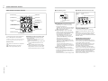
13 12 11 10 9
English
The pin assignment for the unit’s INTERCOM/
TALLY connector (D-sub 25-pin) is as follows.
To switch the DXC-D30WS/D30WSP
aspect ratio
To switch the DXC-D30WS/D30WSP Digital Video
Camera connected to this unit via the CA-TX7/TX7P
Camera Adaptor between 16:9 and 4:3 aspect ratios,
use the following methods.
8
7
6
5
4
3
2
1
25 24 23 22 21 20 19 18 17 16 15 14
Pin assignment of the INTERCOM/TALLY
connector
No.
1
Signal name
Specifications
GREEN TALLY (Y) IN ON: 24V DC/TTL(H)/Short
14
GREEN TALLY (X) IN OFF: 0V DC/TTL(L)/Open
2
RED TALLY (Y) IN
15
RED TALLY (X) IN
OFF: 0V DC/TTL(L)/Open
3
GND
Ground for intercom remote
16
CAM MIC OFF IN
L: Camera intercom off
4
CH2 INT IN
L: Channel-2 interrupt on
17
CH1 INT IN
L: Channel-1 interrupt on
5
4W CH2 (R) (G) OUT
4-wire channel-2 system receive,
18
4W CH2 (R) (Y) OUT
0 dBu balanced
6
4W CH2 (R) (X) OUT
19
4W CH2 (T) (G) IN
7
4W CH2 (T) (Y) IN
ON: 24V DC/TTL(H)/Short
signal
When using the RCP-TX7 Remote Control
Panel
Switch the aspect ratio using advanced setting page
9/11 of the RCP-TX7’s OTHERS menu.
When using the COU-TX7 Camera Operation
Unit
Switch the aspect ratio using the DXC-D30WS/
D30WSP’s advanced menu.
Wide-aspect ID signals
When using the DXC-D30WS/D30WSP connected
to this unit via the CA-TX7/TX7P with the 16:9
aspect ratio, wide-aspect ID signals1) are added to the
video signals2) output from this unit.
It is possible to change the internal board settings of
this unit so that the ID signals are not added to the
video signals.
For more information about this, consult your Sony
service representative.
20
4W CH2 (T) (X) IN
8
2W CH2 (G) IN/OUT
21
2W CH2 (X) IN/OUT
3-864-243-01(1)
2-wire channel-2 system,
0 dBu
Recommended termination
impedance: 600 ohms
9
4W CH1 (R) (G) OUT
4-wire channel-1 system receive,
22
4W CH1 (R) (Y) OUT
0 dBu balanced
10
4W CH1 (R) (X) OUT
23
4W CH1 (T) (G) IN
11
4W CH1 (T) (Y) IN
4-wire channel-1 system talk,
0 dBu balanced
24
4W CH1 (T) (X) IN
12
2W CH1 (G) IN/OUT
2-wire channel-1 system,
25
2W CH1 (X) IN/OUT
0 dBu
Recommended termination
impedance: 600 ohms
13
CHASSIS GND
Chassis ground
0 dBu=0.775 Vrms
1) Complying with EIAJ CPR-1204 (CCU-TX7) or ETS
WSS (CCU-TX7P).
2) • Composite video signals 1 and 2 (output from the
VBS1 and VBS2 connectors)
• Video signal for video monitors (output from the PIX
connector)
• Video signal for waveform monitors (output from the
WF connector)
• Component video Y signal (output from the Y
connector)
• Y signal of Y and C signal output (output from the Y
connector)
4-wire channel-2 system talk,
0 dBu balanced
CCU-TX7 (E)/V1
SDI Output Board
Operating Instructions
DXBK-701
1998 by Sony Corporation
Page 11
GB
1-2. DXBK-701
CCU-TX7 (E)/V1
3-866-203-01(1)
1-13
1-14
English
For the customers in the USA
This equipment has been tested and found to comply
with the limits for a Class A digital device, pursuant to
Part 15 of the FCC Rules. These limits are designed to
provide reasonable protection against harmful
interference when the equipment is operated in a
commercial environment. This equipment generates,
uses, and can radiate radio frequency energy and, if not
installed and used in accordance with the instruction
manual, may cause harmful interference to radio
communications. Operation of this equipment in a
residential area is likely to cause harmful interference in
which case the user will be required to correct the
interference at his own expense.
You are cautioned that any changes or modifications not
expressly approved in this manual could void your
authority to operate this equipment.
The shielded interface cable recommended in this
manual must be used with this equipment in order to
comply with the limits for a digital device pursuant to
Subpart B of Part 15 of FCC Rules.
This device complies with Part 15 of the FCC Rules.
Operation is subject to the following two conditions: (1)
This device may not cause harmful interference, and (2)
this device must accept any interference received,
including interference that may cause undesired
operation.
For the customers in Canada
This Class A digital apparatus complies with Canadian
ICES-003.
CCU-TX7 (E)/V1
11
CCU-TX7 (E)/V1
Location and Function of Parts
For the customers in Europe
This product with the CE marking complies with the EMC
Directive (89/336/EEC) issued by the Commission of the
European Community.
Compliance with this directive implies conformity to the
following European standards:
• EN55103-1: Electromagnetic Interference (Emission)
• EN55103-2: Electromagnetic Susceptibility (Immunity)
This product is intended for use in the following
Electromagnetic Environment (s):
E1 (residential), E2 (commercial and light industrial), E3
(urban outdoors) and E4 (controlled EMC environment
ex. TV studio)
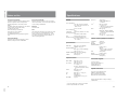
Table of Contents
SDI-44
1 ALARM indicator
ALARM
2 SDI output connectors
3 AUTO LEVEL indicator
AUTO LEVEL
(BARS)
4 AUTO LEVEL switch
SDI POWER
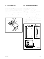
Overview ......................................................................... 12
Location and Function of Parts .................................... 13
Fitting and Adjustment ................................................. 14
Auto Level Adjustment .................................................17
Specifications ................................................................ 18
Overview
The DXBK-701 SDI Output Board is an option board for the
Sony CCU-TX7/TX7P Camera Control Unit. When this board
is fitted in a CCU-TX7/TX7P, it provides an SDI digital signal
output.
Note
This board can be fitted to a CCU-TX7 with serial number
11001 or greater or a CCU-TX7P with serial number 41001 or
greater. 1)
When this board is fitted, the heat generated can cause burns.
Be sure to have the board fitted by your Sony dealer.
..........................................................................................................................
1-15
12
1) Fitting the board to a CCU-TX7 with serial number 11000 or below or a
CCU-TX7P with serial number 41000 or below requires a separate
modification to the CCU-TX7/TX7P. Consult your Sony dealer about
this.
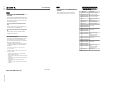
ON
OFF
1 ALARM indicator
This lights red when the SDI signal is
not being output.
2 SDI output connectors
Connect the two cables from the
CCU.
3 AUTO LEVEL indicator
This lights green when the automatic
video level adjustment is carried out
correctly.
5 SDI POWER switch
4 AUTO LEVEL switch
With the output set to color bars, press
this switch to carry out automatic
video level adjustment.
5 SDI POWER switch
Set this to ON to use the SDI output.
When not using the SDI output, set to
OFF to conserve power.
13
1-16
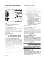
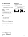
Fitting and Adjustment
Power off the CCU-TX7/TX7P before fitting the board.
1
3 Insert the board partly into the slot.
Check that the switches on the DXBK-701 board (SDI-44)
are set as follows.
FREE LOCK: LOCK
ADJ OPE: OPE
AUDIO MODE: normally 2CH; 4CH if the connected
device does not support 2CH mode. (No audio output is
provided on channels 3 and 4.)
FREE LOCK
FREE LOCK
ADJ OPE
ADJ OPE
4ch 2ch
2
AUDIO MODE
4
Remove the two cables temporarily fixed to the CCU-TX7/
TX7P power supply unit from the clamp, and connect to
the two SDI output connectors on the board. It does not
matter which cable is connected to which connector.
SDI output connectors
Loosen the two screws at the right end of the front panel of
the CCU-TX7/TX7P, and open the front panel. Remove
the board retainer (two screws).
Clamp
Cables
(Continued)
CCU-TX7 (E)/V1
Board retainer
14
15
CCU-TX7 (E)/V1
Fitting and Adjustment
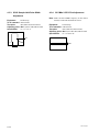
5
Push the board fully in, and refasten the board retainer,
using the two screws removed in step 2.
Auto Level Adjustment
The auto level adjustment is necessary to ensure that the video
levels are appropriate. Carry out auto level adjustment in step 6
(page 16) of the procedure under “Fitting and Adjustment”.
1
Power on the CCU-TX7/TX7P, CA-TX7/TX7P, and
camera.
2
On the RCP-TX7 or COU-TX7/TX7P select “BARS”.
Color bars appear in the monitor or viewfinder.
3
Board retainer
6
Set the SDI POWER switch to ON. (See page 13.)
7
Power on the CCU-TX7/TX7P, and carry out auto level
adjustment. (See page 17.)
8
Close the front panel of the CCU-TX7/TX7P, and fasten
the screws.
With a pen or other sharp implement, press the AUTO
LEVEL switch.
After a few seconds, when the AUTO LEVEL indicator
lights in green the auto level adjustment is completed.
Notes
• If the indicator lights in red, check the switch setting on the
board. (See step 1 on page 14.) If the indicator flashes, check
that color bars are being displayed.
• The adjustment values are stored on this board, so
readjustment is not normally required.
However, if the CCU-TX7/TX7P is not used for a long time
(several months), or if the board is installed in a different
CCU-TX7/TX7P, the auto level adjustment must be made
again.
For details of the operating procedures for other devices, refer to the
operating instructions supplied with each device.
1-17
16
17
1-18
Specifications
Power consumption
Operating temperature
Mass
Dimensions
Output signal
CCU-TX7 (E)/V1
18
4.5 W
5°C to 40°C (41°F to 104°F)
330 g (11 oz)
17 × 148 × 277 mm (11/16 × 5 7/8 × 11
inches) (w/h/d, excluding
projections)
SDI output connectors
SDI format (270 Mbps)
SMPTE 259M (CCU-TX7)/
CCIR 656-III (CCU-TX7P)
SECTION 2
INSTALLATION
2-1. CONNECTORS AND CABLES
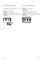
. MIC OUTPUT CH1/CH2 (XLR 3P, MALE)
2-1-1. Connector Input/Output Signals
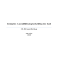
The connector input/output signals are described below.
1. Rear panel
(EXTERNAL VIEW)
BNC connector: 75 Z
(0 dBu = 0.775 Vrms)
[Input signals]
.
.
.
.
GENLOCK (BNC)
RETURN VIDEO 1/2 (BNC)
PROMPT VIDEO (BNC)
SPARE (BNC) *1
: VBS/BS, 1.0 V p-p
: VBS, 1.0 V p-p
: VBS, 1.0 V p-p
: RM Video Input
VBS, 1.0 V p-p
No.
Signal
Specifications
1
MIC OUT (G)
0 dBu/ _20 dBu
2
MIC OUT (Y)
(Selectable with MIC switch on AA-90
3
MIC OUT (X)
board)
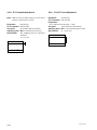
. WF MODE (4P, FEMALE)
[Output signals]
.
.
.
.
.
R (BNC) *2
G (BNC) *2
B (BNC) *2
Y (BNC) *2
R-Y (BNC) *2
. B-Y (BNC) *2
. C (BNC) *2
(for CCU-TX7)
.
.
.
.
.
: 700 mV p-p
: 700 mV p-p
: 700 mV p-p
: 1.0 V p-p
: 700 mV p-p
: 525 mV p-p
: 700 mV p-p
: 525 mV p-p
: 286 mV p-p
4
1
3
2
(EXTERNAL VIEW)
(for CCU-TX7)
(for CCU-TX7P)
(for CCU-TX7)
(for CCU-TX7P)
(burst)
: 300 mV p-p (for CCU-TX7P)
PIX (BNC)
: 1.0 V p-p
VBS 1/2 (BNC) : 140 IRE
SYNC (BNC) : VBS, 0.3 V p-p, negative
WF (BNC)
: 700 mV p-p
(Encoded output : 1.0 V p-p)
SDI OUT (BNC) : 800 mV p-p
(0 dBu = 0.775 Vrms)
No.
Signal
Specifications
1
SEQ CONT OUT (G)
OPEN COLLECTOR
2
SEQ CONT OUT (X)
3
STAIR CASE OUT (X)
∗1)
4
STAIR CASE OUT (G)
GND for STAIR CASE
∗1) Stair Case signal
10 ±2 V
R
G
B
DC0 ±2 V
*1 : Located on the OUTPUT connector block of the rear
panel for the unit with the following Serial Nos.
Serial No. 13016 and higher (UC)
Serial No. 42930 and higher (CE)
*2 : R/G/B, Y/R-Y/B-Y, Y/C selection (Selectable with
S800, S801 on the ES-20 board)
[Input/Output signals]
. TRIAX : King type (for CCU-TX7)
Fischer type (for CCU-TX7P)
. COAX (BNC)
CCU-TX7 (E)/V1
2-1
. INTERCOM/TALLY (D-Sub 25P, FEMALE)
13
. RS-232C CH1/CH2 (D-Sub 25P, FEMALE)
1
25
13
14
1
25
(EXTERNAL VIEW)
14
(EXTERNAL VIEW)
(0 dBu = 0.775 Vrms)
No.
Signal
1
Specifications
(0 dBu = 0.775 Vrms)
No.
Signal
Specifications
GREEN TALLY (Y) IN ON : 24 V DC/TTL (H)/SHORT
1
CHASSHIS GND
This is based on RS-232C
14
GREEN TALLY (X) IN OFF : 0 V DC/TTL (L)/OPEN
2
TXDATA
specification.
2
RED TALLY (Y) IN
ON : 24 V DC/TTL (H)/SHORT
3
RXDATA
38,400 bps or 9600 bps Switchable
15
RED TALLY (X) IN
OFF : 0 V DC/TTL (L)/OPEN
3
GND
GND for INTERCOM REMOTE
4
RTS
16
CAM MIC OFF IN
L: CAM INCOM MIC OFF
5
CTS
DSR
by the internal switch on the
4
CH2 INT IN
L: CH2 INTERRUPT ON
6
17
CH1 INT IN
L: CH1 INTERRUPT ON
7
GND
5
4W CH2 (R) (G) OUT
4W CH2 SYSTEM RECEIVE
20
DTR
18
4W CH2 (R) (Y) OUT
0 dBu BALANCED
6
4W CH2 (R) (X) OUT
19
4W CH2 (T) (G) IN
4W CH2 SYSTEM TALK
7
4W CH2 (T) (Y) IN
0 dBu BALANCED
20
4W CH2 (T) (X) IN
8
2W CH2 (G) IN/OUT
2W CH2 SYSTEM 0 dBu
21
2W CH2 (X) IN/OUT
Recommended Term. imp.= 600 Z
9
4W CH1 (R) (G) OUT
4W CH1 SYSTEM RECEIVE
22
4W CH1 (R) (Y) OUT
0 dBu BALANCED
10
4W CH1 (R) (X) OUT
23
4W CH1 (T) (G) IN
4W CH1 SYSTEM TALK
11
4W CH1 (T) (Y) IN
0 dBu BALANCED
24
4W CH1 (T) (X) IN
12
2W CH1 (G) IN/OUT
2W CH1 SYSTEM 0 dBu
25
2W CH1 (X) IN/OUT
Recommended Term. imp.= 600 Z
13
CHASIS GND
CT-181 board of CCU.
. REMOTE (10P FEMALE)
8
1
10
9
5
4
7
2
6
3
(EXTERNAL VIEW)
No.
Signal
Specification
1
(SPARE)
—
2
RM VIDEO OUT (X) *
3
RM VIDEO OUT (G)
*
4
S. DATA (RCP → CCU)
5
S. DATA GND
VBS, 1.0 V p-p
RX DATA equivalent
communication rate that is
based on RS-232C
specification is 38,400 bps.
6
S. DATA GND
TX DATA equivalent
7
S. DATA (CCU → RCP)
communication rate that is
based on RS-232C
specification is 38,400 bps.
8
(SPARE)
—
9
POWER +12.5 V DC GND
GND for +12.5 Vdc
10
POWER +12.5 V DC OUT
10.6 V to 17.0 Vdc
* : The units with the following Serial Nos. output the RM video out signal.
Serial No. 13016 and higher (UC)
Serial No. 42930 and higher (CE)
2-2
CCU-TX7 (E)/V1
2. Front panel
. PGM IN (XLR 3P, FEMALE)
. INTERCOM (XLR 5P, FEMALE)
(EXTERNAL VIEW)
(EXTERNAL VIEW)
No.
Signal
Specifications
1
PGM IN (G)
0 dBu/ _20 dBu
2
PGM IN (X)
(Selectable with PGM switch on AA-90
3
PGM IN (Y)
(0 dBu = 0.775 Vrms)
board)
. RTS IN/OUT (XLR 3P, FEMALE ↔ MALE)
FEMALE
MALE
No.
Signal
Specifications
1
INCOM (T) (G) IN
_60 dBu (DYNAMIC MIC)
2
INCOM (T) (X) IN
_20 dBu (CARBON MIC)
3
NCOM (R) (G) OUT
GND for HEADPHONE
4
INCOM (R) (X) OUT
_0 dBu (Max. 18 dBu)
5
PGM (X) OUT
Loop-through
(EXTERNAL VIEW)
(EXTERNAL VIEW)
No.
Signal
Specifications
1
GND
0 dBu/ _10 dBu (Clear-Com)
2
RTS CH2 (X) IN/OUT
Current drive
3
RTS CH1 (X) IN/OUT
Recomended Term. lmp.= 200 Z
. DC IN (XLR 4P, MALE)
(EXTERNAL VIEW)
No.
Signal
Specifications
1
GND
GND for DC (+)
2
(SPARE)
—
3
(SPARE)
—
4
DC (+) IN
DC 10.5 V to 17 V
CCU-TX7 (E)/V1
2-3
2-1-2. Connection Connector
2-1-3. Wiring Diagram for Cable
Use the connectors below or the equivalent at its tip when
cables are connected to each connector on the connector
panel during installation and servicing.
. CCA-7 cable
Connector name
Blue
White
Connected connector/cable
Orange
GENLOCK VIDEO 1, 2
RETURN VIDEO
PROMPT VIDEO
R/R-Y/C 1, 2
G/Y/Y 1
B/B-Y 1, 2
WF
PIX
VBS 1/2
SYNC
COAX
(BNC type)
1-560-069-11 plug,
BNC, or B-B cable assembly
(1.5 m in cable length, optional)
MIC CH1/CH2
RTS
(3P, MALE)
1-508-083-00 XLR, 3-pin
FEMALE or
CANNON XLR-3-11C
or the equivalent
PGM IN
RTS
1-508-084-00 XLR, 3-pin
MALE or
CANNON XLR-3-12C
or the equivalent
Black
Green
8
7
1
8
2
9 10
6
7
2
6
3
5
1
9 10
4
3
5
4
White
Brown
INTERCOM/TALLY
RS-232C CH1/CH2
(25P, FEMALE)
D-Sub, 25-pin male,
JAE DA-25PF-N or the equivalent
WF MODE
(4P, FEMALE)
1-560-343-11 plug, 4-pin male
REMOTE
(10P, FEMALE)
1-766-848-11 plug, 10-pin male, or
CCA cable assembly
CCA-7-5 (supplied with RCP-TX7)
(50 m max.)
INTERCOM
(5P, FEMALE)
1-508-370-11 XLR, 5-pin male,
or CANNON XLR-5-12-C or the
equivalent
White
Red
Yellow
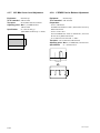
2-2. MAKING OF WF MODE
CONNECTOR
. When connecting plug to wave form monitor, make the
plug as follow.
PLUG (4P) (Sony part No. 1-560-343-11)
4
1
3
2
To wave form monitor
(REMOTE)
(EXTERNAL VIEW)
GROUND
4
1
3
2
(WIRING SIDE)
STAIR CASE
SEQ CONT
2-4
CCU-TX7 (E)/V1
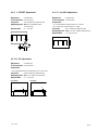
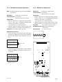
2-3. COAX CONNECTOR
2-4. OPERATING ENVIRONMENT
The COAX connector (BNC type) can be used for connection
between the CCU and the CA with a BNC cable instead of a
triaxial cable. In this case, supply the power source from
outside to the CA side.
And for the CA side, it is needed to modify the TRIAX
harness to the COAX harness.
For the CCU, the following modification is required.
Disconnect the RF cable from the CN3 on the IO-141 board
and reconnect it to the CN4.
Operating temperature
Storage temperature
Humidity
Supply voltage
Power consumption
RF cable
IO-140 board
: +5 dC to +40 dC
: _20 dC to +55 dC
: Noncondcnsing
: 100 V to 240 V ± 10% (50/60 Hz)
: 95 W (maximum)
1. Do not put the unit in a place subject to high temperature
or in a location near hear sources.
2. Do not put the unit in a place subject to excessive
electrical and magnetic fields.
3. Put the unit in a dry and well-ventilated place.
4. Do not put the unit in a place subject to excessive dust
and mechanical shock.
5. Do not put the unit in a place subject to direct sunlight
and light.
CN3
169
164
300
CN4
8
200
217.5
9.5
(Unit: mm)
CCU-TX7 (E)/V1
2-5
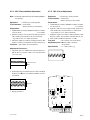
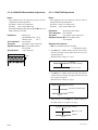
2-5. MOUNTING ON 19-INCH RACK
Two CCU-550s can be mounted on a 19-inch EIA standard
rack in parallel by using rack mount adaptor RMM-TXC7
(optional).
Mounting
1. Tighten the four rack mount screws.
RMM-TXC7
B5 screws
(60 mm or more long)
2. Mount the CCU-TX7/TX7P on the rack mount adaptor
as shown in the figure below and tighten the four fixing
screws (supplied for RMM-TXC7).
Screws
Screws
2-6
CCU-TX7 (E)/V1
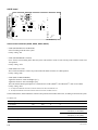
2-6. SWITCH FUNCTIONS ON BOARD
CT-181 board
E1001
TP2006
CT-181
RET FREQ
CV1
S2011
R TALLY
R TALLY
CONTACT
TP1000
DC24V
S2013
TTL R TALLY
CONTACT
CONTACT
POWER
G TALLY
POWER
DC24V
DC24V
TTL
S1001
PANEL
SELECT
PANEL
REMOTE
LOCAL
CONTROL MODE
NORMAL
SLAVE
RV22
PROMPT FREQ
S2012
RV23
S2014
PROMPT TUNE
PROMPT LEVEL
LV3
S2002
E13
PROMPT
MIC 2 GAIN
S1004
S1000
MIN
MAX
CH-2
RF AGC DLY
SW1000
SW1001
CH-1
LOCAL REMOTE
MIN
MAX
NORM
E12
G TALLY
TTL
MIC 1 GAIN
MIC GAIN
NORM
E1000
NORM
CONT MODE
SLAVE
S1002
RX
RS232C-2
IF BOARD
TX
TP22
TP23
G TALLY
TP1002
POWER
DC24V
TTL
LV2
POWER
TP21
CONTACT
CN7
CN8
PROMPT RF RX
TP1001
TP2001
E16
TP2003 TP2002 TP2004
TP2005
CT-181 Board (A SIDE)
. S1000
This switch is for the adjustment in the factory.
Factory setting : All OFF
. S1001 (PANEL REMOTE/LOCAL)
When the RCP or COU is connected, the connected one is
selected in spite of PANEL setting.
Also, when both RCP and COU are connected, RCP or
COU is selected according to the PANEL (REMOTE/
LOCAL) setting.
Factory setting : REMOTE
Note :
RCP : Remote Control Panel
RCP-TX7
COU : Camera Operation Unit COU-TX7
. S1002 (CONTROL MODE NORMAL/SLAVE)
The RCP is only connected or both RCP and COU are
connected and then the S1001 switch is set to REMOTE
side. In this case, the RCP is valid, and this S1002 switch
is invalid. The COU is only connected or both RCP and
COU one connected, and then the S1001 switch is set to
LOCAL side. In this case, the COU is valid, and this S1002
switch is used as follows ;
NORMAL : COU can be used
SLAVE : The operation of CCU can be used.
COU can not be used.
Factory setting : NORMAL
. S1004
This switch is used to change the RS-232C and IF BOARD.
Factory setting : RS-232C side
CCU-TX7 (E)/V1
. S2002 (PROMPT SELECT TX/RX)
TX : When selecting the TX mode, the CCU modulates
the VBS signal input to the PROMPT VIDEO IN
connector on the CCU-TX7/TX7P, and modulated
signal is sent to the CA-TX7/TX7P.
RX : When selecting the RX mode, the CA modulates
the VBS signal input to the PROMPT VIDEO IN
connector on the CA-TX7/TX7P, and modulated
signal is sent to the CCU-TX7/TX7P.
Note : When using this switch, change as follows.
. In case of using the TX mode (TX side) ;
1) Disconnect CN8 and connect CN3 and CN7
on the CT-181 board.
2) Set S1 and S6 switches to "PROMPTER" side
on the YD-25 board of CA-TX7/TX7P.
. In case of using the RX mode (RX side) ;
1) Disconnect CN7 and connect CN3 and CN8
on the CT-181 board.
2) Set S1 and S6 switches to "AUX" side on the
YD-25 board of CA-TX7/TX7P.
Factory setting : TX
. S2011 (R TALLY POWER/CONTACT)
. S2013 (R TALLY DC24 V/TTL)
These switches are set according to the signal standard of
the R TALLY signal input to the INTERCOM/TALLY/
PGM connnector on the CCU rear panel. For the relation
between the signal and switch setting, refer to the table below.
Factory setting : (S2011) POWER
(S2013) DC 24 V
. S2012 (G TALLY POWER/CONTACT)
. S2014 (G TALLY DC 24 V/TTL)
These switches are set according to the signal standard of
the G TALLY signal input to the INTERCOM/TALLY/
PGM connector on the CCU rear panel. For the relation
between the signal and switch setting, refer to the table below.
Factory setting : (S2012) POWER
(S2014) DC 24 V
Switch
Signal input method
Contact
+24 V) TTL (+
+5 V)
Power (+
S2011, S2012
Contact
Power
Power
S2013, S2014
DC 24 V or TTL
DC24 V
TTL
. SW1000 (MIC GAIN … CH1)
. SW1001 (MIC GAIN … CH2)
Use these screws to adjust the microphone amplifier gain
for the camera adaptor. The standard level (NORM) is 0
dB, and the gain setting can be adjusted to any of 16 levels
from _12 dB (MIX) to +12 dB.
2-7
4W
RTS
CLEAR
COM
TP8
RV41
RV81
TP1
1CH
INCOM MODE
S2003
E11
2CH
3.6M
RTS CH RTS 200
REV
OHM
LV41
4.3M
REV STD OFF ON
TP11
LV61
TP46
TP3005
TP3002
TP3004
RV2000
SIDE TONE
TP3003
TP3001
RTS
H CONT
TP43
5.6M TUNE
INCOM
DEV
)
LV101
E1
PGM
DEV
(
TP14
2.5M CCU DATA
LV1 3.0M
S2005 S2002
2W
RTS/CLEAR-COM INCOM SELECT
INTER COM
MIC 1
LEV
RV201
TP10
TP13
MIC 2
LEV
LV21
LEVEL IND
CLEAR
COM
TP7
TP2
OFF
TONE TUNE
E10
S2007 S2006
CH-2
T401
E2 TP6
TP3
CH-1
TP15
T301
TP5
S2004
MIC TEST
TP9
TP12
RV101
S301
—20dB
MIC-2-LEV
—20dB
MIC 2 LEVEL
T201
RV401
PGM IN
0dB
MIC-1-LEV
S201
MIC 1 LEVEL
0dB
TP44
MIC TEST
—20dB
S2081
0dB
INCOM
LEV
E12
AA-90
PGM IN
RV301
AA-90 board
E3001
AA-90 Board (A SIDE)
Intercom select switches (S2002, S2003, S2005, S2007)
. S2002 (INCOM SELECT 2W/RTS/4W)
Select according to the intercom system.
Factory setting : 4W
. S2003 (INCOM MODE 1CH/2CH)
Set to 1CH or 2CH according to the intercom system. The interface circuit of CH1 side only works with the switch set to
1CH position.
Factory setting : 2CH
. S2005 (RTS/Clear-Com)
This switch selects RTS or Clear-Com position when the S2002 switch is set to RTS position.
Factory setting : RTS
. S2007 (RTS CH REV STD/REV)
Applicable Serial No. 10801 and Higher [UC]
Applicable Serial No. 40136 and Higher [CE]
This switch allows RTS input/output to be switched between CH1 (PROD*1) and CH2 (ENG*2) when it sets to REV.
Factory setting : STD
*1 : Corresponds to PROD side of the intercom selector switch for CCU-550, CCU-550P and so on.
*2 : Corresponds to ENG side of the intercom selector switch for CCU-550, CCU-550P and so on.
Set the S2002, S2003, S2005 and S2007 switches to the positions shown in the table below, according to the intercom system.
X : Don’t care
Intercom system to be connected
S2002
S2003
S2005
S2007
4-wire system
4W
2CH
X
X
2-wire system
2W
2CH
X
X
RTS TW system (2CH)
RTS
2CH
RTS
REV
CH1 (CCU) 5 CH1 (RTS)
CH2 (CCU) 5 CH2 (RTS)
STD
CH1 (CCU) 5 CH2 (RTS)
CH2 (CCU) 5 CH1 (RTS)
Clear-Com 1 ch system
1CH
Clear-Com
STD
Clear-Com TW system
2CH
Clear-Com
REV
2-8
Remarks
CCU-TX7 (E)/V1
. S201 (MIC 1 LEVEL)
This switch sets the audio signal level of the MIC OUTPUT
CH-1 connector on the CCU rear panel to 0 dBu or _20 dBu.
Factory setting : 0 dBu
. S301 (MIC 2 LEVEL)
This switch sets the audio signal level of the MIC OUTPUT
CH-2 connector on the CCU rear panel to 0 dBu or _20 dBu.
Factory setting : 0 dBu
. S2004 (MIC TEST)
This switch is for mixing the MIC (1 or 2) audio from the
CA-TX7/TX7P with the program audio (PGM) and for
monitoring the audio.
CH-1 : MIC 1 audio mixes to the program audio.
CH-2 : MIC 2 audio mixes to the program audio.
OFF : MIC 1 audio and MIC 2 audio do not mix to the
program audio.
Factory setting : OFF
. S2006 (RTS 200 Z ON/OFF)
This switch sets to ON or OFF position for 200 Z
termination in the RTS system. Usually, this switch sets to
OFF position because the RTS system has 200 Z
termination.
Factory setting : OFF
. S2081 (PGM IN)
This switch sets the PGM (program audio) level to 0 dBu or
_20 dBu.
Factory setting : 0 dBu
CCU-TX7 (E)/V1
2-9
YD-26 board
TP26
E5
TP10
SAMPL GATE
RV3
SAMPL S/H
Y OFFSET ADJ
TP5
TP8
TP4 TP7
Y RF TUNE
ON
OFF
S3
LV1
RV6
VCO DC SET
RV2
BLACK S/H
TP3
TP6
RV5
TP9
SYNC S/H
TP17
S4
C 2'nd AGC
RV12
RV7
Y 2'nd AGC
OFF
ON
TP14
Y LEVEL
RV9
E6
TP12
B-Y LEVEL
E8
R-Y CARR BAL
B-Y CARR BAL
TP19
RV16
TP18
RV11
RV17
R-Y LEVEL
E7
TP13
TP11
RV8
E9
TP18
TP2
YD-26
Y CARR BAL
RV4
E2
Y CAR LEVEL
RV1
Y AGC CONT
RV24
E1
TP15
RV10
RV18
C AGC CONT
90° SET
RV13
RV14
RV15
OFFSET ADJ
PLL SET
C CAR LEV
E16
TP1
E4
S2
E3
CABLE LENGTH
TP21
TP20
AUTO
MODE
MAN
S1
YD-26 Board (A SIDE)
. S1 (MODE AUTO/MANU)
The length of a triax cable connecting the camera head
and CCU is automatically detected and set when this switch
is set to AUTO. The triax cable length can be manually set
using S2 (CABLE LENGTH SELECT) when this switch
is set to MANU (MANUAL).
Factory setting : AUTO
. S3 (Y-ch 2nd AGC ON/OFF)
. S4 (CHROMA-ch 2nd AGC ON/OFF)
These switches are used for RF AGC adjustment. Usually,
set these switches to ON.
. S2 (CABLE LENGTH SELECT)
This switch is valid when S1 is set to MANU. This switch
is set to the number corresponding to the cable length.
Factory setting : 0 (100 m)
Switch setting
Cable length (center value)
0
100 m
1
300 m
2
500 m
3
700 m
4
NOT IN USED
2-10
CCU-TX7 (E)/V1
RV804
G MAT BAL2
B WHT BAL
R WHT BAL
RV506
RV505
RV500
TP501
TP506
RV507
G MAT BAL1
G LEVEL
TP502
TP507
RV508
R MAT BAL
RV511
R DC BAL
RV510 R LEVEL
RV509
TP503
B MAT BAL
RV501
RV513 B LEVEL
RV809
(U)LEV
RV808
Q(U)CAL
TP7
TP5
TP4
TP2
TP3
POSITION
R-Y GAIN ADJ
RV502
RV1000
RV512
RV514
B DC BAL
R-Y BLK BAL
RV504
B-Y GAIN ADJ
RV503
E16
S4
S801
OUTPUT 2
SELECT
Y/C
S1000
S1
Y/R-Y/B-Y
RV812
B-Y LEVEL
RV1001
R/G/B
E3
SEQ ON
E1
S2
Y/C
OUT PUT 2
Y CLP LEVEL
Y/R-Y/B-Y
SC-H PHASE
TP505
RV515
S800
R/G/B
OUTPUT 1
SELECT
RV5
OUT PUT 1
BURST
PHASE
TP1
SC FREQUENCY
RV807
RV4
RV801
RV810
Y LEVEL(COMP)
SYNC LEVEL(COMP)
RV811
S3
180°
SC 0/180
0
Y SETUP LEVEL
(NTSC ONLY)
RV805
RV6 SC PHASE
SC
RV800
BURST
LEVEL
SYNC PHASE
R-Y LEVEL
RV7 H PHASE
RV806
RV2
I(V)CAL
H
RV1
PHASE
CAM H PHASE
RV3
ES-20
CHROMA LEVEL
RV803 RV802
TP17 TP15
SYNC WIDTH
RV813
Y LEVEL (VBS)
SYNC LEVEL (VBS)
VBS LEVEL
ES-20 board
LEVEL
B-Y BLK BAL
ES-20 Board (A SIDE)
. S1 (V BLKG 19H/20H/21H) … NTSC only
This switch sets the V blanking width to 19H, 20H, or 21H.
Set this switch according to the application.
Factory setting : 20H
. S2 (H BLKG)
This switch is used for H blanking width adjustment.
During factory setting, this switch is set so that the H
blanking with is 10.9 ± 0.2 usec. Set this switch according
to the application.
. S3 (SC 0d/180d)
This switch is used for the adjustment of subcarrier phase
between the input video signal (GEN LOCK IN) and output
video signal (VBS OUT).
The SC phase can be selected to 0d or 180d.
Factory setting : 0d
. S801 (OUTPUT 2 SELECT)
. R/G/B
. Y/R-Y/B-Y
. Y/C
This switch selects the signals of the G/R/B, Y/R-Y/B-Y,
and Y/C to output the OUTPUT 2 connectors on the CCU
rear panel.
Factory setting : R-Y/Y/B-Y
. S1000 (SEQ ON +/_)
Set this switch to + or _ position according to the waveform
monitor to be used.
+ : NPN open collector output
_ : PNP open collector output
Factory setting : +
. S800 (OUTPUT 1 SELECT)
. R/G/B
. Y/R-Y/B-Y
. Y/C
This switch selects the signals of the G/R/B, Y/R-Y/B-Y,
and Y/C to output the OUTPUT 1 connectors on the CCU
rear panel.
Factory setting : R-Y/Y/B-Y
CCU-TX7 (E)/V1
2-11
DU-33 board
AU-234 board
[For the Serial No. 10601 and Higher (UC)]
[For the Serial No. 40251 and Higher (CE)]
OFF
CN1
ON
CN3
S1
CN4
RV1
S4
DU-33 Board (A SIDE)
CALL
. S1 (WIDE ID ON/OFF)
Set this switch to ON position when the 16:9 compatible
camera is connected and used in the 16:9 mode.
Factory setting : ON
ON
S1
CH1
PRI
VATE
S3
CH2
OFF
ON
S2
RV1
RV2
OFF
S5
DINAMIC
CN1
CARBON
AU-234 Board (A SIDE)
. S5 (DYNAMIC/CARBON)
Set this switch according to the type of the headset
microphone connected to the INTERCOM connector on
the front panel.
DYNAMIC
: Dynamic type microphone
CARBON
: Carbon type microphone
Factory setting : DYNAMIC
2-12
CCU-TX7 (E)/V1
SDI-44 board
TP101 E101
TP805
TP806
TP807
TP810
SDI-44
ALARM
RV1401 RV1400
B-Y DC B-Y LEVEL
TP1400
D201
S701
LOCK FREE
RV1501 RV1500
RV701
R-Y DC R-Y LEVEL
TP1500
TP702
CN2
S601
OPE
TP1201 E201
ADJ
TP1300
TP701
RV1301 RV1300
Y DC Y LEVEL
OFF
D601
AUTO IND
AUTO LEVEL
ON
S201
SDI POWER
AUTO IND
AUTO LEVEL
(BARS)
S602
CN3
E1001
RV904
RV903
TP902
RV901
TP901
RV902
SDI-44 Board (A SIDE)
. S701 (for factory adjustment)
Factory setting: LOCK
. S601 (ADJ/OPE)
This switch is used for returning the level control values of
the R-Y and B-Y video signals to the factory setting.
Set this switch to ADJ position and turn on the power to
the main unit.
Alternatively, set this switch to ADJ position and press the
AUTOLEVEL (BARS) switch.
Usually, set this switch to OPE position.
Factory setting : OPE
. S401 (AUDIO MODE)
Set this switch sets to 4CH position when the units is
connected to an equipment with cannot receive SDI audio
in 2CH mode.
It is impossible to send audio signals to channels 3 and 4
even if this switch is set to 4CH.
Usually, set this switch to 2CH position.
Factory setting : 2CH
CCU-TX7 (E)/V1
2-13
SECTION 3
SERVICE INFORMATION
3-1. BOARD LAYOUT
3-2. DISASSEMBLY/INSTALLATION OF
MAIN PART
IO-140 board
CN-1327 board
MB-693 board
SDI-44 board (DXBK-701)
CN-1351 board
CT-181 board
CN-1325
board
AA-90 board
YD-26 board
ES-20
board
3-2-1. Removal of Cabinet
(1) Removal of Front Panel
1.
Front panel
CN-1328 board
CN-1350 board
SW-892
board
Switching regulator
(COU-TX7)
AU-234 board
Loosen
two coin
screws
2.
+K 3x6
Step shaft
Connector
Connector
AU-234 board
Front panel
CCU-TX7(E)/V1
3-1
3-2-2. Replacement of Switching Regulator
(2) Removal of Cover
[For the Serial No. 10001 through 11000 (UC)]
[For the Serial No. 40001 through 41000 (CE)]
Top cover
B 3x5
1. Remove the top and bottom covers. (Refer to "3-2-1.
Removal of Cabinet".)
2. Remove four screws (K3x6) and disconnect CN1 on the
IO-140 board and CN10, CN19 and CN20 on the MB693 board. Remove the rear panel.
Connector (CN10)
B 3x5
Connector (CN1)
MB-693 board
IO-140 board
B 3x5
K 3x6
Bottom cover
B 3x5
Connector (CN19)
Connector (CN20)
Rearpanel
K 3x6
3. Remove six screws (B4x5) and switching regulator.
B 4x5
B 4x5
B 4x5
Switching regulator
4. When installing a new switching regulator, reverse the
above procedures.
3-2
CCU-TX7(E)/V1
3-2-3. Replacement of Fan
[For the Serial No. 11001 and Higher (UC)]
[For the Serial No. 41001 and Higher (CE)]
1. Remove the top cover. (Refer to “3-2-1. Removal of
Cabinet”.)
2. Remove four screws (K3x6) and disconnect CN1 on the
IO-140 board and CN10, CN19, CN20 and CN28 on the
MB-693A board. Remove the rear panel.
3. Remove four screws (PSW3x20) and remove the fan.
Fan
[For the Serial No. 11001 and Higher (UC)]
[For the Serial No. 41001 and Higher (CE)]
n
. When the fan is out of order, the CAMERA POWER
indicator is blinking.
Turn off the power immediately and replace the fan.
Using the defective fan may reduce the service life of the
equipment extremely.
. Before replacing the fan, be sure to turn off the power
switch and unplug the power cord.
PSW 3x20
1. Perform steps 1 to 3 in Section “3-2-2. Replacement of
Switching Regulator” for the Serial No. 11001 and
higher (UC), Serial No. 41001 and higher to remove the
fan.
2. Install a new fan in the reverse order.
A
Connector (CN10)
Connector (CN1)
IO-140 board
MB-693A board
3-2-4. Removal of COU-TX7
K 3x6
As for installing of COU-TX7, refer to “Installing the Camera
Operation Unit” of service manual SECTION 1.
A
Connector
(CN28)
Connector (CN19)
Rearpanel
K 3x6
Connector (CN20)
4. Remove six screws (B4x5) and switching regulator.
B 4x5
B 4x5
B 4x5
Switching regulator
5. When installing a new switching regulator, reverse the
above procedures.
CCU-TX7(E)/V1
3-3
3-3. CIRCUIT DESCRIPTION
CT-181 board
CT-181 board employs RF system circuit that is consists of
RETURN VIDEO modulation circuit and PROMPT VIDEO
modulation circuit (It becomes AUX VIDEO demodulation
circuit by switching.) and microcomputer system circuit that
controls the system.
Microcomputer system circuit section :
The program is written in the ROM (IC1022) that is inserted
to socket (CNI 1). ROM of built-in microcomputer is not
used. Input and output of control signals between each board
in CCU (included in COU) and each board are performed by
serial data of 16 bit via I/O EXPANDER (IC1028). There are
four communication channels with outside. The SCI-1 and
SCI-2 built-in microcomputer communicate with CA (via
modulation and demodulation circuit ) and RCP (via RS-232C
driver). The external SCI (IC1024 and 1025) communicates
with command link (RS-232C-1 and RS-232C-2 on the rear
panel).
The RF system circuit section :
RETURN VIDEO modulation circuit frequency-modulates
the input signal (VBS) from RETURN VIDEO 1 or 2, and
sends to the CA. Change of RETURN VIDEO 1 or 2 is
switched by RETURN 1 and 2 changing switch on the CA.
The PROMPT VIDEO modulation circuit amplitudemodulates the input signal (VBS) from PROMPT VIDEO on
the rear panel, and sends to the CA. The PROMPT VIDEO
modulation circuit becomes AUX VIDEO demodulation
circuit by switching S2002 and connecting RF coaxial cable to
CN3 and CN8. (It is needed to change on the YD-25 board of
CA.)
Demodulated AUX VIDEO is outputted from PROMPT
VIDEO on the rear panel.
YD-26 board
YD-26 board demodulates Y, R-Y, B-Y, CAM SYNC and
SKIN GATE. This circuit consists of cable length detection
circuit, cable length compensation circuit and these
demodulation circuits. The cable length detection detects
from amplitude of Y modulated wave. In accordance with
this, the cable compensation circuit compensates the
amplitude and phase matching as cable length to modulated
wave of Y or differential signal. After that, they are
respectively demodulated in demodulator circuit.
ES-20 board
This board produces VBS and RGB signal from the Y, R-Y,
and B-Y signals sent from the YD-26 board, switches these
signals, and outputs them as WF and PIX signals. This
board also generates each sync signal and color bars signal.
AU-234 board
This board inputs and outputs an INCOM signal on the front
panel, displays tally signals, and turns on and off the power
of camera.
IO-140 board
This board mixes the RF signal between CA and CCU with
the power of the camera.
SDI-44 board (DXBK-701)
This board converts the analog video/audio signals into
digital signals and outputs them as SDI signals.
Video signal processing :
Y, R-Y and B-Y signals sent from the ES-20 board are
converted from analog to digital and subject to the double
over-sampling process on the digital filter IC308.
AA-90 board
This board demodulates the RF signal of MIC1, MIC2,
INCOM, CAM DATA and TONE sent from the CA,
modulates a PGM signal, the INCOM signal and control data
send to the CA. And also, this board switches the INCOM
line, and switches the input /output of each audio signals.
Audio signal processing :
MIC1 and MIC2 signals sent from the AA-90 board are
converted from analog to digital and subject to 64 times
over-sampling process on IC904 and then subject to timebase compression on IC404.
These digital video signals and the time-base compressed
digital audio signals are mixed on IC413. After that, the
parallel data is converted to serial data on IC702 and output
from this board.
3-4
CCU-TX7(E)/V1
3-4. EXTENSION OF DXBK-701
(SDI-44 BOARD)
1. Disconnect two coaxial cables from the SDI-44 board.
2. Extend the SDI-44 board with the EX-564 board.
To confirm the SDI signal output with the SDI44 board extended:
Preparation:
1 Coaxial connector converter : Sony part No. 1-750-881-11
2 Coaxial cable assembly :
Sony part No. 1-765-112-12
3 BNC cable :
BELDEN 8281 cable or
equivalent
Connect 1 Coaxial cable assembly, 2 Coaxial connector
converter, and 3 BNC cable as shown below.
Coaxial cables
SDI-44 board
EX-564 board
2 Coaxial cable
assembly
1 Coaxial
connector
converter
3 BNC cable
Equipment,
Monitor
CCU-TX7(E)/V1
3-5
SECTION 4
ADJUSTMENT
4-1. Preparation
4-1-3. Notes on Adjustment
4-1-1. Equipment Required
CAUTION
. Oscilloscope (more than 300 MHz)
Tektronix 2465 or equivalent
. Waveform monitor/Vectorscope
Tektronix 1765 or equivalent
. Color monitor Sony PVM-1354Q or equivalent (For NTSC)
Sony PVM-1454QM or equivalent (For PAL)
. Video signal generator
Tektronix 1410 or equivalent (For NTSC)
Tektronix 1411 or equivalent (For PAL)
(Color Bar signal, 10 STEP signal,
SWEEP signal)
. Video camera Sony DXC-637 or DXC-D30 (NTSC)
Sony DXC-637P or DXC-D30P (PAL)
. Remote control Unit
Sony RCP-TX7
(or COU-TX7 : Camera Operation Unit)
. Digital voltmeter
. Frequency counter
. Audio generator
. Spectrum analyzer
. TRIAX Cable
4-1-2. Fixture
Extension board
EX-564 (For CCU-TX7/TX7P)
Extension board
EX-565 (For CA-TX7)
Sony part number :
J-6276-420-A
Sony part number :
J-6276-430-A
. When performing STAIR CASE adjustment, connect the
WF MODE connector of CCU-TX7/TX7P rear panel to
the remote control connector of waveform monitor with
the connecting cord. (Refer to Section 2, 2-2. "Making of
WF MODE Connection")
. Do not turn the following adjusting core on the YD-26 and
CT-181 boards.
Replace a new one when a filter is faulty.
Filters on the YD-26 board and CT-181 board
FL1, FL2, FL4, FL5, FL6, FL7, FL8, FL9, FL10, FL11,
FL12, FL13, FL14, FL15
The adjustment is not required after replacing.
4-1-4. Switch settings
When switching the following switches from a customer-set
position, it is recommended to record the setting state of the
customer in the table below.
After adjustment is complete, be sure to return the switches
to their customer-set position.
Board
Switch
Setting during
adjustment
CT-181
S1000
S1001
S1002
S1004
S2002
S2011
S2012
S2013
S2014
All OFF
REMOTE
NORMAL
All RS-232C side
TX
POWER
POWER
DC 24 V
DC 24 V
AA-90
S201
S301
S2002
S2003
S2004
S2005
S2006
S2081
0 dBu
0 dBu
4W
2CH
OFF
RTS
OFF
0 dBu
YD-26
S1
S2
S3
S4
AUTO
0
ON
ON
ES-20
S1
S2
S3
S800
S801
S1000
20H (NTSC only)
⋅⋅⋅
0°
R-Y/Y/B-Y
R-Y/Y/B-Y
+
Pattern box PTB-500
Sony part number :
J-6029-140-B
. Light source for test chart
CCU-TX7 (E)/V1
Customer-set
position
4-1
4-1-5. Connections
CAMERA
ADAPTOR
CA-TX7/TX7P
CAMERA CONTROL UNIT
CCU-TX7/TX7P
(CAMERA OPERATION UNIT
COU-TX7/TX7P)
Waveform monitor
A-ch
PIX
TRIAX CABLE
(30~750m)
Vector scope
COLOR VIDEO
CAMERA
DXC-D30/D30P
DXC-637/637P
CCA-7 CABLE
75Z
Color monitor
75Z
RCP-TX7
Audio connections
Audio generator
Audio generator
(X)
LEVEL 600Z
ADJ
GND
GND
Fig-1
4-2
(X)
LEVEL 600Z
ADJ
(Y)
GND
GND
Fig-2
CCU-TX7 (E)/V1
4-2. Video Signal System Adjustment
4-2-2. CAM H Phase Adjustment
4-2-1. Sub-carrier Frequency Check
Equipment
: Oscilloscope (CHOP mode)
To be extended : ES-20 board
Preparation :
. S800 (R/G/B, Y/R-Y/B-Y, Y/C)/ES-20 board
→ "Y/R-Y/B-Y" (Center position)
Test point
: CH1 pin 94/extension board
CH2 pin 47/extension board
Adjusting point : 1RV1 (CAM H PHASE) /ES-20 board
Specification : T = 0 ± 0.05 µs
Note : Check that the GEN LOCK IN connector of CCUTX7/TX7P rear panel is no signal.
Before adjustment, warm up the frequency counter
more than 30 minutes.
Equipment
: Oscilloscope, Frequency counter
To be extended : ES-20 board
Adjustment Procedure :
1. Connect the oscilloscope and the frequency counter as
follows.
CH1
50%
CH2
50%
T
RV804
G MAT BAL2
B WHT BAL
R WHT BAL
RV506
RV505
RV500
TP501
S4
RV507
G MAT BAL1
G LEVEL
TP502
TP506
RV508
TP507
S801
OUTPUT 2
SELECT
Y/C
R MAT BAL
RV511
R DC BAL
RV510 R LEVEL
RV509
TP503
B MAT BAL
RV501
RV513 B LEVEL
RV809
(U)LEV
RV808
Q(U)CAL
TP7
TP5
TP4
TP2
TP3
POSITION
R-Y GAIN ADJ
RV502
RV1000
RV512
RV514
B DC BAL
R-Y BLK BAL
RV504
B-Y GAIN ADJ
RV503
E16
S1
Y/R-Y/B-Y
RV812
S1000
R/G/B
E3
SEQ ON
OUT PUT 2
RV810
B-Y LEVEL
RV1001
S2
Y/C
SC-H PHASE
E1
Y CLP LEVEL
Y/R-Y/B-Y
TP505
RV515
R/G/B
BURST
LEVEL
RV811
RV5
OUT PUT 1
CHROMA LEVEL
Y LEVEL(COMP)
SYNC LEVEL(COMP)
BURST
PHASE
TP1
SC FREQUENCY
RV801
RV807
S3
SC 0/180
RV4
S800
180°
OUTPUT 1
SELECT
0
Y SETUP LEVEL
(NTSC ONLY)
RV805
RV6 SC PHASE
SC
RV800
R-Y LEVEL
SYNC PHASE
RV806
RV7 H PHASE
I(V)CAL
RV1
H
RV2
CAM H PHASE
RV3
ES-20
PHASE
RV803 RV802
TP17 TP15
SYNC WIDTH
RV813
Y LEVEL (VBS)
SYNC LEVEL (VBS)
VBS LEVEL
2. Test point
: TP1 (GND: E1) /ES-20 board
Adjusting point : 1RV4 (SC FREQ.)/ES-20 board
Specification : [For NTSC] 3,579,545 ± 2 Hz
[For PAL] 4,433,619 ± 2 Hz
LEVEL
B-Y BLK BAL
ES-20 Board (A SIDE)
CCU-TX7 (E)/V1
4-3
4-2-3. H Phase Adjustment
4-2-4. SYNC Phase Adjustment
Equipment
Object
: Oscilloscope (CHOP mode)
Video signal generator
(Color Bar signal)
To be extended : ES-20 board
Preparation :
. Gen-lock .
. Input color bar signal of video signal generator to the
GENLOCK connector on the CCU-TX7/TX7P.
Test point
: CH1 pin 78 (GND : pin 77)/
extension board
CH2 pin 100 (GND: pin 99)/
extension board
Adjusting point : 1RV7 (H PHASE)/ES-20 board
Adjustment Procedure :
1. Adjust 1RV7 (H PHASE)/ES-20 board so that the width
T1 is 0 ± 0.1 µs.
50%
Pin 78
(CH-1)
Pin 100
(CH-2)
T1
: Overall white
(white portion of the pattern box)
Equipment
: Waveform monitor
To be extended : ES-20 board
Preparation :
. Adjust the zoom control at "TELE" so that the white pattern
feame matches the underscanned picture frame on the
screen.
. In case of RCP-TX7
IRIS AUTO Button (Control panel) → "ON"
. In case of COU-TX7
IRIS AUTO/MANUAL switch (Control panel)
→ "AUTO"
Test point
: VBS 1 OUT connector/CCU rear panel
Adjusting point : 1RV2 (SYNC PHASE)/ES-20 board
1RV3 (SYNC WIDTH)/ES-20 board
1S2 (H BLKG)/ES-20 board
Specification : [For NTSC]
T1 = 1.35 ± 0.1 µs (1RV2)
T2 = 4.7 ± 0.1 µs (1RV3)
T3 = 10.9 ± 0.1 µs (1S2)
[For PAL]
T1 = 1.55 ± 0.1 µs (1RV2)
T2 = 4.7 ± 0.1 µs (1RV3)
T3 = 12.0 ± 0.1 µs (1S2)
[For NTSC]
[For PAL]
T3
20IRE
4IRE
50%
T1
4-4
T2
T3
350mV 350mV
20IRE
50%
T1
T2
CCU-TX7 (E)/V1
4-2-5. INT SC Phase Adjustment
4-2-6. Y CLAMP Adjustment
Note : The SC-H phase measurement equipment (Tektronix :
Waveform monitor 1765 or equivalent) is used for
this adjustment. In case of using another measurement
equipment, read its instruction manual carefully and
then perform the following adjustment.
Equipment
: Oscilloscope
To be extended : ES-20 board
Preparation :
. Select the BARS mode on the RCP-TX7 or COU-TX7.
Test point
: TP507 (GND : E1)/ES-20 board
Adjusting point : 1RV515 (Y CLAMP)/ES-20 board
Specification : A = 0 ± 5 mV
Equipment
: SC-H phase measurement equipment
To be extended : ES-20 board
Preparation :
. Set the mode of Textronix 1765 to "SC-H" mode.
. Make sure that the video signal is not inputted to the GEN
LOCK connector on the CCU-TX7/TX7P rear panel.
[For NTSC]
[For PAL]
A
Test point
A
: VBS 1 OUT/CCU rear panel
Adjustment Procedure :
. Adujst 1RV5 (SC-H PHASE)/ES-20 board so that the
luminance line of BURST (SC) is the same as following
figure.
[For NTSC]
[For PAL]
cy
g
R
g
R
MG
MG
75% V
100%
YL
YL
b
U
yl
B
G
B
G
Cy
Cy
mg
r
RV804
G MAT BAL2
B WHT BAL
R WHT BAL
RV506
RV505
RV500
TP501
S4
RV507
G MAT BAL1
G LEVEL
TP502
TP506
RV508
TP507
S801
OUTPUT 2
SELECT
Y/C
R MAT BAL
RV511
R DC BAL
RV510 R LEVEL
RV509
TP503
B MAT BAL
RV501
RV513 B LEVEL
(U)LEV
RV808
RV809
BURST
LEVEL
Q(U)CAL
TP7
TP5
TP4
TP2
TP3
POSITION
R-Y GAIN ADJ
RV502
RV1000
RV512
RV514
B DC BAL
R-Y BLK BAL
RV504
B-Y GAIN ADJ
RV503
E16
S1
Y/R-Y/B-Y
S1000
R/G/B
RV812
B-Y LEVEL
RV1001
OUT PUT 2
E3
SEQ ON
E1
S2
Y/C
SC-H PHASE
Y CLP LEVEL
Y/R-Y/B-Y
TP505
RV515
S800
R/G/B
OUTPUT 1
SELECT
RV5
OUT PUT 1
BURST
PHASE
TP1
SC FREQUENCY
RV810
Y LEVEL(COMP)
SYNC LEVEL(COMP)
RV807
RV4
RV801
RV811
S3
180°
SC 0/180
0
Y SETUP LEVEL
(NTSC ONLY)
RV805
RV6 SC PHASE
SC
RV800
R-Y LEVEL
SYNC PHASE
RV806
RV7 H PHASE
I(V)CAL
RV1
RV2
CAM H PHASE
H
CHROMA LEVEL
RV803 RV802
RV3
ES-20
PHASE
TP17 TP15
SYNC WIDTH
RV813
Y LEVEL (VBS)
SYNC LEVEL (VBS)
VBS LEVEL
Note : After this adjustment is completed, set the mode of
Tektronix Waveform monitor 1765 to "WFM" mode.
LEVEL
B-Y BLK BAL
ES-20 Board (A SIDE)
CCU-TX7 (E)/V1
4-5
4-2-7. Y OUT (COMP) Level Adjustment
4-2-8. Y OUT (VBS) Level Adjustment
Equipment
: Waveform monitor
To be extended : ES-20 board
Preparation :
. Select the BARS mode on the RCP-TX7 or COU-TX7.
. S800 (R/G/B, Y/R-Y/B-Y, Y/C)/ES-20 board
→ "Y/R-Y/B-Y" (Center position)
Test point : G/Y/Y 1 OUT connector /CCU rear panel
Equipment
: Waveform monitor
To be extended : ES-20 board
Preparation :
. Select the BARS mode on the RCP-TX7 or COU-TX7.
. S800 (R/G/B, Y/R-Y/B-Y, Y/C)/ES-20 board → "Y/C"
Test point : G/Y/Y 1 OUT connector/CCU rear panel
Adjustment Procedure :
Adjustment Procedure :
ES-20 board [For NTSC]
ES-20 board [For NTSC]
Adjusting point
Specifications
Adjusting point
Specifications
Y Level Adjustment
1RV804
A = 100 ± 2 IRE
Y Level Adjustment
1RV802
A = 100 ± 2 IRE
SYNC Level Adjustment
1RV803
B = 40 ± 1 IRE
SYNC Level Adjustment
1RV801
B = 40 ± 1 IRE
SET-UP Level Adjustment
1RV800
C = 7.5 ± 1 IRE
Adjusting point
Specifications
Y Level Adjustment
1RV804
A = 700 ± 10 mV
SYNC Level Adjustment
1RV803
B = 300 ± 5 mV
ES-20 board [For PAL]
ES-20 board [For PAL]
Adjusting point
Specifications
Y Level Adjustment
1RV802
A = 700 ± 10 mV
SYNC Level Adjustment
1RV801
B = 300 ± 5 mV
[For NTSC]
[For NTSC]
[For PAL]
A
A
RV804
G MAT BAL2
B WHT BAL
R WHT BAL
RV506
RV505
RV500
TP501
TP506
RV507
G MAT BAL1
G LEVEL
TP502
TP507
RV508
R MAT BAL
RV511
R DC BAL
RV510 R LEVEL
RV509
TP503
B MAT BAL
RV501
RV513 B LEVEL
(U)LEV
RV808
BURST
PHASE
RV807
RV809
BURST
LEVEL
Q(U)CAL
TP7
TP5
TP4
TP2
TP3
POSITION
R-Y GAIN ADJ
RV502
RV1000
RV512
RV514
B DC BAL
R-Y BLK BAL
RV504
B-Y GAIN ADJ
RV503
E16
S4
S801
OUTPUT 2
SELECT
Y/C
RV812
S1000
S1
Y/R-Y/B-Y
E3
B-Y LEVEL
RV1001
R/G/B
Y CLP LEVEL
OUT PUT 2
RV810
SEQ ON
E1
S2
Y/C
SC-H PHASE
TP505
RV515
S800
Y/R-Y/B-Y
OUTPUT 1
SELECT
R/G/B
B
Y LEVEL(COMP)
SYNC LEVEL(COMP)
R-Y LEVEL
TP1
SC FREQUENCY
RV5
OUT PUT 1
RV806
RV805
RV4
Y SETUP LEVEL
(NTSC ONLY)
RV801
RV811
S3
180°
SC 0/180
0
RV800
I(V)CAL
RV1
SYNC PHASE
CAM H PHASE
RV2
RV6 SC PHASE
SC
CHROMA LEVEL
RV803 RV802
RV3
RV7 H PHASE
B
TP17 TP15
SYNC WIDTH
RV813
Y LEVEL (VBS)
SYNC LEVEL (VBS)
H
A
B
C
ES-20
A
VBS LEVEL
B
PHASE
[For PAL]
LEVEL
B-Y BLK BAL
ES-20 Board (A SIDE)
4-6
CCU-TX7 (E)/V1
4-2-9. R-Y/B-Y White Black Balance
Adjustment
Equipment
: Oscilloscope
To be extended : ES-20 board
Preparation :
. Select the BARS mode on the RCP-TX7 or COU-TX7.
Adjustment Procedure :
1. Test point : TP505 (GND : E1)/ES-20 board
Specification : A = 0 ± 5 mV
1RV500
C = 0 ± 5 mV
1RV501
E = 525 ± 5 mV p-p 1RV502
4-2-10. G Level Adjustment
Equipment
: Waveform monitor
To be extended : ES-20 board
Preparation :
. Select the BARS mode on the RCP-TX7 or COU-TX7.
. S800 (R/G/B, Y/R-Y/B-Y, Y/C)/ES-20 board → "R/G/B"
Adjustment Procedure :
1. Test point : G/Y/Y1 OUT connector/CCU rear panel
Adjusting point : 1RV507 (G MAT BAL1)/ES-20 board
1RV506 (G MAT BAL2)/ES-20 board
+7
Specification : A = B = 0 _0 mV [For NTSC]
+7
A = B = 0 _0 mV [For PAL]
CA
RV507
RV506
E
BA
2. Test point : TP506 (GND : E1)/ES-20 board
Specification : B = 0 ± 5 mV
1RV505
D = 0 ± 5 mV
1RV503
F = 525 ± 5 mV p-p
1RV504
2. Adjusting point : 1RV508 (G LEVEL)/ES-20 board
Specification : C = 700 ± 10 mV [For NTSC]
C = 700 ± 10 mV [For PAL]
[For PAL]
[For NTSC]
DB
C
C
F
3. Repeat procedure 1 and 2 several times.
CCU-TX7 (E)/V1
4-7
4-2-11. R Level Adjustment
4-2-12. B Level Adjustment
Equipment
: Waveform monitor
To be extended : ES-20 board
Preparation :
. Select the BARS mode on the RCP-TX7 or COU-TX7.
. S800 (R/G/B, Y/R-Y/B-Y, Y/C)/ES-20 board → "R/G/B"
Equipment
: Waveform monitor
To be extended : ES-20 board
Preparation :
. Select the BARS mode on the RCP-TX7 or COU-TX7.
. S800 (R/G/B, Y/R-Y/B-Y, Y/C)/ES-20 board → "R/G/B"
Adjustment Procedure :
1. Test point : R/R-Y/C 1 OUT connector/CCU rear panel
Adjusting point : 1RV509 (R MAT BAL)/ES-20 board
+7
Specification : A = 0 _0 mV [For NTSC]
+7
A = 0 _0 mV [For PAL]
Adjustment Procedure :
1. Test point : B/B-Y 1 OUT connector/CCU rear panel
Adjusting point : 1RV512 (B MAT BAL)/ES-20 board
+7
Specification : A = 0 _0 mV [For NTSC]
+7
A = 0 _0 mV [For PAL]
[For NTSC]
[For PAL]
[For NTSC]
[For PAL]
A
A
A
A
2. Adjusting point : 1RV510 (R LEVEL)/ES-20 board
Specification : B = 700 ± 10 mV [ For NTSC]
B = 700 ± 10 mV [ For PAL]
2. Adjusting point : 1RV513 (B LEVEL)/ES-20 board
Specification : B = 700 ± 10 mV [For NTSC]
B = 700 ± 10 mV [For PAL]
[For PAL]
[For NTSC]
[For NTSC]
[For PAL]
B
B
RV804
G MAT BAL2
B WHT BAL
R WHT BAL
RV506
RV505
RV500
TP501
S4
RV507
G MAT BAL1
G LEVEL
TP502
TP506
RV508
TP507
S801
OUTPUT 2
SELECT
Y/C
R MAT BAL
RV511
R DC BAL
RV510 R LEVEL
RV509
TP503
B MAT BAL
RV501
RV513 B LEVEL
TP17 TP15
(U)LEV
RV808
RV809
BURST
LEVEL
Q(U)CAL
TP7
TP5
TP4
TP2
TP3
POSITION
R-Y GAIN ADJ
RV502
RV1000
RV512
RV514
B DC BAL
R-Y BLK BAL
RV504
B-Y GAIN ADJ
RV503
E16
S1
Y/R-Y/B-Y
S1000
R/G/B
RV812
B-Y LEVEL
RV1001
OUT PUT 2
E3
SEQ ON
E1
S2
Y/C
SC-H PHASE
Y CLP LEVEL
Y/R-Y/B-Y
TP505
RV515
S800
R/G/B
OUTPUT 1
SELECT
RV5
OUT PUT 1
BURST
PHASE
TP1
SC FREQUENCY
RV810
Y LEVEL(COMP)
SYNC LEVEL(COMP)
RV807
RV4
RV801
RV811
S3
180°
SC 0/180
0
Y SETUP LEVEL
(NTSC ONLY)
RV805
RV6 SC PHASE
SC
RV800
R-Y LEVEL
SYNC PHASE
RV806
RV7 H PHASE
I(V)CAL
RV1
RV2
CAM H PHASE
H
CHROMA LEVEL
RV803 RV802
RV3
ES-20
RV813
SYNC WIDTH
VBS LEVEL
Y LEVEL (VBS)
SYNC LEVEL (VBS)
PHASE
B
B
LEVEL
B-Y BLK BAL
ES-20 Board (A SIDE)
4-8
CCU-TX7 (E)/V1
4-2-13. WF OUT R/B DC OFFSET Adjustment
4-2-14. Carrier Balance Adjustment
Equipment
: Waveform monitor
To be extended : ES-20 board
Preparation :
. Select the BARS mode on the RCP-TX7.
Test point
: WF OUT connector/CCU rear panel
Equipment
: Vectorscope (MAX GAIN)
To be extended : ES-20 board
Preparation :
. Select the BARS mode on the RCP-TX7 or COU-TX7.
Test point
: VBS 1 OUT connector/CCU rear panel
Adjustment Procedure :
. Adjust 1RV511 (R DC BAL), 1RV514 (B DC BAL)/ES20 board so that the DC levels of "R" and "B" are same as
that of "G" even after the MONITOR SELECT button /
RCP-TX7 is selected "R", "G" and "B".
Adjustment Procedure :
. Adjust 1RV805 (I (V) CAL) and 1RV809 (Q(U) CAL)/
ES-20 board so that the luminance point of black level is
located in the center of the vectorscope.
[For NTSC]
Specification
: DC level ± 1 mV ("G")
[For PAL]
cy
g
g
R
R
MG
MG
75% V
100%
YL
YL
B
G
Cy
b
yl
U
B
G
Cy
mg
r
CCU-TX7 (E)/V1
4-9
4-2-15. Color Vector Adjustment
4-2-16. R-Y/B-Y OUT Level Adjustment
Equipment
: Vectorscope, Waveform monitor
To be extended : ES-20 board
Preparation :
. GAIN Switch/vectorscope → "75% CAL"
. Adjust the PHASE control on the vectorscope so that the
burst spot is aligned to the 75% axis.
. Select the BARS mode on the RCP-TX7 or COU-TX7.
Test point
: VBS 1 OUT connector/ CCU rear panel
Equipment
: Oscilloscope
To be extended : ES-20 board
Preparation :
. Select the BARS mode on the RCP-TX7 or COU-TX7.
. S800 (R/G/B, Y/R-Y/B-Y, Y/C)/ES-20 board
→ "Y/R-Y/B-Y" (Center position)
. R/R-Y/C1 OUT connector/CCU rear panel
→ "75 Z termination"
. B/B-Y1 OUT connector/CCU rear panel
→ "75 Z termination"
Adjustment Procedure :
1. Adjust 1RV806 (BURST LEVEL)/ES-20 board so that
the burst spot is located at 75% scale mark on the
vectorscope screen.
2. Adjust the following adjusting controls so that all
luminance points are inside the respective "4" mark on
the vectorscope.
1RV807 (BURST PHASE)/ES-20 board
1RV808 ((U) LEVEL)/ES-20 board
1RV810 (CHROMA LEVEL)/ES-20 board
1FL800 (QUAD)/ES-20 board
[For NTSC]
Adjustment Procedure :
ES-20 board [For NTSC (UC)]
Test point
(GND : pin 91)
pin 92
1RV811
A = 700 ± 5 mV p-p
B-Y
pin 90
1RV812
B = 700 ± 5 mV p-p
ES-20 board [For PAL]
[For PAL]
Test point
(GND : pin 91)
R
g
MG
YL
MG
YL
b
U
B
Cy
Adj. point
Specifications
R
75% V
100%
G
Specifications
R-Y
cy
g
Adj. point
yl
R-Y
pin 92
1RV811
A = 525 ± 5 mV p-p
B-Y
pin 90
1RV812
B = 525 ± 5 mV p-p
B
G
Cy
mg
R-Y OUT
B-Y OUT
r
3. Repeat procedure 1 and 2 several times.
4-10
A
B
CCU-TX7 (E)/V1
4-2-17. VBS OUT Level Adjustment
4-2-18. STAIR CASE Adjustment
Equipment
: Waveform monitor
To be extended : ES-20 board
Preparation :
. Select the BARS mode on the RCP-TX7 or COU-TX7.
Test point
: VBS 1 OUT connector/CCU rear panel
Adjusting point : 1RV813 (VBS LEVEL)/ES-20 board
Specification
: A = 100 ± 1 IRE [For NTSC]
A = 700 ± 10 mV [For PAL]
Note : This adjustment is for temporary adjustment when
repairing the STAIR CASE block. In the system
set up, the readjustment is required to match the
characteristic of waveform monitor.
[For NTSC]
Equipment
: Oscilloscope
To be extended : ES-20 board
Preparation :
. Select the BARS mode on the RCP-TX7.
. MONITOR SELECT button/RCP-TX7 → "SEQ"
Test point
: pin 76 (GND: pin 75)/
extension board
Adjusting point : 1RV1001/ES-20 board
1RV1000/ES-20 board
Specification
: A = 10.0 ± 1 V p-p (1RV1001)
B = 0 ± 1 V dc (1RV1000)
[For PAL]
A
A
B
GND
SYNC WIDTH
RV804
G MAT BAL2
B WHT BAL
R WHT BAL
RV506
RV505
RV500
TP501
TP506
RV507
G MAT BAL1
G LEVEL
TP502
TP507
RV508
R MAT BAL
RV511
R DC BAL
RV510 R LEVEL
RV509
TP503
B MAT BAL
RV501
RV513 B LEVEL
RV809
(U)LEV
RV808
BURST
PHASE
TP17 TP15
BURST
LEVEL
Q(U)CAL
TP7
TP5
TP4
TP2
TP3
POSITION
R-Y GAIN ADJ
RV502
RV1000
RV512
RV514
B DC BAL
R-Y BLK BAL
RV504
B-Y GAIN ADJ
RV503
E16
S4
S801
OUTPUT 2
SELECT
Y/C
S1000
S1
Y/R-Y/B-Y
RV1001
R/G/B
Y CLP LEVEL
OUT PUT 2
RV812
B-Y LEVEL
SEQ ON
E1
S2
Y/C
SC-H PHASE
TP505
RV515
S800
Y/R-Y/B-Y
OUTPUT 1
SELECT
R/G/B
RV807
TP1
SC FREQUENCY
RV5
OUT PUT 1
E3
FL800
SYNC LEVEL
(COMP)
R-Y LEVEL
RV4
RV801
RV811
S3
180°
SC 0/180
0
Y SETUP LEVEL
(NTSC ONLY)
RV805
RV6 SC PHASE
SC
RV800
RV806
SYNC PHASE
I(V)CAL
RV1
RV7 H PHASE
RV810
Y LEVEL(COMP)
RV2
CAM H PHASE
H
CHROMA LEVEL
RV803 RV802
RV3
ES-20
PHASE
RV813
Y LEVEL (VBS)
SYNC LEVEL (VBS)
VBS LEVEL
A
LEVEL
B-Y BLK BAL
ES-20 Board (A SIDE)
CCU-TX7 (E)/V1
4-11
4-2-19. WIDE ID Level Adjustment
[For the Serial No. 10601 and Higher (UC)]
[For the Serial No. 40251 and Higher (CE)]
Note : Before starting this adjustment, complete the
adjustments as instructed in section 4-2-7, 4-2-8 and
4-2-17.
Equipment
: Waveform monitor
To be extended : ES-20 board
Preparation :
. Select the BARS mode on the RCP-TX7/TX7P or COUTX7.
S1/DU-33 board (on the ES-20 board) → ON
. Select the 16:9 mode. (How to select the 16:9 mode differs
depending on the equipment connected to the unit.)
Adjustment Procedure :
1. Select the lines on the waveform monitor.
20 lines [NTSC]
23 lines [PAL]
2. Test point
: VBS 1 OUT connector/CCU rear panel
Specification : A = 70 ± 5 IRE [For NTSC]
A = 500 ± 10 mV [For PAL]
[For NTSC]
[For PAL]
A
A
1H
1H
[When the RCP-TX7/TX7P is connected]
n
For details, refer to the RCP-TX7/TX7P operating instruction.
1. Select the advanced setting mode.
2. Press the menu selector button “OTHERS” nine times.
3. Select 16:9 with the setting button.
[When the COU-TX7 is connected]
n
For details, refer to the DXC-D30WS/D30WSP operating
instruction.
Switch 16:9/4:3 to the 16:9 setting mode using the advanced
menu page 9 of the DXC-D30WS/D30WSP.
Adjustment point : 1RV1/DU-33 board (on the ES-20
board)
OFF
CN1
ON
S1
RV1
DU-33 Board (A SIDE)
4-12
CCU-TX7 (E)/V1
4-3. Y Cable Compensation System
Adjustment
4-3-2. BLACK Pulse Width Adjustment
Equipment
To be extended
Test point
Adjusting point
Specification
4-3-1. SYNC SEP Adjustment
Equipment
: Oscilloscope
To be extended : YD-26 board
Preparation :
. In case of RCP-TX7
Set IRIS AUTO button to "OFF", and close the lens iris by
IRIS control knob.
. In case of COU-TX7
Set IRIS AUTO/MANUAL switch to "MANUAL", and
close the lens iris by IRIS control knob.
Test point
: TP4 (GND: E2)/YD-26 board
Adjusting point : 1LV1 (Y RF TUNE)/YD-26 board
Specification
: Level “A” = maximum level
:
:
:
:
:
Oscilloscope
YD-26 board
TP5 (GND: E2)/YD-26 board
1RV2 (BLACK S/H)/YD-26 board
T = 1.7 ± 0.1 µs
H
50%
A
T
H
TP26
E5
TP10
SAMPL GATE
RV3
SAMPL S/H
Y OFFSET ADJ
TP5
TP8
TP4 TP7
Y RF TUNE
VCO DC SET
ON
OFF
S3
LV1
RV6
RV2
BLACK S/H
TP3
TP6
RV5
TP9
SYNC S/H
TP17
S4
C 2'nd AGC
RV12
B-Y LEVEL
TP13
ON
OFF
E7
TP14
RV7
Y 2'nd AGC
TP11
RV8
Y LEVEL
RV9
E6
TP12
E8
R-Y CARR BAL
B-Y CARR BAL
TP19
RV16
TP16
RV11
RV17
R-Y LEVEL
E9
TP18
TP2
YD-26
Y CARR BAL
RV4
E2
Y CAR LEVEL
RV1
Y AGC CONT
RV24
E1
TP15
RV10
RV18
C AGC CONT
90° SET
RV13
RV14
RV15
OFFSET ADJ
PLL SET
C CAR LEV
E16
TP1
E4
S2
E3
CABLE LENGTH
MODE
MAN
TP21
TP20
AUTO
S1
YD-26 Board (A SIDE)
CCU-TX7 (E)/V1
4-13
4-3-3. SYNC Sample Hold Pulse Width
Adjustment
Equipment
To be extended
Test point
Adjusting point
Specification
: Oscilloscope
: YD-26 board
: TP8 (GND: E2)/YD-26 board
: 1RV5 (SYNC S/H)/YD-26 board
: T = 1.3 ± 0.1 µs
4-3-4. 22.5 MHz VCO DC Set Adjustment
Note : Make sure that 45MHz frequency on the YM-15
board (CA-TX7/TX7P) should be correct.
Equipment
To be extended
Test point
Adjusting point
Specification
: Oscilloscope
: YD-26 board
: TP9 (GND: E2)/YD-26 board
: 1RV6 (VCO DC SET)/YD-26 board
: A = 0 ± 30 mV dc
50%
A
GND
T
4-14
CCU-TX7 (E)/V1
4-3-5. Sample Pulse Width Adjustment
Equipment
To be extended
Test point
Adjusting point
Specification
4-3-6. Sample Pulse V Gate Width
Adjustment
: Oscilloscope
: YD-26 board
: TP7 (GND: E2)/YD-26 board
: 1RV4 (SAMPLE S/H)/YD-26 board
: T = 40.0 ± 2.0 µs
Equipment
To be extended
Test point
Adjusting point
: Oscilloscope
: YD-26 board
: TP7 (GND: E2)/YD-26 board
: 1RV3 (SAMPLE GATE)/YD-26 board
Adjustment Procedure :
. Confirm that the sample pulses have six pulses in both odd
and even fields.
If not met, adjust 1RV3 (SAMPLE GATE)/YD-26 board
so that the sample pulses have six pulses in both odd and
even fields.
V
6 Pulses
50%
T
TP26
E5
TP10
SAMPL GATE
RV3
SAMPL S/H
Y OFFSET ADJ
TP5
TP8
TP4 TP7
Y RF TUNE
ON
OFF
S3
LV1
RV6
VCO DC SET
RV2
BLACK S/H
TP3
TP6
RV5
TP9
SYNC S/H
TP17
S4
C 2'nd AGC
RV12
B-Y LEVEL
TP13
ON
OFF
E7
TP14
RV7
Y 2'nd AGC
TP11
RV8
Y LEVEL
RV9
E6
TP12
E8
R-Y CARR BAL
B-Y CARR BAL
TP19
RV16
TP16
RV11
RV17
R-Y LEVEL
E9
TP18
TP2
YD-26
Y CARR BAL
RV4
E2
Y CAR LEVEL
RV1
Y AGC CONT
RV24
E1
TP15
RV10
RV18
C AGC CONT
90° SET
RV13
RV14
RV15
OFFSET ADJ
PLL SET
C CAR LEV
E16
TP1
E4
S2
E3
CABLE LENGTH
MODE
MAN
TP21
TP20
AUTO
S1
YD-26 Board (A SIDE)
CCU-TX7 (E)/V1
4-15
4-3-7. 22.5 MHz Carrier Level Adjustment
4-3-8. Y DEMOD Carrier Balance Adjustment
Equipment
To be extended
Test point
Adjusting point
Equipment
: Oscilloscope
To be extended : YD-26 board
Preparation :
. In case of RCP-TX7
Set IRIS AUTO button to "OFF", and close the lens iris by
IRIS control knob.
. In case of COU-TX7
Set AUTO/MANUAL switch to "MANUAL", and close
the lens iris by IRIS control knob.
. S3 (Y 2nd AGC)/YD-26 board → "OFF"
Test point : TP11 (GND: E6)/YD-26 board
Adjusting point : 1RV8 (Y CARR BAL)/YD-26 board
Specification
: A = maximum level
Specification
: Oscilloscope
: YD-26 board
: TP10 (GND: E5)/YD-26 board
: 1RV7 (Y CARR LEVEL)/
YD-26 board
: A = 400 ± 20 mV p-p
(BW LIMIT/Oscilloscope → "OFF")
A
V
A
4-16
CCU-TX7 (E)/V1
4-3-9. Y OFFSET Adjustment
4-3-11. Y 1st AGC Adjustment
Equipment
To be extended
Test point
Adjusting point
Equipment
: Oscilloscope
To be extended : YD-26 board
Preparation :
. S1 (AUTO/MANU)/YD-26 board → "AUTO"
. S3 (Y 2nd AGC)/YD-26 board → "OFF"
Test point
: TP11 (GND: E6)/YD-26 board
Adjusting point : 1RV1 (Y AGC CONT)/YD-26 board
Specification
: A = 700 ± 20 mV
Specification
: Oscilloscope
: YD-26 board
: TP11 (GND: E6)/YD-26 board
: 1RV24 (Y OFFSET ADJ)/
YD-26 board
: A = 0 ± 3 mV
A
BLKG
A
SYNC
4-3-10. Y 90˚ Adjustment
Equipment
: Oscilloscope
To be extended : YD-26 board
Preparation :
. Select the BARS mode on the RCP-TX7 or COU-TX7.
Test point
: TP26 (GND: E6)/YD-26 board
Adjusting point : 1FL3 (90˚ SIFT)/YD-26 board
Specification
: A = 0 ± 10 mV
[For NTSC]
[For PAL]
A
CCU-TX7 (E)/V1
A
4-17
4-4. CHROMA Cable Compensation
System Adjustment
4-3-12. Y Output Level Adjustment
Equipment
: Oscilloscope
To be extended : YD-26 board
Preparation
:
. S3 (Y 2nd AGC)/YD-26 board → "ON"
Test point
: TP11 (GND: E6)/YD-26 board
Adjusting point : 1RV9 (Y LEVEL)/YD-26 board
Specification
: A = 700 ± 7 mV p-p
4-4-1. 45 MHz Carrier Level Adjustment
Equipment
To be extended
Test point
Adjusting point
Specification
: Oscilloscope
: YD-26 board
: TP16 (GND: E8)/YD-26 board
: 1RV15 (C CARR LEVEL)/
YD-26 board
: A = 400 ± 20 mV p-p
(BW LIMIT/Oscilloscope → "OFF" )
A
A
TP26
E5
TP10
SAMPL GATE
RV3
SAMPL S/H
Y OFFSET ADJ
TP5
TP8
TP4 TP7
Y RF TUNE
VCO DC SET
ON
OFF
S3
LV1
RV6
RV2
BLACK S/H
TP3
TP6
RV5
TP9
SYNC S/H
TP17
S4
C 2'nd AGC
RV12
B-Y LEVEL
TP13
ON
OFF
E7
TP14
RV7
Y 2'nd AGC
TP11
RV8
Y LEVEL
RV9
E6
FL3
TP12
E8
R-Y CARR BAL
B-Y CARR BAL
TP19
RV16
TP16
RV11
RV17
R-Y LEVEL
E9
TP18
TP2
YD-26
Y CARR BAL
RV4
E2
Y CAR LEVEL
RV1
Y AGC CONT
RV24
E1
TP15
RV10
RV18
C AGC CONT
90° SET
RV13
RV14
RV15
OFFSET ADJ
PLL SET
C CAR LEV
E16
TP1
E4
S2
E3
CABLE LENGTH
TP21
TP20
AUTO
MODE
MAN
S1
YD-26 Board (A SIDE)
4-18
CCU-TX7 (E)/V1
4-4-2. C PLL Set Adjustment
4-4-3. B-Y DEMOD Carrier Balance
Adjustment
Note : Make sure that 45 MHz frequency on the YM-15
board (CA-TX7/TX7P) is correct.
Equipment
To be extended
Test point
Adjusting point
Specification
Equipment
: Oscilloscope
To be extended : YD-26 board
Preparation :
. S4 (C 2nd AGC)/YD-26 board → "OFF"
Test point
: TP17 (GND: E8)/YD-26 board
Adjusting point : 1RV11 (B-Y CARR BAL)/
YD-26 board
Specification
: Adjust so that the waveform level of
SAMPLE pulse is maximum.
: Oscilloscope
: YD-26 board
: TP15 (GND: E8)/YD-26 board
: 1RV14 (PLL SET)/YD-26 board
: A = 0 ± 30 mV dc
A
GND
V
Maximum
TP26
E5
TP10
SAMPL GATE
RV3
SAMPL S/H
Y OFFSET ADJ
TP5
TP8
TP4 TP7
Y RF TUNE
VCO DC SET
ON
OFF
S3
LV1
RV6
RV2
BLACK S/H
TP3
TP6
RV5
TP9
SYNC S/H
TP17
S4
C 2'nd AGC
RV12
B-Y LEVEL
TP13
ON
OFF
E7
TP14
RV7
Y 2'nd AGC
TP11
RV8
Y LEVEL
RV9
E6
TP12
E8
R-Y CARR BAL
B-Y CARR BAL
TP19
RV16
TP16
RV11
RV17
R-Y LEVEL
E9
TP18
TP2
YD-26
Y CARR BAL
RV4
E2
Y CAR LEVEL
RV1
Y AGC CONT
RV24
E1
TP15
RV10
RV18
C AGC CONT
90° SET
RV13
RV14
RV15
OFFSET ADJ
PLL SET
C CAR LEV
E16
TP1
E4
S2
E3
CABLE LENGTH
MODE
MAN
TP21
TP20
AUTO
S1
YD-26 Board (A SIDE)
CCU-TX7 (E)/V1
4-19
4-4-4. B-Y Crosstalk Adjustment
4-4-5. C 1st AGC Adjustment
Note : Make sure that 45 MHz frequency on the YM-15
board (CA-TX7/TX7P) is correct.
Equipment
: Oscilloscope
To be extended : YD-26 board
Preparation :
. S1 (AUTO/MANU)/YD-26 board → "AUTO"
. S4 (C 2nd AGC)/YD-26 board → "OFF"
Test point
: TP17 (GND: E8)/YD-26 board
Adjusting point : 1RV10 (C AGC CONT)/YD-26 board
Specification
: A = 350 ± 20 mV
Equipment
To be extended
Test point
Adjusting point
Specification
: Oscilloscope
: YD-26 board
: TP17 (GND: E8)/YD-26 board
: 1RV13 (OFFSET ADJ)/YD-26 board
: A = 0 ± 3 mV
A
BLKG
A
SYNC
4-20
CCU-TX7 (E)/V1
4-4-6. B-Y OUT Level Adjustment
4-4-7. R-Y DEMOD Carrier Balance
Adjustment
Equipment
: Oscilloscope
To be extended : YD-26 board
Preparation :
. S4 (C 2nd AGC)/YD-26 board → "ON"
Test point
: TP17 (GND: E8)/YD-26 board
Adjusting point : 1RV12 (B-Y LEVEL)/YD-26 board
Specification
: A = 350 ± 5 mV p-p
Equipment
To be extended
Test point
Adjusting point
Specification
: Oscilloscope
: YD-26 board
: TP18 (GND: E9)/YD-26 board
: 1RV16 (R-Y CARR BAL)/
YD-26 board
: Adjust 1RV16 so that the negative DC
level is maximum.
GND
A
Maximum
(Negative DC level) _
TP26
E5
TP10
SAMPL GATE
RV3
SAMPL S/H
Y OFFSET ADJ
TP5
TP8
TP4 TP7
Y RF TUNE
VCO DC SET
ON
OFF
S3
LV1
RV6
RV2
BLACK S/H
TP3
TP6
RV5
TP9
SYNC S/H
TP17
S4
C 2'nd AGC
RV12
B-Y LEVEL
TP13
ON
OFF
E7
TP14
RV7
Y 2'nd AGC
TP11
RV8
Y LEVEL
RV9
E6
TP12
E8
R-Y CARR BAL
B-Y CARR BAL
TP19
RV16
TP16
RV11
RV17
R-Y LEVEL
E9
TP18
TP2
YD-26
Y CARR BAL
RV4
E2
Y CAR LEVEL
RV1
Y AGC CONT
RV24
E1
TP15
RV10
RV18
C AGC CONT
90° SET
RV13
RV14
RV15
OFFSET ADJ
PLL SET
C CAR LEV
E16
TP1
E4
S2
E3
CABLE LENGTH
MODE
MAN
TP21
TP20
AUTO
S1
YD-26 Board (A SIDE)
CCU-TX7 (E)/V1
4-21
4-4-8. R-Y Crosstalk Adjustment
4-4-9. R-Y OUT Level Adjustment
Note : Make sure that 45 MHz frequency on the YM-15
board (CA-TX7/TX7P) is correct.
Equipment
: Oscilloscope
To be extended : YD-26 board
Preparation :
. S4 (C 2nd AGC)/YD-26 board → "ON"
Test point
: TP19 (GND: E9)/YD-26 board
Adjusting point : 1RV17 (R-Y LEVEL)/YD-26 board
Specification
: A = 350 ± 5 mV
Equipment
To be extended
Test point
Adjusting point
Specification
: Oscilloscope
: YD-26 board
: TP19 (GND: E9)/YD-26 board
: 1RV18 (90° SET)/YD-26 board
: The SAMPLE pulse level should be
minimum.
A = 0 ± 3 mV
A
A
V
4-22
CCU-TX7 (E)/V1
4-5. RETURN VIDEO Cable Compensation
System Adjustment
4-5-2. Return Video Deviation Adjustment
Equipment
: Spectrum analyzer
To be extended : CT-181 board
Preparation :
. Input 10 STEP signal (sub-carrier : OFF) of video signal
generator to RETURN-1 connector (75 Z termination, 1.0
V p-p) on the CCU-TX7/TX7P rear panel.
Test point
: TP21 (GND: E12)/CT-181 board
Adjusting point : 1RV20 (RET DEV)/CT-181 board
Specification
: T = 2.000 ± 0.005 MHz
4-5-1. Return Video Carrier Frequency
Adjustment
Equipment
: Spectrum analyzer
To be extended : CT-181 board
Preparation :
. Input 10 STEP signal (sub-carrier : OFF) of video signal
generator to RETURN-1 connector (75 Z termination, 1.0
V p-p) on the CCU-TX7/TX7P rear panel.
Test point
: TP21 (GND: E12)/CT-181 board
Adjusting point : 1CV1 (RET FREQ)/CT-181 board
Specification
: 69.000 ± 0.005 MHz
T
SYNC
69.0MHz
CENT FREQ: 69.0MHz
FFEQ SPAN: 5.0MHz
Note : Performe the adjustment of 4-5-1. "Return Video
Carrier Frequency Adjustment" when the SYNC
portion is moved during the adjustment.
69.0MHz
CENT FREQ: 69.0MHz
FFEQ SPAN: 5.0MHz
E1001
TP2006
TP20
RET FREQ
CV1
E11
S2011
TP1000
DC24V
S2013
TTL R TALLY
CONTACT
CONTACT
POWER
G TALLY
POWER
DC24V
DC24V
TTL
MIN
MAX
CH-2
REMOTE
LOCAL
CONTROL MODE
NORMAL
SLAVE
RV21
PROMPT FREQ
S2012
RV23
S2014
PROMPT TUNE
PROMPT LEVEL
CN2
LV3
S2002
E13
PROMPT
MIC 2 GAIN
S1001
PANEL
SELECT
PANEL
S1004
S1000
NORM
PROMPT DEV
RV22
SW1000
SW1001
CH-1
LOCAL REMOTE
MIN
MAX
RF AGC DLY
G TALLY
TTL
MIC 1 GAIN
MIC GAIN
NORM
E12
NORM
CONT MODE
SLAVE
S1002
RX
RS232C-2
IF BOARD
TX
TP22
TP23
G TALLY
E1000
LV2
DC24V
TTL
TP1002
POWER
TP21
CONTACT
POWER
RV19
CONTACT
RET DIV
R TALLY
RET MIX
R TALLY
RV20
CT-181
PROMPT RF TX
RET RF
CN3
CN7
PROMPT RF
CN8
PROMPT RF RX
TP1001
TP2000
E16
TP2003 TP2002 TP2004 TP2001
TP2005
E2000
CT-181 Board (A SIDE)
CCU-TX7 (E)/V1
4-23
4-6. PROMPT VIDEO Cable
Compensation System Adjustment
4-6-1. TX PROMPT VIDEO Demodulation
Adjustment
Note : When performing this adjustment, the TRIAX cable
less than 300 m should be used.
Equipment
: Waveform monitor,
Video signal generator (10 STEP signal)
To be extended : CT-181 board
Preparation :
. S1 (AUX/PROMPT)/YD-25 board (CA-TX7/TX7P)
→ "PROMPT"
. S6 (AUX/PROMPT)/YD-25 board (CA-TX7/TX7P)
→ "PROMPT"
. Connect CN7 and CN3 on the CT-181 board. (CCU-TX7/
TX7P)
. S2002 (TX ↔ RX)/CT-181 board (CCU-TX7/TX7P)
→ "TX"
. S1 (MODE AUTO/MAN)/YD-26 board (CCU-TX7/TX7P)
→ "AUTO"
. Input 10 STEP signal (sub-carrier : OFF) of video signal
generator to PROMPT VIDEO IN connector (75 Z
termination, 1.0 V p-p) on the CCU-TX7 /TX7P rear panel.
Test point : PROMPTER OUT (CA-TX7/TX7P)
Note : To measure the video level, make 75 Z
termination on the waveform monitor side.
Adjusting point : 1RV21 (PROMPT DEV)/
CT-181 board
Specification : A = 140 ± 6 IRE [For NTSC]
A = 1.00 ± 0.05 V [For PAL]
A
Note : After this adjustment is completed, set as follows.
. S1 (MODE AUTO/MAN)/YD-26 board (CCU-TX7/TX7P)
→ "AUTO"
4-24
CCU-TX7 (E)/V1
4-6-2. RX PROMPT VIDEO Demod.
Adjustment
2. Adjust 1LV2 (PROMPT FREQ)/CT-181 board so that
the frequency response at 6 MHz portion is minimum.
Note :
. Perform this adjustment only when replacing 1LV2
(PROMPT FREQ) or 1LV3 (PROMPT TUNE)/CT-181
board.
When performing this adjustment, the TRIX cable less than
300 m should be used.
. Adjustment of CA-TX7/TX7P must be completed.
Equipment
: Waveform monitor,
Video signal generator (10 STEP signal)
To be extended : CT-181 board
Preparation :
. S1 (AUX/PROMPT)/YD-25 board (CA-TX7/TX7P)
→ "AUX"
. S6 (AUX/PROMPT)/YD-25 board (CA-TX7/TX7P)
→ "AUX"
. Connect CN8 and CN3 on the CT-181board. (CCU-TX7/
TX7P)
. S2002 (TX ↔ RX)/CT-181 board (CCU-TX7/TX7P)
→ "RX"
. S1 (MODE AUTO/MAN)/YD-26 board (CCU-TX7/TX7P)
→ "AUTO"
. Input the SWEEP signal of the video signal generator to
PROMPTER OUT connector on the CA-TX7/TX7P rear
panel.
Test point : PROMPTER VIDEO IN connector
(CCU-TX7/TX7P rear panel)
Note : To measure the video level, make 75 Z
termination on the waveform monitor side.
Adjusting point : 1LV2 (PROMPT FREQ)/
CT-181 board
1LV3 (PROMPT TUNE)/
CT-181 board
Adjustment Procedure :
1. Observe the waveform monitor screen and adjust 1LV3
(PROMPT TUNE)/CT-181 board so that the video
waveform is appeared.
CCU-TX7 (E)/V1
6MHz
3. Change the output signal of the video signal generator to
10 STEP (sub-carrier : ON) signal.
4. Re-adjust 1LV3 (PROMPT TUNE)/CT-181 board so that
the “A” portion at video waveform becomes flat.
NOTE : If not met, Re-perform “4-6-2. RX PROMPT
VIDEO Demod. Adjustment” after performing
“4-6-3. RX PROMPT VIDEO RF AGC
Adjustment”.
A
flat
Note : After the adjustment is completed, set the switches
as follows.
. S1 (AUX/PROMRT)/YD-25 board (CA-TX7/TX7P)
→ "PROMPT"
. S6 (AUX/PROMRT)/YD-25 board (CA-TX7/TX7P)
→ "PROMPT"
. Connect CN7 and CN3 on the CT-181board. (CCU-TX7/
TX7P)
. S2002 (TX ↔ RX) switch/CT-181 board (CCU-TX7/TX7P)
→ "TX"
4-25
4-6-3. RX PROMPT VIDEO RF AGC
Adjustment
E2000
TP2000
PROMPT RF
PROMPT RF RX
TP1001
E13
TX
PROMPT
RV23
S1004
PROMPT LEVEL
RX
LV3
S2002
PROMPT TUNE
RV22
TP21
E12
E16
TP2003 TP2002 TP2004 TP2001
PROMPT FREQ
TP22
CN8
CV1
LV2
RF AGC DLY
RS232C-2
IF BOARD
TP20
E1001
TP2005
CN2
CN3
RET RF
RV20
RET DIV
RET FREQ
CN7
PROMPT RF TX
RV21
PROMPT DEV
E11
S1002
SLAVE
NORM
NORMAL
SLAVE
CONTROL MODE
REMOTE
LOCAL
PANEL
SELECT
CONT MODE
MIC 2 GAIN
CH-2
NORM
MIN
MAX
CH-1
MIN
MAX
NORM
MIC GAIN
DC24V
TTL
CONTACT
POWER
DC24V
TTL
G TALLY
POWER
CONTACT
R TALLY
S1001
SW1000
SW1001
S2014
G TALLY
TTL
MIC 1 GAIN
S2012
G TALLY
POWER
DC24V
CONTACT
TTL R TALLY
DC24V
CONTACT
R TALLY
CT-181
POWER
S2011
TP2006
S1000
LOCAL REMOTE
S2013
E1000
TP1000
TP1002
PANEL
Adjustment Procedure :
. Turn 1RV22 (RF AGC DLY)/CT-181 board fully in the
clockwise direction, and then turn it slowly in the
counterclockwise direction so that the V SYNC position
of waveform becomes flat. (Take care not to over-turn.)
TP23
: Oscilloscope,
Video signal generator (10 STEP signal)
To be extended : CT-181 board
Preparation :
. S1 (AUX/PROMPT)/YD-25 board (CA-TX7/TX7P)
→ "AUX"
. S6 (AUX/PROMPT)/YD-25 board (CA-TX7/TX7P)
→ "AUX"
. Connect CN8 and CN3 on the CT-181 board. (CCU-TX7/
TX7P)
. S2002 (TX ↔ RX)/CT-181 board (CCU-TX7/TX7P)
→ "RX"
. S1 (MODE AUTO/MAN)/YD-26 board (CCU-TX7/TX7P)
→ "AUTO"
. Input the 10 STEP (sub-carrier : ON) signal of the video
signal generator to PROMPTER connector on the CA-TX7/
TX7P rear panel.
Test point : PROMPTER VIDEO IN connector
(CCU-TX7/TX7P rear panel)
Note : To measure the video level, make 75 Z
termination on the waveform monitor side.
Adjusting point : 1RV22 (RF AGC DLY)/CT-181 board
RV19
Equipment
Note : After this adjustment is completed, set the switches
as follows.
. S1 (AUX/PROMPT)/YD-25 board (CA-TX7/TX7P)
→ "PROMPT"
. S6 (AUX/PROMPT)/YD-25 board (CA-TX7/TX7P)
→ "PROMPT"
. Connect CN7 and CN3 on the CT-181 board. (CCU-TX7/
TX7P)
. S2002 (TX ↔ RX)/CT-181 board (CCU-TX7/TX7P)
→ "TX"
RET MIX
Note : When performing this adjustment, the TRIAX cable
50 m to 150 m should be used.
Adjustment of CA-TX7 /TX7P must be completed.
CT-181 Board (A SIDE)
4-26
CCU-TX7 (E)/V1
4-6-4. RX PROMPT VIDEO Level Adjustment
4-7. TRIAX Interface System Adjustment
Note : When performing this adjustment, the TRIAX less
than 300 m should be used.
Adjustment of CA-TX7/TX7P must be completed.
4-7-1. Frequency Set Adjustment
Equipment
: Frequency counter, Digital voltmeter
To be extended : AA-90 board
Adjustment Procedures :
1. Remove the ES-20 and CT-181 boards.
2. Turn on the power switch "ON".
3. AA-90 board (GND : E1)
Test point
Adj. point
TP5
1LV81
4.300 ± 0.005 MHz
INCOM
TP3
1LV41
3.600 ± 0.005 MHz
H CONT
TP1
1LV1
3.000 ± 0.005 MHz
CCU DATA
TP2
1LV21
2.500 ± 0.005 MHz
PGM
TP2005
TP2001
TP1001
E16
TP2003 TP2002 TP2004
CN7
E13
PROMPT
RS232C-2
IF BOARD
RX
LV3
S2002
TX
PROMPT TUNE
S1004
PROMPT LEVEL
E12
RV23
TP21
E1001
PROMPT RF RX
TP22
PROMPT FREQ
RV22
LV2
RF AGC DLY
CN8
CV1
A
SLAVE
CONT MODE
NORM
NORMAL
SLAVE
REMOTE
LOCAL
CONTROL MODE
PANEL
SELECT
PANEL
CH-2
S1001
CH-1
MIC GAIN
MIN
MAX
NORM
MIN
MAX
NORM
DC24V
TTL
CONTACT
POWER
G TALLY
DC24V
TTL
CONTACT
POWER
R TALLY
S1002
MIC 2 GAIN
SW1000
SW1001
S2014
G TALLY
TTL
MIC 1 GAIN
G TALLY
POWER
DC24V
S2012
CONTACT
TTL R TALLY
DC24V
CONTACT
R TALLY
CT-181
POWER
S2011
TP2006
S1000
LOCAL REMOTE
S2013
E1000
TP1000
TP1002
Note : After this adjustment is completed, set the switches
as follows.
. S1 (AUX/PROMPT)/YD-25 board (CA-TX7/TX7P)
→ "PROMPT"
. S6 (AUX/PROMPT)/YD-25 board (CA-TX7/TX7P)
→ "PROMPT"
. Connect CN7 and CN3 on the CT-181 board. (CCU-TX7/
TX7P)
. S2002 (TX ↔ RX) /CT-181 board (CCU-TX-7/TX7P)
→ "TX"
Specifications
Setting after Adjustment :
Install the ES-20 and CT-181 boards back into position.
RET FREQ
: Oscilloscope,
Video signal generator (10 STEP signal)
To be extended : CT-181 board
Preparation :
. S1 (AUX/PROMPT)/YD-25 board (CA-TX7/TX7P)
→ "AUX"
. S6 (AUX/PROMPT)/YD-25 board (CA-TX7/TX7P)
→ "AUX"
. Connect CN8 and CN3 on the CT-181 board. (CCU-TX7/
TX7P)
. S2002 (TX ↔ RX)/CT-181 board (CCU-TX7/TX7P)
→ "RX"
. S1 (MODE AUTO/MAN)/YD-26 board (CCU TX7/TX7P)
→ "AUTO"
. Input the 10 STEP signal (sub-carrier : ON) of the video
signal generator to PROMPTER OUT connector on the
CA-TX7/TX7P real panel.
Test point : PROMPTER VIDEO IN connector
(CCU-TX7/TX7P rear panel)
Note : To measure the video level, make 75 Z
termination on the waveform monitor side.
Adjusting point : 1RV23 (PROMPT LEVEL)/CT-181
board.
A = 140 ± 6 IRE
[For NTSC]
A = 1.00 ± 0.05 V [For PAL]
TP23
Equipment
Note : Check to see that no signal is input to the INCOM
connector and PGM connector on the CCU-TX7/
TX7P rear panel or the CCU-TX7/TX7P front panel.
Perform the adjustment only when replacing the
following part on AA-90 board.
LV1, 21, 41, 81, D2, 22, 42, 62
CT-181 Board (A SIDE)
CCU-TX7 (E)/V1
4-27
4-7-2. INCOM Deviation Adjustment
4-7-3. PGM Deviation Adjustment
Equipment
Equipment
: Spectrum analyzer, Oscilloscope,
Audio generator
To be extended : AA-90 board
Preparations :
1. INTERCOM CH1/CH2 switch (CA-TX7/TX7P side panel)
→ "CH-1"
2. INTERCOM LINE (CH1/PR1V/CH2)
(CCU-TX7/TX7P) front panel
→ "CH-1 or CH-2"
3. S2002 (2W/RTS/4W)/AA-90 board (CCU-TX7/TX7P)
→ "4W"
4. Input the 400 Hz sine wave signal of the audio generator
to pin 84 (X), pin 83 (Y) and pin 82 (GND)/extension
board (AA-90 board).
. Fig-2 (Refer to 4-1-5. Audio connection.)
5. Adjust the output level of audio generator so that the level
at TP43 (GND : E10)/AA-90 board is 220 mVp-p.
Test point
: TP3 (GND : E1)/AA-90 board
Adjustment point : 1RV41 (INCOM DEV)/
AA-90 board
Specifications
: A = B = 6.0 ± 0.2 kHz
A
: Spectrum analyzer, Oscilloscope,
Audio generator
To be extended : AA-90 board
Preparetions :
1. S2081 (0 dB/_20 dB)/AA-90 board (CCU-7X7/TX7P)
→ "0 dB"
2. Input the 350 Hz sine wave signal of the audio generator
to pin 94 (X), pin 93 (Y) and pin 92 (GND)/extension
board (AA-90 board).
. Fig-2 (Refer to 4-1-5. Audio connection.)
3. Adjust the output level of audio generator so that the level
at TP44 (GND : E12)/AA-90 board is 220 mV p-p.
Test point
: TP5 (GND : E1)/AA-90 board
Adjustment point : 1RV81 (PGM DEV)/AA-90 board
Specifications
: A = B = 7.0 ± 0.4 kHz
A
B
B
Wave form image
CENT FREQ : 4.3 MHz
FREQ SPAN : 20 MHz
Wave form image
RTS
CLEAR
COM
TP8
RV41
1CH
INCOM MODE
E11
TP46
INCOM
DEV
RV81
S2003
3.6M
2CH
LV41
4.3M
RTS 200
OHM
ON
LV61
E1
TP1
LV1 3.0M
H CONT
TP43
5.6M TUNE
S2006
TP11
LV101
TP3005
TP3002
RV2000
SIDE TONE
TP3004
TP3003
TP3001
4W
TP14
2.5M CCU DATA
PGM
DEV
RTS
S2005 S2002
2W
RTS/CLEAR-COM INCOM SELECT
INTER COM
MIC 1
LEV
RV201
TP10
TP13
MIC 2
LEV
LV21
LEVEL IND
(CLEAR
COM )
TP7
TP2
OFF
TONE TUNE
E10
OFF
CH-2
T401
E2 TP6
TP3
CH-1
TP15
T301
TP5
S2004
MIC TEST
TP9
TP12
RV101
S301
–20dB
MIC-2-LEV
–20dB
MIC 2 LEVEL
T201
RV401
PGM IN
0dB
MIC-1-LEV
S201
MIC 1 LEVEL
0dB
TP44
MIC TEST
–20dB
S2081
0dB
INCOM
LEV
E12
AA-90
PGM IN
RV301
CENT FREQ : 3.6 MHz
FREQ SPAN : 20 MHz
E3001
AA-90 Board (A SIDE)
4-28
CCU-TX7 (E)/V1
4-7-4. INCOM Demodulation Adjustment
4-7-5. INCOM Level Adjustment
Note : Perform this adjustment only when replacing 1T401/
AA-90 board.
Equipment
: Oscilloscope, Audio generator
To be extended : AA-90 board
FM-15 board (CA-TX7/TX7P)
Preparetion :
1. Input the 1 kHz sine wave signal of the audio generator
to pin 2 (GND : pin 1) of INTERCOM/PROGRAM
connector (5 pin) on the CA-TX7/TX7P.
. Fig-1 (Refer to 4-1-5. Audio connection.)
2. Adjust the output level control of audio generator so that
the pin 24 (GND : pin 12) /AFM-15 board is 220 mV p-p.
Test point
: TP15 (GND : E2)/AA-90 board
Adjustment point : 1RV401 (INCOM LEVEL)/
AA-90 board
Specifications
: A = 220 ± 10 mV p-p
Equipment
: Oscilloscope, Audio generator
To be extended : AA-90 board
AFM-15 board (CA-TX7/TX7P)
Preparetions :
1. Input the 1 kHz sine wave signal of the audio generator
to pin 2 (GND : pin 1) of INTERCOM/PROGRAM
connector (5 pin) on the CA-TX7/TX7P.
. Fig-1 (Refer to 4-1-5. Audio connection.)
2. Adjust the output level control of audio generator so that
the pin 24 (GND : pin 12) /AFM-15 board is 220 mV p-p.
Test point : TP14 (GND : E2)/AA-90 board
Adjustment Procedures :
1. Set the input range of oscilloscope to DC made. Adjust
the white core of 1T401/AA-90 board slowly so that the
DC level at TP14 (GND : E2)/AA-90 board is 1.24 ± 0.01
V dc.
A
E3001
1.24 ± 0.01 V dc
GND
TP3003
TP3004
TP3002
TP46
TP43
2CH
E10
E11
TP3005
TP3001
2. Set the input range of oscilloscope to AC mode, and adjust
the blue core of 1T401/AA-90 board so that the sine wave
is minimum.
1CH
INCOM MODE
S2003
OFF
RTS 200
OHM
ON
S2006
LV41
LV101
LV61
4.3M
LV21
LV1 3.0M
SIDE TONE
RV2000
CLEAR
COM
RTS
4W
RTS
2W
INTER COM
LEVEL IND
OFF
CH-2
CH-1
MIC TEST
–20dB
0dB
–20dB
0dB
–20dB
S2081
S301
MIC 2 LEVEL
TP10
PGM IN
MIC-2-LEV
MIC 1 LEVEL
(CLEAR
COM )
TP15
S201
S2004
RTS/CLEAR-COM INCOM SELECT
TP9
TP12
MIC-1-LEV
MIC TEST
S2005 S2002
TP13
TP44
INCOM
LEV
RV301
E12
H CONT
TP7
RV201
MIC 2
LEV
RV401
0dB
2.5M CCU DATA
MIC 1
LEV
RV101
AA-90
TP2
TONE TUNE
TP1
T401
TP5
RV81
TP8
TP11
TP14
T301
E2 TP6
TP3
PGM IN
RV41
PGM
DEV
T201
INCOM
DEV
3. Repeat procedure 1.
3.6M
5.6M TUNE
E1
Minimum
AA-90 Board (A SIDE)
CCU-TX7 (E)/V1
4-29
4-7-6. MIC 1 Demodulation Adjustment
4-7-7. MIC 1 Level Adjustment
Note : Perform this adjustment only when replacing 1T201/
AA-90 board.
Equipment
: Oscilloscope, Audio generator
To be extended : AA-90 board
AFM-15 board (CA-TX7/TX7P)
Preparations :
1. AUDIO SELECT switch (CAMERA/CA-MIC/CA-LINE)/
CA-TX7/TX7P rear panel
→ "CA-LINE"
2. Input the 1 kHz sine wave signal of the audio generator to
CH 1 of MIC IN (rear panel) on the CA-TX7/TX7P.
. Fig-2 (Refer to 4-1-5. Audio connection.)
3. Adjust the output level control of audio generator so that
the pin 19 (GND : pin 12) / AFM-15 board is 220 mV p-p.
4. S201 (0 dB/_20 dB)/AA-90 board → 0 dB
Test point
: TP10 (GND : E2)/AA-90 board
Adjustment point : 1RV201 (MIC 1 LEVEL)/
AA-90 board
Equipment
: Oscilloscope, Audio generator
To be extended : AA-90 board
Preparations :
1. AUDIO SELECT switch (CAMERA/CA-MIC/CA-LINE)/
CA-TX7/TX7P rear panel
→ "CA-LINE"
2. Input the 1 kHz sine wave signal of the audio generator to
CH 1 of MIC IN (rear panel) on the CA-TX7/TX7P.
. Fig-2 (Refer to 4-1-5. Audio connection.)
3. Adjust the output level control of audio generator so that
the pin 19 (GND : pin 12)/AFM-15 board is 220 mV p-p.
Test point : TP8 (GND : E2)/AA-90 board
Adjustment Procedures :
1. Adjust the white core of 1T201/AA-90 board slowly so
that the DC level at TP8 (GND : E2) /AA-90 board is
1.24 ± 0.01 V dc.
1100 ± 50 mV p-p
1.24 ± 0.01 V dc
GND
2. Set the input range of oscilloscope to AC mode, and adjust
the blue core of 1T201/AA-90 board so that the sine wave
is minimum.
Minimum
3. Repeat procedure 1.
4-30
CCU-TX7 (E)/V1
4-7-8. MIC 2 Demodulation Adjustment
4-7-9. MIC 2 Level Adjustment
Note : Perform this adjustment only when replacing 1T301/
AA-90 board.
Equipment
: Oscilloscope, Audio generator
To be extended : AA-90 board
AFM-15 board (CA-TX7/TX7P)
Preparations :
1. AUDIO SELECT switch (CAMERA/CA-MIC/CA-LINE)/
CA-TX7/TX-7P
→ "CA-LINE"
2. Input the 1 kHz sine wave signal of audio generator to
CH 2 of MIC IN (rear panel) on the CA-TX7/TX7P.
. Fig-2 (Refer to 4-1-5. Audio connection.)
3. Adjust the output level control of audio generator so that
the pin 17 (GND : pin 12)/AFM-15 board is 220 mV p-p.
4. S301 (0 dB/_20 dB)/AA-90 board → "0 dB"
Test point
: TP13 (GND : E2)/AA-90 board
Adjustment point : 1RV301 (MIC 2 LEVEL)/
AA-90 board
Specifications
: A = 1100 ± 50 mV p-p
Equipment
: Oscilloscope, Audio generator
To be extended : AA-90 board
AFM-15 board (CA-TX7/TX7P)
Preparations :
1. AUDIO SELECT switch (CAMERA/CA-MIC/CA-LINE)/
CA-TX7/TX7P
→ "CA-LINE"
2. Input the 1 kHz sine wave signal of the audio generator to
CH 2 of MIC IN (rear panel) on the CA-TX7/TX7P.
. Fig-2 (Refer to 4-1-5. Audio connection.)
3. Adjust the output level control of audio generator so that
the pin 17 (GND : pin 12)/AFM-15 board is 220 mV p-p.
Test point : TP11 (GND : E2)/AA-90 board
Adjustment Procedures :
1. Adjust the white core of 1T301/AA-90 board slowly so
that the DC level at TP11 (GND : E2) /AA-90 board is
1.24 ± 0.01 V dc.
A
1.24 ± 0.01 V dc
GND
TP46
2CH
TP43
2. Set the input range of oscilloscope to AC mode, and adjust
the blue core of 1T301/AA-90 board so that the sine wave
is minimum.
1CH
INCOM MODE
S2003
OFF
RTS 200
OHM
ON
S2006
LV61
3.6M
4.3M
LV1 3.0M
RV2000
CLEAR
COM
RTS
4W
RTS
2W
LEVEL IND
OFF
CH-2
CH-1
MIC TEST
–20dB
0dB
–20dB
MIC 2 LEVEL
0dB
INTER COM
S2081
S301
–20dB
RTS/CLEAR-COM INCOM SELECT
TP10
PGM IN
MIC-2-LEV
MIC 1 LEVEL
SIDE TONE
S201
S2004
(CLEAR
COM )
TP15
TP9
TP12
MIC-1-LEV
MIC TEST
S2005 S2002
TP13
TP44
INCOM
LEV
RV301
E12
H CONT
LV21
RV201
MIC 2
LEV
RV401
0dB
2.5M CCU DATA
MIC 1
LEV
RV101
AA-90
TP2
TP7
TP1
TONE TUNE
TP5
RV81
TP8
TP11
TP14
T401
E2 TP6
TP3
PGM IN
RV41
PGM
DEV
T301
INCOM
DEV
3. Repeat procedure 1.
T201
LV101
LV41
5.6M TUNE
E1
Minimum
AA-90 Board (A SIDE)
CCU-TX7 (E)/V1
4-31
4-7-10. CAM DATA Demodulation Adjustment
4-7-11. CAM TONE Adjustment
Notes :
. This adjustment for the following cameras must be
completed before this adjustment.
[For NTSC] DXC-637 or DXC-D30
[For PAL]
DXC-637P or DXC-30P
. Perform the adjustment only when replacing 1LV101 (5.6
MHz TUNE)/AA-90 board.
Notes :
. This adjustment for the following cameras must be
completed before this adjustment.
[For NTSC] DXC-637 or DXC-D30
[For PAL]
DXC-637P or DXC-30P
Equipment
: Oscilloscope
20 MHz BW Limit : ON
INPUT made
: DC
To be extended : AA-90 board
Test point
TP6 (GND : E2)/AA-90 board
Adjustment point : 1LV101 (5.6 MHz TUNE)/
AA-90 board
Specifications
: _100 ± 40 mV dc
(
)
GND
A
Equipment
: Oscilloscope (DC mode)
To be extended : AA-90 board
Test point
: TP7 (GND : E2)/AA-90 board
Adjustment point : 1RV101 (TONE TUNE)/
AA-90 board
Adjustment Procedures :
1. 1RV101 (TONE TUNE)/AA-90 board
→ "Mechanical center"
2. Turn 1RV101 (TONE TUNE)/AA-90 board slowly
clockwise and stop it at the point where the sine wave
signal just appears.
Measure the DC voltage "a"⋅⋅⋅Fig-1
Equal (a)
Turn slowly clockwise
(fig. 1)
Mechanical center
3. Turn 1RV101 (TONE TUNE)/AA-90 board slowly
counterclockwise and stop it at the point where the sine
wave signal just appears.
Measure the DC voltage "b"⋅⋅⋅Fig-2
Equal (a)
Turn slowly counterclockwise
Equal (b)
(fig. 2)
4. Adjust the DC level with 1RV101 (TONE TUNE)/AA90 board so that "a" is equal to "b"⋅⋅⋅Fig-3
Equal (a)
A
RV101 (A = B)
B
Equal (b)
(fig. 3)
4-32
CCU-TX7 (E)/V1
SAFETY CHECK-OUT
After correcting the original service problem,
perform the following safety checks before
releasing the set to the customer :
Check the metal trim, “metallized” knobs,
screws, and all other exposed metal parts for AC
leakage. Check leakage as described below.
LEAKAGE TEST
The AC leakage from any exposed metal part to
earth ground and from all exposed metal parts to
any exposed metal part having a return to
chassis, must not exceed 0.5 mA. Leakage
current can be measured by any one of three
methods.
1. A commercial leakage tester, such as the
Simpson 229 or RCA WT-540A. Follow the
manufacturers’ instructions to use these
instruments.
2. A battery-operated AC milliammeter. The
Data Precision 245 digital multimeter is
suitable for this job.
3. Measuring the voltage drop across a resistor
by means of a VOM or battery-operated AC
voltmeter. The “limit” indication is 0.75 V, so
analog meters must have an accurate lowvoltage scale. The Simpson 250 and Sanwa
SH-63Trd are examples of a passive VOM
that is suitable. Nearly all battery operated
digital multimeters that have a 2 V AC range
are suitable. (See Fig. A)
To Exposed Metal
Parts on Set
0.15 µF
1.5 k Ω
AC
voltmeter
(0.75V)
Earth Ground
Fig A. Using an AC voltmeter to check AC leakage.
CCU-TX7 (E)/V1
DXBK-701 (UC, CE)
COU-TX7 (UC, CE)
CCU-TX7 (UC)
CCU-TX7P (CE) E
9-977-286-13
Sony Corporation
B&P Company
Printed in Japan
2003. 9 11
©1997