1
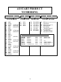
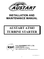
INSTALLATION AND
MAINTENANCE MANUAL
AUSTART ATS83
TURBINE STARTER
K.H. EQUIPMENT PTY. LTD.
14-16 WESTPOOL DRIVE,
HALLAM VICTORIA 3803 AUSTRALIA
PH: +61 3 9796 4766 FX: +61 3 9796 4878
EMAIL: [email protected] WEB: khequipment.com.au
Issue: 18/09/2002 Rev. 01
-1-
NOTICE
THIS MANUAL CONTAINS IMPORTANT SAFETY INFORMATION. IT IS IMPORTANT
THAT THE ENTIRE CONTENTS BE STUDIED BEFORE INSTALLATION AND OPERATION.
IT ONLY REFLECTS GENERIC INFORMATION RELATING TO A STANDARD AUSTART
ATS83 TURBINE STARTER. VARIOUS OTHER OPTIONS ARE AVAILABLE TO PROVIDE
INERTIA DRIVE SYSTEMS, HARSH ENVIRONMENT MUFFLERS OR THREADED
EXHAUSTS TO MEET SPECIFIC APPLICATION REQUIREMENTS.
FOREWORD
This manual contains instructions for the
installation, maintenance and operation of
your new ATS83 AUSTART Air Starter
Motor. It has been designed to provide
you with safe and reliable service.
However, it is both a pressure vessel and a
piece of rotating machinery. Therefore,
operators and maintenance personnel
must exercise good judgement and
appropriate safety practices to avoid
damage to the equipment and prevent
personal injury. The instructions in this
manual are intended for personnel with a
general training in the operation and
maintenance of air starter equipment.
It should be understood that the
information contained in this manual does
not relieve the operating and maintenance
personnel of the responsibility for
exercising good normal judgement in the
operation and care of air start equipment
and their associated systems.
CAUTION
An operating procedure, condition etc. that
if not followed could result in damage to,
or the destruction of equipment.
NOTICE
An operating procedure, condition etc. that
is essential to highlight and observe.
It is advisable that a safety program be
established to address the safety issues
detailed within this manual before
installing, operating or maintaining this
equipment. It is important such a program
covers the hazards associated with
compressed air.
! WARNING
Throughout this manual you will encounter
the words WARNING, CAUTION and
NOTICE.
Do not install this starter other than in
accordance with the instructions detailed
in this manual.
These
paragraphs
are
intended
to
emphasise certain areas where personnel
safety and satisfactory starter operation
may be compromised should the message
be ignored. The definitions of these words
are as follows -
These
instructions
should
be
read
completely before beginning installation
and should be available to personnel
responsible for operating and maintaining
this equipment. The unit is capable of
trouble free operation when properly
applied, installed and maintained.
Extra copies of this manual are available
from your local Austart Air Starter
Distributor or the Factory.
! WARNING
An operating procedure, practice etc. that
if not strictly observed, could result in
personal injury.
This manual is designed to cover all
situations normally experienced when
installing, operating and maintaining this
equipment. In the event situations are
encountered that are not covered by this
manual, consult your AUSTART agent or
K.H. Equipment Pty Ltd direct.
-2-
AUSTART PRODUCT
NUMBERING
STARTER MODEL
50
53
54
55
60
61
63
64
65
66
67
68
69
70
73
74
75
78
80
83
84
85
90
93
94
95
100
103
AS50
ATS53
ATS54
AS55
AS60
AS61
ATS63
ATS64
AS65
AS66
AS67
AS6070
AS69
AS70
ATS73
ATS74
AS75
AS7080
AS80
ATS83
ATS84
AS85
AS90
ATS93
ATS94
AS95
AS100
ATS103
(ATS53 OH)
(AS50 OH)
OBSOLETE
FLANGE CODE
01
02
03
04
SAE 1
SAE 2
SAE 3
SAE 4
(ATS63 OH)
OBSOLETE
PINION CODE
09
10
11
12
13
14
15
16
9TH 3MOD R
10TH 8/10 R
11TH 6/8 R
12TH 8/10 R
12TH 8/10 L
11TH 6/8 L
10TH 8/10 L
9TH 3MOD L
SPECIAL FEATURES
B
I
M
P
S
T
U
G
K
BCB (Beryllium Copper Bronze Pinion)
Inertia Drive
Mining Spec.(Cast Iron)
Motor Ports 90°
Short Muffler
Threaded Exhaust 3”
U Configuration
Threaded Exhaust 2”
Kelly Spinner Muffler
EXAMPLES OF BASIC STARTER PRODUCT NUMBERING
(AS67OH)
(ATS73 OH)
(AS70 OH)
630110M
630409M
730311
730314
730311I
730314I
730312M
PERKINS
MWM
DETROIT
DETROIT
DETROIT
DETROIT
CATERPILLAR
(ATS83 OH)
(AS80 OH)
(ATS93 OH)
(AS90 OH)
-3-
SAE1
SAE4
SAE3
SAE3
SAE3
SAE3
SAE3
10TH
9TH
11TH
11TH
11TH
11TH
12TH
MINING SPEC
MINING SPEC
LH
INERTIA DRIVE
INERTIA DRIVE LH
MINING SPEC
INSTALLATION AND PREPARATION FOR OPERATION
! WARNING
•
Ensure air supply is isolated before
installation, removal, maintenance or
adjustment of your AUSTART starter.
•
Before any starter is taken out of service
first bleed the Air Receiver of air and any
moisture that may have accumulated by
opening up the drain valve. Do not bleed
by removing Receiver plugs.
•
•
•
•
Always carry out a pressure test on the
complete starting system according to
Clause 8 on Page 5 before beginning
operation. Do not begin operations until
satisfied the unit has been installed
correctly.
•
Remove air hoses to ensure complete
safety once the air supply has been
isolated and the Receiver has been bled.
Always use recommended lubricants where
prescribed by this manual.
Under no
circumstances use flammable or volatile
liquids.
•
The Air Receiver must be manufactured to
an applicable pressure vessel code such as
AS 1210, or similar.
Ensure all fasteners are torqued to the
values prescribed in this manual.
Use
thread sealant where indicated.
•
To ensure warranty provisions are not
invalidated use only genuine AUSTART
replacement parts.
Non-genuine parts
may cause service and performance
problems and may affect the safe
operation of your starter.
Only use air hoses and fittings that are of
adequate size as indicated in the
installation schematic (page 6)
PRELIMINARY INSTALLATION REQUIREMENTS
Numbers in Brackets refer to Part Nos, refer to exploded view drawing on page 8
1. Your Austart Starter is flange mounted.
Before installing the starter carefully study
the mating position of the Austart Starter
and engine flanges to determine whether
the air inlet port orientation or Nose
Housing (48) geometry will suit your
particular installation. If not suitable reorientate as follows •
•
Carefully loosen the Band Clamp (12)
but do not remove. The two housings
can now be rotated relating to each
other without separation.
Re-orientate the Housings to the
desired position and torque the Band
Clamp (12) to 4 ft lb (6 Nm)
2. Ensure pinion is suitable for engine
application ie. correct pitch, diameter and
number of teeth.
4. Check Austart Starter clears all obstacles
and the flange mounts to flywheel housing
squarely without using undue force.
5. Ensure the hoses, fittings and starter ports
are clean and free from dirt and foreign
objects. Ensure they remain so during
installation.
6. For optimum Austart Starter performance
ensure air supply pipes or hoses have an
internal diameter of at least 1” (25mm),
refer Installation Schematic on page 6. In
the event line length must be longer than
15ft (5m), a size of 1-1/2” (40mm) should
be used. Keep the number of fittings and
the length of piping to a minimum. Avoid
the use of reducing bushes and other
fittings that could impede air flow.
3. Check flange to ring gear (FRG) spacing is
correct and that flange spacers are not
required. Pinion should be FRG less 1/8”
(3mm) when at rest.
-4-
INSTALLING THE STARTER AND PIPEWORK
Refer to the Starter Installation Schematic drawing on page 6
4. Mount the Starter Control Button SC25
onto
the
vehicle
dash-board
or
appropriate control panel and connect
to the Air Receiver using a minimum of
¼” (6mm) line.
1. The air supply line should ideally exit
from the top or side of the Air Receiver.
CAUTION
Do not connect Air Supply Line to the
bottom of the Air Receiver. Moisture
and system contaminants collect at the
receiver bottom and can damage the
Austart Starter internals if allowed to
pass through.
Periodically drain
moisture from the Air Receiver using a
drain valve connected at the Receiver
bottom.
NOTICE
Ensure the inlet side of the Starter
Control Button connects to the line from
the Receiver. Any Safety “Switches”
should be installed in this line between
the Starter Control Button and the Air
Receiver.
2. Install a 100 mesh ‘Y’ Strainer. A ‘Y’
Strainer installed before the Relay Valve
will provide protection to the Valve and
Austart Starter from contaminants that
may have accumulated in the Air
Receiver.
5. Determine the practicality of running
the 1” air supply hose or pipe from the
exit of the Relay Valve to the inlet of the
Austart Starter after the Austart Starter
is mounted. It may be easier to fit the
hose before the Austart Starter is
mounted in position.
NOTICE
6. Once the Austart Starter is mounted, fit
the remaining ¼” (6mm) control lines
from the Austart Starter to the Starter
Control Button and Relay Valve
respectively (Refer page 6).
Ensure the inlet side of the ‘Y’ Strainer
faces the Receiver, ie the direction
arrow points away from the Receiver.
7. Make all hose or pipe connections leak
proof using a suitable thread sealant.
3. Connect the RV1000 Relay Valve directly
on to the ‘Y’ Strainer using a 1” Short
Nipple.
8. Once the connections have been made
pressurise the system and check for
leaks using “soapy” water or similar
solution.
NOTICE
Ensure the inlet side of the Relay Valve
connects to the exit side of the ‘Y’
Strainer.
-5-
-6-
-7-
MAINTENANCE
! WARNING
DISASSEMBLY
Refer to the Cross Sectional and the Exploded View drawings on pages 8 & 10
Begin by removing the two Band Clamps
(12) and separate the three SubAssemblies; the Nose Assembly, the Motor
Assembly and the Silencer Assembly.
Gently tap the assemblies with a soft
hammer if necessary.
Motor Assembly
1. Remove Special Nut (15) and Washer
(16). Difficulty may be experienced and
it will be necessary to restrain the
Turbine Rotor (17) from turning by
using a ring spanner (wrench) on the
special flats provided.
The
Sub-Assemblies
may
now
be
dismantled separately. Disassembly of any
of these three Sub-Assemblies is detailed in
the exploded view on page 8 and is
basically in the order shown. Refer also to
the following instructions:
2. Remove Circlip (25) using circlip pliers
and press out Rotor Shaft (23) through
Rotor (17) as an Assembly.
3. Press out Seal Sleeve (19) and Bearing
(22) from Turbine Housing (18).
Nose Assembly
1. Remove Retainer (28), Planet Gears (29)
and Bearings (30). If necessary gently
tap the three Countersunk Screws (27)
to loosen them.
4. Press off Bearing (24) from the Rotor
Shaft (23).
2. Remove nine Screws (47) and separate
the Gear Case (35) by gently tapping it
with a soft hammer if necessary.
Silencer Assembly
Remove the three Nuts (1)
Assembly will easily come apart.
3. Remove the two Countersunk Screws
(36). The Bearing Housing (38) should
spring apart from the Nose Assembly.
Gently tap the Nose Housing (48) with a
soft hammer to assist it to separate if
necessary.
4. Remove Spring (45), Drive Assembly
(44) and Piston (41).
5. Remove Circlip (26) using circlip pliers
and Spider Hub Assembly (31).
6. Support Bearing Housing (38) in the
vertical position and gently press out
Drive Shaft (43) from Bearing (33).
7. Remove Circlip (32) using circlip pliers
and press out Bearing (33) and Seal
(34).
8. Remove Nose Bearing (50) and Seal (49)
from Nose Housing (48).
-8-
and
INSPECTION
Refer to the Cross Sectional and the Exploded View drawings on pages 8 & 10
1. Visually inspect all parts removed during
disassembly for excessive wear or
damage. Replace any damaged or
questionable parts.
CAUTION
Do not wash shielded bearings that are
to be reused in solvent or blow with
compressed air as it may remove
internal lubrication. Bearings that are
to be reused should be cleaned by
wiping the end shields with a clean
cloth.
2. Pay particular attention to the vanes on
End Cover (13) and Turbine Rotor (17)
and look for cracks, chipping, warpage
or excessive wear patterns. Rotor (17)
should fit tightly on to the Rotor Shaft
(23).
Replace
any
damaged
or
questionable parts. Remove burrs.
5. Clean all other parts that are going to be
reused with commercially approved
solvents.
3. Also pay particular attention to all gear
teeth looking for cracked or broken
teeth and excessive wear. Check the
pinion on the Drive Assembly (44) for
evidence of unusual contact patterns
resulting
from
misalignment
or
improper engagement. Remove any
burrs or replace if questionable.
! WARNING
Ensure cleaning operations are carried
out in a properly vented area away from
open flames.
4. Check all bearings are free to rotate and
do not have excessive play between
races. If in doubt replace questionable
bearings.
6. It is recommended that when servicing
your Austart Turbine Starter always
replace complete repair kit contents.
-9-
REASSEMBLY
Refer to the Cross Sectional and the Exploded View drawings on pages 8 & 10
Reassembly of any of the three SubAssemblies detailed in the exploded view
on page 8 is basically in the reverse order
shown. Refer also to the following
instructions:
9.
Nose Assembly
1. Begin by pressing the Bearing (50) and
Seal (49) into Nose Housing (48) using a
press with an appropriate pressing tool.
Liberally coat the inner regions of Nose
Assembly (48) and Bearing (50) with
grease and assemble Nose Assembly
over Piston (41) taking care not to
damage Wiper Seal (42). Rotate the
Nose
Assembly
until
the
two
countersunk screw holes line up
between the nine main stud holes.
10. Squeeze together Bearing Housing (38)
and Nose Assembly (48) being careful
not to damage O-Ring (40), then insert
Countersunk Screws (36).
2. Drive home the Seal (34) into the
Bearing Housing (38) until it bottoms.
11. Slide Gear Case (35) onto Bearing
Housing (38) ensuring O-Ring (37) is
not damaged by smearing oil on the ORing (37) to allow Gear Case (35) to
easily slide over.
CAUTION
Ensure the Seal (34) is fitted the correct
way, ie with the tapered leading edge
engaged first. Liberally grease the exposed
side of the Seal (34) with Lithium based
grease such as Valvoline VALPLEX EP
Grease or similar.
12. Line up set screw holes and install nine
Setscrews (47).
13. Invert the built up Nose Assembly and
restrain in the vertical position. Install
the three Planet Gears (29) and gear
Bearings (30) onto the Spider Hub
Assembly (31).
3. Using a press drive home the Bearing
(33) into the Bearing Housing (38) until
it bottoms. Then insert Shaft (43) into
the Bearing (33) and press home.
Ensure the Bearing Housing (38) is
adequately
supported
during
this
operation. Finally fit Circlip (32) using
circlip pliers.
Coat gear bearings with grease before
assembly.
4. Slip on Spider Hub Assembly (31) onto
Shaft (43) and fit Circlip (26) using
circlip pliers.
CAUTION
Ensure Planet Gears are installed with
the boss side of the Gear facing the
Spider Hub.
5. Fit O-Rings (37) and (39) onto Bearing
Housing (38).
6. Fit O-Ring (40) and Wiper Seal (42) onto
Piston (41).
14. Install Retainer (28) to the Spider Hub
Assembly (31) and install the three
Countersunk Screws (27).
7. Liberally grease Piston (41), the inner
portion of the Bearing Housing (38) and
Shaft (43) where it extends, then gently
slide Piston (41) onto the Bearing
Housing without damaging O-Ring (39).
15. Liberally pack gear teeth with suitable
grease such as Valvoline Valplex EP or
similar.
16. The Nose Assembly is now ready to
accept the Motor Assembly.
8. Slide Drive Assembly (44) onto Shaft
(43) and then fit Spring (45) over Drive
Assembly (44).
- 10 -
Motor Assembly
Assembling Nose and
Motor Assemblies
1. Begin by lightly oiling the internal bore
of the Turbine Housing (18) with
hydraulic oil and fitting inner O-Ring
(21).
1. Apply grease to Planet Gears (29) and
Gear Case (35). Carefully line up spline
of Motor Assembly Shaft (23) with the
Planet Gears (29) on the Nose Assembly
and slide the Nose Assembly home.
2. Evenly press home Bearing (22) until it
bottoms.
Ensure O-Ring (21) is not
damaged or dislodged.
2. Line up the Nose Assembly and Motor
Assembly air inlet ports and install Band
Clamp (12). Tighten Band Clamp (12) to
4 ft lb (6 Nm).
3. Install Piston Rings (20) onto Seal
Sleeve (19). Rotate Piston Rings (20) so
that the gaps are 1800 apart.
3. Test the operation of the Drive Assembly
(44) by introducing air pressure at the
control line inlet port.
The Drive
Assembly should move freely forward
when air pressure is applied and back
once the pressure has been relieved.
Investigate if this movement is not
smooth.
4. Lightly grease the outside of the Piston
Rings (20) on the Seal Sleeve (19) and
push home into the Turbine Housing
(18) until it bottoms.
5. Press Bearing (24) onto Rotor Shaft (23)
using a press and liberally grease top of
bearing.
4. The Nose/Motor Assembly is now ready
to accept the Silencer Assembly.
6. Install 2nd O-Ring (21) into Turbine
Housing (18) and insert Rotor Shaft (23)
and Bearing (24) as an assembly. This
should be achieved with an even push
fit.
Adding Silencer Assembly
7. Install Circlip (25) with circlip pliers.
1. Install Silencer Assembly to the Turbine
Housing (18). Install Band Clamp (12).
Tighten Band Clamp (12) to 4 ft lb (6
Nm)
8. Fit Turbine Rotor (17) onto Rotor Shaft
(23) extension.
9. Lightly oil thread on Rotor Shaft (23)
extension and install Washer (16) and
Special Nut (15). Tighten Nut against
the Turbine Rotor (17) to a torque of 2530 ft lb.(30-40 Nm) Prevent the Rotor
from turning by using a ring spanner
(wrench) on the special flats provided.
2. The Austart Air Starter is now assembled
and ready for installation.
Refer
Installation and Operation section of this
manual.
- 11 -
WARRANTY POLICY
All Austart Products supplied by K.H. Equipment Pty. Ltd. (herein called “the Manufacturer”) is
warranted to be free from any defect in workmanship and material under conditions of normal
use and service for engine starting applications for a period of 12 months from the date of
purchase by the first user. Normal wear and tear is excluded from the warranty cover.
The Manufacturer will replace or repair at their works, without cost, any Austart Starter or
parts found to be defective or at their discretion choose to refund the purchase price less a
reasonable allowance for depreciation in exchange for the starter or part should the item prove
impossible to repair or replace.
This warranty shall not apply to any Austart Starter or parts which have been altered or
repaired or purchased outside the Manufacturer and its assigned agents nor to equipment or
parts that have been subject to misuse including overloading, neglect, accident or damage, nor
to any part or parts improperly applied or installed.
This warranty is in lieu of all other warranties and conditions statutory or otherwise expressed
or implied and of all other obligations or liabilities on the Manufacturer’s part. The
Manufacturer’s maximum liability is limited to the purchase price of the starter and is not liable
for any consequential damage, loss or expense.
Repeat engine starting attempts must be delayed for 15 seconds to allow all Austart Starter
and engine components to stop rotating to avoid damage or adverse wear of components.
_____________________________________________________________________________________________
DISTRIBUTED BY
- 12 -