1
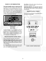
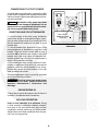
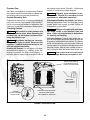
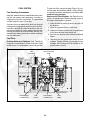
Operator Manual
Commercial Mobile Generator Set
HDKAL
HDKAS
English
7-2009
981−0104 (Issue 3)
California
Proposition 65 Warning
Diesel engine exhaust and some of its constituents are known
to the State of California to cause cancer, birth defects, and
other reproductive harm.
Table of Contents
SAFETY PRECAUTIONS . . . . . . . . . . . . . . . . . . . . . . . . . . . . . . . . . . . . . . . . . . . . . . . . . . . . . 2
INTRODUCTION . . . . . . . . . . . . . . . . . . . . . . . . . . . . . . . . . . . . . . . . . . . . . . . . . . . . . . . . . . . . 4
About this Manual . . . . . . . . . . . . . . . . . . . . . . . . . . . . . . . . . . . . . . . . . . . . . . . . . . . . . 4
Model Identification . . . . . . . . . . . . . . . . . . . . . . . . . . . . . . . . . . . . . . . . . . . . . . . . . . . . 4
Fuel Recommendations . . . . . . . . . . . . . . . . . . . . . . . . . . . . . . . . . . . . . . . . . . . . . . . . 4
Engine Oil Recommendations . . . . . . . . . . . . . . . . . . . . . . . . . . . . . . . . . . . . . . . . . . . 5
Batteries . . . . . . . . . . . . . . . . . . . . . . . . . . . . . . . . . . . . . . . . . . . . . . . . . . . . . . . . . . . . . 5
Genset-Mounted Control Panel . . . . . . . . . . . . . . . . . . . . . . . . . . . . . . . . . . . . . . . . . 5
Remote Control Panels . . . . . . . . . . . . . . . . . . . . . . . . . . . . . . . . . . . . . . . . . . . . . . . . 5
OPERATION . . . . . . . . . . . . . . . . . . . . . . . . . . . . . . . . . . . . . . . . . . . . . . . . . . . . . . . . . . . . . . . . 6
Pre-Start Checks . . . . . . . . . . . . . . . . . . . . . . . . . . . . . . . . . . . . . . . . . . . . . . . . . . . . . . 6
Starting . . . . . . . . . . . . . . . . . . . . . . . . . . . . . . . . . . . . . . . . . . . . . . . . . . . . . . . . . . . . . . 6
Stopping . . . . . . . . . . . . . . . . . . . . . . . . . . . . . . . . . . . . . . . . . . . . . . . . . . . . . . . . . . . . . 7
Powering Appliances . . . . . . . . . . . . . . . . . . . . . . . . . . . . . . . . . . . . . . . . . . . . . . . . . . 7
Connections to Utility Power . . . . . . . . . . . . . . . . . . . . . . . . . . . . . . . . . . . . . . . . . . . . 8
Resetting Line Circuit Breakers . . . . . . . . . . . . . . . . . . . . . . . . . . . . . . . . . . . . . . . . . 8
Engine Break-In . . . . . . . . . . . . . . . . . . . . . . . . . . . . . . . . . . . . . . . . . . . . . . . . . . . . . . . 8
No-load Operation . . . . . . . . . . . . . . . . . . . . . . . . . . . . . . . . . . . . . . . . . . . . . . . . . . . . . 8
Genset Exercise . . . . . . . . . . . . . . . . . . . . . . . . . . . . . . . . . . . . . . . . . . . . . . . . . . . . . . 9
Genset Storage . . . . . . . . . . . . . . . . . . . . . . . . . . . . . . . . . . . . . . . . . . . . . . . . . . . . . . . 9
Returning Genset to Service . . . . . . . . . . . . . . . . . . . . . . . . . . . . . . . . . . . . . . . . . . . . 9
PERIODIC MAINTENANCE SCHEDULE . . . . . . . . . . . . . . . . . . . . . . . . . . . . . . . . . . . . . . 10
MAINTENANCE PROCEDURES . . . . . . . . . . . . . . . . . . . . . . . . . . . . . . . . . . . . . . . . . . . . . 11
General Inspection . . . . . . . . . . . . . . . . . . . . . . . . . . . . . . . . . . . . . . . . . . . . . . . . . . . 11
Changing Oil and Oil Filter . . . . . . . . . . . . . . . . . . . . . . . . . . . . . . . . . . . . . . . . . . . . . 12
Air Cleaner Maintenance . . . . . . . . . . . . . . . . . . . . . . . . . . . . . . . . . . . . . . . . . . . . . . 13
Spark Arrestor Cleaning . . . . . . . . . . . . . . . . . . . . . . . . . . . . . . . . . . . . . . . . . . . . . . . 13
Batteries . . . . . . . . . . . . . . . . . . . . . . . . . . . . . . . . . . . . . . . . . . . . . . . . . . . . . . . . . . . . 13
Engine Cooling System . . . . . . . . . . . . . . . . . . . . . . . . . . . . . . . . . . . . . . . . . . . . . . . 14
Fuel System . . . . . . . . . . . . . . . . . . . . . . . . . . . . . . . . . . . . . . . . . . . . . . . . . . . . . . . . . 16
TROUBLESHOOTING . . . . . . . . . . . . . . . . . . . . . . . . . . . . . . . . . . . . . . . . . . . . . . . . . . . . . . 18
Engine Does Not Crank . . . . . . . . . . . . . . . . . . . . . . . . . . . . . . . . . . . . . . . . . . . . . . . 18
Engine Cranks But Does Not Start . . . . . . . . . . . . . . . . . . . . . . . . . . . . . . . . . . . . . 19
Fault Shutdown . . . . . . . . . . . . . . . . . . . . . . . . . . . . . . . . . . . . . . . . . . . . . . . . . . . . . . 19
Engine Lacks Power or Unstable . . . . . . . . . . . . . . . . . . . . . . . . . . . . . . . . . . . . . . 20
No Output Voltage . . . . . . . . . . . . . . . . . . . . . . . . . . . . . . . . . . . . . . . . . . . . . . . . . . . . 20
SPECIFICATIONS . . . . . . . . . . . . . . . . . . . . . . . . . . . . . . . . . . . . . . . . . . . . . . . . . . . . . . . . . . 22
INFORMATION FOR CALIFORNIA GENSET USERS . . . . . . . . . . . . . . . . . . . . . . . . . . . 23
HOW TO OBTAIN SERVICE . . . . . . . . . . . . . . . . . . . . . . . . . . . . . . . . . . . . . . . . . . . . . . . . . 24
MAINTENANCE RECORD . . . . . . . . . . . . . . . . . . . . . . . . . . . . . . . . . . . . . . . . . . . . . . . . . . . 25
1
Safety Precautions
Thoroughly read the OPERATOR’S MANUAL
before operating the genset. Safe operation and
top performance can be obtained only by proper operation and maintenance.
cally live parts can cause severe personal injury or death.
The following symbols in this Manual alert you to
potential hazards to the operator, service personnel
and equipment.
• Used engine oil has been identified by some
state and federal agencies as causing cancer
or reproductive toxicity. Do not ingest, inhale,
or contact used oil or its vapors.
alerts you to an immediate hazard
which will result in severe personal injury or
death.
• Do not work on the genset when mentally or
physically fatigued or after consuming alcohol
or drugs.
alerts you to a hazard or unsafe
practice which can result in severe personal injury or death.
• Carefully follow all applicable local, state and
federal codes.
CAUTION alerts you to a hazard or unsafe
practice which can result in personal injury or
equipment damage.
• Generator output connections must be made
by a qualified electrician in accordance with applicable codes.
Electricity, fuel, exhaust, moving parts and batteries
present hazards which can result in severe personal injury or death.
• The genset must not be connected to the public
utility or any other source of electrical power.
Connection could lead to electrocution of utility
workers, damage to equipment and fire. An approved switching device must be used to prevent interconnections.
WARNING
GENERATOR VOLTAGE IS DEADLY!
GENERAL PRECAUTIONS
• Keep ABC fire extinguishers handy.
• Make sure all fasteners are secure and torqued
properly.
• Use caution when working on live electrical
equipment. Remove jewelry, make sure clothing and shoes are dry and stand on a dry wooden platform on the ground or floor.
• Keep the genset and its compartment clean.
Excess oil and oily rags can catch fire. Dirt and
gear stowed in the compartment can restrict
cooling air.
FUEL IS FLAMMABLE AND EXPLOSIVE
• Keep flames, cigarettes, sparks, pilot lights,
electrical arc-producing equipment and
switches and all other sources of ignition well
away from areas where fuel fumes are present
and areas sharing ventilation.
• Let the engine cool down before removing the
coolant pressure cap or opening the coolant
drain. Hot coolant under pressure can spray
out and cause severe burns.
• Before working on the genset, disconnect the
negative (−) battery cable at the battery to prevent starting.
• Fuel lines must be secured, free of leaks and
separated or shielded from electrical wiring.
• Use approved non-conductive flexible fuel
hose for fuel connections at the genset.
• Use caution when making adjustments while
the genset is running—hot, moving or electri-
2
ENGINE EXHAUST IS DEADLY!
BATTERY GAS IS EXPLOSIVE
• Learn the symptoms of carbon monoxide poisoning in this manual.
• Wear safety glasses and do not smoke while
servicing batteries.
• Never sleep in the vehicle while the genset is
running unless the vehicle has a working carbon monoxide detector.
• When disconnecting or reconnecting battery
cables, always disconnect the negative (−) battery cable first and reconnect it last to reduce
arcing.
• The exhaust system must be installed in accordance with the genset Installation Manual.
DO NOT OPERATE IN FLAMMABLE AND
EXPLOSIVE ENVIRONMENTS
• Do not use engine cooling air to heat the vehicle interior.
Flammable vapor can cause a diesel engine to
overspeed and become difficult to stop, resulting in
possible fire, explosion, severe personal injury and
death. Do not operate a diesel-powered genset
where a flammable vapor environment can be
created by fuel spill, leak, etc., unless the genset is equipped with an automatic safety device
to block the air intake and stop the engine. The
owners and operators of the genset are solely responsible for operating the genset safely. Contact
your authorized Cummins Onan dealer or distributor for more information.
• Make sure there is ample fresh air when operating the genset in a confined area.
MOVING PARTS CAN CAUSE SEVERE
PERSONAL INJURY OR DEATH
• Do not wear loose clothing or jewelry near moving parts such as PTO shafts, fans, belts and
pulleys.
• Keep hands away from moving parts.
• Keep guards in place over fans, belts, pulleys,
etc.
mobile-5
3
Introduction
ABOUT THIS MANUAL
This manual covers operation and maintenance of
the model HDKAL and HDKAS generator sets (gensets). Study this manual carefully and observe all of
its instructions and precautions. Using the genset
properly and maintaining it regularly will promote
longer genset life, better performance, and safer
operation. Each operator should become thoroughly familiar with this manual. Keep this manual
in a convenient location for quick reference.
MODEL IDENTIFICATION
When you call for service or parts have the genset
model number and serial number ready (Figure 1).
For ready reference, record these numbers in the
boxes shown.
FUEL RECOMMENDATIONS
WARNING Diesel fuel is combustible and can
cause severe personal injury or death. Do not
smoke near fuel tanks or fuel-burning equipment or in areas sharing ventilation with such
equipment. Keep flames, sparks, pilot flames,
electrical arcs and switches and all other
sources of ignition well away. Keep a type ABC
fire extinguisher handy.
RECORD MODEL AND SERIAL NUMBERS HERE
MODEL NUMBER
Use clean, fresh No. 2 diesel fuel (ASTM 2-D) when
the outdoor ambient temperature is above freezing,
and No. 1 diesel fuel (ASTM 1-D) when below
freezing. The fuel should have a Cetane number of
at least 45 for reliable starting.
SERIAL NUMBER
FIGURE 1. TYPICAL NAMEPLATE
Note: Only low sulfer diesel or Ultra Low Sulfur Diesel (ULSD) fuel that meets the ASTM D975 or EN 590
standard for lubricity may be used with this engine.
The 1 to 2 percent less energy content of the fuel can
have a slight effect on maximum engine power.
Note: B5 Bio-Diesel fuel that meets industry specifications and quality is suitable for use with this engine.
4
ENGINE OIL RECOMMENDATIONS
Hour Meter: Indicates the number of hours the genset has run. It cannot be reset.
Use premium quality motor oil. Look for the API
(American Petroleum Institute) classification and
use Class CF-4 or CF or better oil. Also look for the
SAE (Society of Automotive Engineers) viscosity
grade. Referring to Figure 2, choose the viscosity
grade appropriate for the range of ambient temperatures expected before the next scheduled oil
change. Multi-grade oils such as SAE 15W-40 are
recommended for year-round use.
Fault Reset Breaker: Trips and shuts down the
genset when there is a low oil pressure or high coolant temperature fault condition. Reset by pushing in
the red button.
REMOTE CONTROL PANELS
Remote control panels with a control switch and engine gauges are available.
S
S
t
t
o
a
p
r
t
FIGURE 2. SAE VISCOSITY GRADE vs. AMBIENT
TEMPERATURE
BATTERIES
DC
The genset requires a 12 volt battery to power its
control and starting circuits. Reliable genset starting and starter service life depend upon adequate
battery system capacity and maintenance. See
Specifications for battery requirements and Periodic Maintenance for battery care.
Control
Brkr
GENSET-MOUNTED CONTROL PANEL
Figure 3 illustrates the genset control panel.
Start-Stop-Preheat Switch (S1): Starts the genset
when held at Start and stops the genset when momentarily touched to Stop. Holding the switch at
Stop causes the glow plugs to preheat the combustions chambers.
DC Control Breaker: Protects the control circuits
from shorts to ground. Can be used as an emergency stop switch. Reset with handle.
Fault
Brkr
FIGURE 3. GENSET CONTROL PANEL
5
Operation
EXHAUST GAS IS DEADLY!
Engine exhaust contains carbon monoxide, a poisonous, odorless and colorless gas that can
cause unconsciousness and death. Symptoms of carbon monoxide poisoning include:
• Dizziness
• Throbbing in Temples
• Nausea
• Muscular Twitching
• Headache
• Vomiting
• Weakness
• Trouble Thinking Clearly
• Sleepiness
GET EVERYONE OUT INTO FRESH AIR IMMEDIATELY IF ANYONE EXPERIENCES ANY OF
THESE SYMPTOMS. Seek medical attention if symptoms persist.
Never sleep in the vehicle when the genset is running unless the vehicle has an operating
carbon monoxide detector.
Look and listen for leaks along the entire run of the exhaust system every time you start up the
genset and every eight hours if the genset is being run continuously. Shut down the genset
immediately if there is a leak and do not run it until the leak has been repaired.
The installation of the exhaust system must be in accordance with the genset Installation
Manual.
PRE-START CHECKS
Do not crank for more than 15 seconds at a
time. Wait two minutes before trying again. See
Troubleshooting if the engine does not start on
the second try.
Perform General Inspection (p. 11). Check for
fuel, exhaust, oil and coolant leaks every eight
hours if the genset is being run continuously.
CAUTION Excessive cranking can overheat and damage the starter. Do not crank
for more than 15 seconds at a time and wait
two minutes before trying again.
Check the Maintenance Record and perform any
maintenance due (Periodic Maintenance Schedule). Also see GENSET BREAK-IN if the genset is
new and RETURNING THE GENSET TO SERVICE if the vehicle has been in storage.
4. Connect the electrical loads after the genset
has warmed up for a few minutes.
STARTING
5. Check for fuel, exhaust, oil and coolant leaks
and complete General Inspection (p. 11).
Check the engine gauges regularly (if provided) while the genset is running.
1. Disconnect all loads from the genset.
2. Preheat − Hold the control switch in the PREHEAT position for the following number of seconds depending on ambient temperature:
• Oil Pressure Gauge: Normal engine oil
pressure is 28 − 64 psi (194 − 442 kPa) at
normal operating temperature.
10 seconds—above 50° F (10° C)
15 seconds—0° F to 50° F (−17° to 10° C)
20 seconds—below 0° F (−17° C)
• DC Voltmeter: Normal DC system voltage
is 12.5 − 15 volts depending on battery
condition and state-of-charge.
CAUTION Preheat times longer than 20
seconds can damage the glow plugs.
• Coolant Temperature Gauge: Normal
engine
coolant
temperature
is
160 −195° F (71 − 91° C) depending on
load and ambient temperature.
3. Start − Immediately after PREHEAT push the
control switch to START and hold it there until
the engine starts. The starter will automatically
disconnect as the engine starts up.
6
STOPPING
TABLE 1. TYPICAL APPLIANCE LOADS
Appliance
Before stopping let the genset cool down by running at no-load for three to five minutes. Then touch
the control switch momentarily to STOP.
Load (watt)
Air Conditioner
1400-2000
Battery Charger
Up to 800
DC Converter
300-1500
Refrigerator
600-1000
Microwave Oven
1000-1500
Electric Frying Pan/Wok
1000-1500
Electric Stove Element
350-1000
The genset can power AC motors, air conditioners,
AC/DC converters and other appliances. How
much appliance load* can be serviced depends
upon the genset power rating. The genset will shut
down or its circuit breakers will trip if the sum of the
loads exceeds genset rating.
Electric Water Heater
1000-1500
Electric Iron
500-1200
Electric Hair Dryer
800-1500
Coffee Percolator
550-750
Television
200-600
To avoid overloading the genset and causing shutdowns, compare the sum of the loads of the appliances that are likely to be used at the same time
to the power rating of the genset. Use Table 1 or the
ratings on the appliances themselves (if so marked)
to obtain the individual appliance loads. It may be
necessary to run fewer appliances at the same
time so that the sum of the loads is not greater
than genset rating.
Radio
50-200
Electric Drill
250-750
Electric Broom
200-500
Electric Blanket
50-200
CAUTION Failure to let the engine cool down
before stopping can lead to engine damage. Let
the genset run three to five minutes at no-load
before stopping.
POWERING APPLIANCES
TABLE 2. MAXIMUM POWER VS. ALTITUDE
Note that the genset may shut down due to overload, even though the sum of the loads is less than
genset rating, when a large motor or air conditioner
is started last or cycles off and then on again. The
reason for this is that motor startup load is much
larger than running load. It may be necessary to
run fewer appliances when large motors and air
conditioners are cycling on and off.
Elevation above Sea
Level
at/below 500 ft (152 m)
7500 W (rated)
at 2500 ft (762 m)
7050 W
at 5500 ft (1676 m)
6375 W
above 5500 ft (1676 m)
Note that air density decreases as altitude increases, decreasing engine power. Power decreases approximately 3 percent of rated power every 1000 feet (305 m) that elevation increases
above sea level. See Table 2 for typical calculations. It may be necessary to operate fewer appliances at higher altitudes.
Maximum Power
6375 W minus 225 W
every 1000 ft (305 m)
* Appliance load and genset power are measured in terms of watt (W) or kilowatt (kW), where 1 kilowatt (kW) = 1000 watt (W).
7
CONNECTIONS TO UTILITY POWER
A vehicle that has provisions for connection to utility
power must be equipped with an approved transfer
switch to keep the genset and utility power from being interconnected.
WARNING Backfeed to utility power can cause
electrocution and damage to equipment. Use an
approved device to prevent the genset from being interconnected with utility power.
RESETTING LINE CIRCUIT BREAKERS
LINE CIRCUIT
BREAKER RESET
HANDLES
If a circuit breaker in the main power distribution
panel in the vehicle or on the genset (Figure 4) trips,
there is either a short circuit or too much load. Note
that the genset will continue to run after a circuit
breaker trips.
FIGURE 4. GENSET MOUNTED LINE CIRCUIT
BREAKERS
If a circuit breaker trips, disconnect or turn off as
many appliances as possible and reset the circuit
breaker. (Push the circuit breaker OFF to reset it
and then ON to reconnect the circuit.) If the circuit
breaker trips right away, either the electrical distribution system has a short or the circuit breaker is
faulty. Call a qualified electrician.
If the circuit breaker does not trip, reconnect a combination of appliances that does not overload the
genset or cause the circuit breaker to trip. An appliance that causes a circuit breaker to trip right
away probably has a short.
Electrical appliances must be properly grounded
and in good working condition.
WARNING Electrical shock can cause severe
personal injury or death. Read and follow the
appliance manufacturer’s instructions and
warnings.
ENGINE BREAK-IN
Change the oil and oil filter after the first 50 hours of
operation. See Maintenance Procedures.
NO-LOAD OPERATION
Keep no-load operation to a minimum. During
no-load operation combustion chamber temperatures drop to the point where fuel does not burn
completely, causing slobbering and white smoke.
Always have some load connected when the genset is run for long periods.
8
GENSET EXERCISE
last—Wear
safety
glasses—Do
not
smoke—Switch lights ON and Off away
from the battery.
If use is infrequent, run the genset at approximately
1/2 rated power for an hour every week. Exercising
the genset results in better starting, longer engine
life and increased genset reliability by driving off
moisture, re-lubricating the engine, using up fuel
before it becomes stale and removing oxides from
electrical contacts. One longer period during which
the engine and generator warm up thoroughly is
better than several shorter periods.
3. Disconnect the battery cables (negative [−]
cables first) and store the battery(ies) in accordance with the manufacturer’s recommendations.
Hot coolant is under pressure
and can cause severe burns when loosening the pressure cap. Let the engine cool
before loosening the pressure cap.
WARNING
GENSET STORAGE
4. Check the coolant level and add coolant as
necessary. Test the coolant mixture if freezing
temperatures are possible and change if necessary. See ENGINE COOLING SYSTEM in
Maintenance Procedures.
If the genset will be inactive for more than 30 days
and it is impractical to have someone exercise it,
prepare it for storage as follows:
1. Run the genset until it has thoroughly warmed
up and shut it down.
5. Clean the genset and lightly oil parts that can
rust.
Crankcase pressure can blow
out hot oil and cause severe burns. Stop the
engine before checking the oil level or
opening the fill cap.
WARNING
RETURNING GENSET TO SERVICE
1. Check the tag on the dipstick and change the
oil if the viscosity is not suitable for present and
anticipated ambient temperatures.
2. Change the oil and oil filter while still warm and
attach a tag to the dip stick indicating the oil viscosity grade. See CHANGING OIL AND OIL
FILTER in Maintenance Procedures.
2. Reconnect the battery(ies) (negative [−] cables
last) and service as necessary in accordance
with the manufacturer’s instructions.
Arcing at battery terminals or in
a light switch or other equipment, flames
and sparks can ignite battery gas causing
severe personal injury. Ventilate the battery
compartment before connecting or disconnecting battery cables—Disconnect the
negative (−) cable first and reconnect it
WARNING
3. Prime the fuel system (p. 17).
4. Perform PRE-START CHECKS and start and
run the genset according to STARTING. Perform maintenance or service as required before placing the genset in service.
9
Periodic Maintenance Schedule
Periodic maintenance is essential for top genset
performance and long service life. Use Table 3 as a
guide, follow Maintenance Procedures and record
maintenance performed in Maintenance Record.
WARNING Accidental starting can cause severe personal injury or death. Disconnect the
negative (−) cable(s) at the battery(ies) to prevent starting while working on the genset.
TABLE 3. PERIODIC MAINTENANCE SCHEDULE
FREQUENCY
PROCEDURE
After
first
50 Hrs
Every
Day/
8 Hrs
Every
50 Hrs
P
a
Every Every 6 Every
Month/ Month/
Year/ Every 2 Every g
100 Hrs 250 Hrs 500 Hrs Years 5 years e
Inspect Genset
x1
11
Check Oil Level
x
11
Check Coolant Level
x
11
Check Fuel Level
x
11
Clean Spark Arrestor
x
13
Clean Air Cleaner Dust Boot
x5
13
Check Battery
x2
13
Check V-Belt Tension
x3
14
Drain Water in Fuel
x4
16
x5
12
Change Engine Oil and Oil
Filter
x
Change Fuel Filter
x
16
Change Air Cleaner Element
x5
13
Change Coolant
x
14
Adjust Valve Lash
x6
−
Replace Pressure Cap
x
14
x6
Replace Generator Bearing
1 − Check for oil, fuel, coolant and exhaust system leaks.
2 − See battery manufacturer’s recommendations.
3 − Check for slippage.
4 − Drain about one cup to remove water and sediment.
5 − Perform more often in dusty conditions.
6 − Must be performed by an authorized Cummins Onan dealer.
10
−
Maintenance Procedures
GENERAL INSPECTION
vehicles can cause exhaust gases to accumulate in
and around the vehicle.
Perform these checks and inspections every time
the genset is started or every eight hours if the genset is being run continuously.
To avoid drawing exhaust gases into the vehicle, do
not turn on power ventilators or exhaust fans when
the genset is running and the vehicle is standing
still.
Oil Level Check
WARNING EXHAUST GAS IS DEADLY! Do not
operate the genset if there is an exhaust leak or
any danger of exhaust gases entering or being
drawn into the vehicle.
Crankcase pressure can blow out
hot oil and cause severe burns. Stop the engine
before checking the oil level or opening the fill
cap.
WARNING
WARNING Do not park the vehicle in high
grass or brush. Contact with the exhaust system can cause a fire.
Shut down the genset to check engine oil level and
wait a few minutes for the oil to drain down to the
crankcase to get an accurate indication of oil level.
Fuel System Inspection
Keep the oil level between FULL and ADD on the
dipstick (Figure 5). See ENGINE OIL RECOMMENDATIONS (p. 5) for the oil to use.
Check for leaks at all fuel line fittings and gaskets.
Replace fuel hose that has been abraded or cut and
install new hose in such a way that it will not become
kinked, rub against other parts or come in contact
with sharp edges, hot surfaces or wiring.
CAUTION Too little oil can lead to severe engine damage and too much oil to high oil consumption and foaming, which can cause engine
shutdown. Keep the oil level between FULL and
ADD.
WARNING Fuel leaks can lead to fire. Repair
leaks immediately. Do not run the genset if it
causes fuel to leak.
Coolant Level Check
Prime the fuel system if the genset ran out of fuel or
a fuel filter was replaced. See FUEL SYSTEM.
Replenish the normal loss of coolant by keeping the
level in the coolant recovery tank between COLD
and HOT. See COOLING SYSTEM for the recommended mixture of antifreeze and if it is necessary
to refill the system.
Battery Inspection
Check for clean, tight battery connections. Loose
and corroded connections make for hard starting
because of high electrical resistance. See BATTERIES.
Exhaust Leaks
Look and listen for exhaust system leaks while the
genset is running. Shut down the genset if a leak is
found and have it repaired before operating the
genset.
WARNING Arcing at battery terminals or in a
light switch or other equipment, flames and
sparks can ignite battery gas causing severe
personal injury. Ventilate the battery compartment before connecting or disconnecting battery cables—Disconnect the negative (−) cable
first and reconnect it last—Wear safety
glasses—Do not smoke—Switch lights ON and
Off away from the battery.
Look for openings or holes between the genset
compartment and vehicle cab or living space if the
genset engine sounds louder than usual. Have all
such openings or holes closed off or sealed to prevent exhaust gases from entering the vehicle.
Replace dented, bent or severely rusted sections of
the tailpipe and make sure the tailpipe extends at
least 1 inch (25.4 mm) beyond the perimeter of the
vehicle.
Mechanical Inspection
Check for unusual noises and vibrations, loose genset mounts and signs of mechanical damage.
Check the engine gauges regularly (if provided)
while the genset is running. See Operation for normal gauge readings.
Park the vehicle so that the genset exhaust gases
can disperse away from the vehicle. Barriers such
as walls, snow banks, high grass, brush and other
11
Keep the genset clean. Do not clean the genset
while it is running. Protect the generator, control
panel, and electrical connections from cleaning solvents. Remove the generator endbell cover and use
compressed air to blow dust out of the generator
and radiator core.
the oil into a suitable container and close the valve
when the oil has completely drained.
Changing Oil Filter: To change the oil filter, place a
container under the oil filter (Figure 5) to catch oil
that drips out and then spin off the oil filter. Clean the
filter mounting surface (making sure to remove the
old gasket), apply oil to the new filter gasket and
spin the filter on until the gasket just touches the
mounting pad. Then tighten an additional 3/4 turn.
WARNING Wear safety glasses when using
compressed air to prevent eye injury.
CHANGING OIL AND OIL FILTER
Refilling Engine Oil: See ENGINE OIL RECOMMENDATIONS (p. 5) for the oil to use and
Specifications for the amount. Refill with the proper
amount of oil, start the engine and check for leakage around the filter gasket. Tighten the filter only
enough to stop leakage. Shut off the genset, recheck the oil level and add oil as necessary. Secure
the access door.
WARNING State and federal agencies have determined that contact with used engine oil can
cause cancer or reproductive toxicity. Take care
to limit skin contact and breathing of vapors.
Use protective gloves and wash exposed skin.
See Table 3 for frequency of maintenance.
CAUTION Too little oil can lead to severe engine damage and too much oil to high oil consumption and foaming, which can cause engine
shutdown. Keep the oil level between FULL and
ADD.
WARNING Crankcase pressure can blow out
hot oil and cause severe burns. Stop the engine
before checking the oil level or opening the fill
cap.
Draining Engine Oil: To drain the engine oil, run
the engine until thoroughly warm and stop it. Open
either the side or bottom service access door to get
at the oil drain valve and oil filter (Figure 5). Drain
Disposing of Used Oil and Oil Filter: Dispose of
the used oil and oil filter according to local environmental regulations.
OIL DIPSTICK
(BOTH SIDES)
OIL FILL
OIL FILTER
OIL DRAIN VALVE
FIGURE 5. OIL CHECK, FILL, DRAIN AND FILTER
12
SERVICE ACCESS DOORS
AIR CLEANER MAINTENANCE
See Table 3 for frequency of maintenance. The air
cleaner element must be handled carefully and
must never have oil applied to it. Before changing
the filter element, squeeze the dust boot to release
any trapped dust. Install the new filter element as
follows:
1. Unclip the cover (Figure 6) and pull the filter
element out gently to reduce the amount of
dust dislodged. Gently twist or move the element side to side to disengage the seal and pull
it out.
2. Clean the sealing surface and inside of the outlet tube to keep dust and dirt from entering the
engine.
3. Examine the old filter element for dust on the
clean-air side of the element. This could indicate leakage on the sealing surface. Correct as
necessary.
4. Inspect the new element for damage. Do not
install a damaged element. Insert the new element into the housing, applying pressure at the
outer rim of the element and not on its flexible
center, and secure the cover.
DUST BOOT
FIGURE 6. AIR CLEANER ASSEMBLY
SPARK ARRESTOR CLEANING
See Table 3 for frequency of maintenance. Cleaning is necessary to maintain good performance and
meet Forest Service requirements. To clean the
spark arrestor, remove the 1/8 inch pipe plug in the
bottom of the muffler and run the genset for five minutes at full load. Replace the plug when the muffler
has cooled down. See Figure 7.
FIGURE 7. SPARK ARRESTOR WITH CLEANOUT
PLUG
BATTERIES
See Table 3 for frequency of maintenance. Sealed,
maintenance-free batteries are recommended. Follow the manufacturer’s instructions for battery care.
Keep the terminals clean and tight.
WARNING Arcing at battery terminals or in a
light switch or other equipment, flames and
sparks can ignite battery gas causing severe
personal injury. Ventilate the battery compartment before connecting or disconnecting battery cables—Disconnect the negative (−) cable
first and reconnect it last—Wear safety
glasses—Do not smoke—Switch lights ON and
Off away from the battery.
13
ENGINE COOLING SYSTEM
ADJUSTING BRACKET BOLT
See Table 3 for frequency of maintenance.
Cooling System Overview
The engine is cooled by a pressurized, closed-loop
liquid cooling system. Coolant is pumped through
passages in the engine block and head and is
cooled in a genset-mounted radiator. The radiator
fan is arranged to either pull or push air through the
radiator.
0.4 INCH
(10 MM)
DEFLECTION
AT 20 LBS
(10 KG)
Recommended Coolant Mixture
Use the best quality ethylene or propylene glycol
antifreeze solution available. It should be fully formulated with rust inhibitors and coolant stabilizers
but not with stop-leak additives. Use fresh water
that is low in minerals and corrosive chemicals. Distilled water is best. Unless prohibited by shipping
regulations, gensets are shipped with the recommended 50/50 mixture of water and ethylene glycol,
which is good for -34° F (-37° C).
PIVOT
BOLT
FIGURE 8. ADJUSTING V-BELT TENSION
Adjusting V-Belt Tension
See Table 3 for frequency of maintenance. The Vbelt (Figure 8) drives the coolant pump and battery
charging alternator. (The radiator fan is mounted on
the crankshaft pulley and therefore is not driven by
the belt.)
WARNING Accidental starting can cause severe personal injury or death. Disconnect the
negative (−) cable(s) at the battery(ies) to prevent the engine from starting.
1. Disconnect the negative (−) cable(s) at the battery(ies) to prevent the engine from starting
and remove the top belt guard.
2. Loosen the alternator pivot bolt first and then
the adjusting bracket bolt on top.
3. Tighten belt tension by pivoting the alternator
outwards. Hold tension by tightening the adjusting bracket bolt. Apply 20 pounds (10 kg) as
shown to the middle of the pulley span and
measure belt deflection, which should be 0.4
inch (10 mm). Tighten the alternator bolts
when tension is correct.
4. Secure the belt guard and reconnect the battery cables (negative [−] last).
14
Pressure Cap
and radiator drain valves (Figure 9). Collect used
coolant in containers for proper disposal.
See Table 3 for frequency of replacement. Replace
the pressure cap as recommended to maintain optimal engine cooling and minimal coolant loss.
Coolant Recovery Tank
Ethylene glycol antifreeze is considered toxic. Dispose of it according to local
regulations for hazardous substances.
Replenish the normal loss of coolant by keeping the
level in the recovery tank between COLD and HOT.
Use the recommended mixture of antifreeze. See
Changing Coolant if it is necessary to fill the system.
Cleaning and Flushing the System: Use radiator
cleaning chemicals to clean and flush the cooling
system before new coolant is added. Follow the
manufacturer’s instructions.
Changing Coolant
Filling a hot engine with cold water
can cause cracks in the manifold, head and
block. Follow the manufacturer’s instructions
for cleaning and flushing.
WARNING
CAUTION
WARNING Hot coolant is under pressure and
can cause severe burns when loosening the
pressure cap. Let the engine cool before loosening the pressure cap.
Filling the System: Close all drain valves and secure all hose clamps and fill the system through the
fill opening, holding the fill hose vertical. The system
will fill only as fast as the air can escape. Start and
run the engine for a minute to dislodge air pockets
and shut it down. Add as much coolant as necessary to fill up the tube and secure the pressure cap.
WARNING Accidental starting can cause severe personal injury or death. Disconnect the
negative (−) cable(s) from the battery(ies) to prevent the engine from starting.
Draining the System: Let the engine cool down,
disconnect the negative (−) cable(s) at the battery(ies) to prevent the engine from starting, remove the system pressure cap and open the block
CAUTION Low coolant level can cause severe
engine damage. Make sure the system is full.
RAISE HOSE VERTICAL
AND REMOVE CAP TO
CHECK COOLANT LEVEL
RECOVERY
TANK LOCATED
NEAR GENSET
CYLINDER
BLOCK COOLANT
DRAIN VALVE
RADIATOR COOLANT DRAIN
VALVE LOCATED UNDER
THIS CORNER OF RADIATOR
FIGURE 9. COOLING SYSTEM
15
FUEL SYSTEM
To drain the filter, remove the plug (Figure 10), collect the water and sediment (about 1/2 cup [120 ml])
in a suitable container and dispose of properly. Reinstall the plug securely.
Replacing the Filter Element: See Table 3 for frequency of maintenance. Replace the filter sooner if
the engine lacks power or surges.
Fuel Handling Precautions
Keep dirt, water and other contaminants from entering the fuel system and damaging, corroding or
clogging fuel injection components. The genset has
a water-separator type of fuel filter.
1. Drain the filter as explained above and spin off
the element.
A primary source of water in fuel, which can clog fuel
passages by freezing and cause corrosion by forming sulfuric acid with the sulfur in the fuel, is the condensation of humid air on the walls of the fuel tank.
Keeping fuel tanks as full as possible reduces condensation by reducing the area on which condensation can take place.
2. Clean the contact surface of the base.
3. Lubricate the new element and its gasket, and
fill the element with clean diesel fuel.
4. Spin the new element onto the base and hand
tighten.
Fuel Filter
5. Start and run the genset and check for fuel
leakage. Tighten the filter only enough to stop
leakage. See Priming the Fuel System if the
genset does not start.
Draining Water and Sediment: See Table 3 for
frequency of maintenance. Drain more often if fuel
quality is poor or condensation cannot be avoided.
FUEL
SOLENOID
FUEL RETURN
CONNECTION
FUEL INJECTION
PUMP
FUEL
FILTER
FUEL SUPPLY
CONNECTION
FIGURE 10. FUEL SYSTEM
16
FUEL
PUMP
Priming the Fuel System
Priming the High-Pressure Side: This procedure
should only be performed by a diesel mechanic.
Priming the Low-Pressure Side: The fuel lift
pump is usually able to prime the low-pressure side
during cranking. If the engine does not start after
two tries (15 second crankings with a two minute
rest between crankings), jumper the fuel lift pump
directly to the 12 VDC cranking battery and let the
pump run for a few minutes to make sure the fuel
lines, fuel filter and injection pump have been
purged of all air. (The air and fuel are returned to the
fuel tank. There are no bleed screws to open.)
WARNING The high pressure oil spray from an
injector line fitting can penetrate the skin, leading to possible blood poisoning. Wear safety
glasses and keep your hands away from the
spray. Do not delay getting proper medical
attention if oil spray penetrates your skin.
1. Loosen the high pressure fittings at the
nozzles. Use two wrenches to keep from twisting the return fittings. Use flare-nut wrenches
to keep from rounding the shoulders.
Note: If the genset has been mounted at an elevated
location on the vehicle, the vehicle manufacture
probably has provided an auxiliary fuel pump and
solenoid shutoff valve which must also be energized
during priming. Check with the vehicle manufacturer
if it is not clear as to how the auxiliary pump and solenoid should be energized.
2. Crank the genset until fuel appears at the loosened fittings and then snug up each fitting. The
engine should start and run when the first fitting
is snugged.
3. Shut down the engine and torque the fittings to
19 − 25 lb-ft (25 − 34 N-m).
USE TWO FLARE-NUT WRENCHES TO LOOSEN THESE
FITTINGS TO BLEED HIGH PRESSURE INJECTOR LINES
WEAR SAFETY GLASSES AND KEEP FINGERS OUT OF SPRAY
DO NOT LOOSEN
THESE FITTINGS
FIGURE 11. PRIMING THE HIGH-PRESSURE FUEL INJECTION SYSTEM
17
Troubleshooting
The following troubleshooting tables are designed
to help you think through genset problems. The
problem could be as simple as an empty fuel tank,
closed fuel shutoff valve or tripped circuit breaker. If
you fail to resolve the problem after taking the corrective actions suggested, see How to Obtain Service.
sists of 1, 2, 3, 4 or 5 blinks, a brief pause, and
then 1 to 9 blinks. The first set of blinks represents the tens digit and the second set of blinks
the units digit of the shutdown code number.
For example, shutdown code No. 36 appears
as:
blink-blink-blink—pause—blink-blink-blink-blink-blink-blink—
Troubleshooting time can be saved if abnormal engine gauge readings were noted before shutdown;
that is, whether shutdown was due to low oil pressure or to high engine temperature. Note that shutdown occurs when oil pressure falls below 14 psi
(97 kPa) or engine temperature reaches 222° F
(106° C).
long pause—repeat
• Four blinks indicate that cranking time exceeded 35 seconds.
• Fault Code Nos. 1, 2, 3, and 4 are first level faults.
Pay close attention to the pause sequence to avoid
interpreting first level faults as second-level Fault
Codes Nos. 11, 22, 33, or 44.
FAULT CODE BLINKING
• To avoid the possibility of anyone misinterpreting
At fault shutdown, the status indicator light will repeatedly blink sets of 1, 2, 3 or 4 blinks.
Code Nos. 3 and 4 as Code Nos. 33 and 44, the latter have not been assigned faults.
• One blink indicates shutdown due to high engine coolant temperature.
RESTORING FAULT CODE BLINKING
• Two blinks indicate shutdown due to a loss of
engine oil pressure.
The fault code stops blinking after five minutes.
Press Stop three times within three seconds to restore fault code blinking.
• Three blinks indicate a service fault. Press
Stop once to cause the two-digit, second-level
shutdown code to blink. (Pressing Stop again
will stop the blinking.) The two-digit code con-
Note: The last fault logged will blink even though the
condition that caused the shutdown may have been
corrected.
ENGINE DOES NOT CRANK
WARNING There are hazards present in troubleshooting that can cause equipment damage, severe personal injury or death. Troubleshooting must be performed by qualified persons who
know about the hazards of fuel, electricity and machinery. Read Safety Precautions and observe
all instructions and precautions in this manual.
Possible Cause
Corrective Action
1. Faulty remote circuit
Try starting at the genset control panel. If the genset starts,
have the remote circuit repaired as necessary.
2. Fault shutdown
Perform maintenance or have service performed as necessary to clear the fault condition. Push the red button on the
fault reset breaker on the genset-mounted control panel to
reset the control panel.
18
ENGINE DOES NOT CRANK
WARNING There are hazards present in troubleshooting that can cause equipment damage, severe personal injury or death. Troubleshooting must be performed by qualified persons who
know about the hazards of fuel, electricity and machinery. Read Safety Precautions and observe
all instructions and precautions in this manual.
Possible Cause
Corrective Action
3. Tripped DC control breaker
4. Low cranking voltage
Reset the control breaker handle. Have the genset serviced
if it keeps tripping.
a. Clean and tighten or replace the positive (+) and negative (−)
battery cable connectors and cables at the battery and the
genset.
b. Recharge or replace the battery. Specific gravity for a fully
charged battery is approximately 1.260 at 80° F (27° C).
ENGINE CRANKS BUT DOES NOT START
WARNING There are hazards present in troubleshooting that can cause equipment damage, severe personal injury or death. Troubleshooting must be performed by qualified persons who
know about the hazards of fuel, electricity and machinery. Read Safety Precautions and observe
all instructions and precautions in this manual.
Possible Cause
Corrective Action
1. Engine not getting fuel
a.
b.
c.
d.
2. Low engine temperature
a. Plug in, repair or install engine coolant and engine oil heaters.
b. Replace the engine oil if it is not of the recommended viscosity for the ambient temperature.
3. Low cranking voltage
a. Clean and tighten or replace the positive (+) and negative (−)
battery cable connectors and cables at the battery and the
genset.
b. Recharge or replace the battery. Specific gravity for a fully
charged battery is approximately 1.260 at 80° F (27° C).
4. Blocked air inlet
Open any closed shutoff valve.
Check fuel level and refill as necessary.
Prime the fuel system (p.11).
Check for fuel (air) leaks at all fittings and tighten as necessary.
e. Replace the fuel filter (p. 16).
Service as necessary.
19
FAULT SHUTDOWN
WARNING There are hazards present in troubleshooting that can cause equipment damage, severe personal injury or death. Troubleshooting must be performed by qualified persons who
know about the hazards of fuel, electricity and machinery. Read Safety Precautions and observe
all instructions and precautions in this manual.
Possible Cause
Corrective Action
1. Low engine oil pressure
2. High engine temperature
Check engine oil level, repair any leaks and fill to the proper
level (p. 12).
a. Check engine coolant level, repair any leaks and fill to the
proper level (p. 14).
b. Check V-belt tension (p. 14).
c. Clean and service the cooling system as required to restore
full cooling capacity (p. 14).
ENGINE LACKS POWER OR UNSTABLE
WARNING There are hazards present in troubleshooting that can cause equipment damage, severe personal injury or death. Troubleshooting must be performed by qualified persons who
know about the hazards of fuel, electricity and machinery. Read Safety Precautions and observe
all instructions and precautions in this manual.
Possible Cause
1. Inadequate fuel delivery
2. Contaminated fuel
Corrective Action
a. Check for fuel (air) leaks at all fittings and tighten as necessary.
b. Replace the fuel filter (p. 16).
Connect the fuel lift pump to a container of fuel of known
quality. Replace the contents of the fuel supply tank if there
is a noticeable difference in performance.
20
NO OUTPUT VOLTAGE
WARNING There are hazards present in troubleshooting that can cause equipment damage, severe personal injury or death. Troubleshooting must be performed by qualified persons who
know about the hazards of fuel, electricity and machinery. Read Safety Precautions and observe
all instructions and precautions in this manual.
Possible Cause
Corrective Action
1. Line circuit breaker Off.
Find out why the circuit breaker was turned Off, make sure
it is safe to reconnect power, and then throw the circuit breaker On.
2. Line circuit breaker Tripped.
Shut down the genset and have service performed as necessary to clear the short circuit or ground fault that caused tripping. Then Reset the circuit breaker and start the genset.
21
Specifications
Control
System
•
•
Unit Mounted, Drip-Proof, Vibration Isolated
Console
DC Controls - 12-Volt System
•
•
•
Engine
Detail
Start/Stop/Preheat Switch
•
AC Controls
•
•
Voltage Regulator (See Generator Detail)
One or Two Circuit Breakers
Sealed Remote Connector for
Start/Stop/Preheat
Switch Gauge Package
Manual Reset Fault Relay Indicating
Engine Shutdown for High Coolant
Temperature, Low Oil Pressure
Design: 4-Cycle, Liquid-cooled Diesel Engine
Cylinders: Inline Vertical - 3
Bore:
HDKAL 3.07 in (78 mm)
HDKAS 2.83 IN (72 MM)
Stroke:
HDKAL 3.09 in 78.4 mm
HDKAS 2.90 in (73.6 mm)
Displacement
HDKAL 68.53 in3 (1124 cm3)
HDKAS 54.8 in3 (898 cm3)
Compression Ratio: 24 to 1
Lube Oil Capacity: 5.39 qt (5.1 L)
Cooling System Capacity:1.25 gal (4.73 L)
Fuel Injection Pump: Bosch K mini
Combustion Chamber: Spherical
Fuel Consumption: No. 2 Diesel Fuel, gph/lph
No Load Half Load Full Load
HDKAL 0.24 gph
0.49 gph
0.85 gph
0.90 lph
1.85 lph
3.2 lph
HDKAS 0.23 gph
0.87 lph
0.46 gph
1.74 lph
0.8 gph
3.03 lph
Starting System: Remote, 12-volt
Generator
Detail
Design: Brush type, Drip-proof Construction.
Insulation System Rise: Class F per NEMA
MGI-1.65 and BS 2757 Insulating Varnish Conforms
to MIL-1-24092, Grade CB, Class 155 C.
Exciter System: Electronic Voltage Regulator
Bearing: Double Sealed Prelubricated Ball Bearing
Cooling: Direct Drive Centrifugal Blower
Damper Bar: Improves Harmonics and Voltage
Waveforms (Comm HDKAL/HDKAS Only)
GenSet
Performance
Regulation, No Load to Rated Load
Voltage: ±2.5°%
Frequency: ±2.5%
Battery Charging: 12 Volt Battery Charging
DC Alternator (30 amp output)
Sound Level: 76 dB(a) @ 3 m rated load
Random Frequency Variation for Constant Loads
from No Load to Full Load is ±1%
Accessories
Required Accessory
• (USDA Forest Service Approved Spark
Arrester Muffler.
Optional Accessories
• Battery - 12 volt, 475 Cold Cranking Amps at
0°F (-17.8°C)
• Remote Gauge Package with Start/Stop/Preheat Switch, Voltage Meter, Water
Temperature Gauge, Oil Pressure Gauge,
Hour Meter (Standard on Comm
HDKAL/HDKAS)
22
Random Voltage Variation: Under These
Conditions is ±1%
Maximum Operating Ambient Temperature:
Efficient Radiator Cooling System Permits Operation
at Ambient Temperatures up to 120°F (49°C).
•
•
•
•
•
Remote Circuit Breaker Kits
Remote Wiring Harness, 10 or 30 ft.
Engine Block Heater (Comm HDKAL/HDKAS
Only)
RACOR Fuel/Water/Separator
(Comm HDKAL/HDKAS Only)
Remote DC Gauge Kit (Comm
HDKAL/HDKAS Only)
Information for California Genset Users
You should carefully review Operator (Owner),
Installation and other manuals and information you
receive with your genset. If you are unsure that the
installation, use, maintenance or service of your
genset is authorized, you should seek assistance
from an authorized dealer.
California genset users may use Table 4 as an aid in
locating information related to the California Air Resources Board requirements for emissions control.
These gensets meet the requirements of California’s Exhaust Emissions Standards for 1995 and
later for Utility and Lawn and Garden Equipment
Engines.
As a California user of these gensets, please be
aware that unauthorized modifications or replacement of fuel, exhaust, air intake, or speed control
system components that affect engine emissions
are prohibited. Unauthorized modification, removal
or replacement of the genset label is prohibited.
TABLE 4. EMISSIONS CONTROL INFORMATION
Genset Warranty Information
The California emissions control warranty statement is located in
the same packet of information as this manual when the engine is
shipped from the factory.
Engine Fuel Requirements
The engine is certified to operate on diesel fuel. See FUEL RECOMMENDATIONS.
Engine Lubricating Oil Requirements
See ENGINE OIL RECOMMENDATIONS.
Engine Adjustments
High Idle Speed. This is a service procedure requiring trained
personnel and proper tools. See the Service Manual.
Engine Emission Control System
The engine emission control system consists of engine design
and precision manufacture. (IFI)
23
How to Obtain Service
(This automated service utilizes touch-tone
phones only). By calling this number you can
also request a directory of authorized RV servicing dealers: RV Sales and Service Directory
F-919.
To get service, contact the authorized dealer or distributor nearest you, explain the problem and make
an appointment. If you have difficulty in arranging
for service or resolving a problem, please contact
the dealer coordinator or service manager at the
nearest Cummins Onan distributor for assistance.
Before calling for service, have the following information available:
When you need parts or service for your genset
contact the nearest authorized Cummins Onan
dealer or distributor. Cummins Onan has factorytrained representatives to handle your needs for
genset parts and service. To locate the nearest authorized distributor:
1. Check the North American Sales and Service
Directory (F-118) and the International Sales
and Service Directory (IN-1013) supplied with
your genset. These directories list authorized
distributors who will assist you in locating the
nearest authorized dealer.
2. Consult the Yellow Pages. Typically, our distributors are listed under:
1. Complete model number and serial number
2. Date of purchase
GENERATORS − ELECTRIC,
ENGINES − GASOLINE OR DIESEL, or
RECREATIONAL VEHICLES − EQUIPMENT,
PARTS AND SERVICE.
3. Nature of the problem.
WARNING Improper service or replacement of
parts can result in severe personal injury, death,
and/or equipment damage. Service personnel
must be qualified to perform electrical and/or
mechanical service.
3. Call 1-800-888-0626 for the name and telephone number of the nearest Cummins Onan
distributor in the United States or Canada.
24
Maintenance Record
Use the following table to keep a record of all periodic and unscheduled maintenance and service. See Periodic Maintenance.
DATE
HOUR
METER
READING
MAINTENANCE OR SERVICE PERFORMED
Record the name, address, and phone number of your authorized Cummins Onan service center.
25
Cummins Power Generation
1400 73rd Ave. NE
Minneapolis, MN 55432 USA
Phone 1 763 574 5000
Toll-free 1 800 888 6626
Fax 1 763 574 5298
Email www.cumminsonan.com/contact
www.cumminsonan.com
CumminsR, OnanR, the “C” logo, and “Performance you rely on.”
are trademarks of Cummins Inc.
E2009 Cummins Power Generation, Inc. All rights reserved.