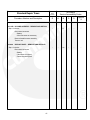
1
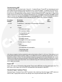
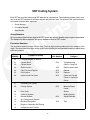
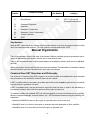
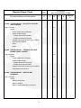
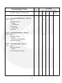
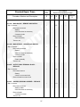
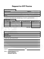
Standard Repair Times
SRT Family: CS
Portable Generator Sets
EGMBA
EGMBB
EGMBC
EGMBD
EGMBE
EGMBG
EGMBR
EGMBS
EGMBT
EGMBU
English
8-2008
900−0636 (Issue 1)
Table of Contents
Contents
Page
Foreword . . . . . . . . . . . . . . . . . . . . . . . . . . . . . . . . . . . . . . . . . . . . . . . . . . . . . . . . . .
iii
General Information . . . . . . . . . . . . . . . . . . . . . . . . . . . . . . . . . . . . . . . . . . . . . . . .
iv
Types of Standard Repair Times . . . . . . . . . . . . . . . . . . . . . . . . . . . . . . . . . . . . . . . . . . . . . . . .
Administrative SRT . . . . . . . . . . . . . . . . . . . . . . . . . . . . . . . . . . . . . . . . . . . . . . . . . . . . . . . .
Troubleshooting SRT . . . . . . . . . . . . . . . . . . . . . . . . . . . . . . . . . . . . . . . . . . . . . . . . . . . . . . .
Repair SRT . . . . . . . . . . . . . . . . . . . . . . . . . . . . . . . . . . . . . . . . . . . . . . . . . . . . . . . . . . . . . . .
Standard Repair Combined Times . . . . . . . . . . . . . . . . . . . . . . . . . . . . . . . . . . . . . . . . . . .
iv
iv
v
v
v
SRT Coding System . . . . . . . . . . . . . . . . . . . . . . . . . . . . . . . . . . . . . . . . . . . . . . . .
vi
Group Numbers . . . . . . . . . . . . . . . . . . . . . . . . . . . . . . . . . . . . . . . . . . . . . . . . . . . . . . . . . . .
Procedure Numbers . . . . . . . . . . . . . . . . . . . . . . . . . . . . . . . . . . . . . . . . . . . . . . . . . . . . . . . .
Step Numbers . . . . . . . . . . . . . . . . . . . . . . . . . . . . . . . . . . . . . . . . . . . . . . . . . . . . . . . . . . . . .
vi
vi
vii
Manual Organization . . . . . . . . . . . . . . . . . . . . . . . . . . . . . . . . . . . . . . . . . . . . . . .
vii
Cummins/Onan SRT Objectives and Philosophy . . . . . . . . . . . . . . . . . . . . . . . . . . . . . . . . . . .
How Standard Repair Times are Developed . . . . . . . . . . . . . . . . . . . . . . . . . . . . . . . . . . . . . . .
Productive Repair Time . . . . . . . . . . . . . . . . . . . . . . . . . . . . . . . . . . . . . . . . . . . . . . . . . . . . .
Time Allowances . . . . . . . . . . . . . . . . . . . . . . . . . . . . . . . . . . . . . . . . . . . . . . . . . . . . . . . . . .
Work Not Included in an SRT . . . . . . . . . . . . . . . . . . . . . . . . . . . . . . . . . . . . . . . . . . . . . . . .
Non-Productive Work . . . . . . . . . . . . . . . . . . . . . . . . . . . . . . . . . . . . . . . . . . . . . . . . . . . . . .
Service Accessibility Codes . . . . . . . . . . . . . . . . . . . . . . . . . . . . . . . . . . . . . . . . . . . . . . . . .
“A” Accessibility Rating . . . . . . . . . . . . . . . . . . . . . . . . . . . . . . . . . . . . . . . . . . . . . . . . . . . . .
“B” Accessibility Rating . . . . . . . . . . . . . . . . . . . . . . . . . . . . . . . . . . . . . . . . . . . . . . . . . . . . .
“C” Accessibility Rating . . . . . . . . . . . . . . . . . . . . . . . . . . . . . . . . . . . . . . . . . . . . . . . . . . . . .
“D” Accessibility Rating . . . . . . . . . . . . . . . . . . . . . . . . . . . . . . . . . . . . . . . . . . . . . . . . . . . . .
Standard Repair Combined Times (SRCT) . . . . . . . . . . . . . . . . . . . . . . . . . . . . . . . . . . . .
How To Use This Manual . . . . . . . . . . . . . . . . . . . . . . . . . . . . . . . . . . . . . . . . . . . . . . . . . . . . . . .
Standard Repair Times Review Procedure . . . . . . . . . . . . . . . . . . . . . . . . . . . . . . . . . . . .
Company Action . . . . . . . . . . . . . . . . . . . . . . . . . . . . . . . . . . . . . . . . . . . . . . . . . . . . . . . . . . .
vii
viii
viii
ix
ix
x
x
xi
xi
xi
xi
xi
xii
xiv
xiv
Group 00 − Complete Engine . . . . . . . . . . . . . . . . . . . . . . . . . . . . . . . . . . . . . . .
1
TROUBLESHOOT . . . . . . . . . . . . . . . . . . . . . . . . . . . . . . . . . . . . . . . . . . . . . . . . . . . . . . . . . . . .
ENGINE . . . . . . . . . . . . . . . . . . . . . . . . . . . . . . . . . . . . . . . . . . . . . . . . . . . . . . . . . . . . . . . . . . . . .
TEST . . . . . . . . . . . . . . . . . . . . . . . . . . . . . . . . . . . . . . . . . . . . . . . . . . . . . . . . . . . . . . . . . . . . . . . .
ADMINISTRATIVE TIME . . . . . . . . . . . . . . . . . . . . . . . . . . . . . . . . . . . . . . . . . . . . . . . . . . . . . . .
FAN . . . . . . . . . . . . . . . . . . . . . . . . . . . . . . . . . . . . . . . . . . . . . . . . . . . . . . . . . . . . . . . . . . . . . . . . .
AIR CLEANER ASSEMBLY . . . . . . . . . . . . . . . . . . . . . . . . . . . . . . . . . . . . . . . . . . . . . . . . . . . .
OIL . . . . . . . . . . . . . . . . . . . . . . . . . . . . . . . . . . . . . . . . . . . . . . . . . . . . . . . . . . . . . . . . . . . . . . . . . .
SPARK PLUG . . . . . . . . . . . . . . . . . . . . . . . . . . . . . . . . . . . . . . . . . . . . . . . . . . . . . . . . . . . . . . . .
AIR CLEANER ELEMENT . . . . . . . . . . . . . . . . . . . . . . . . . . . . . . . . . . . . . . . . . . . . . . . . . . . . . .
3
8
8
9
9
9
9
10
10
Group 11 − Exhaust System . . . . . . . . . . . . . . . . . . . . . . . . . . . . . . . . . . . . . . . . .
11
EXHAUST PIPE/TUBE . . . . . . . . . . . . . . . . . . . . . . . . . . . . . . . . . . . . . . . . . . . . . . . . . . . . . . . .
13
−i−
Contents
Page
Group 13 − Electrical Equipment . . . . . . . . . . . . . . . . . . . . . . . . . . . . . . . . . . . .
15
STARTER MOTOR . . . . . . . . . . . . . . . . . . . . . . . . . . . . . . . . . . . . . . . . . . . . . . . . . . . . . . . . . . . .
BATTERY CABLE . . . . . . . . . . . . . . . . . . . . . . . . . . . . . . . . . . . . . . . . . . . . . . . . . . . . . . . . . . . . .
17
17
Group 14 − Engine or Generator Set Testing . . . . . . . . . . . . . . . . . . . . . . . . .
19
TEST RUN GENERATOR . . . . . . . . . . . . . . . . . . . . . . . . . . . . . . . . . . . . . . . . . . . . . . . . . . . . . .
21
Group 16 − Mounting Adaptations . . . . . . . . . . . . . . . . . . . . . . . . . . . . . . . . . . .
23
FUEL TANK . . . . . . . . . . . . . . . . . . . . . . . . . . . . . . . . . . . . . . . . . . . . . . . . . . . . . . . . . . . . . . . . . .
25
Group 17 − Miscellaneous . . . . . . . . . . . . . . . . . . . . . . . . . . . . . . . . . . . . . . . . . .
27
MUFFLER . . . . . . . . . . . . . . . . . . . . . . . . . . . . . . . . . . . . . . . . . . . . . . . . . . . . . . . . . . . . . . . . . . .
VIBRATION ISOLATORS . . . . . . . . . . . . . . . . . . . . . . . . . . . . . . . . . . . . . . . . . . . . . . . . . . . . . .
BATTERY . . . . . . . . . . . . . . . . . . . . . . . . . . . . . . . . . . . . . . . . . . . . . . . . . . . . . . . . . . . . . . . . . . . .
29
29
29
Group 21 − Generator Equipment . . . . . . . . . . . . . . . . . . . . . . . . . . . . . . . . . . .
31
MAIN CIRCUIT BREAKER (AC) . . . . . . . . . . . . . . . . . . . . . . . . . . . . . . . . . . . . . . . . . . . . . . . .
OIL PRESSURE SENDER . . . . . . . . . . . . . . . . . . . . . . . . . . . . . . . . . . . . . . . . . . . . . . . . . . . . .
TANK LEVEL GAUGE . . . . . . . . . . . . . . . . . . . . . . . . . . . . . . . . . . . . . . . . . . . . . . . . . . . . . . . . .
33
33
33
Group 25 − Generator Components . . . . . . . . . . . . . . . . . . . . . . . . . . . . . . . . .
35
MAIN ROTOR . . . . . . . . . . . . . . . . . . . . . . . . . . . . . . . . . . . . . . . . . . . . . . . . . . . . . . . . . . . . . . . .
MAIN STATOR . . . . . . . . . . . . . . . . . . . . . . . . . . . . . . . . . . . . . . . . . . . . . . . . . . . . . . . . . . . . . . .
OUTPUT LEAD TERMINAL BLOCK . . . . . . . . . . . . . . . . . . . . . . . . . . . . . . . . . . . . . . . . . . . . .
END BELL/BEARING CARRIER . . . . . . . . . . . . . . . . . . . . . . . . . . . . . . . . . . . . . . . . . . . . . . . .
GENERATOR END ASSEMBLY COMPLETE . . . . . . . . . . . . . . . . . . . . . . . . . . . . . . . . . . . . .
37
37
37
37
38
Group 26 − Generator Control Components . . . . . . . . . . . . . . . . . . . . . . . . . .
39
DC WIRE HARNESS . . . . . . . . . . . . . . . . . . . . . . . . . . . . . . . . . . . . . . . . . . . . . . . . . . . . . . . . . .
DISPLAY PANEL . . . . . . . . . . . . . . . . . . . . . . . . . . . . . . . . . . . . . . . . . . . . . . . . . . . . . . . . . . . . . .
41
41
Index . . . . . . . . . . . . . . . . . . . . . . . . . . . . . . . . . . . . . . . . . . . . . . . . . . . . . . . . . . . . . .
43
Request for SRT Review
− ii −
Foreword
The Standard Repair Times (SRT) in this manual represent the time required to perform service repairs
on Onan Engine and Generator Sets. These times are representative of an average mechanic in a typical
dealer or distributorship using the prescribed hand tools, equipment, and all available service tools and
equipment required to perform quality repairs and do all necessary testing.
The use of this manual will:
•
Encourage uniform terminology throughout the Cummins/Onan organization
•
Standardize Repair Order job description write-ups
•
Provide shop managers with a guide for establishing flat rate quotations
•
Serve as a basis for Onan Corporation, Inc. to establish its warranty labor obligations
Reporting of errors, omissions, and recommendations for improving this publication is encouraged. Send
your suggestions or comments to:
Onan Corporation
1400 73rd Avenue NE
Minneapolis, MN 55432
Attn: Service Department
− iii −
General Information
Standard Repair Times (SRT) are lists of work tasks (procedures) and the time required to perform those
tasks. The procedures list the work tasks required to be sure an engine or generator set is ready to return
to service at the lowest possible cost to the customer. A Standard Repair Time is equitable when the repair
described in the procedure can be performed in a period of time less than or equal to the standard by a
journeyman mechanic after he/she has performed that repair on the same model, in the same application
at least once. Those SRT that a particular mechanic performs more frequently will often require less time
than the standard. Conversely, those SRT that a particular mechanic does not frequently perform may require more time than the standard. Several of the procedures may be required to accurately depict all the
work actually performed to return a particular engine or generator set to service because the repair of a
particular engine or generator set is often unique in light of the complaint, failure model, progressive damage, condition of the parts and customer desires. To allow for differences in the time required to perform
a repair because of interference by the application, a Service Accessibility Code Scheme has been created.
Types of Standard Repair Times
There are three types of SRT. Most often at least one of each type is necessary to accurately depict the
repair. The three types are:
•
Administrative
•
Troubleshooting
•
Repair
Administrative SRT
Administrative SRT are intended to provide time to move the vehicle engine or generator set to and from
the work area, fill out the repair order, record SRT used, etc. It is intended that an administrative SRT be
used only once for each repair order. There are two administrative SRT found in this manual in Group 00
− Complete Engine. One of the administrative SRT is to be used when the repair takes place in a shop operated by the repairing location. The other administrative SRT is to be used when the repair takes place away
from the shop operated by the repairing location (road repairs). The time for the road repair administrative
SRT is greater to allow for loading and unloading tools, equipment, parts, etc. from the service truck.
− iv −
Troubleshooting SRT
Troubleshooting SRT are found only in Group 00 − Complete Engine. These SRT are intended to be used
when diagnosing and analyzing engine, generator set or component failures. Troubleshooting SRT are broken down in to logical numbered steps. The time for each step is cumulative with successive steps, including the time for the appropriate preceding step(s). Some troubleshooting SRT contain time to remove and
install components to perform the check(s) listed. Most do not. If a troubleshooting SRT does NOT include
required component removal and installation, it is intended that the SRT for the removal and installation
of that component be in addition to the troubleshooting SRT. Refer to the following example:
Procedure
Number
00−055
Procedure
Description
SRT
Hours
Troubleshoot − Lubricating Oil Consumption Excessive
Includes:
−01
− Check:
0.4
− Oil consumption report
− For external oil leaks
− For overfilled oil pan
− Oil specifications
− For fuel contamination
− Oil change interval
− For engine oil in torque converter
−02
− Perform checks in Step 01
1.0
− Check:
− Oil temperature
− Air compressor oil consumption
− Turbocharger seal
− Crankcase blowby
In the above example, the time required to perform the checks in Step 01 is 0.4 hour. If the problem is not
located while performing the checks in Step 01, an additional 0.6 hour is allowed to perform the checks in
Step 02 for a total of 1.0 hour. The total troubleshooting time appropriate is the time indicated in the column
directly in line with the final step required to locate the problem. The step required to locate the problem
may or may not be the last step shown in the troubleshooting SRT. Each step contains information as to
which steps are included.
Repair SRT
Repair SRT make up the majority of this manual. These are the SRT that cover the actual repair work. The
time shown on the same line as the SRT code and title is the total time for that SRT.
Standard Repair Combined Times
Standard Repair Combined Times (SRCT) provide for the combining of the three types of SRT under one
code so that, if appropriate, the user can identify the work performed with fewer SRT codes.
−v−
SRT Coding System
Each SRT has a unique code so that SRT data can be computerized. The numbering system used is common to all the SRT manuals for all Onan engines and generator sets. The portion of the system shown in
the manual contains three segments:
•
Group Number
•
Procedure Number
•
Step Number
Group Numbers
Group numbers (the first two digits in the SRT code) are used to identify major engine components.
The sample list below explains the group numbers used in SRT charts.
Procedure Numbers
The procedure number consists of three digits. The first digit provides guidance as to the category of the
repair. The second and third digits, shown as XX in the following list, are sequential numbers or alpha letters
within the category.
Group
Number
Specific Repair Number
Contents of Group
Description of
Category
00
Complete Engine or Genset
01
Cylinder Block
02
Cylinder Head
03
Rocker Levers
1XX
Remove and Install
04
Cam Followers/Tappets
2XX
Rebuild
05
Fuel System
3XX
Replace
06
Injectors and Fuel Lines
4XX
Clean and Visually
0XX
Troubleshooting
ONLY in Group 00
Check or Inspect for
Reuse
07
Lubricating Oil System
08
Cooling System
5XX
Machine/Ream/
Dowel/
09
Drive Units
Sleeve
10
Intake Air System
Modify/Cut/Lap
11
Exhaust System
12
Air (Compressed) System
13
Electrical Equipment
14
Engine or Generator Set Testing
15
Instruments and Controls
− vi −
6XX
Adjust/Calibrate
7XX
Test
Group
Number
Specific Repair Number
Contents of Group
16
Mounting Adaptations
17
Miscellaneous
21
Generator Equipment
22
Hardware
25
Generator Components
26
Generator Control Components
27
Transfer Switches
99
SRCT
9XX
Description of
Category
(SRCT in Group 99)
General/Miscellaneous
Step Numbers
While all SRT codes will contain a Group and Procedure number, only those procedures that are broken
down into steps have step numbers. The step numbers are sequential within a SRT.
Manual Organization
There is an alphabetic index in the back of the manual. Within a particular group the procedures are arranged in alphabetical order by title, thus are not in code numeric order.
There is also a numerical index in which the procedures are arranged in numeric order and not in alphabetical order.
Within a procedure, the user will note that some lines are indented. This indentation is intended to indicate
that the sub-tasks are part of the task under which they are indented.
Cummins/Onan SRT Objectives and Philosophy
The objective of Cummins/Onan SRT program is to provide credible and equitable labor time standards
and procedures to the worldwide Cummins/Onan service network.
A SRT is credible when the procedure accurately depicts the work that must be performed to accomplish
a quality engine or generator set repair.
A SRT is equitable when it can be performed in a period of time less than or equal to the standard by a
journeyman mechanic after he/she has performed that repair at least once.
To establish credible and equitable SRT with sufficient flexibility to account for differences in complaints,
failures, progressive damage, customer desires, etc., SRT have been structured using the following considerations:
− What must ALWAYS be done to the engine or generator set to perform the work.
− What MAY have to be done to the engine or generator set parts dependent on their condition.
− What MAY have to be removed to access the engine or generator set.
− vii −
− How difficult it is for the mechanic to reach the engine or generator set even after the interfering application hardware has been removed.
While the most frequent use of SRT information is the Onan Warranty System, it is Onan’s intent that the
SRT be applicable to repairs conducted for any customer.
As SRT’s are developed, it is assumed:
− That all the required tools, equipment, and supplies are available in sufficient quantity and in operating
condition.
− That required Onan Service Manuals are available to the mechanic are being used.
− That the correct parts are available when the mechanic needs them.
How Standard Repair Times are Developed
SRT’s are developed from time studies conducted in the field and Onan Technical Service Personnel. Technical Service Representatives create a comprehensive list of all the work elements or tasks required to perform specific repairs. Field studies are analyzed to find these same work elements or tasks and determine
the time required for each. The time for work elements or tasks that are not included in the field time studies
is determined by conducting free engine or generator set studies or by estimation using similar elements
from existing time studies. A time is determined for each element of the procedure. The time for all elements
is then totaled to establish the total productive repair time.
Productive Repair Time
Productive Repair Time is described as the actual time involved doing productive work, such as: removing,
disassembling, cleaning, inspecting, machining, installing and adjusting parts or components. In addition,
the following operations are considered to be productive work for inclusion in a SRT:
− Clock on and off the job or repair order, including shift changes.
− Move vehicle, engine or generator set to and from the work area.
− Move tool box to the work area.
− Obtain tools from tool box, wipe and put away after use.
− Refer to service manuals.
− Obtain, unpack and clean replacement parts as necessary.
− Package and mark parts removed as necessary for warranty or local consumer laws.
− Operate engine or generator set to check for proper operation.
− Clean work area at completion of shift or repair.
− Properly dispose of used engine fluids such as oil and coolant.
− Write summary of work performed at completion of repair or work shift.
− Help from another mechanic (time for one man to complete the task times two).
− viii −
Time Allowances
After the total productive time is established, an additional allowance of 15 percent is added to cover the
following:
− Personal time of 5 percent for:
− Scheduled rest breaks
− Personal phone calls
− Restroom breaks
− Shift changes
− Supplementary time of 10 percent to cover normal work interruptions:
− Seized or hard turning fasteners
− Extra time for extremely dirty equipment
− Excessive waiting time for replacement parts
− Brief assistance to other mechanics (less than 5 minutes)
− Routine maintenance (not repair) of shop equipment
− Obtain consumable supplies
− Technical consultation with shop supervision
The following is an example of how the allowances are calculated to establish the SRT for a procedure
where the productive time is 208.7 minute (3.48 hr):
Allowance
Type
Productive Repair Time
Allowance
Percent (%)
Time
(Minutes)
100
208.7
5
10.4
Supplementary
10
20.9
TOTAL
115
240.0
Personal
Published Standard Repair Time = 4.0 hours
Work Not Included in an SRT
For almost every complete repair there will be one SRT that contains most of the work performed. This is
sometimes called a base repair. For example, repairing an engine for high oil consumption often requires
use of the SRT title Piston and Rings − Remove and Install. This SRT contains most of the time appropriate
for the repair, so it is the base repair. There can be work required that is not part of this base SRT. This does
not mean that the other work is non−productive, rather that other work is NOT required EVERY TIME the
pistons and rings are removed and installed. More often than not, this other work is covered by another SRT.
If the other work is not included in the base repair or in another SRT, the work is probably still productive
work required for that particular repair.
− ix −
Non-Productive Work
Analysis of past SRT time studies reveals the following general types of work that were not considered to
be productive:
− Waiting on camshaft gears to heat and cool
− Waiting on another mechanic to finish using special tools or shop equipment
− Hunting for misplaced parts
− Repairing shop equipment
− Sorting through capscrews, to find the correct length, that were all thrown together into one basket during disassembly
− Repairing customer supplied components
− Salvaging parts or tools that have been damaged from improper handling or lack of correct tools
− Clearing off tables, parts carts, parts racks etc. left dirty or loaded with parts from previous
repairs on other equipment
− Rework caused by installation of incorrect parts or incorrect installation of correct parts
− Fabrication or modification of special tools or equipment because the correct tools or equipment are not
available
− Visiting during non−break time
− Conducting business with tool vendors
− Waiting on other mechanics to provide required help
− Waiting on parts clerk to fill orders for other mechanics
− Unnecessary inspection of new parts
− “Hot Setting” valves and injectors when not required
− Repairs to application hardware
− Rework resulting from failure to follow recommended service practices
− Performing work that is not part of the repair order or helping another mechanic
Service Accessibility Codes
Service repairs are affected by engine or generator set accessibility. The more difficult the accessibility, the
longer it will take to complete the tasks given in the SRT procedure. Accessibility for a particular application
is determined by reviewing the application and rating the degree of difficulty for performing the 20 most
common repairs. Four codes (A, B, C and D) are used to classify the degree of difficulty for the service accessibility of a specific model or type of equipment. An “A” accessibility code indicates the engine or generator set is easily accessible. A “D” code indicates the application does not make the engine or generator set
as easily accessible, thus the highest degree of difficulty relative to SRT standards. A “S” code is included
for special or specific repairs not covered in the other four classifications. The “R” code indicates the repair
is completed with the component, engine or generator set removed from the application.
−x−
“A” Accessibility Rating
1. Engine or generator sets mounted in equipment where 90 percent of the work can be performed
while standing on the ground, shop floor, or flat work deck.
2. Engine or generator set can be accessed without removing any doors or panels.
3. Interfering application hardware can all be removed.
4. Clearance is sufficient for hands, wrenches, and drain and fill operations, making visual checks
and room to stand and work.
“B” Accessibility Rating
1. ]Engine or generator set mounted in equipment where 70 percent of the work can be performed
while standing on the ground, shop floor or flat work deck.
2. Access to the engine can be gained by removing access panels or doors.
3. On 80 percent of the operations, interfering application hardware can be removed.
4. On 80 percent of the operations, clearance is sufficient for hands, wrenches, service tools, drain
and fill operations, making visual checks and room to stand and work.
“C” Accessibility Rating
1. Engine or generator set mounted in equipment where 50 percent of the work can be performed
while standing on the ground, shop floor or flat work deck.
2. Access to the engine or generator set can be gained by removing the hood, structural members
(bolted in) or sheet metal panels.
3. On 60 percent of the operations, interfering application hardware can be removed.
4. On 60 percent of the operations, clearance is sufficient for hands, wrenches, service tools, drain
and fill operations, making visual checks and room to stand and work.
“D” Accessibility Rating
1. Engine or generator set mounted in equipment where 25 percent of the work can be performed
while standing on the ground, shop floor or flat work deck.
2. Access to the engine or generator set is limited due to interference from permanently mounted
structural members, sheet metal or crossmembers.
3. On 40 percent of the operations, clearance is sufficient for hands, wrenches, service tools, drain
and fill operations, making visual checks and limited room to stand and work.
Standard Repair Combined Times (SRCT)
SRCT’s are the combination of some of the SRT’s in the manual within a distinctive code. These SRCT’s
are based on field input of SRT that are most frequently used in combination to describe the most common
field repairs on this engine.
Use of SRCT’s can reduce the amount of time required to determine the labor standard for a specific complete engine or generator set repair. The use of SRCT will also reduce the number of codes required when
completing a warranty claim or customer invoice.
SRCT’s are intended to supplement, NOT replace, SRT. One SRCT code can be used instead of several
SRT codes.
− xi −
It is intended that other appropriate SRT can be used to supplement a SRCT as long as the work does not
overlap. If there is overlapping work, do not use a SRCT.
How To Use This Manual
1. Determine the actual work performed:
− Obtain this information from the work description on the repair order.
2. Determine the Accessibility Code:
− Determine the application from the repair order.
− Look in the “Accessibility Code Listing” on page to determine the accessibility code for the application
involved in the repair. If the application is not shown, assume the accessibility code is “B”.
− Write down the code.
3. Determine applicable SRCT:
− Find the Contents Page for Group 99 − Standard Repair Combined Times.
− Compare the titles to the work performed to determine if a SRCT will apply.
− If there is a SRCT that seems to apply, find that SRCT and compare the SRT within the SRCT to the
work performed. If you are not sure of the work included in the SRT, read that SRT and compare the
procedure listing with the work performed.
− If a SRCT applies to all or part of the work performed, find the column that contains the same accessibility code determined in Step 2 above.
− Move down the column to the line containing the SRCT code and title and pick out the appropriate
time.
− If all the work in the SRCT is performed and additional steps were taken, use the SRCT and continue
to Step 4 to cover the additional work.
− If there is NOT an appropriate SRCT, move to Step 4.
4. Determine the appropriate repair SRT:
− Use the information from the repair order to identify the parts involved.
− Use the contents page at the front of the manual or the alphabetical index in the back of the manual
to determine the appropriate SRT group for the parts and/or work involved.
− Find the contents page for that group.
− Read the contents page for procedure titles that seem to correspond to the work performed.
− Find the SRT within the group.
− Read the SRT procedure listing to determine the work included.
− If the work performed and the work included in the SRT are the same, all or in part, determine and
record the time.
− xii −
− Repeat the steps in this paragraph until you have determined a SRT for all the work performed.
5. Determine the appropriate troubleshooting SRT:
− Read the repair order to determine what troubleshooting work was performed.
− Find the contents page for Group 00.
− Read the contents page for procedure to determine the work included in each step.
− If the work performed and the work included in the troubleshooting SRT are the same, all or in part,
determine and record the time of the SRT step. Remember that troubleshooting SRT are cumulative.
6. Determine the appropriate miscellaneous SRT:
− Read the repair order to determine if any application hardware was removed and installed in order
to access the engine or generator set.
− Find the contents page for Group 17.
− Read the contents page for procedure titles that seem to correspond to the work performed.
− Find the SRT within the group.
− Read the SRT procedure to determine the work included in the SRT.
− If the work performed and the work included in the SRT are the same, all or in part, determine and
record the time.
− If the work required to application hardware is not given in the SRT manual, determine the time for
ONLY this work from the repair order. Record the time for possible use as “99−999” or “Non−SRT
Time”.
7. Determine the appropriate administrative SRT:
− Both of the administrative SRT are shown at the beginning of Group 00.
− Determine the appropriate SRT.
− Record the time.
8. Determine the total appropriate SRT time:
− Check to be sure that there is no duplication of tasks within the SRT procedures selected. If there
is work duplicated by some of those selected, use other information contained in the manual to reduce the time of one of the SRT accordingly. If the information is not available, make an estimate.
− Total all the times obtained during performance of Steps 2 through 7.
− xiii −
Standard Repair Times Review Procedure
Onan Corporation makes every effort to be sure the SRT published in this manual are credible and equitable. It will be necessary to review the published times when one or more of the following changes occur:
− Design changes to special service tools or equipment required to perform the repair
− Changes to the repair procedure
A formal SRT review procedure is available for any Cummins/Onan Authorized Repair Location that believes the SRT shown in this manual are incorrect.
To be sure prompt attention and an accurate appraisal is given to your request, the following guidelines
must be met:
1. Be sure the technician has followed all the procedures and used all the service tools referred to in
the appropriate service manuals.
2. Be sure a journeyman technician performed the repair, one who has completed the repair a sufficient number of times to become familiar with the procedure.
3. Be sure all the SRT, including supplemental SRT, appropriate for the repair are being used.
4. Include as much detail as possible about the specific repair.
NOTE: It is NOT the intent of this procedure to provide a forum for appealing or disputing the amount of
time or the SRT judged appropriate on a particular warranty claim. Communication of this sort must follow
the processes shown in the Onan Warranty Administration Manual.
5. Provide photographs of the installation.
6. Provide copies of all repair orders applicable to the SRT involved, the technicians time cards, and
any other information related to the repair that will aid in the review process.
7. Be sure to provide the correct name of the repairing location, a phone number, and point of contact.
Company Action
Upon receipt of the request for an SRT review, the following action will be taken:
1. The person signing the request will be contacted to acknowledge the receipt of the request.
2. All the information provided will be analyzed and compared with the history files of the specific operation.
3. All information will be analyzed to determine if an error has been made in the procedure, the operations description, or the published repair time.
4. If it is determined the published repair time is incorrect, additional studies/analysis will be performed to establish the correct time. The requester will be notified of the results, and the results will
be published in the next SRT update.
5. If it is determined that the time and procedure is correct, recommendations and assistance will be
offered as needed.
− xiv −
Group 00 − Complete Engine
Contents
Page
TROUBLESHOOT . . . . . . . . . . . . . . . . . . . . . . . . . . . . . . . . . . . . . . . . . . . . . . . . . . . . . . . . . . . . . . . . .
3
ENGINE CRANKS BUT WILL NOT START . . . . . . . . . . . . . . . . . . . . . . . . . . . . . . . . . . . . . . . . . . . . . . . . . . . . . . . .
ENGINE DIFFICULT TO START . . . . . . . . . . . . . . . . . . . . . . . . . . . . . . . . . . . . . . . . . . . . . . . . . . . . . . . . . . . . . . . . . .
ENGINE NOISE EXCESSIVE . . . . . . . . . . . . . . . . . . . . . . . . . . . . . . . . . . . . . . . . . . . . . . . . . . . . . . . . . . . . . . . . . . . .
ENGINE POWER OUTPUT LOW . . . . . . . . . . . . . . . . . . . . . . . . . . . . . . . . . . . . . . . . . . . . . . . . . . . . . . . . . . . . . . . . .
ENGINE STARTS BUT WILL NOT KEEP RUNNING . . . . . . . . . . . . . . . . . . . . . . . . . . . . . . . . . . . . . . . . . . . . . . . .
ENGINE UNSTABLE (HUNTS) (GENSET) . . . . . . . . . . . . . . . . . . . . . . . . . . . . . . . . . . . . . . . . . . . . . . . . . . . . . . . . .
VIBRATION EXCESSIVE . . . . . . . . . . . . . . . . . . . . . . . . . . . . . . . . . . . . . . . . . . . . . . . . . . . . . . . . . . . . . . . . . . . . . . . .
ENGINE WILL NOT CRANK OR CRANKS SLOWLY . . . . . . . . . . . . . . . . . . . . . . . . . . . . . . . . . . . . . . . . . . . . . . . .
ENGINE WILL NOT SHUT OFF . . . . . . . . . . . . . . . . . . . . . . . . . . . . . . . . . . . . . . . . . . . . . . . . . . . . . . . . . . . . . . . . . .
HIGH/LOW AC OUTPUT (GENSET) . . . . . . . . . . . . . . . . . . . . . . . . . . . . . . . . . . . . . . . . . . . . . . . . . . . . . . . . . . . . . .
NO OUTPUT VOLTAGE (AVR) (GENSET) . . . . . . . . . . . . . . . . . . . . . . . . . . . . . . . . . . . . . . . . . . . . . . . . . . . . . . . . .
UNSTABLE VOLTAGE, ENGINE STABLE (GENSET) . . . . . . . . . . . . . . . . . . . . . . . . . . . . . . . . . . . . . . . . . . . . . . .
BATTERY NOT CHARGING . . . . . . . . . . . . . . . . . . . . . . . . . . . . . . . . . . . . . . . . . . . . . . . . . . . . . . . . . . . . . . . . . . . . .
CIRCUIT BREAKER (AC MAIN) TRIPS . . . . . . . . . . . . . . . . . . . . . . . . . . . . . . . . . . . . . . . . . . . . . . . . . . . . . . . . . . . .
NO PROBLEM FOUND . . . . . . . . . . . . . . . . . . . . . . . . . . . . . . . . . . . . . . . . . . . . . . . . . . . . . . . . . . . . . . . . . . . . . . . . .
EXCESSIVE OIL CONSUMPTION . . . . . . . . . . . . . . . . . . . . . . . . . . . . . . . . . . . . . . . . . . . . . . . . . . . . . . . . . . . . . . . .
OIL LEAK . . . . . . . . . . . . . . . . . . . . . . . . . . . . . . . . . . . . . . . . . . . . . . . . . . . . . . . . . . . . . . . . . . . . . . . . . . . . . . . . . . . . . .
BELOW NOMINAL FREQUENCY . . . . . . . . . . . . . . . . . . . . . . . . . . . . . . . . . . . . . . . . . . . . . . . . . . . . . . . . . . . . . . . .
3
3
3
4
4
4
4
5
5
5
6
6
6
7
7
7
7
8
ENGINE . . . . . . . . . . . . . . . . . . . . . . . . . . . . . . . . . . . . . . . . . . . . . . . . . . . . . . . . . . . . . . . . . . . . . . . . . .
8
REPLACE . . . . . . . . . . . . . . . . . . . . . . . . . . . . . . . . . . . . . . . . . . . . . . . . . . . . . . . . . . . . . . . . . . . . . . . . . . . . . . . . . . . . .
8
TEST . . . . . . . . . . . . . . . . . . . . . . . . . . . . . . . . . . . . . . . . . . . . . . . . . . . . . . . . . . . . . . . . . . . . . . . . . . . . .
8
STATOR WINDINGS . . . . . . . . . . . . . . . . . . . . . . . . . . . . . . . . . . . . . . . . . . . . . . . . . . . . . . . . . . . . . . . . . . . . . . . . . . . .
ROTOR WINDINGS . . . . . . . . . . . . . . . . . . . . . . . . . . . . . . . . . . . . . . . . . . . . . . . . . . . . . . . . . . . . . . . . . . . . . . . . . . . .
8
8
ADMINISTRATIVE TIME . . . . . . . . . . . . . . . . . . . . . . . . . . . . . . . . . . . . . . . . . . . . . . . . . . . . . . . . . . . .
9
OPEN/CLOSE REPAIR ORDER (SHOP) . . . . . . . . . . . . . . . . . . . . . . . . . . . . . . . . . . . . . . . . . . . . . . . . . . . . . . . . . .
9
FAN . . . . . . . . . . . . . . . . . . . . . . . . . . . . . . . . . . . . . . . . . . . . . . . . . . . . . . . . . . . . . . . . . . . . . . . . . . . . . .
9
REPLACE ALL . . . . . . . . . . . . . . . . . . . . . . . . . . . . . . . . . . . . . . . . . . . . . . . . . . . . . . . . . . . . . . . . . . . . . . . . . . . . . . . . .
9
AIR CLEANER ASSEMBLY . . . . . . . . . . . . . . . . . . . . . . . . . . . . . . . . . . . . . . . . . . . . . . . . . . . . . . . . .
9
REMOVE AND INSTALL . . . . . . . . . . . . . . . . . . . . . . . . . . . . . . . . . . . . . . . . . . . . . . . . . . . . . . . . . . . . . . . . . . . . . . . .
9
OIL . . . . . . . . . . . . . . . . . . . . . . . . . . . . . . . . . . . . . . . . . . . . . . . . . . . . . . . . . . . . . . . . . . . . . . . . . . . . . . .
9
DRAIN/FILL . . . . . . . . . . . . . . . . . . . . . . . . . . . . . . . . . . . . . . . . . . . . . . . . . . . . . . . . . . . . . . . . . . . . . . . . . . . . . . . . . . . .
9
SPARK PLUG . . . . . . . . . . . . . . . . . . . . . . . . . . . . . . . . . . . . . . . . . . . . . . . . . . . . . . . . . . . . . . . . . . . . .
10
CHANGE . . . . . . . . . . . . . . . . . . . . . . . . . . . . . . . . . . . . . . . . . . . . . . . . . . . . . . . . . . . . . . . . . . . . . . . . . . . . . . . . . . . . . .
10
AIR CLEANER ELEMENT . . . . . . . . . . . . . . . . . . . . . . . . . . . . . . . . . . . . . . . . . . . . . . . . . . . . . . . . . .
10
REPLACE . . . . . . . . . . . . . . . . . . . . . . . . . . . . . . . . . . . . . . . . . . . . . . . . . . . . . . . . . . . . . . . . . . . . . . . . . . . . . . . . . . . . .
10
1
This Page Intentionally Left Blank
2
00−021
In-Chassis
Service Accessibility Codes
Standard Repair Times
Removed
From
Chassis
Procedure Number and Description
R
A
B
C
D
Special
S
−
−
0.3
−
−
−
−
−
0.3
−
−
−
−
−
0.3
−
−
−
TROUBLESHOOT − ENGINE CRANKS BUT
WILL NOT START
Step 1 Includes:
Check for:
− Fuel in tank
− Spark
− Spark plug gap
− Valve lash
− Compression
− Spark arrestor
00−024
TROUBLESHOOT − ENGINE DIFFICULT TO
START
Step 1 Includes:
Check:
− Fuel supply
− Binding throttle linkage
− Choke operation
− Spark plug/plug gap
− Compression
− Spark arrestor
00−027
TROUBLESHOOT − ENGINE NOISE
EXCESSIVE
Step 1 Includes:
Check:
− Visually check for physical damage
− Fan guard/fan interference
− For rubbing components
− For loose components
3
00−031
In-Chassis
Service Accessibility Codes
Standard Repair Times
Removed
From
Chassis
Procedure Number and Description
R
A
B
C
D
Special
S
−
−
0.3
−
−
−
−
−
0.3
−
−
−
−
−
0.3
−
−
−
−
−
0.3
−
−
−
TROUBLESHOOT − ENGINE POWER OUTPUT
LOW
Step 1 Includes:
Check:
− Throttle linkage travel
− Intake and exhaust pipe restriction
− Spark arrestor clean out
− For intake leaks
− Fuel line condition
00−037
TROUBLESHOOT − ENGINE STARTS BUT
WILL NOT KEEP RUNNING
Step 1 Includes:
Check for:
− Fuel level
− Fuel contamination
− Damaged fuel line
− Intake or exhaust restriction
00−041
TROUBLESHOOT − ENGINE UNSTABLE
(HUNTS) (GENSET)
Step 1 Includes:
Check:
− Fuel supply
− Governor spring
− Binding throttle linkage
− Intake leaks
00−042
TROUBLESHOOT − VIBRATION EXCESSIVE
Step 1 Includes:
Check:
− Fan
− Engine mounts
− Loose parts
4
00−044
In-Chassis
Service Accessibility Codes
Standard Repair Times
Removed
From
Chassis
Procedure Number and Description
R
A
B
C
D
Special
S
−
−
0.3
−
−
−
−
−
0.2
−
−
−
−
−
0.5
−
−
−
TROUBLESHOOT − ENGINE WILL NOT
CRANK OR CRANKS SLOWLY
Step 1 Includes:
Check for:
− Battery condition
− Battery connections
− Voltage at starter during cranking
− Engine/AC alternator seizure
00−045
TROUBLESHOOT − ENGINE WILL NOT SHUT
OFF
Step 1 Includes:
Check for:
− Start/Stop switch
− Ground connections
00−0AD TROUBLESHOOT − HIGH/LOW AC OUTPUT
(GENSET)
Step 1 Includes:
Check:
− Proper output lead configuration
− Genset output voltage:
− Voltage at line side of breaker
− Voltage at load side of breaker
− Voltage sense leads secure/in good condition
− Wire harness condition
− Rotor status checks
5
In-Chassis
Service Accessibility Codes
Standard Repair Times
Removed
From
Chassis
Procedure Number and Description
R
A
B
C
D
Special
S
−
−
0.5
−
−
−
−
−
0.5
−
−
−
−
−
0.5
−
−
−
00−0AG TROUBLESHOOT − NO OUTPUT VOLTAGE
(AVR) (GENSET)
Step 1 Includes:
Check:
− Proper output lead configuration
− Genset output voltage:
− Voltage at line side of breaker
− Voltage at load side of breaker
− Voltage sense leads secure/in good condition
− Wire harness condition
− Rotor
− Stator
00−0AH TROUBLESHOOT − UNSTABLE VOLTAGE,
ENGINE STABLE (GENSET)
Step 1 Includes:
Check:
− Proper output lead connection
− Genset output voltage:
− Voltage at load side of breaker
− Voltage at line side of breaker
− Voltage sense leads secure/in good condition
− Plugs/harness connections
00−0AS
TROUBLESHOOT − BATTERY NOT
CHARGING
Step 1 Includes:
Check:
− Battery connections
− Battery condition
− Battery charging alternator connections
6
In-Chassis
Service Accessibility Codes
Standard Repair Times
Removed
From
Chassis
Procedure Number and Description
R
A
B
C
D
Special
S
−
−
0.4
−
−
−
−
−
0.5
−
−
−
−
−
0.6
−
−
−
−
−
0.3
−
−
−
00−0DA TROUBLESHOOT − CIRCUIT BREAKER (AC
MAIN) TRIPS
Step 1 Includes:
Check:
− Overload condition
− Short on customer loads
− Correct genset output voltage
00−0DC TROUBLESHOOT − NO PROBLEM FOUND
Step 1 Includes:
Inspect genset
Attempt to validate customer complaint
00−0DF
TROUBLESHOOT − EXCESSIVE OIL
CONSUMPTION
Step 1 Includes:
Check:
− Engine oil level
− External leaks
− Proper oil specifications
− Fuel contamination
− Oil change intervals
− Compression
− Valves
00−0DG TROUBLESHOOT − OIL LEAK
Step 1 Includes:
Check:
− Engine oil level
− Visual inspection
− Oil dye
7
00−0DJ
In-Chassis
Service Accessibility Codes
Standard Repair Times
Removed
From
Chassis
Procedure Number and Description
R
A
B
C
D
Special
S
−
−
0.4
−
−
−
−
−
2.0
−
−
−
−
−
0.3
−
−
−
−
−
0.3
−
−
−
TROUBLESHOOT − BELOW NOMINAL
FREQUENCY
Step 1 Includes:
Check:
− Verify speed
− Governor settings
− Fuel system
00−3AA ENGINE − REPLACE
Step 1 Includes:
Engine oil drain and refill
Remove and install:
− Alternator
− Wiring harness
− Fuel lines
− Exhaust system
− Engine
00−7AB TEST − STATOR WINDINGS
Step 1 Includes:
Isolate stator windings
Check for shorted windings
Measure winding resistance
Reconnect stator leads to block
00−7AC TEST − ROTOR WINDINGS
Step 1 Includes:
Visual inspection
Disconnect/reconnect main rotor lead(s)
Check for shorts
Measure winding resistance
8
00−901
In-Chassis
Service Accessibility Codes
Standard Repair Times
Removed
From
Chassis
Procedure Number and Description
R
A
B
C
D
Special
S
0.4
−
−
−
−
−
−
−
0.7
−
−
−
−
−
0.1
−
−
−
−
−
0.2
−
−
−
ADMINISTRATIVE TIME − OPEN/CLOSE
REPAIR ORDER (SHOP)
Step 1 Includes:
Clock on and off the job
Move equipment to and from work area
Record the following:
− Generator set model number
− Generator set serial number
− Engine serial number
− Hours of operation
− Date in service
Load/unload tools, equipment, and repair parts
Clean up work area
Write repair order
Write repair procedures
08−318
FAN − REPLACE ALL
Step 1 Includes:
Disconnect/reconnect:
− Battery
− Wire harnesses as necessary
Remove/install:
− Fan guards
− Fan assembly
Test run unit
10−117
AIR CLEANER ASSEMBLY − REMOVE AND
INSTALL
Step 1 Includes:
Disconnect/reconnect:
− Battery
− Harnesses as necessary
Remove/install air cleaner assembly
07−801
OIL − DRAIN/FILL
Step 1 Includes:
Drain and fill oil
9
13−109
In-Chassis
Service Accessibility Codes
Standard Repair Times
Removed
From
Chassis
Procedure Number and Description
R
A
B
C
D
Special
S
−
−
0.1
−
−
−
−
−
0.1
−
−
−
SPARK PLUG − CHANGE
Step 1 Includes:
Remove and replace spark plug
10−301
AIR CLEANER ELEMENT − REPLACE
Step 1 Includes:
Remove/install:
− Air cleaner element
10
Group 11 − Exhaust System
Contents
Page
EXHAUST PIPE/TUBE . . . . . . . . . . . . . . . . . . . . . . . . . . . . . . . . . . . . . . . . . . . . . . . . . . . . . . . . . . . . .
13
REPLACE . . . . . . . . . . . . . . . . . . . . . . . . . . . . . . . . . . . . . . . . . . . . . . . . . . . . . . . . . . . . . . . . . . . . . . . . . . . . . . . . . . . . .
13
11
This Page Intentionally Left Blank
12
11−3AB
Standard Repair Times
Removed
From
Chassis
Procedure Number and Description
R
In-Chassis
Service Accessibility Codes
A
B
EXHAUST PIPE/TUBE − REPLACE
Step 1 Includes:
0.3
Disconnect/reconnect battery
Remove/install exhaust pipe
13
C
D
Special
S
Standard Repair Times
Removed
From
Chassis
Procedure Number and Description
R
In-Chassis
Service Accessibility Codes
A
This Page Intentionally Left Blank
14
B
C
D
Special
S
Group 13 − Electrical Equipment
Contents
Page
STARTER MOTOR . . . . . . . . . . . . . . . . . . . . . . . . . . . . . . . . . . . . . . . . . . . . . . . . . . . . . . . . . . . . . . . . .
17
REMOVE AND INSTALL . . . . . . . . . . . . . . . . . . . . . . . . . . . . . . . . . . . . . . . . . . . . . . . . . . . . . . . . . . . . . . . . . . . . . . . .
17
BATTERY CABLE . . . . . . . . . . . . . . . . . . . . . . . . . . . . . . . . . . . . . . . . . . . . . . . . . . . . . . . . . . . . . . . . .
17
REPLACE . . . . . . . . . . . . . . . . . . . . . . . . . . . . . . . . . . . . . . . . . . . . . . . . . . . . . . . . . . . . . . . . . . . . . . . . . . . . . . . . . . . . .
17
15
This Page Intentionally Left Blank
16
13−104
In-Chassis
Service Accessibility Codes
Standard Repair Times
Removed
From
Chassis
Procedure Number and Description
R
A
B
C
D
Special
S
−
−
0.5
−
−
−
−
−
0.1
−
−
−
STARTER MOTOR − REMOVE AND INSTALL
Step 1 Includes:
Disconnect/reconnect:
− Battery
− Wire harnesses as necessary
− Battery leads
Remove and install starter
Test run unit
13−3AP
BATTERY CABLE − REPLACE
Step 1 Includes:
Remove/replace battery cable (each)
17
Standard Repair Times
Removed
From
Chassis
Procedure Number and Description
R
In-Chassis
Service Accessibility Codes
A
This Page Intentionally Left Blank
18
B
C
D
Special
S
Group 14 − Engine or Generator Set Testing
Contents
Page
TEST RUN GENERATOR . . . . . . . . . . . . . . . . . . . . . . . . . . . . . . . . . . . . . . . . . . . . . . . . . . . . . . . . . . .
19
83
This Page Intentionally Left Blank
20
14−704
In-Chassis
Service Accessibility Codes
Standard Repair Times
Removed
From
Chassis
Procedure Number and Description
R
A
B
C
D
Special
S
−
−
0.2
−
−
−
TEST RUN GENERATOR
Step 1 Includes:
Disconnect/reconnect:
− Load bank
− Fuel supply
− Battery
Start and operate set:
− No load
− Full load
Check voltage and frequency
Inspect for fluid leaks
21
Standard Repair Times
Removed
From
Chassis
Procedure Number and Description
R
In-Chassis
Service Accessibility Codes
A
This Page Intentionally Left Blank
22
B
C
D
Special
S
Group 16 − Mounting Adaptations
Contents
Page
FUEL TANK . . . . . . . . . . . . . . . . . . . . . . . . . . . . . . . . . . . . . . . . . . . . . . . . . . . . . . . . . . . . . . . . . . . . . . .
25
REMOVE AND INSTALL . . . . . . . . . . . . . . . . . . . . . . . . . . . . . . . . . . . . . . . . . . . . . . . . . . . . . . . . . . . . . . . . . . . . . . . .
25
23
This Page Intentionally Left Blank
24
16−1AI
In-Chassis
Service Accessibility Codes
Standard Repair Times
Removed
From
Chassis
Procedure Number and Description
R
A
B
C
D
Special
S
−
−
0.4
−
−
−
FUEL TANK − REMOVE AND INSTALL
Step 1 Includes:
Disconnect/reconnect:
− Battery
− Fuel connections
− Drain/refill fluids
25
Standard Repair Times
Removed
From
Chassis
Procedure Number and Description
R
In-Chassis
Service Accessibility Codes
A
This Page Intentionally Left Blank
26
B
C
D
Special
S
Group 17 − Miscellaneous
Contents
Page
MUFFLER . . . . . . . . . . . . . . . . . . . . . . . . . . . . . . . . . . . . . . . . . . . . . . . . . . . . . . . . . . . . . . . . . . . . . . . .
29
REMOVE AND INSTALL . . . . . . . . . . . . . . . . . . . . . . . . . . . . . . . . . . . . . . . . . . . . . . . . . . . . . . . . . . . . . . . . . . . . . . . .
29
VIBRATION ISOLATORS . . . . . . . . . . . . . . . . . . . . . . . . . . . . . . . . . . . . . . . . . . . . . . . . . . . . . . . . . . .
29
REMOVE AND INSTALL . . . . . . . . . . . . . . . . . . . . . . . . . . . . . . . . . . . . . . . . . . . . . . . . . . . . . . . . . . . . . . . . . . . . . . . .
29
BATTERY . . . . . . . . . . . . . . . . . . . . . . . . . . . . . . . . . . . . . . . . . . . . . . . . . . . . . . . . . . . . . . . . . . . . . . . . .
29
REPLACE . . . . . . . . . . . . . . . . . . . . . . . . . . . . . . . . . . . . . . . . . . . . . . . . . . . . . . . . . . . . . . . . . . . . . . . . . . . . . . . . . . . . .
29
27
This Page Intentionally Left Blank
28
17−131
In-Chassis
Service Accessibility Codes
Standard Repair Times
Removed
From
Chassis
Procedure Number and Description
R
A
B
C
D
Special
S
−
−
0.3
−
−
−
−
−
0.5
−
−
−
−
−
0.1
−
−
−
MUFFLER − REMOVE AND INSTALL
Step 1 Includes:
Disconnect/reconnect battery cables
Remove/install:
− Muffler
− Muffler cover
17−1AB VIBRATION ISOLATORS − REMOVE AND
INSTALL
Step 1 Includes:
Disconnect/reconnect:
− Battery cables
Remove/install:
− Vibration isolators
17−3AG BATTERY − REPLACE
Step 1 Includes:
Disconnect/reconnect:
− Battery cables
− Battery charger
− Battery hold down
Remove/install:
− Battery cover
− Battery
29
Standard Repair Times
Removed
From
Chassis
Procedure Number and Description
R
In-Chassis
Service Accessibility Codes
A
This Page Intentionally Left Blank
30
B
C
D
Special
S
Group 21 − Generator Equipment
Contents
Page
MAIN CIRCUIT BREAKER (AC) . . . . . . . . . . . . . . . . . . . . . . . . . . . . . . . . . . . . . . . . . . . . . . . . . . . . .
33
REPLACE . . . . . . . . . . . . . . . . . . . . . . . . . . . . . . . . . . . . . . . . . . . . . . . . . . . . . . . . . . . . . . . . . . . . . . . . . . . . . . . . . . . . .
33
OIL PRESSURE SENDER . . . . . . . . . . . . . . . . . . . . . . . . . . . . . . . . . . . . . . . . . . . . . . . . . . . . . . . . . .
33
REPLACE . . . . . . . . . . . . . . . . . . . . . . . . . . . . . . . . . . . . . . . . . . . . . . . . . . . . . . . . . . . . . . . . . . . . . . . . . . . . . . . . . . . . .
33
TANK LEVEL GAUGE . . . . . . . . . . . . . . . . . . . . . . . . . . . . . . . . . . . . . . . . . . . . . . . . . . . . . . . . . . . . . .
33
REPLACE . . . . . . . . . . . . . . . . . . . . . . . . . . . . . . . . . . . . . . . . . . . . . . . . . . . . . . . . . . . . . . . . . . . . . . . . . . . . . . . . . . . . .
33
31
This Page Intentionally Left Blank
32
21−102
In-Chassis
Service Accessibility Codes
Standard Repair Times
Removed
From
Chassis
Procedure Number and Description
R
A
B
C
D
Special
S
−
−
0.3
−
−
−
−
−
3.0
−
−
−
−
−
0.1
−
−
−
MAIN CIRCUIT BREAKER (AC) − REPLACE
Step 1 Includes:
Disconnect/reconnect:
− Battery
− Load/line leads
Remove/install:
− Circuit breaker
Test run unit
21−105
OIL PRESSURE SENDER − REPLACE
Step 1 Includes:
Disconnect/reconnect:
− Battery
− Wire harnesses as necessary
Remove/install sender
21−323
TANK LEVEL GAUGE − REPLACE
Step 1 Includes:
Disconnect/reconnect:
− Battery
Remove/install tank level guage
33
Standard Repair Times
Removed
From
Chassis
Procedure Number and Description
R
In-Chassis
Service Accessibility Codes
A
This Page Intentionally Left Blank
34
B
C
D
Special
S
Group 25 − Generator Components
Contents
Page
MAIN ROTOR . . . . . . . . . . . . . . . . . . . . . . . . . . . . . . . . . . . . . . . . . . . . . . . . . . . . . . . . . . . . . . . . . . . . .
37
REMOVE AND INSTALL . . . . . . . . . . . . . . . . . . . . . . . . . . . . . . . . . . . . . . . . . . . . . . . . . . . . . . . . . . . . . . . . . . . . . . . .
37
MAIN STATOR . . . . . . . . . . . . . . . . . . . . . . . . . . . . . . . . . . . . . . . . . . . . . . . . . . . . . . . . . . . . . . . . . . . .
37
REMOVE AND INSTALL . . . . . . . . . . . . . . . . . . . . . . . . . . . . . . . . . . . . . . . . . . . . . . . . . . . . . . . . . . . . . . . . . . . . . . . .
37
OUTPUT LEAD TERMINAL BLOCK . . . . . . . . . . . . . . . . . . . . . . . . . . . . . . . . . . . . . . . . . . . . . . . . .
37
REPLACE . . . . . . . . . . . . . . . . . . . . . . . . . . . . . . . . . . . . . . . . . . . . . . . . . . . . . . . . . . . . . . . . . . . . . . . . . . . . . . . . . . . . .
37
END BELL/BEARING CARRIER . . . . . . . . . . . . . . . . . . . . . . . . . . . . . . . . . . . . . . . . . . . . . . . . . . . . .
37
REPLACE . . . . . . . . . . . . . . . . . . . . . . . . . . . . . . . . . . . . . . . . . . . . . . . . . . . . . . . . . . . . . . . . . . . . . . . . . . . . . . . . . . . . .
37
GENERATOR END ASSEMBLY COMPLETE . . . . . . . . . . . . . . . . . . . . . . . . . . . . . . . . . . . . . . . . . .
38
REPLACE . . . . . . . . . . . . . . . . . . . . . . . . . . . . . . . . . . . . . . . . . . . . . . . . . . . . . . . . . . . . . . . . . . . . . . . . . . . . . . . . . . . . .
38
35
This Page Intentionally Left Blank
36
In-Chassis
Service Accessibility Codes
Standard Repair Times
Removed
From
Chassis
Procedure Number and Description
R
A
B
C
D
Special
S
−
−
1.5
−
−
−
−
−
1.5
−
−
−
−
−
0.5
−
−
−
−
−
1.0
−
−
−
25−1AA MAIN ROTOR − REMOVE AND INSTALL
Step 1 Includes:
Disconnect/reconnect:
− Battery
− Wire harnesses as necessary
− Generator leads
Remove/install:
− Rotor assembly
Test run unit
25−1AB MAIN STATOR − REMOVE AND INSTALL
Step 1 Includes:
Disconnect/reconnect:
− Battery
− Wire harnesses as necessary
− Generator leads
Remove/install:
− Stator assembly
Test run unit
25−3AE
OUTPUT LEAD TERMINAL BLOCK −
REPLACE
Step 1 Includes:
Disconnect/connect:
− Battery
− Leads on reconnect block
Remove/install reconnect block
25−3AF
END BELL/BEARING CARRIER − REPLACE
Step 1 Includes:
Disconnect/reconnect:
− Battery cables
− Wire harnesses as necessary
Remove/install:
− Generator end bell
Test run unit
37
In-Chassis
Service Accessibility Codes
Standard Repair Times
Removed
From
Chassis
Procedure Number and Description
R
A
B
C
D
Special
S
−
−
1.75
−
−
−
25−3AG GENERATOR END ASSEMBLY COMPLETE −
REPLACE
Step 1 Includes:
Disconnect/reconnect:
− Battery
− Wire harnesses as necessary
− Generator leads
Remove/install:
− Alternator assembly
Test run unit
38
Group 26 − Generator Control Components
Contents
Page
DC WIRE HARNESS . . . . . . . . . . . . . . . . . . . . . . . . . . . . . . . . . . . . . . . . . . . . . . . . . . . . . . . . . . . . . . .
41
REMOVE AND INSTALL . . . . . . . . . . . . . . . . . . . . . . . . . . . . . . . . . . . . . . . . . . . . . . . . . . . . . . . . . . . . . . . . . . . . . . . .
41
DISPLAY PANEL . . . . . . . . . . . . . . . . . . . . . . . . . . . . . . . . . . . . . . . . . . . . . . . . . . . . . . . . . . . . . . . . . .
41
REMOVE AND REPLACE . . . . . . . . . . . . . . . . . . . . . . . . . . . . . . . . . . . . . . . . . . . . . . . . . . . . . . . . . . . . . . . . . . . . . . .
41
39
This Page Intentionally Left Blank
40
In-Chassis
Service Accessibility Codes
Standard Repair Times
Removed
From
Chassis
Procedure Number and Description
R
A
B
C
D
Special
S
−
−
1.1
−
−
−
−
−
0.2
−
−
−
26−1AB DC WIRE HARNESS − REMOVE AND INSTALL
Step 1 Includes:
Disconnect/reconnect:
− Battery
− Wire harnesses as necessary
Remove/install harness assembly
Test run unit
26−666
DISPLAY PANEL − REMOVE AND REPLACE
Step 1 Includes:
Disconnect/reconnect:
− Battery
− Harnesses from panel
− Remove/replace panel
41
Standard Repair Times
Removed
From
Chassis
Procedure Number and Description
R
In-Chassis
Service Accessibility Codes
A
This Page Intentionally Left Blank
42
B
C
D
Special
S
Index
O
A
Administrative Time, Open/Close Repair Order (Shop), 9
Oil, Drain/Fill, 9
Air Cleaner Assembly, Remove and Install, 9
Oil Pressure Sender, Replace, 33
Air Cleaner Element, Replace, 10
Output Lead Terminal Block, Replace, 37
B
S
Battery, Replace, 29
Spark Plug, Change, 10
Battery Cable, Replace, 17
Starter Motor, Removal and Install, 17
T
D
DC Wire Harness, Remove and Install, 41
Tank Level Gauge, Replace, 33
Display Panel, Remove and Replace, 41
Test
Rotor Windings, 8
Stator Windings, 8
E
Test Run Generator, 21
End Bell/Bearing Carrier, Replace, 37
Troubleshoot
Battery Not Charging, 6
Below Normal Frequency, 8
Circuit Breaker (AC Main) Trips), 7
Engine Cranks But Will Not Start, 3
Engine Difficult to Start, 3
Engine Noise Excessive, 3
Engine Power Output Low, 4
Engine Starts But Will Not Keep Running, 4
Engine Unstable (Hunts) (Genset), 4
Engine Will Not Crank or Cranks Slowly, 5
Engine Will Not Shut Off, 5
Excessive Oil Consumption, 7
High/Low AC Output (Genset), 5
No Output Voltage (AVR) (Genset), 6
No Problem Found, 7
Oil Leak, 7
Unstable Voltage, Engine Stable (Genset), 6
Vibration Excessive, 4
Engine, Replace, 8
Exhaust Pipe/Tube, Replace, 13
F
Fan, Replace All, 9
Fuel Tank, Remove and Install, 25
G
Generator End Assembly Complete, Replace, 38
M
Main Circuit Breaker (AC), Replace, 33
Main Rotor, Remove and Install, 37
V
Main Stator, Remove and Install, 37
Vibration Isolators, Remove and Install, 29
Muffler, Remove and Install, 29
43
This Page Intentionally Left Blank
44
Request for SRT Review
Distributor/Dealer Data
Phone No.
Distributor/Dealer
Address
State
City
Zip Code
Country
My experience has indicated the following repair procedures require more time:
Procedure Data
SRT Number
Procedure Discription
Published time Hrs.
Total Hours
Generator Set Model
Transfer Switch Model
Repair Date
Technician Name
Describe how repair was performed:
Signature
Mail to: Cummins Power Generation
Service Department
1400 73rd Avenue NE
Minneapolis, MN 55432
Title
Suggested time Hrs.
Cummins Power Generation
1400 73rd Ave. NE
Minneapolis, MN 55432 USA
Phone 1 763 574 5000
Toll-free 1 800 888 6626
Fax 1 763 574 5298
Email www.cumminsonan.com/contact
www.cumminsonan.com
CumminsR, OnanR, the “C” logo, and “Performance you rely on.”
are trademarks of Cummins Inc.
E2007 Cummins Power Generation, Inc. All rights reserved.