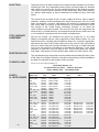
1
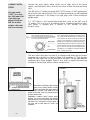
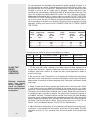
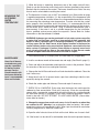
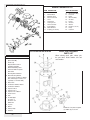
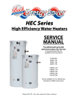
TO THE INSTALLER:
Please attach these instructions next to the
water heater.
TO THE CONSUMER:
Read these and all component instructions.
Please keep for future
reference. Please remember to return the
registration card.
Waranty, registration
card & parts list included.
INSTALLATION, OPERATION &
MAINTENANCE INSTRUCTIONS
BOCK RESIDENTIAL OIL-FIRED
WATER HEATERS
Model numbers: 20e, 20pp, 32E, 32EC, 32PP,
32PPC, 33E, 33PP, 40E, 40PP, 50ES, 50ESC,
51E, 51EC, 51PP, 51PPC, 71E, 120E
WARNING:
Improper installation, adjustment, alteration, service
or maintenance can cause serious injury or property damage. Refer to this manual. For assistance
or additional information, consult a qualified installer
or service agency.
WARNING:
If the information in these instructions is not followed exactly, fire or explosion may result and can
cause property damage, personal injury or death.
WARNING:
Follow minimum combustible clearance as noted
on water heater label. Do not install on combustible
flooring (see Figure 2, Page 3). Install in accordance with all local codes. In the absence of local
codes, refer to NFPA 31 or ANSI Z21.10.1.
CAUTION:
The recommended temperature for normal residential use is 120°F. The dial on the aquastat does not
always reflect the outcoming water temperature,
which could occasionally exceed 120°F. The variation in outcoming temperature could be based on
factors including but not limited to usage patterns
and type of installation. Test your water at the tap
nearest to the water heater. (See page 5 for measuring the outcoming water temperature).
WARNING:
Hotter water increases the risk of scald injury. Before changing the temperature setting, read the
instruction manual. Temperatures at which injury occurs vary with the individual’s age and length of
exposure.
The slower reaction times of children, elderly and
physically or mentally impaired persons increases
the scalding hazard to them. It is recommended lower
water temperatures be used where these situations
exist.
Households with small children or invalids may require a temperature setting less than 120°F to prevent
accidental contact with hot water.
To lower water temperature use point-of-use temperature limiting devices.
WARNING:
Flammable vapors may be drawn to this water heater from other areas of the structure by air currents.
Do not store or use any flammable liquids in the
vicinity of this heater.
WARNING:
Water heater blankets may restrict air flow to the
heater and cause fire, asphyxiation, personal injury
or death.
Bock Water Heaters, Inc.
110 South Dickinson Street • P.O. Box 8632 • Madison, WI 53708-8632
Phone: 608/257-2225 • Fax: 608/257-5304 • www.bockwaterheaters.com
CONSUMER
RESPONSIBILITIES
THIS MANUAL HAS BEEN PREPARED TO ACQUAINT YOU WITH THE INSTALLATION, OPERATION, AND MAINTENANCE OF YOUR WATER HEATER AND
TO PROVIDE IMPORTANT SAFETY INFORMATION.
FAILURE TO FOLLOW
THESE INSTRUCTIONS
OR ALL APPLICABLE
BUILDING CODES AND
REGULATIONS VOIDS
THE WARRANTY ON THIS
WATER HEATER.
The manufacturer of this water heater will not be liable for any damages caused
by failure to comply with the installation and operating instructions outlined on the
following pages. These instructions are a guide for the correct installation of the
water heater.
Read all instructions thoroughly before attempting installation or operation of the
water heater. Keep these and all component instructions for future reference.
If the installer lacks the necessary skills or has difficulty following the
directions, do not proceed but get help from a qualified person for that part of the
installation that is not understood.
MULTIPLE BURNER
INSTALLATION
SELECT THE RIGHT
LOCATION
Check for exhaust fans in
the heater room or adjacent areas which draw
combustion air away from
heater. THE HEATER
MUST HAVE COMBUSTION AIR TO OPERATE.
Local plumbing and electrical codes must be followed in the installation of this
water heater. In the absence of a local code use the UNIFORM PLUMBING
CODE and the NFPA Code. Local codes may supersede instructions in this installation manual.
When two or more burners are used, each unit should have a separate
supply line to the fuel pump to prevent nuisance lockouts caused by one or both
pumps starving for oil. If this is not possible, the use of a priority
control is recommended.
Check new equipment to see if all components are in good condition.
The water heater and oil burner may be shipped as separate units. The aquastat
and immersion well may be packed with the oil burner.
The new water heater requires fuel (#I or #2 heating oil), electricity and should be
close to the chimney and water supply. Locate the heater near a floor drain if possible for easy maintenance and protection if trouble should occur. Allow ample
space around the heater for servicing (see combustible clearance warning, page
1). Adequate air for combustion must be available. NOTE: Locate the heater so it
is not subject to physical damage by moving vehicles or possible flooding.
FIGURE 1
WHEN THE WATER HEATER IS USED IN A COMBINED APPLIANCE APPLICATION, PLEASE
CONTACT THE LOCAL DISTRIBUTOR OR THE FACTORY FOR INSTALLATION INSTRUCTIONS ON
“SYSTEM PLUS”.
DO NOT INSTALL THE WATER HEATER ON COMBUSTIBLE FLOORING (see Figure 2). Refer to NFPA 31 or
contact Bock Water Heaters with questions concerning proper flooring materials.
Minimum clearance to combustible construction is:
SIDES 6"; BACK 6"; FRONT 24". The installation of
this water heater must conform with local codes and
ordinances. In the absence of local codes, the installation must comply with the National Fire Protection
Association (NFPA 31) Code.
–2–
CONNECT WATER
PIPING
Hot water outlet
(“HOT”) is on tank
top. Cold water inlet
is on right front
bottom of 33E and
40E. On all other
models, cold water
inlet is on tank top.
Connect the water piping, being careful not to apply heat to the heater
nipples. Install dielectric unions and shut off valves on both hot and cold water
lines.
The 40E and all “C” models (example: 32EC, 51PPC) have a 1” NPT tapping located on the front left side of the tank. This is an alternate outlet for use with combined
appliance applications. If this fitting is not used, plug it with a fitting suitable for
potable water.
A 1” NPT fitting is also located behind the drain valve on the 40E and all
“C” models. This is for use as an alternate inlet or a combined appliance return.
Your heater is shipped with a reducer in this location to mount
the drain valve.
NOTE: INDEX MARK ON INLET BUSING MUST
POINT TOWARD ARROW ON DECAL. HOLD
INLET BUSHING OR NIPPLE WHEN TIGHTENING
FITTINGS. ROTATING BUSHING COULD DRASTICALLY REDUCE PERFORMANCE.
INDEX MARK
INLET BUSHING
The 33E and 40E models are equipped with a
brass inlet bushing installed in the tank. Heaters equipped with this bushing are marked next
to the inlet by the decal shown on the left. The
purpose of this bushing is to help keep the tank
bottom free of sediment by aiding tank flushing.
This bushing must be located as shown on the
decal to function properly. Do not allow the bushing to rotate out of position when tightening the
inlet fittings. In installations requiring high flow
rates, contact the factory.
The drain valve fitting may be used as an alternate cold water inlet on heaters
equipped with a dip tube, as shown in Figure 3. By plumbing a “T” into the drain
fitting, the cold water inlet can be relocated to this point. The dip tube must be
removed and its fitting plugged. Figure 3 also shows a copper loop heat trap
installed on the hot water outlet to reduce standby losses.
FIGURE 2
The drain valve fitting may be used as
an alternate cold water inlet on heaters
equipped with a dip tube, as shown in
Figure 3. By plumbing a “T” into the drain
fitting, the cold water inlet can be
relocated to this point. The dip tube
must be removed and its fitting plugged.
Figure 3 also shows a copper loop heat
trap installed on the hot water outlet to
reduce standby losses.
Note: When converting to this configuration on an existing heater, visually
inspect the heater and make certain it
does not have scale buildup on the
bottom of the tank. Scale can restrict the flow
of water into the tank.
CAUTION!! Scalding injury and/or water
damage can occur from either the manual
lifting of the lever or the normal operation of the
T&P valve if it is not piped to a proper drain. If
the valve fails to flow water or reseat, call
a plumber.
–3–
FIGURE 3
Inspect the incoming water line for check valves or water pressure reducing
valves. Any type of check valve may cause pressure to build up in the heater and
cause tank failure. If the heater is installed in a closed system or if backflow preventers and pressure regulators are installed, add an expansion tank. Do not try
to heat hard water. Install a water softener if the heater is being used in a hard
water area (water hardness more than 7 grains).
CONNECT TO
CHIMNEY
An approved temperature and pressure (T&P) relief valve is factory installed in
the opening provided in the upper right hand side of the heater. Pipe the T&P to
within 6" of the floor or to a floor drain with a free flowing drain pipe. Do not install
a check valve in the cold water line.
Using “L” or “A” type venting, connect the heater to the chimney. Use the same
size smoke pipe as the heater flue pipe (on models 20e, 20pp, 32E, 32PP and
33E, you may use 4" with a reducer if needed).
WARNING: On Models 40E, 5OES, 50ESC, 51E, 51EC, 51PP, 51PPC. 71E and
120E, do not reduce the smoke pipe diameter. Run a separate smoke pipe from
the water heater to the chimney wherever possible.
MOUNT THE OIL
BURNER
CONNECT THE
ELECTRICITY
CONNECT THE OIL
LINE
WARNING!! WHEN YOU
INSTALL THE BYPASS
PLUG YOU MUST RUN A
TWO-LINE SYSTEM.
–4–
If it is necessary to tee into an existing smoke pipe, be sure the connector being
teed into is large enough to accommodate the products of combustion of all units
attached to it. When teeing into another connector, run in at 45° angle (see Figure
1). Install a draft regulator control only if necessary. Overfire draft should not be
positive. Stack draft should be -.02” W.C. minimum to -.05” W.C. maximum; CO2
should be a minimum of 11%. If a draft control is installed on the chimney,
another one on the heater is not needed.
The oil burner is equipped with a primary relay. An aquastat with immersion
well is packed with the burner. The thermostat is factory set at 120°F for residential use (see caution on page 1 regarding temperature variations). Install the
immersion well with the aquastat and check the bulb length (see “Burner &
Controls” section, page 10).
Remove the cardboard core from the burner opening. Mount the burner on stud
bolts and place the gasket (supplied) between the burner flange and the heater.
Secure the burner to the heater with 1/4 -20 nuts (supplied). Open the inspection
door on the heater and check the burner tube with a mirror before firing to
be sure the opening is not blocked (see Maintenance and Service sections on
pages 6 and 7 for troubleshooting).
All wiring must comply with applicable codes and ordinances. The primary relay
is wired to the burner at the factory. Install the aquastat well in the 3/4" tapping at
the front of the heater. Be sure the sensing bulb is inserted all the way into the
well. For Honeywell aquastats, tighten the screw on top of the aquastat to secure
the control to the well. For Carlin EZ-Temp aquastats, refer to the pre-packaged
installation guide for proper set-up procedure. Refer to drawings for correct models. Connect the power supply to the aquastat and run through a fused disconnect switch (attached to heater in field). See Figure 1.
Gravity System: The oil burner is normally equipped with a single-stage pump
equipped for one line (gravity) flow. Use 1/2" O.D. soft copper tubing and attach
with flared fittings. DO NOT USE COMPRESSION FITTINGS. Install the shut
off valve and oil filter in the oil line. Follow the pump manufacturer’s instructions
(attached to the pump).
Lift System: The burner should be ordered with a 2-stage pump. Run a 2-line
system (suction and return lines). Install the bypass plug according to the
instructions attached to pump (plug is in a bag with an instruction sheet).
For any horizontal run exceeding the maximum length specified in Figure 4, or
any lift of more than 10 feet, a booster pump must be used. Booster pumps may
be obtained from Sun Tec Hydraulics, Rockford, Illinois. Booster pumps must be
installed as close to the oil supply tank as possible. Suction and return lines
should be the same diameter and both go within 6” of the bottom of the tank. The
return line should stop slightly above the suction line. Use a minimum of fittings.
Make bends in the tubing with as large a radius as possible. DO NOT USE COMPRESSION FITTINGS. Caution must be used in the final connection to the burner
so as not to strain the fuel unit. Before attaching the tubing to the burner, form a
coil in the tubing to minimize any vibration. Bury the oil lines in the floor for quiet
operation, making sure there are NO CONNECTIONS OR FITTINGS UNDER
THE FLOOR.
FIGURE 4: MAXIMUM LIFT & HORIZONTAL RUN
1-Pipe
Single Stage
Horizontal
2-Pipe
System
Pump
Run
System
3/8” O.D.
1/2” O.D.
Lift
Tube
Tube
Lift
0’
4’
7’
8’
65’
45’
31’
16’
100’
100’
100’
64’
0’
4’
7’
10’
Two-Stage
Pump
3/8” O.D.
Tube
75’
64’
55’
47’
Your log (or one similar to this) must be filled out as follows:
Date
Time
Test person’s name
Set temp. oF
PLACE THE
WATER
SYSTEM IN
OPERATION
Warning: Handhole
cover may loosen
during shipping –
check for tightness
before putting heater
in operation.
–5–
Horizontal
Run
1/2” O.D.
Tube
100’
100’
100’
100’
Outlet temp. oF
1. Fill the tank with water, opening a hot water faucet to allow trapped air to
escape from the heater. Open the cold water inlet valve. Shut off each faucet as
it delivers water that is free of air. Inspect for leaks. Never operate an empty or
partially full heater.
2. Be sure the oil tank is filled with #1 or #2 heating oil. Remove the transformer
hold down screw and swing the transformer back open on the hinge. Rotate the
blower wheel a few times to loosen the pump shaft. Swing the transformer closed
and fasten.
3. Bleed air from the oil line by opening the bleed valve on the fuel pump. Attach
a small plastic tube to the bleed valve fitting on the pump and run to a gallon
container. Turn on the electricity and set the thermostat so the burner motor runs.
The heater will not ignite when the bleed valve is open. Bleed the line until the oil
is completely clear, not milky or opaque. The oil must be transparent and free of
air bubbles and froth. To keep the burner control from locking out while bleeding
the pump, attach a jumper between the flame detector terminals after starting the
burner. Remove the jumper when finished. Shut the bleed valve and the burner
will ignite. Remove the plastic tubing. Set the pump pressure to 100 PSI for
Wayne, Carlin and Beckett burners and 150 PSI for Riello burners.
4. Adjust the burner combustion air in accordance with the burner manufacturer’s
instructions. Using combustion instruments, check the C02 and smoke. The C02
should be at least 10 1/2% minimum with 0-to-trace smoke on the Bacharach
scale.
MEASURING THE
OUTCOMING
WATER
TEMPERATURE
5. While the burner is operating, disconnect one of the yellow cad cell wires.
Check to see that the burner control locks out in the time specified on the control.
Reattach the wire and reset the control. The burner should restart. Note: You may
have to wait a minute before resetting the control.
6. The thermostat is factory set at 120°F for residential use. (See caution on page
1 regarding temperature variations. It is the responsibility of the homeowner and
installer to verify that the installer follows the recommended quantitative testing
for measuring the outcoming water temperature. To make sure that the system
works properly after installation and in the future, it is recommended that the
heater’s performance be measured and monitored. Run water out of the tap nearest the heater until it comes out warm. Using a calibrated thermometer, take a
measurement. If the water is not at a suitable temperature for the installation,
have a qualified service person adjust the aquastat. Contact Bock for further
information on the thermometer if needed.
WARNING: Hydrogen gas can be produced in a hot water system served by
a heater that has not been used for a long period of time (generally two
weeks or more.) Hydrogen gas is extremely flammable. To reduce the risk
of injury, open the hot water faucet at the highest location in the house for
several minutes before using any electrical appliance connected to the hot
water system. If hydrogen is present, there may be an unusual sound such
as air escaping through the pipe as the water begins to flow. Do not smoke
or allow an open flame near the faucet at the time it is open.
MAINTENANCE
Have the oil burner
serviced once each
year by a qualified
oil burner service
person. Service
should comply with
the burner manufacturer’s recommendations and include:
1. Oil the burner motor (5-10 drops) with #10 SAE motor oil (if applicable).
2. Install a new burner nozzle of the correct rate and angle. (See Chart A, page 11).
3. Clean and adjust the electrodes and inspect for cracks in the porcelain. Check
for corrosion on the buss bars and ignitor terminals.
4. Change the fuel oil filter and have the oil tank checked for sediment. Clean the
tank if necessary.
5. Keep the oil tank full to prevent water vapor from collecting inside the tank,
especially during the summer.
6. Check the smoke pipe and chimney. Clean and repair if necessary.
7. EVERY SIX to 12 MONTHS. Drain water from the heater tank and inspect for
sediment or lime accumulation. Flush out if necessary. If lime has accumulated,
remove with a commercial compound for dissolving lime or by scraping through
the hand hole opening (if supplied). Check water softening equipment if lime is
found in the tank. DO NOT ATTEMPT TO HEAT HARD WATER. (See maintenance label on heater.)
8. Change the magnesium anode rods every six to 12 months or when they
are reduced to 3/8” diameter (see maintenance label on heater). We recommend the installer use PermaBond LH-050. Teflon tape should not be used when
installing magnesium or aluminum anode rods.
9. Open the relief valve test lever to flush out the tank. Make sure it reseats itself.
10. If the heater is to be shut off in cold weather, drain the tank to prevent freezing.
–6–
SERVICE
1. Check the fuel supply, electrical wiring and fuses, and make sure temperature
control is calling for heat.
2. If the motor runs but there is no flame, remove the electrode assembly, clean,
readjust to the burner manufacturer’s specifications, check the electrode porcelain for cracks and replace if necessary. Check the transformer to see if it is producing a strong spark. (Use extreme CAUTION: The transformer has a 10,000
volt output). Check that the coupling between the motor and pump shaft is not
slipping. Check the set screw on the blower wheel for tightness. Clean or replace
the nozzle with the correct size and spray angle (see Chart A, page 11).
3. Bleed the pump and check for clear, air-free oil. If the oil is milky or frothy, check
the line for air leaks at fittings. Tighten all fittings again. Check the filter gaskets
and make sure cartridge is clean.
4. If the burner motor does not run, check the motor thermal overload button (red
button on end of motor). Reset the primary control by pushing the reset button on
the control. If the burner motor still does not run after resetting the control, turn off
the electricity and replace the flame detector (with the same make) located in the
burner compartment. Reset the primary control. If the motor still
does not run, replace the control.
5. If the burner ignites and runs a short time (30-40 seconds), then goes out on
safety, replace the flame detector. If the burner still runs only a short time, replace
the control.
6. If there is a smell of oil or combustion products, remove and clean the electrode
assembly (see No. 2 above). Check the draft in the stack above the heater. Stack
draft (pull in) should be -.02” W.C. minimum to -.05” W.C. maximum.
Check for exhaust fans in the heater room or adjacent areas which draw combustion air away from heater. THE HEATER MUST HAVE COMBUSTION AIR TO
OPERATE.
For more information, contact your installer, the nearest Bock distributor, or write,
call or fax:
BOCK WATER HEATERS, INC.
110 South Dickinson Street, Madison, WI 53703
Phone: 608/257-2225 • Fax: 608/257-5304
–7–
WIRING
FIGURE 5: Carlin burner w/ Carlin EZ-Temp
For Models: 32, 33, 40, 50, 51, 71, 120E
(see burner manufacturer’s instructions for 20e;
60200 primary w/ three wire harness)
FIGURE 6: Beckett or Wayne burner w/ Carlin EZ-Temp
For Models: 32, 33, 40, 50, 51, 71, 120E
FIGURE 7: Honeywell L4103A-1142
For Models: 32, 33, 40, 51, 71E
FIGURE 8: Honeywell L4006A w/ L8080B
For Models: 50, 120E
FIGURE 7 NOTES:
Set point 120°
FIGURE 4 NOTES:
High limit: 190°
Aquastat:
120° set point
15° differential
L4080B
L4006A
–8–
BURNER COMPONENTS
BURNER COMPONENTS LIST
ITEM DESCRIPTION
1.
2.
3.
4.
5.
6.
7.
8.
9.
10.
11.
Motor
Blower Wheel
Burner Housing
Motor Cord Cover
J-Box
Transformer
Housing Cover
Slot Cover Plate
Inner Air Band
Outer Air Band
Coupling (not shown)
OIL FIRED WATER HEATER
ITEM
1.
2.
3.
4.
6.
8.
9.
10.
11.
12.
13.
14.
15.
16.
17.
18.
19.
20.
21.
22.
23.
DESCRIPTION
Cold Water Inlet Dip Tube
(N/A 33E & 40E)
Plastic Cap
Magnesium Anode Rod
(aluminum avaliable)
Name Plate/Rating Label
Immersion Well & Aquastat
Drain Valve
Mounting Bracket Gasket
Burner Mounting Bracket
(part of jacket assembly on Models
20e, 32E through 51 Series; sold
separately on 71E and 120E)
Bottom Pan
Combustion Chamber Sleeve
Combustion Chamber
Inspection Block
Inspection Door
Inspection Door Gasket
Heater Jacket
Tank
Hot Out Nipple
51 Series: 1”
AlI others: 3/4”
50ES: N/A
Top Pan
Burner
Primary Relay
Cad Cell
–9–
ITEM DESCRIPTION
12.
13.
14.
15.
16.
17.
18.
19.
20.
21.
22.
Oil Line Assembly
Fuel Unit
Elbow
Gun Assembly
Air Tube
Flange
Air Cone
Gasket
Nozzle (not shown)
Relay
Cad Cell
BOCK TANK ASSEMBLY
PARTS LIST
When ordering repair parts, always give
the part name, model number, size and
serial number.
Handhole cover plate and gasket
(for 50ES only) not shown.
LIMITED WARRANTY
WARRANTY
COVERAGE
COMPANY’S
RESPONSIBILITY
BURNER
& CONTROLS
20e, 32E, 33E, 40E, 51E, 71E
residential applications:
This warranty covers “Bock” Water Heater models 20e, 20pp, 32E, 32EC, 32PP,
32PPC, 33E, 33PP, 40E, 40PP, 50ES, 50ESC, 51E, 51EC, 51PP, 51PPC, 71E
and 120E. Bock Water Heaters, Inc., a division of Bock Corporation–a Wisconsin
corporation–at 110 South Dickinson Street, Madison, WI 53703 (“Company”),
warrants to the owner, the tank of this water heater will not leak due to defective
materials or workmanship for FIVE years from the date of original installation. If
the water heater is installed in other than a single family dwelling, this warranty is
limited to THREE years from the date of original installation. The company also
warrants that no other part of this water heater will fail due to a defect in material
or workmanship for one year.
The company’s responsibility is to repair or replace, at our option with the prevailing comparable Bock model, any part of the equipment sold by the Company
which proves to be defective in material or workmanship, including the tank,
during the warranty period when installed in accordance with applicable codes
and ordinances, and operated and maintained in accordance with our instructions, subject to the conditions and exceptions indicated below. Our liability, in the
event of leakage or other malfunction, is strictly limited to repair or replacement of
the defective heater or part, as provided herein. We are not responsible hereunder for incidental property damage or personal injury, consequential costs or
damage. Equipment that is repaired or replaced will carry the unexpired portion
of the original equipment warranty.
Any burner and/or controls used on a Bock water heater other than the ones recommended by Bock Water Heaters Inc., and listed by Underwriters Laboratories,
Inc., will void the warranty.
Bock Water Heaters, Inc. specifies burners and controls on the basis of safety,
reliability and performance. Only the following burners and controls have been
tested and approved by Bock Water Heaters, Inc. and Underwriters Laboratories,
Inc., to meet the stringent standards required by both. (Refer to chart A, page
11).
Honeywell L4103A combination aquastat and high limit controller. One well is
needed. Part #138134E. (See figure 7).
White Rodgers 11C30-11 combination aquastat and high limit controller. One
well is needed. Part #F89-0214.
50ES, 120E &
commercial
applications:
OWNER’S
RESPONSIBILITY
– 10 –
Carlin EZ-Temp 90000B — Part #21585. One well is needed — Part #21587.
(See Figure 5, 6).
Honeywell L4006A (aquastat) and L4080B (limit control). Two wells are needed. Part #123871B. Not to be used on 32E series. (See Figure 8).
Carlin EZ-Temp 90000C — Part #21582. Two wells are needed — Part
#21587. (See Figure 5, 6).
Carlin EZ-Temp 90300B — Part #21589. Two wells are needed — Part
#21587. (See Figure 5, 6)
At the company’s request, the owner is to return to the factory at Madison, WI,
any part, including the tank, defective in material or workmanship, and pay all
transportation charges for such return parts and for replacement parts sent
from the factory to the owner.
EXCEPTIONS
TOTAL WARRANTY
COMMITMENT
REGISTRATION CARD
TO MAKE A CLAIM
CHART A
UL LISTED BURNERS
– 11 –
The owner will pay all labor charges for the removal and installation of such parts,
including the tank. Any replacement water heater furnished under this warranty
shall remain in warranty only for the unexpired portion of the original warranty.
The owner will have annual inspections of the anode rods. Bock Water Heaters,
Inc. requires paid receipts to show maintenance of anodes on glass lined tank
claims.
This warranty will not apply to tanks or parts subject to misuse, abuse, neglect,
alteration, accident, excessive temperature, excessive pressure, lime, silt or sediment accumulation, corrosive atmosphere, the removal of magnesium anode
rods, noise, odor, rusty water, or the installation of an insulation blanket, installation outside of the United States (excluding Canada), or on which the
serial numbers have been altered. The warranty also does not apply when the
water heater is installed without a new temperature and pressure relief valve and
is not installed in accordance with local codes and ordinances.
We will not assume, nor authorize any person to assume for us, any other
liability in connection with the sale or operation of Bock Water Heaters, Inc. Any
implied warranties, including merchantability or fitness for a particular application,
imposed on the sale of this heater under laws of the state of sale are limited to
one year. Some states do not allow limitations on how long an implied warranty
lasts, or for the exclusion of incidental or consequential damages, so the above
limitations or exclusions may not apply to you. This warranty gives you specific
legal rights, and you may also have other rights which vary from state to state.
The attached warranty registration card should be returned within 30 (thirty) days
of the date of installation, otherwise, the date of manufacture will be recorded as
the date of installation for the purpose of this warranty.
Contact your nearest Bock distributor or:
Bock Water Heaters, Inc.
110 South Dickinson Street • Madison, WI 53703
Phone: 608/257-2225 • Fax: 608/257-5304
BOCK
MODEL (OIL)
32E, 32EC, 33E
32PP, 32PPC
40E
5IE, 51EC
50ES, 120E
51PP, 51PPC
71E
32E, 32EC, 33E
32PP, 32PPC
40E
51E, 51EC
50ES, 120E
51PP, 51PPC
71E
32E, 32EC, 33E
32PP, 32PPC
51E, 51EC
50ES
51PP, 51PPC
120E
71E
20e, 20pp
32E, 32EC, 33E
32PP, 32PPC
51E, 51EC
50ES
51PP, 51PPC
71E
BURNER
MFR.
WAYNE
WAYNE
WAYNE
WAYNE
WAYNE
WAYNE
WAYNE
BECKETT
BECKETT
BECKETT
BECKETT
BECKETT
BECKETT
BECKETT
RIELLO
RIELLO
RIELLO
RIELLO
RIELLO
RIELLO
RIELLO
CARLIN
CARLIN
CARLIN
CARLIN
CARLIN
CARLIN
CARLIN
MODEL/
OEM #
MSR/371-001B
HS/371-009HS
MSR/371-030B
MSR/371-003B
MSR/371-029B
HS/371-011HS
MSR/371-017B
AF/BK3
AF/BK3
AF/BK4
AF/BK5
AF/BK5
AF/BK5
AF/BK7
R35.3/C8511221
R35.3/C8511221
R35.3/C8511223
R35.3/C8511222
R35.3/C8511223
R35.3/C8511223
R35.5/C8512220
EZ-LF/997843CT
EZ-1/96828-32E
EZ-1/96828-32PP(C)
EZ-1/96828-51E
EZ-1/96828-50ES
EZ-1/96828-51PP(C)
EZ-1/96828-71E
MAX
INPUT
0.75 X 80A
0.75 X 80A
0.90 X 70A
1.10 X 80A
1.10 X 80A
1.10 X 80A
1.25 X 70B
0.75 X 80A
0.75 X 80A
0.85 X 80A
1.00 X 80A
1.00 X 80A
1.00 X 80A
1.25 X 80B
0.60 X 60B
0.60 X 60B
1.10 X 80A
0.85 X 60B
1.10 X 80A
1.00 X 60B
1.00 X 60B
0.40 X 60A
0.75 X 70A
0.75 X 70A
1.10 X 70A
1.00 X 70A
1.10 X 70A
1.25 X 60A
MODEL
OEM #
40F5/C8512180
40F5/C8512180
40F5/C8512181
40F5/C8512181
40F5/C8512181
40F5/C8512181
40F5/C8512182
MAX
INPUT
0.60 X 60B
0.60 X 60B
0.90 X 60B
0.90 X 60B
0.90 X 60B
0.90 X 60B
1.00 X 60B
Bock Water Heaters, Inc.
110 South Dickinson Street • P.O. Box 8632 • Madison, WI 53708-8632
Phone: 608/257-2225 • Fax: 608/257-5304 • www.bockwaterheaters.com
– 12 –
Form 23420
Rev 4
3/2007