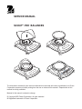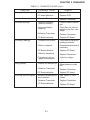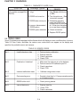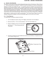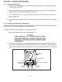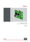
1
SERVICE MANUAL SCOUT® PRO BALANCES Ohaus Corporation 19A Chapin Road, P.O. Box 2033, Pine Brook, NJ 07058-2033 (973) 377-9000 SERVICE MANUAL SCOUT® PRO BALANCES The information contained in this manual is believed to be accurate at the time of publication, but Ohaus Corporation assumes no liability arising from the use or misuse of this material. Reproduction of this material is strictly prohibited. Material in this manual is subject to change. © Copyright 2003 Ohaus Corporation, all rights reserved. ® Registered trademark of Ohaus Corporation. TABLE OF CONTENTS Page No. CHAPTER 1 INTRODUCTION 1.1 Introduction ............................................................................................................. 1-1 1.2 Service Facilities ..................................................................................................... 1-1 1.3 Tools and Test Equipment Required....................................................................... 1-2 1.3.1 Special Tools and Test Equipment List ............................................................. 1-2 1.3.2 Standard Tools and Test Equipment List ........................................................... 1-2 1.4 Test Masses Required ............................................................................................ 1-2 1.5 Specifications .......................................................................................................... 1-3 CHAPTER 2 DIAGNOSIS 2.1 Troubleshooting ...................................................................................................... 2-1 2.2 Diagnostic Guide..................................................................................................... 2-1 2.2.1 Diagnosis........................................................................................................... 2-1 2.3 Error Codes ............................................................................................................. 2-4 CHAPTER 3 REPAIR PROCEDURES 3.1 Repair Procedures .................................................................................................. 3-1 3.1.1 Cover Removal .................................................................................................. 3-1 3.1.2 Printed Circuit Board Replacement ................................................................... 3-2 3.1.3 Transducer Replacement .................................................................................. 3-4 CHAPTER 4 TESTING 4.1 Testing .................................................................................................................... 4-1 4.1.1 Operation Test ................................................................................................... 4-1 4.1.2 Segment Display Test........................................................................................ 4-1 4.2 Performance Tests .................................................................................................. 4-1 4.2.1 Repeatability Test .............................................................................................. 4-2 4.2.2 Off-Center Load Test .......................................................................................... 4-3 4.2.3 Linearity Test ..................................................................................................... 4-3 4.3 Down Stop Adjustment ............................................................................................ 4-4 CHAPTER 5 DRAWINGS AND PARTS LISTS 5.1 Drawings ................................................................................................................. 5-1 5.2 Parts Lists................................................................................................................ 5-3 APPENDIX A SERVICE TOOL INSTRUCTIONS A. Service Tools Instructions ...................................................................................... A-1 A.1 Requirements for Scout Pro Tools ......................................................................... A-1 A.2 Software Installation ............................................................................................... A-1 A.3 Hardware Installation ............................................................................................. A-1 A.4 Special Instructions for USB Interface .................................................................... A-2 A.5 Using Configtool.Exe ............................................................................................. A-3 A.6 Final Service Calibration ........................................................................................ A-5 i APPENDIX B FACTORY CALIBRATIONS Page No. B. Factory Calibrations ............................................................................................... B-1 B.1 Service Calibration................................................................................................. B-1 B.2 Factory Calibration ................................................................................................. B-3 LIST OF TABLES TABLE NO. 1-1 1-2 2-1 2-2 4-1 4-2 4-3 4-4 5-1 TITLE Page No. Calibration Points ................................................................................................. 1-2 Specifications ....................................................................................................... 1-3 Diagnostic Guide .................................................................................................. 2-2 Error Codes .......................................................................................................... 2-4 Types of Performance Tests ................................................................................. 4-1 Test Masses ......................................................................................................... 4-3 Test Mass Values ................................................................................................. 4-5 Transducer Adjustment Tolerances ...................................................................... 4-5 Replacement Parts List ........................................................................................ 5-3 LIST OF ILLUSTRATIONS FIGURE 3-1 3-2 3-3 3-4 4-1 4-2 5-1 A-1 A-2 A-3 A-4 A-5 A-6 A-7 B-1 TITLE Page No. Shipping Lock....................................................................................................... 3-1 Bottom of Balance ................................................................................................ 3-1 Printed Circuit Board removal............................................................................... 3-2 Transducer Removal ............................................................................................ 3-4 LCD Full Display .................................................................................................. 4-1 Transducer Front View - Down Stop Adjustment .................................................. 4-4 Scout Pro Exploded View ..................................................................................... 5-2 Screw and Housing Removal .............................................................................. A-2 Connector J3 Location......................................................................................... A-2 Connector J3 Shorted .......................................................................................... A-2 Screen 1 .............................................................................................................. A-3 Screen 2 .............................................................................................................. A-4 Screen 3 .............................................................................................................. A-4 Screen 4 .............................................................................................................. A-5 IC U9 Connections .............................................................................................. B-2 ii CHAPTER 1 INTRODUCTION 1.1 INTRODUCTION This service manual contains the information needed to perform routine maintenance and service on the Ohaus Scout ® Pro Balances. The contents of this manual is contained in five chapters and are listed as follows: Chapter 1 Introduction - Contains information regarding service facilities, tools, test equipment, calibration masses and specifications. Chapter 2 Diagnosis - Contains a diagnostic guide for troubleshooting problems and error code tables. Chapter 3 Repair Procedures - Contains disassembly/assembly and replacement procedures. Chapter 4 Testing - Contains an operational test, a segment display test and performance tests. Chapter 5 Drawings and Parts Lists - Contains an exploded view drawing and a parts list. Before servicing the balance, you should be familiar with the Instruction Manual which is packed with every balance. The procedures in this manual assumes the technician performing them has a working knowledge of the use of standard hand tools and the repair of precision instruments. 1.2 SERVICE FACILITIES To service the Scout® Pro balances, the service area should meet the following requirements: Should be temperature controlled and meet the balance specifications for temperature environmental requirements. See specifications for temperature ranges of the various models. Must be free of vibrations such as fork lift trucks close by, large motors, etc. Must be free of air currents or drafts from air conditioning/heating ducts, open windows, people walking by, fans, etc. Area must be clean and air must not contain excessive dust particles. Work surface must be stable and level. Work surface must not be exposed to direct sunlight or radiating heat sources. 1-1 CHAPTER 1 INTRODUCTION 1.3 TOOLS AND TEST EQUIPMENT REQUIRED In order to properly service the Scout Pro balances, certain Ohaus special tools and test items are required in addition to standard electronic tool kits. These items are listed as follows: 1.3.1 Special Tools and Test Equipment List 1. Alternate voltage Power Adapter if local power requirements do not match Balance Adapter voltage ratings. 2. Scout Pro RS232 option PN 71147376. 3. A PC running Microsoft Windows NT 4.0 or later, or Microsoft Windows 98 or later. 3. Scout Pro instruction manual. 4. Scout Pro Tools.zip. 5. Set of Feeler gauges ranging from 0.40mm/0.16in. to 0.65mm/0.026in. 6. Micro sized alligator clip. 1.3.2 Standard Tools and Test Equipment List 1. Standard Electronics Tool Kit. 2. Digital Voltmeter (DVM) Input impedance of at least 10 megohms in the 1 Volt dc position. 3. Masses totaling up to 6000 grams are required. Ohaus makes various calibration sets available. Please contact your nearest Ohaus dealer for further details. 1.4 TEST MASSES REQUIRED The masses required to test the Scout Pro balances must meet or exceed the requirements of ASTM Class 4 Tolerance. The calibration points are listed in Table 1-1. TABLE 1-1. CALIBRATION POINTS CAPACITY 200g 400g 600g 2000g 4000g 6000g SPAN CAL POINT 200g 200g 300g 2000g 4000g 6000g 1-2 LINEARITY CAL POINTS 100g, 200g 200g, 400g 300g, 600g 1000g, 2000g 2000g, 4000g 3000g, 6000g CHAPTER 1 INTRODUCTION 1.5 SPECIFICATIONS Specifications for the Scout Pro balances are listed in Table 1-2. When a balance has been serviced, it must meet the specifications listed in the table. Before servicing the balance, determine what specifications are not met. TABLE 1-2. SPECIFICATIONS Capacity (g) 200 400 400 600 2000 4000 6000 Readability (g) 0.01 0.1 1.0 Repeatability (Std. Dev.) (g) 0.01 0.1 1.0 Off Center Loading (g) ±0.01 ±0.1 ±1.0 Linearity (g) ±0.01 ±0.1 ±1.0 Tare range To capacity by subtraction Over Range Capacity Capacity + 90d Stabilization Time 3 seconds Operating Temp. Range Power Requirements Item Numbers 50° to 104° F/10° to 40° C AC Adapter (included) 4 AA Batteries (not included) SPx202 SPx402 SPx401 SPx601 SPx2001 SPx4001 SPx6000 1-3 CHAPTER 1 INTRODUCTION 1-4 CHAPTER 2 DIAGNOSIS 2.1 TROUBLESHOOTING This section of the manual specifies problem areas of the balance which can occur. Information is contained to isolate specific problems using Table 2-1, Diagnostic Guide, and Table 2-2, Error Codes. Follow all directions step by step. Make certain that the work area is clean and use care when handling components of the balance. 2.2 DIAGNOSTIC GUIDE Table 2-1 is a diagnostic guide designed to help locate the problem area quickly and easily. To use the table, first locate the symptom that you are observing. Follow the symptom column and review the probable cause column and remedy column. The probable causes are listed with the most common cause first. If the first remedy does not fix the problem, proceed on to the next remedy. Before attempting to repair the Balance, read all chapters of this manual to familiarize yourself with the balance components and operation. Do not attempt repairs unless you fully understand the operation of the balance. 2.2.1 Diagnosis 1. Isolate and identify the symptom. 2. Refer to Table 2-1 Diagnostic guide and locate the symptom. 3. Follow the suggested remedies in the order that they appear. 4. Perform the indicated checks, or see the appropriate section of the manual. 5. Repair or replace the defective section of the balance. NOTE: If more than one symptom is observed, it is necessary to approach one area at a time, and also remember, that the symptoms may be interrelated. In the event that erratic or fluctuating weight readings are observed, it is necessary to isolate the problem to either the mechanical area or the electronic area of the balance. The repeatability test will quickly point out whether the Transducer (8) is operating properly or whether the problem is due to an electronic malfunction. If a problem arises that is not covered in this manual, contact Ohaus Corporation for further information. 2-1 CHAPTER 2 DIAGNOSIS TABLE 2-1. DIAGNOSTIC GUIDE SYMPTOM No display. Low BAT displayed. Stays in segment check. Always displays zero. PROBABLE CAUSE 1. No power. REMEDY 1. Check AC Adapter. 2. Power Jack defective. 2. Replace Power Jack. 3. Weak battery. 3. Replace. 4. Battery connector - poor contact. 4. Clean or replace. 5. PC Board defective. 5. Replace PC Board. 1. Weak battery. 1. Replace battery. 2. AC Adapter defective or wrong type being used. 2. Replace AC Adapter. 3. PC Board defective. 3. Replace PC Board. 1. Weak battery. 1. Replace battery. 2. PC Board defective. 2. Replace PC Board. 1. Possible power surge. 1. Perform linearity calibration. 2. Down stop improperly set. 2. Set per specifications. Cannot calibrate. Displays (Err2) 3. Transducer not connected. 3. Plug in Transducer. 4. Defective Transducer. 4. Replace Transducer. 5. PC Board defective. 5. Replace PC Board. 1. Incorrect calibration masses. 1. Use correct masses. 2. Transducer not connected. 2. Plug in Transducer. 3. Defective Transducer. 3. ReplaceTransducer. 4. PC Board defective. 4. Replace PC Board. 1. Missing Pan. 1. Put pan on balance 2. Down Stop improperly set. 2. Check stops and reset if necessary. 3. Transducer zero has shifted. 3. Perform factory calibration B.1 or B.2 2-2 CHAPTER 2 DIAGNOSIS TABLE 2-1. DIAGNOSTIC GUIDE (Cont.) SYMPTOM Displays (Err2) (Cont.). PROBABLE CAUSE 4. Defective Transducer. REMEDY 4. Replace Transducer. 5. PC board defective. 5. Replace PCB. Exceeds off center load limit. 1. Defective Transducer. 1. Replace Transducer. Inaccurate readings. 1. Improper calibration (Span or Linearity). 1. Perform linearity calibration. 2. Not zeroed before weighing. 2. Press Zero On with no weight on the Pan, then weigh. 3. Defective Transducer. 3. Replace Transducer. 4. PC Board defective. 4. Replace PC Board. 1. Unstable environment. 1. Check area for vibrations, leveling and drafts. 2. Debris in balance. 2. Disassemble and clean if necessary. 3. PC Board defective. 3. Replace PC Board. 4. Defective transducer. 4. Replace Transducer. 5. Transducer Lock engaged or misaligned. 5. Unlock or realign. Fluctuating readings. Drifting display. 1. Balance not warmed up. 1. Allow balance to stabilize. 2. Defective Transducer. 2. Replace Transducer. 3. PC Board defective. 3. Replace PC Board. Error code (Err#) on display. 1. Balance has detected an 1. See Table 2-2, Error error condition. Codes. 2. Defective Transducer. 2. Replace Transducer. 3. PC Board defective. 3. Replace PC Board. 2-3 CHAPTER 2 DIAGNOSIS TABLE 2-1. DIAGNOSTIC GUIDE (Cont.) SYMPTOM PROBABLE CAUSE REMEDY RS232 Not functioning. 1. Improper Print Menu set- 1. Check all settings. (Menu (On models equipped with tings. item Power must be set RS232). to ON.) 2. RS232 not turned on. 2. Turn the option on. (See instruction manual). 3. RS232 does not stay on. 3. If batteries are being used, the RS232 turns off when the unit is turned 4. Loose or disconnected off. Either turn the option RS232 option. on or use the ac adapter. 5. RS232 option defective. 4. Check connection. 5. Replace RS232 option. 2.3 ERROR CODES Scout Pro balances are equipped with software which will display an error condition when it occurs. Table 2-2 Error Codes, describes the various error codes which can appear on the display and specifies the probable reason and remedy. DISPLAY Err 1 TABLE 2-2. ERROR CODES REASON ACTION Invalid checksum data 1. Perform factory calibration. 2. Restore data file. 3. Check transducer. 4. Check PCB. Err 2 Overload or Underload 1. 2. 3. 4. Err 4 Incorrect calibration mass 1. Calibrate using correct mass. Err 5 Parts counting error 1. Sample is less than 1d. Change sample quantity or increase sample. Err 8 RS232 buffer is full 1. Check printing device. Err 9 Internal data error 1. Restore data file. 2. Check PCB. 3. Check transducer. 2-4 Make sure the right pan is on the balance. Perform service LIN calibration per B.1. Check transducer. Check PCB. CHAPTER 3 REPAIR PROCEDURES 3.1 REPAIR PROCEDURES This section of the manual contains detailed disassembly procedures of the balance. Refer to Figure 5-1. Before disassembling the balance, it should be noted that components inside of the balance are delicate and need to be handled with care. It is imperative that the Transducer (8) should never be subjected to any excessive torque, stress, or abrasion as damage may result. Once the balance has been disassembled, any small scratch or abrasion made to any of the Individual Strain Gauges will render the entire Transducer (8) unusable. The Printed Circuit Board (9) contains integrated circuits which employ CMOS technology, therefore, caution must be exercised so as not to subject any of these components to static electricity discharge. When servicing, a wrist Ground Strap with a 10 Megohm series resistor to earth ground is highly recommended. The Printed Circuit Board (9) should be handled by grasping the edges only and never placing fingers on any of the runs or traces. 3.1.1 Cover Removal To disassemble the balance, proceed as follows: 1. Turn the balance off and if using an AC Adapter, disconnect it from the balance. 2. Remove the Pan (1, 2 or 3) from the balance. Pan sizes and shapes vary. 3. Place the Shipping Lock in the locked position. Locked See Figure 3-1. This will help protect the Position Transducer. Pointer Unlocked Position Figure 3-1. Shipping Lock. 4. If a battery is being used, turn the balance over and remove the Battery Compartment Cover (12) as shown in Figure 3-2. Cover Screws 12 Battery Compartment Cover Cover Screw Figure 3-2. Bottom of Balance. 3-1 CHAPTER 3 REPAIR PROCEDURES 3.1.1 Cover Removal (Cont.) 5. Remove the 4 AA batteries from inside the battery compartment and replace the Battery Compartment Cover (12). 6. Slide the Lockswitch to to the unlocked position to gain access to one of the cover screws. Remove the 3 Cover Screws as shown in Figure 3-2. 7. Turn the balance over in an upright position and carefully lift the Top Cover (6) from the balance Base (10). 8. After repairs and or adjustments have been made, reassemble the balance in the reverse order. 3.1.2 Printed Circuit Board (9) Replacement In an effort to keep service costs down, it is suggested that if the Printed Circuit Board (9) is suspected of being faulty, it should be replaced rather than repaired. To replace the Printed Circuit Board (9) , proceed as follows: 1. Remove the balance cover, refer to paragraph 3.1.1. CAUTION WHEN HANDLING THE PRINTED CIRCUIT BOARD, HANDLE BY EDGES ONLY! DO NOT TOUCH FOIL SIDE OF BOARD. STATIC DISCHARGE MAY DAMAGE SOME COMPONENTS. 2. The Printed Circuit Board (9) is fastened in place by 2 clips which are part of the Base (10) and 2 screws located on top of the Printed Circuit Board. In addition, a Calibration Lock (15)(small plastic piece) is positioned at the front of the Printed Circuit Board. See Figure 3-3. BLK 10 BASE RED J6 CONNECTOR CLIP J2 BATTERY CONNECTOR J6 U7 J11 U9 J2 LCD DISPLAY U8 C4 MOUNTING SCREW CLIP J11 RS232 CONNECTOR CAL 9 PCB 15 CAL LOCK MOUNTING SCREW Figure 3-3. Printed Circuit Board Removal. 3-2 CHAPTER 3 REPAIR PROCEDURES 3.1.2 Printed Circuit Board (9) Replacement (Cont.) 3. When an RS232 option is installed, remove the RS232 Connector from J11on the Printed Circuit Board (9). 4. Disconnect the Transducer cable from Connector J6 on the Printed Circuit Board (9). 5. Disconnect the battery cable from Connector J2 on the Printed Circuit Board (9). 6. Remove the 2 mounting screws on top of the Printed Circuit Board (9). 7. Push the Printed Circuit Board towards the back as far as it will go and apply a small forward pressure to the Cal Lock (15). Lift up on the front of the Printed Circuit Board (9) to remove it. 8. Install the new Printed Circuit Board (9). Make sure that the Printed Circuit Board is positioned under the 2 clips on the Base (10). 9. Connect the flexible cable from the Transducer to Connector J6 on the Printed Circuit Board (9). 10. Connect the RS232 to Connector J11 on the Printed Circuit Board (9) if the RS232 is installed. 11. Connect the battery cable to connector J2 on the Printed Circuit Board (9). 12. Replace the 2 mounting screws on top of the Printed Circuit Board (9), make sure the board is positioned as far forward as possible to ensure the calibration lock switch will operate properly. 13. Reassemble the Balance. 14. Replace the batteries if previously removed. 15. See Appendix A Service Tools Instructions and load temperature compensation data. 16. Check the performance of the Balance and perform Factory Calibration B.2. 3-3 CHAPTER 3 REPAIR PROCEDURES 3.1.3 Transducer (8) Replacement There are 8 Transducer Kits that are available for replacement purposes. Each Kit is fully assembled and consists of metal base plate, a transducer mounted to the base plate and a subplatform mounted to the transducer. All adjustments such up stop and down stop (limits travel of the transducer to safe limits) have been factory set. Transducer kits are available in the following ranges: 120g, 200g, 400g, 600g, 1200g, 2000g, 4000g and 6000g. Check the bottom of the balance and verify the capacity before ordering a new transducer kit. CAUTION Extreme care must be exercised so as not to twist or deform the Transducer in any way. Do not drop or hit the Transducer. Any damage to the Transducer can render it inoperative. 1. Remove the cover in accordance with the procedures in paragraph 3.1.1. 2. Remove the 4 screws that secure the Transducer (8) to the Base (10). The screws are accessible at the bottom of the balance. See Figure 3-4. TRANSDUCER MOUNTING SCREWS BLK 10 BASE RED TRANSDUCER MOUNTING SCREWS 8 TRANSDUCER CONNECTOR J6 J6 U7 J11 U9 J2 LCD DISPLAY U8 C4 CAL Figure 3-4. Transducer Removal. 3. Disconnect Connector J6 coming from Transducer (8). 4. Install the replacement Transducer using the 4 screws previously removed and connect the Transducer flexible cable to connector J6 on the Printed Circuit Board. 5. Reassemble the balance. 6. See Appendix A Service Tools Instructions and load temperature compensation data. 7. Recalibrate the balance in accordance with instructions in Appendix B, Factory Calibration B.2 8. Check the performance of the balance. 3-4 CHAPTER 4 TESTING 4.1 TESTING Before servicing the balance, an operational test and various performance tests should be made to ascertain whether or not the balance meets specifications. Turn the balance on and allow it warm up for at least five minutes before performing these tests. Make sure the test area is free from drafts and that the balance rests on a level and vibration free surface. The masses used for final calibration must be adjusted to ASTM Class 4 tolerance or better. 4.1.1 Operational Test 1. Connect a functioning AC Adapter to the balance Power Jack located at the rear of the balance. 2. Plug the AC Adapter into a suitable power source. If the AC Adapter supplied with the balance is rated for a different voltage, use an appropriate adapter to match the supply voltage. 4.1.2 Segment Display Test 1. Turn the balance on by pressing ON/ZERO Off, all segments are enabled and displayed briefly, then followed by a software revision number. See Figure 4-1 for full display. 2. Tare the balance. The display should indicate a zero weight. Figure 4-1. LCD Full Display. 4.2 PERFORMANCE TESTS Accurate performance of a Scout Pro balance is determined by a series of three performance tests. The displayed readings are compared with the tolerances listed in Table 4-1. Tolerance values are expressed in counts. A one count change is equal to the last digit shown on the balance display. TABLE 4-1. TYPES OF PERFORMANCE TESTS PERFORMANCE TEST TOLERANCE Repeatability +1 Count Off Center Load +2 Count Linearity +1 Count 4-1 CHAPTER 4 TESTING 4.2 PERFORMANCE TESTS (CONT.) The following performance tests are used to evaluate the balance operation before and after repairs. Each balance tested must meet the requirements specified in each test as well as the specifications listed in Table 1-2. Tolerance values are expressed in counts. A balance which passes each of these three tests meets the manufacturing specifications. 4.2.1 Repeatability Test Repeatability is a word used in balance specifications meaning the Standard Deviation of a set of similar weight readings. To determine whether a balance meets the calculated Standard Deviation value in the Specification Table 1-2, perform the following test: Test 1. Tare the balance. The reading on the display should be 0g. 2. Select a mass weighing near the maximum capacity of the balance and place the mass on the center of the Pan (1). Observe and record the reading. 3. Remove the mass. Reading should return to 0g +1 count. 4. Repeat this test for ten readings. If the standard deviation of the readings is less than +1 count, the balance passes the Repeatability Test. Adjustment If the deviation for any set of readings (using the same mass placed on the center of the Pan) is greater than +1 count, the balance does not meet the Repeatability Test specification. Inspect and correct the following areas: 1. Check for mechanical obstructions. Any foreign object touching any part of the moving Pan can cause a balance to fail the Repeatability Test. Inspect and correct as necessary. 2. An error in the Off-Center Load Test can affect the results of the Repeatability Test. Inspect and correct if necessary. See Off-Center Load Test. 3. Foreign material or debris located in the balance between the Pan (1) and the Top Cover (6) can cause the balance to fail the test. 4. Environmental influences such as vibrations, drafts or a non-level surface can also cause failures. 5. If the balance fails the test, refer to table 2-1 Diagnostic Guide for assistance. 4-2 CHAPTER 4 TESTING 4.2.2 Off-Center Load Test The Off-Center Load Test is used to determine whether displayed weight values are affected by moving the sample to different areas of the Pan (6). Test 1. Place 1/2 of the balance capacity in the center of the Pan (1). 2. Note the reading. 3. Move the mass halfway (between the center and the edge) to the front of the Pan (1). Note any differences in the displayed weight reading. 4. Repeat this test for the back, left, and right positions of the Pan. 5. Maximum allowable change in displayed weight readings is + 2 count for each of the four positions. If this reading is exceeded, it usually indicates a defective Transducer (8). 4.2.3 Linearity Test This test is used to determine the linearity of the unit throughout its operating range. The masses used to perform this test must be adjusted to ASTM Class 4 Tolerance, or better. NOTE: The balance must pass the Off-Center Load Test and Repeatability Test before the Linearity Test may be performed. Test Loads do not have to be test weights. They can be anything that totals the load value. The test mass can be anything that weighs near the test mass value TABLE 4-2. TEST MASSES Capacity Test mass 200g 1g 400g x 0.01 1g 400g x 0.1 5g 600g 5g 2000g 5g 4000g 5g 6000g 10g Load 1 50g 100g 100g 150g 500g 1000g 1500g Load 2 100g 200g 200g 300g 1000g 2000g 3000g Load 3 150g 300g 300g 450g 1500g 3000g 4500g Load 4 190g 390g 400g 600g 2000g 4000g 6000g 1. Place the test mass on the balance, record the weight and then remove. 2. Place Load 1 on the balance and press the ON/ZERO/Off button. 3. Place the test mass on the balance, record the weight and then remove. 4. Place Load 2 on the balance and press the ON/ZERO/Off button. 4-3 CHAPTER 4 TESTING 4.2.3 Linearity Test (Cont.) Test (Cont.) 5. Place the test mass on the balance, record the weight and then remove. 6. Place Load 3 on the balance and press the ON/ZERO/Off button. 7. Place the test mass on the balance, record the weight and then remove. 8. Place Load 4 on the balance and press the ON/ZERO/Off button. 9. Place the test mass on the balance, record the weight and then remove. 10. The difference in the weights of the test mass should be within the tolerance in table 4.1. If not, perform a linearity calibration, see Appendix B and do the test again. . 4.3 Down Stop Adjustment When the balance fails the Off-Center Load test and or the Linearity test, the Transducer may require checking and adjusting of the down stop. To make adjustments, the Transducer must be removed from the balance. Perform procedures 3.1.1 and 3.1.3 and remove the Transducer from the balance. NOTE: This procedure will require feeler gauges ranging from 0.40mm/0.16in. to 0.65mm/0.026in. Checking and adjusting the down stop. 1. Place masses equaling mass 1 as indicated in Table 4-3 on the platform. You should still be able to feel some movement with a slight downward push. 2. Place masses equaling mass 2 as indicated in Table 4-3 on the platform. You should feel no movement with a slight downward push. 3. If the above conditions are not met , adjust the screws on the base plate using the data in Table 4-4. See Figure 4-2 for location of adjustment screws. CLEARANCE CLEARANCE DOWN STOP ADJUSTING SCREW DOWN STOP ADJUSTING SCREW Figure 4-2. Transducer Front View - Down Stop Adjustment Screws 4-4 CHAPTER 4 TESTING 4.3 Down Stop Adjustment (Cont.) TABLE 4-3. TEST MASS VALUES Model Mass 1 Mass 2 SPx202 250 350 SPx402 500 700 SPx401 500 900 SPx601 700 900 SPx2001 3000 7000 SPx4001 5000 7000 SPx6000 7000 9000 TABLE 4-4. TRANSDUCER ADJUSTMENT TOLERANCES Model Min(mm/in) Max(mm/in) SPx123 0.40/0.016 0.45/0/018 SPx202 0.60/0.024 0.70/0.028 SPx402 0.50/0/020 0.60/0.024 SPx401 0.75/0.030 0.90/0.035 SPx601 0.65/0.026 0.75/0.030 SPx2001 0.65/0.026 0.90/0.035 SPx4001 0.60/0.024 0.70/0.028 SPx6000 0.50/0/020 0.60/0.024 After the transducer has been adjusted, assemble the balance retest and recalibrate. 4-5 CHAPTER 4 TESTING 4-6 CHAPTER 5 DRAWINGS AND PARTS LISTS 5.1 DRAWINGS This section of the manual contains an exploded view and parts lists. The exploded view drawing is designed to identify the parts which can be serviced on the balance in the field. NOTE: In all cases where a part is replaced, the balance must be thoroughly checked after the replacement is made. The balance MUST meet the parameters of all applicable specifications in this manual. If further technical information is needed, in the United States call Ohaus Aftermarket toll-free 1-800526-0659 between 8.00 a.m. and 4.00 p.m. EST. An Ohaus factory service technician will be available to provide assistance. Outside the U.S.A., please contact: Ohaus Corporation 19 Chapin Road Pine Brook, NJ 07058, USA www.ohaus.com Tel: (973) 377-9000, Fax: (973) 593-0359 5-1 CHAPTER 5 DRAWINGS AND PARTS LISTS 5.2 PARTS LISTS This section of the manual contains the replaceable parts for the Scout Pro Balances. TABLE 5-1. REPLACEMENT PARTS LIST KEY NO. PART NO. DESCRIPTION 1 71160314 Square Pan, 6.5" x 5.5" SS, Scout Pro, SPx01, SPxx01, SPxx00, SPXx01, SPXxx01, SPXxx00 2 71160308 Pan Support, 6.5" x 5.5" Square, Scout Pro, SPx01, SPxx01, SPxx00, SPXx01, SPXxx01, SPXxx00 3 71154611 Round pan Assy, 4.7" (120mm) dia. SS, Scout Pro, SPx02, SPXx02 4 71147378 Specific Gravity Kit, Scout Pro, SPExxx 5 71160395 Function Label, Scout Pro, SPExxx 5 71160346 Function Label, Scout Pro, All but SPExxx 6 71160302 Top Cover, Scout Pro, All 7 71160347 Wire Assembly, Power, Scout Pro, All 8 71160477 Kit, Transducer replacement, 2000g, Scout Pro, SP2001, SPX2001 8 71160408 Kit, Transducer replacement, 6000g, Scout Pro, SP6001, SPX6001 8 71160407 Kit, Transducer replacement, 4000g, Scout Pro, SP4001, SPX4001 8 71160406 Kit, Transducer replacement, 1200g, Scout Pro 8 71160405 Kit, Transducer replacement, 600g, Scout Pro, SPx01, SPXx01 8 71160404 Kit, Transducer replacement, 400g, Scout Pro, SP402, SPX402 8 71160403 Kit, Transducer replacement, 200g, Scout Pro, SP202, SPX202 8 71160402 Kit, Transducer replacement, 120g, Scout Pro, SP123, SPX123 9 71160411 Kit, PCB w/LCD replacement, Full Bridge Hi, Scout Pro, For 120g, 400g, 4000g, SP123, SPX123, SP402, SPX402, SP401, SPX401 9 71160410 Kit, PCB w/LCD replacement, Half Bridge, Scout Pro, For 600g, 6000g, SPx01, SPXx01, SP6000, SPX6000 9 71160409 Kit, PCB w/LCD replacement, Full Bridge Lo, Scout Pro, For 200g, 1200g, 2000g, SP202, SPX202, JS1200, SP2001, SPX2001 5-3 CHAPTER 5 DRAWINGS AND PARTS LISTS TABLE 5-1. REPLACEMENT PARTS LIST (Cont.) 10 71164070 Base w/threaded inserts, Scout Pro, SPGxxx, SPSxxx, SPxxxN 10 71160301 Base, Scout Pro, All with fixed feet 11 71160412 Adjustable feet, with rubber pad, Scout Pro, SPGxxx, SPSxxx, SPxxxN 11 71160305 Foot, Non adjustable, Scout Pro, All 12 71160303 Battery cover, Scout Pro, All 13 71160304 Interface cover, Scout Pro, All 14 71147994 LCD, Scout Pro, All 15 71160313 Cal Lock, Scout Pro, All 16 71160323 Connector, Battery, Scout Pro, All 17 12102033 Weigh Below cover, Scout Pro, All 18 71160309 Lock, sub platform, Scout Pro, All 19 71160413 Level, Scout Pro, SPGxxx, SPSxxx, SPxxxN 20 71160311 LCD support (Left), Scout Pro, All 21 71160312 LCD support (Right), Scout Pro, All 12102323 Adapter, 230V/AU, Scout Pro, All 12102322 Adapter, 240V/UK, Scout Pro, All 12102321 Adapter, 230V/EU, Scout Pro, All 12102320 Adapter, 100-120V/US, Scout Pro All 5-4 APPENDIX A SERVICE TOOL INSTRUCTIONS A. SERVICE TOOLS INSTRUCTIONS This tool is required when either a main PC board or a transducer is replaced in a Scout Pro balance. It is used to re-configure the balance to its old parameters in the case of a board replacement or new parameters in the case of a transducer replacement. A.1 REQUIREMENTS FOR SCOUT PRO TOOLS VGA 640x480 or higher resolution screen Microsoft Windows NT 4.0 or later, or Microsoft Windows 98 or later Scout Pro RS232 Interface Kit or USB interface Kit Scout Pro instruction manual Scout Pro Tools.zip A.2 SOFTWARE INSTALLATION 1. If you need the software it can be downloaded at the following URL. HTTP:// fileshare.ohaus.com/docushare/. a. Click on Login. b. Login = ServiceA Password = aservice Both are case sensitive c. Click on the Xerox logo at the upper left. d. Click on Technical Support. e. Click on Service Notes. f. Click on Authorized Service Centers. g. Click on Scout Pro Tools. h. Download all 3 files. 2. Create a folder in the C:\ drive and name it ScoutPro. If you choose another directory you will have to open the file toledo.ini and modify the path to the service.txt file to agree with the folder name and path you have chosen. 3. Copy the file ScoutPro Tools.zip into C:\ScoutPro. 4. Extract the files in ScoutPro Tools.zip into C:\ScoutPro. 5. Copy the file service.txt into the C:\ScoutPro, if required. 6. You may want to put a shortcut on your desktop for easier access. A-1 APPENDIX A SERVICE TOOL INSTRUCTIONS A.3 HARDWARE INSTALLATION NOTE: The optional interface must be modified so that the EEPROM may be written to. 1. Remove the screw and the housing as shown in Figure A-1. Figure A-1. Screw and Housing Removal. 2. Locate J3 on the interface board. See Figure A-2. Figure A-2. Connector J3 Location. 3. Short the two pins of J3, see Figure A-3. 4. Replace the interface housing. 5. Install the modified RS232 / USB module in the balance being repaired. NOTE: If using the customers interface, do not forget to remove the modification after the repair is complete. 6. Plug the interface cable into the PC. 7. Make sure the communications parameters match. The parameters in the tools are: Baud = 2400 Parity = 7-None Handshake = None 8. Make sure the balance A-off feature, under the .S.E.T.U.P. menu, is set to OFF, if this setting is left ON, the balance will shut off during the re-configuration. A-2 Figure A-3. Connector J3 Shorted. APPENDIX A SERVICE TOOL INSTRUCTIONS A.4 SPECIAL INSTRUCTIONS FOR USB INTERFACE After installing the interface using the instructions that come with the kit, the COM port will have to be changed. The interface uses COM 5 as a default. Config Tool only recognizes COM 1 to COM 4. 1. Enter the Windows Control Panel and click on the System Icon. 2. Click on the Hardware tab. 3. Click on the Device Manager button. 4. Expand Ports (COM & LPT). 5 Right Click on USB Serial Port (COM5) and choose Properties. 6. Click on the Port Settings tab. 7. Click on the Advanced button. 8. Change the COM port number to an unused port. 9. Click on OK twice. 9. Close the System Properties box. 10. Close the Control Panel Window. 11. The virtual port will now be the com port you selected. A.5 USING CONFIGTOOL.EXE. 1. Open ConfigTool.exe, you will see the screen shown in Figure A-4 after the communications parameters have been checked. If the communications parameters are not matched, or, there is no balance connected, error messages will appear. If a balance is connected, it will be read automatically and the data will appear. Figure A-4. A-3 APPENDIX A SERVICE TOOL INSTRUCTIONS A.5 USING CONFIGTOOL.EXE. (CONT.) 2. If the communications parameters have to be set, click on the Com Port tab and the screen shown in Figure A-5 will appear. Adjust the parameters as required to match the balance. Figure A-5. 3. When the communications parameters are matched click on the Test Command tab and test the communications. 4. In this example, see figure A-6, the P command resulted in the 0.02g being written in the lower screen. The V command resulted in Sr: 1.10 being written. The T command had the effect of zeroing the balance, and the last P command resulted in the 0.00g being written. If the balance does not reliably communicate the problem must be fixed before continuing. Figure A-6. A-4 APPENDIX A SERVICE TOOL INSTRUCTIONS A.5 USING CONFIGTOOL.EXE. (CONT.) 5. When communications are reliable return to the Config tab. Press the read button (A) and the data will be read from the balance. See Figure A-7. B A.6 C D E Figure A-7. A F G 6. If the PC Board has been replaced, refer to A.6. 7. If the load cell was replaced, follow the same procedure as above except enter the load cell serial number and click on Load cell (C) in the serial number box. 8. The bar (G) is a graphical indication of the portion of the transducer output that is being used. USING CONFIG TOOL AFTER REPLACING THE MAIN PC BOARD 1. Using ConfigTool after a new Main PC board has been installed, make sure the balance lockout switch is in the unlocked position. 2. Install an RS232 option with the factory jumper (J2 on the RS232 option) in the balance. 3. The AC adapter must be used 4. Turn the balance on. A-5 APPENDIX A SERVICE TOOL INSTRUCTIONS A.6 USING CONFIG TOOL AFTER REPLACING THE MAIN PC BOARD (CONT.) 5. The balance displays Err 9. 6. Start the ConfigTool software, see A.5 7. An error message will be displayed User Enable Units & User Variable Check Sum Verify Error, click on OK. 8. Set RS232 to the correct com port, Baudrate = 2400, ByteSize = 7, Parity = None. 9. The balance will respond to the V command but not the others. 10. The bar graph will respond to pressure on the platform. 11. Enter the balance serial number. 12. Click on OK. 13. Click on READ. 14. The balance should read the correct model and serial number. 15. Perform the factory calibration. See B.2 16. The unit is finished. Remove the RS232 option or the jumper on the customers RS232 option. A-6 APPENDIX B FACTORY CALIBRATIONS B. FACTORY LINEARITY CALIBRATIONS The Scout Pro service and factory linearity calibrations use three calibration points; zero, mid-scale and full scale. B.1 SERVICE CALIBRATION This calibration is used when an error 2 has been displayed by the balance. The calibration is performed with no error checking and is saved as a user calibration. It is not a factory calibration because no data is written to the EEPROM. 1. Start with the unit off. 2. Press and hold both the ON/ZERO Off and the PRINT Unit buttons until the display reads rAMP. 3. Press and release the PRINT Unit button. The display will show Lin. 4. Press and release the On/Zero Off button. The display will show -C- blinking and then the first mass value. 5. Place masses totaling this value on the balance and press the On/Zero Off button. 6. Press and release the On/Zero Off button. The display will show -C- blinking and then the second mass value. 7. Place masses totaling this value on the balance and press the On/Zero Off button. 8. Press and release the On/Zero Off button. The display will show -C- blinking and then donE followed by Lin. 9. Repeatedly press and release the PRINT Unit button until the display shows END. 10. Press and release the On/Zero Off button. The balance will return to the weighing mode. B.2 FACTORY CALIBRATION This calibration must be used when either a PC board or a transducer is replaced. 1. Remove power from the balance. 2. Install an RS232 option with the pins shorted. See Appendix A.3. If the RS232 option is not available, pins 2 and 7 of IC9 may be shorted using a micro alligator clip. See Figure B-1. CAUTIONS 1. Be very careful that no other pins are shorted, this could destroy the IC. 2. Do not attempt to solder the jumper. B-1 APPENDIX B FACTORY CALIBRATIONS B.2 FACTORY CALIBRATION (CONT.) BLK RED PIN 2 PIN 7 IC U9 J6 U7 J11 U9 J2 LCD DISPLAY C4 U8 CAL Figure B-1. IC U9 Connections. 3. You may need to use some kind of draft shield since the top cover has to be left off. 4. Apply power to the balance. 5. Start with the unit off. 6. Press and hold both the ON/ZERO Off and the PRINT Unit buttons until the display reads rAMP. 7. Press and release the PRINT Unit button. The display will show Lin. 8. Press and release the ON/ZERO Off button. The display will show -C- blinking and then the first mass value. 9. Place masses totaling this value on the balance and press the ON/ZERO Off button. 10. Press and release the ON/ZERO Off button. The display will show -C- blinking and then the second mass value. 11. Place masses totaling this value on the balance and press the ON/ZERO Off button. 12. Press and release the ON/ZERO Off button. The display will show -C- blinking and then donE followed by Lin. B-2 APPENDIX B FACTORY CALIBRATIONS B.2 FACTORY CALIBRATION (CONT.) 13. Repeatedly press and release the PRINT Unit button until the display shows END. 14. Press and release the ON/ZERO Off button. The balance will return to the weighing mode. 15. Press and hold the ON/ZERO Off button until the display shows OFF. 16. Remove power from the balance 17. Remove either the short on U9 or the short on the RS232 option. 18. Replace the cover. B-3 APPENDIX B FACTORY CALIBRATIONS B-4 *80250973* P/N 80250973 SERVICE MANUAL SCOUT PRO ELECTRONIC BALANCES