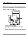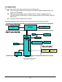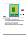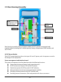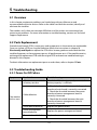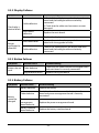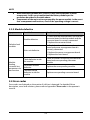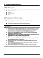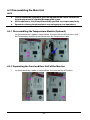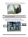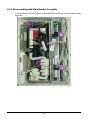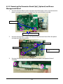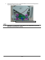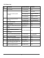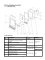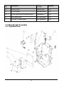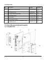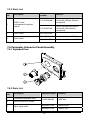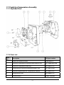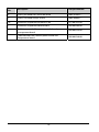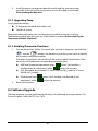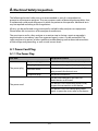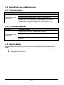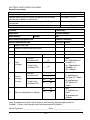
1
Vital Signs Monitor Service Manual Intellectual Property Statement SHENZHEN MINDRAY BIO-MEDICAL ELECTRONICS CO., LTD. (hereinafter called Mindray) owns the intellectual property rights to this product and this manual. This manual may refer to information protected by copyrights or patents and does not convey any license under the patent rights of Mindray, nor the rights of others. Mindray does not assume any liability arising out of any infringements of patents or other rights of third parties. Mindray intends to maintain the contents of this manual as confidential information. Disclosure of the information in this manual in any manner whatsoever without the written permission of Mindray is strictly forbidden. Release, amendment, reproduction, distribution, rent, adaption and translation of this manual in any manner whatsoever without the written permission of Mindray is strictly forbidden. , , and are the registered trademarks or trademarks owned by Mindray in China and other countries. All other trademarks that appear in this manual are used only for editorial purposes without the intention of improperly using them. They are the property of their respective owners. Contents of this manual are subject to changes without prior notice. For this manual, the issued Date is November 2014 (Version 2.0). © Copyright 2013-2014 Shenzhen Mindray Bio-Medical Electronics Co., Ltd. All rights reserved. WARNING Federal Law (USA) restricts this device to sale by or on the order of a physician. NOTE This manual describes all features and options. The equipment may not have all of them. Contact Mindray service department for any questions. I Manufacturer’s Responsibility Contents of this manual are subject to changes without prior notice. All information contained in this manual is believed to be correct. Mindray is not liable for errors contained herein nor for incidental or consequential damages in connection with the furnishing, performance, or use of this manual. Mindray is responsible for the effects on safety, reliability and performance of this product, only if: all installation operations, expansions, changes, modifications and repairs of this product are conducted by Mindray authorized personnel; the electrical installation of the relevant room complies with the applicable national and local requirements; the product is used in accordance with the instructions for use. Warranty Mindray warrants that components within its products will be free from defects in workmanship and materials for a period of three years from the date of purchase except that disposable or one-time use products are warranted to be free from defects in workmanship and materials up to a date one year from the date of purchase or the date of first use, whichever is sooner. This warranty does not cover consumable items such as, but not limited to, batteries, external cables, and sensors. Mindray shall not be liable for any incidental, special, or consequential loss, damage, or expense directly or indirectly arising from the use of its products. Liability under this warranty and the buyer’s exclusive remedy under this warranty is limited to servicing or replacing the affected products, at Mindray’s option, at the factory or at an authorized distributor, for any product which shall under normal use and service appear to Mindray to have been defective in material or workmanship. Recommended preventative maintenance, as prescribed in the service manual, is the responsibility of the user and is not covered by this warranty. No agent, employee, or representative of Mindray has any authority to bind Mindray to any affirmation, representation, or warranty concerning its products, and any affirmation, representation or warranty made by any agent, employee, or representative shall not be enforceable by buyer or user. THIS WARRANTY IS EXPRESSLY IN LIEU OF, AND MINDRAY EXPRESSLY DISCLAIMS, ANY OTHER EXPRESS OR IMPLIED WARRANTIES, INCLUDING ANY IMPLIED WARRANTY OF MERCHANTABILITY, NON-INFRINGEMENT, OR FITNESS FOR A PARTICULAR PURPOSE, AND OF ANY OTHER OBLIGATION ON THE PART OF MINDRAY. Damage to any product or parts through misuse, neglect, accident, or by affixing any II non-standard accessory attachments, or by any customer modification voids this warranty. Mindray makes no warranty whatsoever in regard to trade accessories, such being subject to the warranty of their respective manufacturers. A condition of this warranty is that the equipment or accessories which are claimed to be defective be returned when authorized, freight prepaid to Mindray DS USA, Inc., Mahwah, New Jersey 07430 or its authorized representative. Mindray shall not have any responsibility in the event of loss or damage in transit. Exemptions Mindray's obligation or liability under this warranty does not include any transportation or other charges or liability for direct, indirect or consequential damages or delay resulting from the improper use or application of the product or the use of parts or accessories not approved by Mindray or repairs by people other than Mindray authorized personnel. This warranty does not extend to: Malfunction or damage caused by improper use or man-made failure. Malfunction or damage caused by unstable or out-of-range power input. Malfunction or damage caused by force majeure events, such as (i) flood, fire and earthquake or other similar elements of nature or acts of God; (ii) riots, war, civil disorders, rebellions, or revolutions in any country; or (iii) any other cause beyond the reasonable control of Mindray. Malfunction or damage caused by improper operation or repair by unqualified or unauthorized service people. Malfunction of the instrument or part whose serial number is not legible. Others not caused by instrument or part itself. III Contact Information Manufacturer: Shenzhen Mindray Bio-Medical Electronics Co., Ltd. Address: Mindray Building, Keji 12th Road South, Hi-tech Industrial Park, Nanshan, Shenzhen 518057 P.R. China Tel: +86 755 81888998 Fax: +86 755 26582680 Website: www.mindray.com Distributor: Mindray DS USA, Inc. Address: 800 MacArthur Boulevard Mahwah, New Jersey 07430 USA Tel: 1.800.288.2121, 1.201.995.8000 Website: www.mindray.com IV Preface Manual Purpose This manual provides detailed information about the assembling, dissembling, testing and troubleshooting of the equipment to support effective troubleshooting and repair. It is not intended to be a comprehensive, in-depth explanation of the product architecture or technical implementation. Observance of the manual is a prerequisite for proper equipment maintenance and prevents equipment damage and personnel injury. Intended Audience This manual is for biomedical engineers, authorized technicians or service representatives responsible for troubleshooting, repairing and maintaining the equipment. V FOR YOUR NOTES VI Contents 1 Introduction ..............................................................................................................1-1 1.1 Manual Information .................................................................................................................1-1 1.2 Safety Information....................................................................................................................1-1 1.2.1 Warnings .........................................................................................................................1-2 1.2.2 Cautions ..........................................................................................................................1-2 1.2.3 Notes ................................................................................................................................1-2 1.3 Equipment Symbols ................................................................................................................1-3 2 Theory of Operation .................................................................................................2-1 2.1 Overview ......................................................................................................................................2-1 2.2 Connectors for Peripheral Devices .....................................................................................2-1 2.3 Main Unit .....................................................................................................................................2-2 2.4 Front Housing Assembly ........................................................................................................2-3 2.5 Rear Housing Assembly ..........................................................................................................2-4 2.6 External Module ........................................................................................................................2-5 3 Equipment Installation ............................................................................................3-1 3.1 Unpacking the Equipment ....................................................................................................3-1 3.2 Preparation for Installation ...................................................................................................3-1 3.2.1 Preparation for Installation Site ..............................................................................3-1 3.2.2 Environmental Requirements .................................................................................3-1 3.2.3 Electrical Requirements ............................................................................................3-2 3.3 Equipment Installation ...........................................................................................................3-2 3.4 Preparation for Power on .......................................................................................................3-2 4 Testing and Maintenance .........................................................................................4-1 4.1 Introduction................................................................................................................................4-1 4.2 Performance Tests ....................................................................................................................4-2 4.2.1 Performance Test Frequencies ................................................................................4-2 4.2.2 Visual Inspection ..........................................................................................................4-2 4.2.3 SpO2 Test .........................................................................................................................4-2 4.2.4 NIBP Test .........................................................................................................................4-4 4.2.5 Temperature Test .........................................................................................................4-8 4.3 Electrical Safety and Other Tests .........................................................................................4-9 4.3.1 Electrical Safety and Other Test Frequencies.....................................................4-9 4.3.2 Electric safety tests ......................................................................................................4-9 4.3.3 Power-on Test................................................................................................................4-9 4.3.4 Battery Check ............................................................................................................. 4-10 4.4 Maintenance Mode ............................................................................................................... 4-10 1 4.4.1 Entering/Quitting Maintenance Mode............................................................. 4-10 4.4.2 Checking Version Information ............................................................................. 4-12 4.4.3 Restoring Factory Default Configuration ........................................................ 4-13 5 Troubleshooting ....................................................................................................... 5-1 5.1 Overview ..................................................................................................................................... 5-1 5.2 Parts Replacement ................................................................................................................... 5-1 5.3 Troubleshooting Guide .......................................................................................................... 5-1 5.3.1 Power On/Off Failure ................................................................................................. 5-1 5.3.2 Display Failures ............................................................................................................ 5-2 5.3.3 Button Failures ............................................................................................................. 5-2 5.3.4 Battery Failures............................................................................................................. 5-2 5.3.5 Module defective ........................................................................................................ 5-3 5.4 Error codes .................................................................................................................................. 5-3 6 Disassembly and Repair .......................................................................................... 6-1 6.1 Tools Required ........................................................................................................................... 6-1 6.2 Preparations for Disassembly .............................................................................................. 6-1 6.3 Disassembling the Main Unit ............................................................................................... 6-2 6.3.1 Disassembling the Temperature Module (Optional) ...................................... 6-2 6.3.2 Separating the Front and Rear Half of the Monitor ........................................ 6-2 6.3.3 Removing the Parameter Connector Panel Assembly................................... 6-3 6.3.4 Disassembling the Main Bracket Assembly ....................................................... 6-4 6.3.5 Removing the Parameter Board (SpO2 Optional) and Power Management Board .......................................................................................................................................... 6-5 6.3.6 Disassembling Pumps and Valves ......................................................................... 6-6 6.3.7 Disassembling AC/DC Power Board and Battery Converter Board ........... 6-6 6.4 Disassembling the Front Housing Assembly ................................................................. 6-7 6.4.1 Removing the Main Board ....................................................................................... 6-7 6.4.2 Removing the Display ............................................................................................... 6-8 6.4.3 Removing the Keypad ............................................................................................... 6-8 6.5 Disassembling the Temperature Module (Optional) ................................................... 6-9 6.5.1 Removing the Temperature Module PCBA and Temperature Module Power Board PCBA .............................................................................................................................. 6-9 6.5.2 Disassembling the Temperature On-Position Detection Board PCBA ..... 6-9 7 Parts .......................................................................................................................... 7-1 7.1 Introduction ............................................................................................................................... 7-1 7.2 Main Unit ..................................................................................................................................... 7-1 7.2.1 Exploded View .............................................................................................................. 7-1 7.2.2 Parts List ......................................................................................................................... 7-2 7.3 Front Housing Assembly........................................................................................................ 7-3 7.3.1 Exploded View .............................................................................................................. 7-3 2 7.3.2 Parts List ..........................................................................................................................7-3 7.4 Main Bracket Assembly ..........................................................................................................7-4 7.4.1 Exploded View ..............................................................................................................7-4 7.4.2 Parts List ..........................................................................................................................7-5 7.5 Power Management Board Assembly ...............................................................................7-5 7.5.1 Exploded View ..............................................................................................................7-5 7.5.2 Parts List ..........................................................................................................................7-6 7.6 Parameter Connector Panel Assembly..............................................................................7-6 7.6.1 Exploded View ..............................................................................................................7-6 7.6.2 Parts List ..........................................................................................................................7-6 7.7 Predictive Temperature Assembly ......................................................................................7-7 7.7.1 Exploded View ..............................................................................................................7-7 7.7.2 Parts List ..........................................................................................................................7-7 8 Hardware and Software Upgrade ...........................................................................8-1 8.1 Hardware Upgrade ...................................................................................................................8-1 8.1.1 Upgrade Package ........................................................................................................8-1 8.1.2 Upgrading Parameter Modules ..............................................................................8-1 8.1.3 Upgrading Temp ..........................................................................................................8-2 8.1.4 Enabling Parameter Functions ...............................................................................8-2 8.2 Software Upgrade ....................................................................................................................8-2 A Electrical Safety Inspection .................................................................................... A-1 A.1 Power Cord Plug ..................................................................................................................... A-1 A.2 Device Enclosure and Accessories ................................................................................... A-2 A.3 Device Labeling ...................................................................................................................... A-2 3 FOR YOUR NOTES 4 1 Introduction 1.1 Manual Information A detailed revision history of this manual is recorded in the table below: Version Revision History 1.0 New 2.0 Modify Temperature module test method, update parts list 1.2 Safety Information WARNING Indicates a potential hazard or unsafe practice that, if not avoided, will result in death or serious injury. CAUTION Indicates a potential hazard or unsafe practice that, if not avoided, could result in minor personal injury or product/property damage. NOTE Provides application tips or other useful information to ensure that you get the most from your product. 1-1 1.2.1 Warnings WARNING All installation operations, expansions, changes, modifications and repairs of this product are conducted by Mindray authorized personnel. There is high voltage inside the equipment. Never disassemble the equipment before it is disconnected from the AC power source or the battery. When you disassemble/reassemble a parameter module, a patient leakage current test must be performed before it is used again for monitoring. The equipment must be connected to a properly installed power outlet with protective earth contacts only. If the installation does not provide for a protective earth conductor, disconnect it from the power line and operate it on battery power, if possible. Disposal of the packaging material should observe the applicable waste control regulations and keeping it out of children’s reach. 1.2.2 Cautions CAUTION Make sure that no electromagnetic radiation interferes with the performance of the equipment when preparing to carry out performance tests. Mobile phone, X-ray equipment or MRI devices are a possible source of interference as they may emit higher levels of electromagnetic radiation. Before connecting the receiver to the power line, check that the voltage and frequency ratings of the power line are the same as those indicated on the unit’s label or in this manual. Protect the equipment from damage caused by drop, impact, strong vibration or other mechanical force during servicing. 1.2.3 Notes NOTE Refer to operator’s manual for detailed operation and other information. 1-2 1.3 Equipment Symbols Some symbols may not appear on your equipment. Caution Neonate On/Off for a part of equipment Pediatric Clear key Adult Alternating current Equipotentiality Battery indicator Input/Output DEFIBRILLATION –PROOF TYPE CF APPLIED PART DATE OF MANUAFACTURE NIBP Start/Stop key MANUFACTURER Protection against fluid ingress Insertion Direction Serial number No alarming system Refer to instruction manual/ booklet Atmospheric pressure limitation Temperature limit Humidity limitation AUTHORISED REPRESENTATIVE IN THE EUROPEAN COMMUNITY CATALOGUE NUMBER Interference may occur in the vicinity of equipment marked with this symbol 1-3 The product bears CE mark indicating its conformity with the provisions of the Council Directive 93/42/EEC concerning medical devices and fulfills the essential requirements of Annex I of this directive. The following definition of the WEEE label applies to EU member states only. This symbol indicates that this product should not be treated as household waste. By ensuring that this product is disposed of correctly, you will help prevent bringing potential negative consequences to the environment and human health. For more detailed information with regard to returning and recycling this product, please consult the distributor from whom you purchased it. * For system products, this label may be attached to the main unit only. The presence of this label indicates the machine was certified by ETL with the statement: Conforms to AAMI Std. ES 60601-1, IEC Std. 60601-1-6, IEC Std. 80601-2-30, ISO Std. 80601-2-56, ISO Std. 80601-2-61. Certified to CSA Std. C22.2 NO. 60601-1, NO. 60601-1-6, NO. 80601-2-30, NO. 80601-2-56, NO. 80601-2-61. 1-4 2 Theory of Operation 2.1 Overview The monitor is intended for spot-check monitoring physiologic parameters, including SpO2, Pulse Rate, NIBP and Temperature, on adult, pediatric, and neonatal patients in healthcare facilities by clinical physicians or appropriate medical staff under the direction of physicians. 2.2 Connectors for Peripheral Devices 1 2 3 1. 2. 3. Input/Output connector (RS-232 connector) This connector is used for software upgrade and DIAP communication. AC power input Equipotential grounding terminal: When the equipment and other devices are to be used together, their equipotential grounding terminals should be connected together to eliminate the potential difference between them. 2-1 2.3 Main Unit The main unit of the vital signs monitor consists of three parts: Front housing assembly, consisting of main board, segment-code display, and Power On/Off keypad; Rear housing assembly: power module (AC/DC), power management and interface board (including SpO2 isolation power), battery, NIBP module, and SpO2 board; and, External module: Temperature module. The following figure shows the main unit architecture of the vital signs monitor. Front Housing Assembly Segment-code display Power On/Off keypad (indicator) Main board Rear Housing Assembly Pump Power management and interface board SpO2 isolation power 2600mAh battery NIBP connector NIBP module SpO2 board SpO2 receptacle External module Temperature module 15V AC-DC power module AC-IN External connector RS232 port (for software upgrade and DIAP communications.) 2-2 Temperature probe 2.4 Front Housing Assembly Main Board Keypad Main Board The main board is the control center of the equipment. It provides communication and display functions, including: Communication with SpO2 board, and NIBP module through serial ports, starting parameter measurement, and reading measured results; Communication with Predictive temperature module through serial ports; Communication with power management board through serial ports; Extending an RS232 serial port; Control over the Segment-code LCD display through I2C; Providing backlight drive for segment-code display; Recognition of keypad actions, and providing corresponding response; Control over the beeper through IO port; and, Providing 24 hour timing via the internal real time clock. Keypad The keypad contains the power switch, function keys and AC Battery indicator etc. 2-3 2.5 Rear Housing Assembly Power management and interface board AC/DC power module SpO2 board Battery compartment NIBP module Rear housing assembly consists of power module (AC/DC), power management and interface board (including SpO2 isolation power), battery compartment, NIBP module, and SpO2 board. AC/DC Power Module The AC/DC power board transforms the input AC into DC power, and is the power source for all voltages in the equipment. Power management and interface board The power management interface board provides the following functions: Charge and discharge of battery and charge detection; DC/DC conversion: outputs 12V and 5V DC power; Control over power On/Off key and AC, BAT indicator; Communication transmission among parameter modules; Providing isolation power for the SpO2 module; and, Providing external connectors, filter and protection for these connectors. 2-4 NIBP Module The NIBP module consists of blood pressure measurement board and pump and valve assembly, providing measurement acquisition of blood pressure data. The main functions of the NIBP module are: NIBP measurement; and, Data exchange with the main board through the serial ports. SpO2 board The SpO2 board collects SpO2 signals, processes SpO2 algorithm and sends measurement results to the main board. The power management interface board provides isolation power for it. 2.6 External Module An external Temperature module can be mounted on the monitor. The independently developed Mindray Temperature module consists of an isolation power board, Temperature measurement board, and probes. The Temperature measurement board collects Temperature signals, processes algorithm and sends measurement results to the main board. 2-5 FOR YOUR NOTES 2-6 3 Equipment Installation 3.1 Unpacking the Equipment Open the package and remove the packing list. Check that all the articles included in the packing list are available and the quantity and specification are correct. Make sure that: All the optional parts purchased by the customer have been received. Notify Mindray North America if your order is not correct or is incomplete. In case of damage during transportation, keep the packing material and notify the Mindray North America immediately. Keep the packing material until all equipment is checked and accepted. 3.2 Preparation for Installation 3.2.1 Preparation for Installation Site 1. 2. Ensure that the site meets all safety, environmental and power requirements. Ensure that a network connector is available if the equipment is to be connected to network. 3.2.2 Environmental Requirements To avoid explosion hazard, do not use the equipment in the presence of flammable anesthetics, vapors or liquids. The environment where the equipment will be used should be reasonably free from vibration, dust and corrosive substances. If these conditions are not met, the system may not function normally. The environmental specification is as follows: Main Unit Item Temperature (℃) Relative humidity (noncondensing) Altitude (mmHg) Operating environment 0 to 40 (without Temperature module) 5 to 40 (with Temperature module) 15% to 95% 427.5 to 805.5 Storage environment -30 to 70 10% to 95% 120.0 to 805.5 NOTE The environmental specifications of unspecified parameters are the same as those of the main unit. 3-1 3.2.3 Electrical Requirements Check that the system cables, power cords, and power plugs are not damaged, and that the pins are not loose. In case of any damage, remove it from use. WARNING Use only properly grounded power outlets. Use the supplied power cord only! Voltage 100 to 240V AC Current 0.9 to 0.5A Frequency 50/60 Hz 3.3 Equipment Installation Follow the procedure below to install the equipment: 1. Ensure the main unit and all accessories are not damaged. 2. Install the battery (optional). For detailed operations, please refer to the operator’s manual of the vital signs monitor. 3. Connect AC power. 4. Connect the accessories. The vital signs monitor can be mounted on a wall bracket or on a trolley support. The wall bracket or trolley support can be ordered as an optional accessory. Each type of mounting bracket is delivered with a complete set of mounting hardware and instructions. For detailed installation information, please refer to Wall-mount Bracket Instructions for Use (PN: 0010-20-42933) and Rollstand Instructions for Use (PN: 0010-20-42934). CAUTION Use only Mindray supplied or approved mounting solutions. The mounting bracket should be installed by qualified service personnel. 3.4 Preparation for Power on 1. 2. 3. Before you start using the equipment, check for any mechanical damage and make sure that all external cables, plug-ins and accessories are properly connected. Plug the power cord into the AC power source. If you run the equipment on battery power, ensure that the battery is sufficiently charged. Press the button on the front panel to turn on the equipment. 3-2 4 Testing and Maintenance 4.1 Introduction The expected service life of the equipment is five years. To ensure the equipment always functions normally, qualified service personnel should perform regular inspection, maintenance and test. This chapter provides a checklist of the testing procedures for the equipment with recommended test equipment and frequency. The service personnel should perform the testing and maintenance procedures as required and use appropriate test equipment. The testing procedures provided in this chapter are intended to verify that the equipment meets the performance specifications. If the equipment or a module fails to perform as specified in any test, repairs or replacements must be done to correct the problem. If you have any questions, contact Mindray Technical Support. CAUTION All tests should be performed by qualified service personnel only. Service personnel should acquaint themselves with the test tools and make sure that test tools and cables are vailable. 4-1 4.2 Performance Tests Performance test are designed to ensure that measurement results are accurate. The following sections provide a list of performance and accuracy tests and their recommended frequencies. 4.2.1 Performance Test Frequencies Check/Maintenance Item Recommended Frequency Visual Inspection When first installed or reinstalled. SpO2 test Leakage test Accuracy test NIBP test NIBP overpressure test Temperature test 1. If the user suspects that the measurement is incorrect. 2. Following any repairs or replacement of relevant module. 3. Every two years. Note: Per year is recommended for NIBP leakage and accuracy tests.. 4.2.2 Visual Inspection Perform an overall inspection on the appearance of the equipment. The test is passed if the equipment has no obvious signs of damage. Follow these guidelines when inspecting the equipment: Carefully inspect the case, display screen, buttons, and knob for obvious signs of damage. Inspect all external connections for loose connectors, bent pins or frayed cables. Inspect all connectors on the equipment for loose connectors or bent pins. Make sure that safety labels and data plates on the equipment are clearly legible. 4.2.3 SpO2 Test Test Method 1 Required Tool: None Test Procedure: 1. Connect SpO2 sensor for adult to the SpO2 connector of the monitor. Press the 2. 3. 4. button to set the patient category to Adult ( ). Place the SpO2 sensor on your finger. Verify SpO2 Level and Pulse Rate are displayed. Remove the SpO2 sensor from your finger and verify the SpO2 sensor off icon is displayed 4-2 Measurement validation The SpO2 accuracy has been validated in human studies against arterial blood sample reference measured with a CO-oximeter. Pulse oximeter measurements are statistically distributed, and only about two-thirds of the measurements can be expected to fall within the specified accuracy compared to CO-oximeter measurements. NOTE The SpO2 simulator can only be used to verify that the pulse oximeter operates properly. It cannot be used to verify the accuracy of the pulse oximeter or the SpO2 sensor. To verify the accuracy, clinical tests are required. Test Method 2 Required Tool: SpO2 simulator, Index-2 recommended Test Procedures: 1. Connect the SpO2 sensor to the SpO2 simulator. 2. Selected the model and manufacturer of the SpO2 module to be tested on the simulator, and set the simulator as follows: SpO2 to 96% and Pulse Rate to 80 bmp. 3. Set the patient type to adult, pediatric and neonate respectively. Observe the monitor and make sure the displayed SpO2 and PR value fall in the following range. Manufacturer SpO2 Pulse Rate Nellcor 96% ± 2% (Adult, Pediatric) 96% ± 3% (Neonate) 80 ± 3 bpm Masimo 96% ± 2% (Adult, Pediatric) 96% ± 3% (Neonate) 80 ± 3 bpm 4-3 4.2.4 NIBP Test 4.2.4.1 Leakage Test NOTE Perform NIBP leakage test before any other NIBP test and calibration. Tools required: Adult NIBP Cuff NIBP Hose Cylinder Follow this procedure to perform the leakage test: 1. 2. 3. Press the button to set the patient category to adult ( ). Connect the NIBP cuff to the NIBP connector on the monitor. Apply the cuff to the cylinder as shown below. Cylinder Monitor Connector for NIBP cuff NIBP Hose Cuff 4. Start the monitor. Within 10 s after you hear a beep, press and hold the button to enter the Maintenance mode. 5. Press the button to enter the NIBP leakage test interface. In the PR parameter area, code 550 is displayed. 6. Press the button to start leakage test. The real-time pressure is displayed at the top of the screen. Pressing the button with test in progress will terminate the leakage test. 4-4 7. If When the NIBP leak test is completed, the cuff will deflate automatically. is displayed in the error code area, it indicates the NIBP leak test is passed and that is displayed, it indicates the system may have a leak. Check the system has no leak. If the tubing and connections for leakages. If you ensure that the tubing and connections are all correct, perform a leakage test again. If the problem persists, contact our Technical Support Department. You may also perform a manual leakage test: 1. Perform steps 1 - 4 as described in Section 0 . 2. Raise the pressure in the rigid vessel to 250 mmHg with the manometer bulb. Then, wait for 5 seconds to allow the pressure to stabilize. 3. Record the current pressure value, wait 60 seconds, then record the pressure again. 4. Compare the two pressure values and make sure the difference is 6 mmHg or less. 4.2.4.2 NIBP Accuracy Test Required Tool: T-shape connector Appropriate tubing Manometer bulb Rigid Vessel with volume 500±25 ml Reference manometer (calibrated, with accuracy equal to or better than 0.75 mmHg) Follow this procedure to perform the accuracy test: 1. Connect the equipment as shown below. Monitor Connector for NIBP cuff Standard sphygmomanometer Appropriate tubing Manometer bulb Rigid Vessel 4-5 2. Before inflation, vent manometer bulb to atmosphere and verify manometer reads 0 mmHg.. 3. Start the monitor. Within 10 s after you hear a beep, press and hold the button to display button to enter the Maintenance mode. Then press the the NIBP accuracy test interface. In the PR parameter area, the code 555 is displayed. 4. 5. 6. 7. 8. Press the button to start accuracy test. The real-time pressure is displayed at the top of the screen. button with the test in progress will terminate the current Pressing the accuracy test. An invalid value will be displayed at the top of the screen. Check the manometer values and the monitor values. Both should be 0 mmHg. Raise the pressure in the metal vessel to 50 mmHg with the manometer bulb. Then wait 10 seconds to allow the pressure to stabilize. Compare the manometer values with the monitor values. The difference between the manometer and displayed values should be ± 3 mmHg. If it is greater than ± 3 mmHg, contact Mindray Technical Support. Raise the pressure in the metal vessel to 200 mmHg with the manometer bulb. Then wait 10 seconds to allow the pressure to stabilize. Repeat step 7. If the difference between the manometer and displayed values is greater than 3 mmHg, contact our Technical Support Department. NOTE You can use an NIBP simulator to replace the manometer bulb and the reference manometer to perform the test. 4.2.4.3 NIBP Cuff Overpressure Test Required Tool: T-shape connector Appropriate tubing Manometer bulb Rigid Vessel with volume 500±25 ml Reference manometer (calibrated, with accuracy equal to or better than 0.75 mmHg) 4-6 Follow this procedure to perform the NIBP cuff overpressure test: 1. Perform steps 1 to 2 in the 4.2.4.2 NIBP Accuracy Test. 2. Start the monitor. Within 10 s after you hear a beep, press and hold the button to display button to enter the Maintenance mode. Then press the the NIBP cuff overpressure test interface. In the PR parameter area, the code 520 is displayed. 3. Check the manometer values and the monitor values. Both should be 0 mmHg. Press the button to set the patient category to adult ( ). 4. Raise the pressure in the metal vessel to 330 mmHg with the manometer bulb. Then wait 10 seconds to allow the pressure to stabilize. 5. Press the 6 7. Press the button to set the patient category to pediatric ( ). Raise the pressure in the metal vessel to 330 mmHg with the manometer bulb. Then wait 10 seconds to allow the pressure to stabilize. 8. Press the button to start the NIBP cuff overpressure test. button to start the NIBP cuff overpressure test. 9. Press the button to set the patient category to neonate ( ). 10. Raise the pressure in the metal vessel to 165 mmHg with the manometer bulb. Then wait 10 seconds to allow the pressure to stabilize. 11. Press the If button to start the NIBP cuff overpressure test. is displayed in the error code area, it indicates the NIBP cuff overpressure is displayed, the NIBP cuff overpressure test is failed. If the test is passed. If test is failed, contact Mindray our your service personnel. NOTE You can use an NIBP simulator to replace the manometer bulb and the reference manometer to perform the test. 4-7 4.2.5 Temperature Test Required Tool: Thermostatic oil tank(HART 7102 recommended) or Water Bath and Precision Thermometer for reference. Test procedure: 1. Set the temperature of the oil tank or water bath to 37°C and conduct the test after the temperature stabilizes. 2. Set temperature unit to °C. The monitor switches to from Predictive Mode to Monitor Mode when neither a measurement is taken nor the probe is not replaced in the probe well within 60 seconds after it has been withdrawn. 3. In Monitor Mode, remove the Temperature probe from the probe sheath, insert a probe cover, and place the probe into the oil tank or water bath. 4. Wait till the Temp value displayed on the monitor stabilizes. Verify that the displayed value is ±0.1°C of the oil bath thermostat setting or reference thermometer. Contact our Technical Support Department if the Temperature test fails. NOTE Due to the different application environment and the test object in vivo and vitro conditions, there is deviations in the measurement result. The maximum deviation of 2.5℃ may exist in predictive Temperature measurement by liquid bath techniques. 4-8 4.3 Electrical Safety and Other Tests 4.3.1 Electrical Safety and Other Test Frequencies Check/Maintenance Item Recommended Frequency 1. Following any repair or replacement. 2. If monitor is physically damaged. 3. Every two years. For details, refer to Appendix A Electrical Safety Inspection. 1. When first installed or reinstalled. 2. Following any repairs or replacement of any main unit parts. Electric safety tests Power-on test Functional test 1. When first installed. 2. Whenever a battery is replaced. Performance test Once per year or if the battery run time reduced significantly. Battery check 4.3.2 Electric safety tests For details about electric safety tests, refer to Appendix A Electrical Safety Inspection. 4.3.3 Power-on Test This test is to verify that the equipment can power up correctly. This test is passed if the equipment starts up by following this procedure: 1. Insert the battery in the battery compartment, and connect the equipment to the AC mains. The AC mains indicator and battery indicator light up. 2. 3. 4. button on the front panel to turn on the equipment. The work Press the status indicator lights up inside the Power button. The screen lights up. The main interface is displayed. Now the equipment is correctly started. 4-9 4.3.4 Battery Check Required Tool: None Functional Test 1. 2. 3. 4. If the equipment is installed with a battery, remove the battery first. Verify that the equipment works correctly when running powered form an AC source. Insert the battery per the procedures provided in the operator’s manual. Remove the AC power cord and verify that the equipment still works correctly. Performance Test Perform the test by referring to the Battery chapter in the operator’s manual and verify the operating time of the battery meets the product specification. 4.4 Maintenance Mode 4.4.1 Entering/Quitting Maintenance Mode 1. Start the monitor. Within 10 seconds after you hear a beep, press and hold the button to enter the Maintenance mode. 2. button to toggle among maintenance items, such as NIBP unit Press the setup, Temperature unit setup, system time setup, NIBP leakage test, NIBP accuracy test, version information, restoring factory configuration, work time information, screen brightness adjustment and DIAP communication setup. 3. Press and hold the button to power off the monitor. The settings take effect after the monitor restarts. Using Keys In different modes, the key functions vary: Mode Keys and Functions : Press this key to change patient category. : Start/stop NIBP measurements. Measurement Mode : Press to: Clear the parameter value displayed on the screen (such as NIBP, Temp value). Clear the error code. Clear NIBP cuff indicator. 4-10 Mode Keys and Functions Clear the flashing SpO2 sensor indicator. When a parameter label flashes due to the module failure, stop the flashing. Disable the Low Battery audio indicator. : Press and hold for above 2 seconds to enter Parameter Setup mode. : Parameter Setup Mode Press and hold for more than 2 seconds to return to Measurement mode. Press to toggle among the parameters. : Switch on/off pulse tone; toggle among Temp measurement sites. Maintenance Mode (Refer to section 3.7 Maintenance Mode in operators’ manual) : Press to toggle among maintenance items. NIBP Unit Setup : Toggle between mmHg and kPa. Temperature Unit Setup : Toggle between °C and °F. System Time Setup : Toggle among hour and minute digits. Maintenance Items : Add one number based on current value. NIBP Leakage Test (PR parameter area displays “550”) : Start/Stop leakage test. NIBP Accuracy Test (PR parameter area displays “555”) : Start/Stop accuracy test. NIBP Cuff Overpressure test (PR parameter area displays “520”) : Start NIBP cuff overpressure calibration. Software Version : View the version of each module. Factory Default Configuration (PR parameter area displays “000”) : Toggle between ON and OFF ON: Restore the factory default configuration OFF: Keep current configuration 4-11 Mode Keys and Functions Working Time Check the total working time. : Decrease screen brightness. Brightness Setup : Increase screen brightness. DIAP Communication Setup (PR parameter area displays “001”) : Toggle between 9600 and 19200 bps. 4.4.2 Checking Version Information 1. Entering Maintenance mode. 2. Press the 3. button to toggle version information. Press the The following information is displayed on the monitor: System software version; NIBP module version; SpO2 module version; Temperature module version; and Power management software version. button and switch to version information. Examples of codes are listed below: Version Screen display Indication of codes System software version “030 000” indicates version 03.00.00 NIBP module hardware version “540” indicates version 05.04.00 SpO2 module version “1210” indicates version 1.2.1.0 4-12 Temperature module version “502” indicates version 5.0.2 Power management software version “011” indicates version 01.01 4.4.3 Restoring Factory Default Configuration 1. Entering Maintenance mode. 2. Press the button and switch to restore factory default configuration interface. In the PR parameter area, code 000 is displayed. 3. Press the button to change settings. indicates that the current settings will be restored to the factory default configuration while indicates the current settings will be retained. The default settings are: NIBP unit: mmHg Temperature unit: ℃ Patient category: Adult Beat sound: On Temperature position: oral Brightness: 5 4-13 FOR YOUR NOTES 4-14 5 Troubleshooting 5.1 Overview In this chapter, equipment problems are listed along with possible causes and recommended corrective actions. Refer to the tables to check the monitor, identify and eliminate the troubles. The troubles we list here are common difficulties and the actions we recommend can correct most problems. For more information on troubleshooting, contact our Technical Support Department. 5.2 Parts Replacement Printed circuit boards (PCBs), major parts and components in the monitor are replaceable. Once you isolate a PCB you suspect defective, follow the instructions in chapter 6 Disassembly and Repair to replace the PCB with a known good one and check that the trouble disappears or the equipment passes all performance tests. If the trouble remains, exchange the replacement PCB with the original PCB and continue troubleshooting as directed in this chapter. To obtain information on replacement parts or order them, refer to chapter 7 Parts. 5.3 Troubleshooting Guide 5.3.1 Power On/Off Failure Symptoms Possible Cause Troubleshooting AC mains not connected or battery too low Check that AC mains is properly connected or battery capacity is sufficient. Cable defective 1. Check that the cable between the keypad board and main board is correctly connected. 2. Check that the cable between the power board and power management board is correctly connected. 3. Check that the cable between the main board and power management board is correctly connected. Power board defective Replace the power board. Power management board defective Replace the power management board. The main board failed. Replace the main board. The monitor fails to start. 5-1 5.3.2 Display Failures Symptoms Possible Cause Troubleshooting Cable defective 1. Check if the cable between the display and main board and the backlight cable are correctly connected. 2. Check that the cables and connectors are not damaged. Main board defective Replace the main board. Display defective Replace the display. Main board error Replace the main board, or upgrade the main board with the upgrade software. Cable defective Check if the cable between the display and main board and the backlight cable are correctly connected. The display is blank or black. Images overlapped or distorted 5.3.3 Button Failures Symptoms Possible Cause Troubleshooting Buttons do not work Cable defective Check that the cable between the keypad board and main board is correctly connected. Keypad board failure Replace the keypad board. 5.3.4 Battery Failures Symptoms Battery cannot be charged Possible Cause Troubleshooting Battery defective Replace the battery. Cable defective Check that the cable between the battery interface board and power management board is correctly connected. Power management board defective Replace the power management board. Battery interface board defective Replace the battery interface board. 5-2 NOTE When the battery module has a failure, it may cause problems to other components. In this case, troubleshoot the battery module per the procedure described in the table above. Components of the main unit are powered by the power module. In the event that a component malfunctions, check if the operating voltage is correct. 5.3.5 Module defective Symptoms Possible Cause Troubleshooting Module defective 1. Check that the cable between the external converter board inside the module and the converter board is correctly connected. 2. Replace the converter board. Main unit defective 1. Check that the cable between the main board and power management board is correctly connected. 2. Replace the power management board. 3. Replace the main board. Cable defective inside the module Check the cables connecting the converter board and corresponding parameter module. Parameter module defective Replace the corresponding module. Converter board defective inside the module Replace corresponding converter board. Failed to load modules Module loading succeeds but parameters do not function 5.4 Error codes Error codes are displayed on the monitor if a failure is detected. For detailed failure description, cause and solutions, please refer to Appendix C Error codes in the operator’s manual. 5-3 FOR YOUR NOTES 5-4 6 Disassembly and Repair 6.1 Tools Required To disassemble and replace the parts and components, the following tools may be required: Philips screwdrivers Tweezers Sharp nose pliers Clamp 6.2 Preparations for Disassembly Before disassembling the equipment, finish the following preparations: Stop monitoring, turn off the equipment, and disconnect all the accessories and peripheral devices. Disconnect the AC power source and remove the battery. WARNING Before disassembling the equipment, be sure to eliminate the static charges first. When disassembling the parts labeled with static-sensitive symbols, make sure you are wearing electrostatic discharge protection such as antistatic wristband or gloves to avoid damaging the equipment. Properly connect and route the cables and wires when reassembling the equipment to avoid short circuit. Select appropriate screws to assemble the equipment. If incorrect screws are tightened by force, the equipment may be damaged. Follow correct sequence to disassemble the equipment. Be sure to disconnect all the cables before disassembling any parts. Be sure not to damage any cables or connectors. Place the screws and parts from the same module together to facilitate reassembling. To reassemble the equipment, first assemble the assemblies, and then the main unit. Carefully route the cables. Ensure all gaskets and seals are correctly installed during reassembly. 6-1 6.3 Disassembling the Main Unit NOTE To disassemble the equipment, place the equipment on a work surface free from foreign material, avoiding damaging the screen. All the operations should be performed by qualified service personnel only. Operations relating to optional parts may not apply to your equipment. 6.3.1 Disassembling the Temperature Module (Optional) Lay the monitor on a table as shown below. Unscrew the two M3×6 screws, pull the Temperature module up, and disconnect the Temperature cable. 6.3.2 Separating the Front and Rear Half of the Monitor 1. Lay the monitor on a table as shown below. Unscrew the four M3 screws. 6-2 2. Stand the monitor and separate the front housing assembly and rear housing assembly with caution. Disconnect the cable between the main board and power management board and then remove the front panel. NOTE When reassembling the equipment, be sure to check if the front housing waterproof strip is correctly placed. 6.3.3 Removing the Parameter Connector Panel Assembly Lay the rear housing assembly on the table, disconnect the SpO2 cable and connector panel connecting tube, and then remove the parameter connector panel. SpO2 signal cable Parameter connector panel assembly Silicone tube 6-3 6.3.4 Disassembling the Main Bracket Assembly Unscrew the four PT3×8 screws as indicated below. Then remove the main bracket assembly. 6-4 6.3.5 Removing the Parameter Board (SpO2 Optional) and Power Management Board 1. Unscrew the two M3×6 screws and two external hexagon screws, and remove the power management board assembly from the main bracket assembly. 2 M3 screws 2 external hexagon screws 2. Unscrew the two M3×4 screws and remove the parameter board from the power management board assembly. 2 M3 screws Parameter Board Power management board 3. Unscrew the two M3×6 screws and remove the power management board assembly. 6-5 6.3.6 Disassembling Pumps and Valves 1. Cut the two cable ties and remove the NIBP pump. Cable tie 2. Unscrew the two M3×6 screws as indicated and remove the valve. 6.3.7 Disassembling AC/DC Power Board and Battery Converter Board 1. Unscrew the four M3×6 screws as indicated and remove the AC/DC power board. 6-6 2. Unscrew the two M3 nuts to remove the battery interface board. 6.4 Disassembling the Front Housing Assembly NOTE To disassemble the equipment, place the equipment on a work surface free from foreign material, avoiding damaging the screen. Remember to install the screen support pad properly during reassembly. Operations relating to optional parts may not apply to your equipment. 6.4.1 Removing the Main Board Disconnect the cable between the main board and keypad board. Unscrew the four M3×6 screws and remove the main board, as shown below: 6-7 6.4.2 Removing the Display Unscrew the four M3×8 screws as indicated below. Remove the display assembly. Then unscrew the four PT2×6 and remove the display. 4 M3 screws Display 4 PT2 screws 6.4.3 Removing the Keypad Unscrew the Two PT3×8 screws indicated below and remove the keypad. Keypad 6-8 6.5 Disassembling the Temperature Module (Optional) 6.5.1 Removing the Temperature Module PCBA and Temperature Module Power Board PCBA Unscrew the 2 M3 screws indicated below and remove the metal sheet. Disconnect the Temperature board cable and the cable between Temperature isolation power board and Temperature board. Unscrew the four M3×6 screws; you can remove the Temperature module PCBA. Then unscrew the three M3×6 screws, you can remove the Temperature module power board PCBA. Cable between the isolation power board and Temperature board Metal sheet Screw for metal sheet 3 screws Temperature board cable Temperature module power board PCBA Temperature module PCBA 4 screws 6.5.2 Disassembling the Temperature On-Position Detection Board PCBA 1. Unscrew the four M3×6 screws as indicated and remove the Temperature module housing. 6-9 2. Unscrew the four M2 screws as indicated below and remove the Temperature on-position detection board PCBA. Temperature on-position detection board PCBA NOTE Remember to assemble the silicon button for the Temperature on-position detection switch during reassembly. 6-10 7 Parts 7.1 Introduction This section contains the exploded views and parts lists of the main unit. It helps the engineer to identify the parts during disassembling the monitor and replacing the parts. This manual is based on the maximum configuration. Your equipment may not have same parts and the quantity of the screws or stacking sleeves etc. may be different with those included in the parts lists. NOTE The part number listed in the Parts List is only for checking the FRU part number which is also included in the Parts List. Please provide the FRU parts number if you want to purchase the spare parts. 7.2 Main Unit 7.2.1 Exploded View 7-1 7.2.2 Parts List Item No. Description FRU part number Remarks 1 Rear housing 115-018253-00 N/A 115-017686-00 NIBP only 115-017681-00 NIBP plus Masimo SpO2 115-017682-00 NIBP plus Nellcor SpO2 2 Parameter connector panel assembly Power management board assembly 115-018256-00 With Nellcor SpO2 115-018257-00 With Masimo SpO2 4 NIBP valve assembly 115-017679-00 N/A 5 ST3.3X8 screw 030-000338-00 N/A 6 Screw, Pan Head W/Washer Phillips M3X6 M04-004012--- N/A 7 Pump 8 Shock absorption cushion for pump 801-9261-00040-00 N/A / Fixing strip 9 Accutorr 3 front housing assembly 115-022920-00 front housing assembly FRU 10 Battery door assembly 115-018252-00 N/A 11 Predictive Temperature module 115-017687-00 N/A 12 Screw, pan head, Phillips M3X8 M04-000605--- N/A / Cable between NIBP module and power management board 009-003238-00 N/A / Cable between the main board and power management board 009-003248-00 N/A 3 7-2 7.3 Front Housing Assembly 7.3.1 Exploded View 7.3.2 Parts List Item No. Description 1 Waterproof strip for front and rear housing 2 Accutorr 3 Front housing 6 Display lens 3 Keypad PCBA 4 Keypad board cushion FRU part number Remarks 115-022919-00 front cover FRU 051-001358-00 N/A N/A 115-020467-00 5 Keypad board adjusting sleeve 7 Short poron cushion 8 Long poron cushion 9 Segment-code display N/A 115-018251-00 7-3 N/A Item No. Description FRU part number Remarks 10 Screw, PT2X6 M04-051003--- N/A 11 ST3.3X8 screw 030-000338-00 N/A 12 Screw, pan head cross recessed M3X6 M04-004012--- N/A 13 Main board PCBA 051-001363-00 N/A / Accutorr 3 silicon buttons 049-000606-00 N/A 7.4 Main Bracket Assembly 7.4.1 Exploded View 7-4 7.4.2 Parts List Item No. Description FRU part number Remarks 1 6301 battery interface PCBA 115-018254-00 With cable 2 Knob, Battery latch 0380-00-0593 N/A 3 AC input receptacle and cable 009-003241-00 N/A 4 Power board shield 047-010575-00 N/A 5 Power board 022-000125-00 N/A 7 Power board insulator 047-010364-00 N/A / Cable between the power management board and power board 009-003237-00 N/A 7.5 Power Management Board Assembly 7.5.1 Exploded View 7-5 7.5.2 Parts List Item No. 1 Description PCBA, Power management/interface board 2 SpO2 shield 3 SpO2 board FRU part number Remarks 115-018256-00 Power management board service kit (without Masimo receptacle) 115-018257-00 Power management board service kit (with Masimo receptacle) 047-010576-00 / 100-000106-00 Nellcor SpO2 board (MDU) 040-000109-01 SpO2 board, Masimo MS-2013 7.6 Parameter Connector Panel Assembly 7.6.1 Exploded View 7.6.2 Parts List Item No. Description 1 Parameter receptacle cover 3 NIBP connector assembly 2 SpO2 signal cable FRU part number Remarks 115-017686-00 NIBP only 009-003372-00 Masimo SpO2 009-003373-00 Nellcor SpO2 7-6 7.7 Predictive Temperature Assembly 7.7.1 Exploded View 7.7.2 Parts List Item No. Description FRU part number 1 Screw, Pan head w/washer M04-004012--- 2 Predictive Temperature module power board PCBA 801-6006-00043-00 3 Predictive Temperature housing 043-003327-01 4 Temperature on-position detection board PCBA 051-001419-00 5 External compartment for Temperature module 043-003312-01 6 Temperature cover 049-000547-01 7 Silicon buttons M09A-20-62064 7-7 Item No. Description FRU part number 8 Screw, pan head cross recessed M2X6 M04-051003--- 9 Screw, Flat Head Phillips, M3X6 M04-005005--- 10 Predictive Temperature module PCBA 051-001435-00 / Predictive Temperature board cable 009-003368-00 / Cable between the Temperature module and power management board 009-003239-00 / Cable between the isolation power board and Temperature board 009-003240-00 7-8 8 Hardware and Software Upgrade 8.1 Hardware Upgrade The vital signs monitor supports upgrade of NIBP, SpO2 and Temperature functions. 8.1.1 Upgrade Package Upgrade package Description of upgrade package PN of upgrade package SpO2 Masimo SpO2 upgrade kit 115-023200-00 Nellcor SpO2 upgrade kit 115-018267-00 Temp Temperature module 115-017687-00 Note: measurement accessories are not included in the above upgrade packages. 8.1.2 Upgrading Parameter Modules 8.1.2.1 Upgrading Nellcor SpO2 List of upgrade package: A Nellcor SpO2 board; and, A connector panel assembly of the same SpO2 board. 1. 2. 3. Disassemble the power management board and parameter connector panel assembly as described in section 6.3 Disassembling the Main Unit. Remove the SpO2 board from the disassembled power management board assembly as described in section 6.3.5Removing the Parameter Board (SpO2 Optional) and Power Management Board, and assemble the SpO2 board in the upgrade kit. Install the power management board assembly with the SpO2 board and the connector panel assembly in the service kit into the main unit as described in section 6.3 Disassembling the Main Unit. 8.1.2.2 Upgrading Masimo SpO2 List of upgrade package: A Power Management Board Assembly; and, A parameter connector panel assembly. 1. Remove the power management board assembly and connector panel assembly as described in section 6.3 Disassembling the Main Unit. 8-1 2. Install the power management board assembly and the connector panel assembly in the service kit into the main unit as described in section 6.3 Disassembling the Main Unit. 8.1.3 Upgrading Temp List of upgrade package: A Temperature module with cables; and, Two M3×6 screws. Remove the decorative cover from the Temperature module connector. Install the Temperature module onto the main unit as described in section 6.5 Disassembling the Temperature Module (Optional). 8.1.4 Enabling Parameter Functions 1. Turn on the monitor. Within 10 seconds after you hear a beep, press and hold the and the buttons simultaneously, and the system starts to identify the currently configured modules. The labels of parameters start to flash till the end of module identification. Then the results are displayed in corresponding parameter areas, 2. NIBP and Temperature parameter areas: means the contrary. configured on this equipment" while SpO2 parameter area: Number”2” means Masimo SpO2 module, “3” means Nellcor SpO2 module. PR parameter area: equipment" while Restart the monitor. means "this module is means "SpO2 module is configured on this means the contrary. 8.2 Software Upgrade Software upgrades must be performed by Mindray, NA authorized service personnel. Call Service Dispatch 1 800 288-2121 ext: 7875. 8-2 A Electrical Safety Inspection The following electrical safety tests are recommended as part of a comprehensive preventive maintenance program. They are a proven means of detecting abnormalities that, if undetected, could prove dangerous to either the patient or the operator. Additional tests may be required according to local regulations. All tests can be performed using commercially available safety analyzer test equipment. Please follow the instructions of the analyzer manufacturer. The consistent use of a safety analyzer as a routine step in closing a repair or upgrade is emphasized as a mandatory step if an approved agency status is to be maintained. The safety analyzer also proves to be an excellent troubleshooting tool to detect abnormalities of line voltage and grounding, as well as total current loads. A.1 Power Cord Plug A.1.1 The Power Plug Test Item The power plug Acceptance Criteria The power plug pins No broken or bent pin. No discolored pins. The plug body No physical damage to the plug body. The strain relief No physical damage to the strain relief. No plug warmth for device in use. The power plug No loose connections. No physical damage to the cord. No deterioration to the cord. The power cord For devices with detachable power cords, inspect the connection at the device. For devices with non-detachable power cords, inspect the strain relief at the device. A-1 A.2 Device Enclosure and Accessories A.2.1 Visual Inspection Test Item Acceptance Criteria No physical damage to the enclosure and accessories. The enclosure and accessories No physical damage to meters, switches, connectors, etc. No residue of fluid spillage (e.g., water, coffee, chemicals, etc.). No loose or missing parts (e.g., knobs, dials, terminals, etc.). A.2.2 Contextual Inspection Test Item Acceptance Criteria No unusual noises (e.g., a rattle inside the case). The enclosure and accessories No unusual smells (e.g., burning or smoky smells, particularly from ventilation holes). No taped notes that may suggest device deficiencies or operator concerns. A.3 Device Labeling Check the labels provided by the manufacturer or the healthcare facility are present and legible. Main unit label Integrated warning labels A-2 ELECTRICAL SAFETY INSPECTION FORM Overall assessment Scheduled inspection Unopened repair type Opened repair type, not replace the power part including transformer or patient circuit board Opened repair type, replace the power part including transformer Opened repair type, replace patient circuit board Test item: 1, 2, 3, 4, 5, 6, 7 Test item: 1, 2, 3 Test item: 1, 2, 3, 4 Test item: 1, 2, 3, 4, 5 Test item: 1, 2, 3, 4, 6, 7 Location: Technician: Equipment: Control Number: Manufacturer: Model: SN: Measurement equipment /SN: Date of Calibration: INSPECTION AND TESTING Pass/Fail 1 Power Cord Plug 2 Device Enclosure and Accessories 3 Device Labeling 4 Protective Earth Resistance Normal condition(NC) 5 6 Earth Leakage Patient Leakage Current Ω ____μA Single Fault condition(SFC) ____μA Normal condition(NC) BF: ____μA CF: ____μA BF: ____μA Single Fault condition(SFC) CF: ____μA BF: ____μA 7 Mains on Applied Part Leakage CF: ____μA Limit Max 0.2 Ω Max: NC: 300μA(refer to UL60601-1) * NC: 500μA(refer to IEC60601-1) * SFC: 1000μA Max: CF applied part: NC:10μA, SFC: 50μA BF applied part: NC:100μA, SFC: 500μA Max: CF applied part: 50μA BF applied part: 5000μA Note: The equipment which sell to America shall comply with the requirement of UL60601-1, others shall comply with the requirement of IEC60601-1. Name/ Signature: __________________________ Date: _____________________________ A-3 FOR YOUR NOTES A-4 PN: 046-005295-00 (2.0)