1
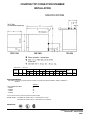
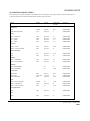
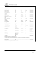
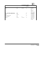
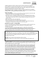
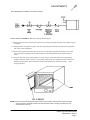
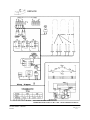
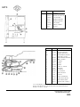
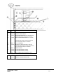
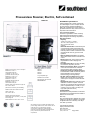
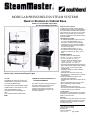
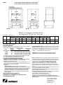
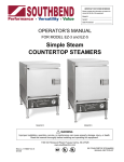
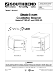
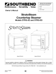
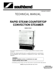
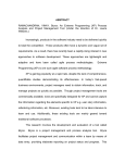
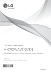
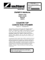
IMPORTANT
FOR FUTURE REFERENCE
Please complete this information and
retain this manual for the life of the
equipment.
MODEL #
SERIAL #
DATE PURCHASED
OWNER’S MANUAL
INSTALLTION
USER’S GUIDE
SERVICE
PARTS
COUNTER TOP
CONVECTION STEAMER
MODEL R-1: STEAMMASTER
These instructions should be read thoroughly before attempting installation.
Installation and Start Up should be performed by a qualified service
technician. The Manufacturer, Southbend (1100 Old Honeycutt Rd., FuquayVarina, North Carolina 27526), informs you that unless the installation
instructions for the above described Southbend product are followed and
performed by a qualified service technician, (a person experienced in and
knowledgeable concerning the installation of commercial gas and/or
electrical cooking equipment) then the terms and conditions of the
Manufacturer's Limited Warranty will be rendered void and no warranty of any
kind shall apply.
If the equipment has been changed, altered, modified or repaired by other than a
qualified service technician during or after the 12-month limited warranty period,
then the manufacturer shall not be liable for any incidental or consequential
damages to any person or to any property which may result from the use of the
equipment thereafter. Some States do not allow the exclusion or limitation of
incidental or consequential damages, so the above limitation or exclusion thereto
may not apply to you. In the event you have any questions concerning the
installation, use. care, or service of the product, write Customer Service
Department, Southbend, 1100 Old Honeycutt Rd., Fuquay-Varina, North
Carolina 27526.
WARNING: Improper installation, adjustment, alteration, service or
maintenance can cause property damage, injury or death. Read the
installation, operating and maintenance instructions thoroughly before
installing or servicing this equipment.
Congratulations! You have just purchased one of the finest pieces of heavy -duty, commercial cooking equipment
on the market today.
You will find that your new equipment, like all Southbend equipment, has been designed and manufactured to
some of the toughest standards in the industry — those of Southbend Corporation. Each piece of Southbend
equipment has been carefully engineered and designs have been verified through laboratory tests and field
installations in some of the more strenuous commercial cooking applications. With proper care and field
maintenance, you will experience years of reliable, trouble -free operation from your Southbend equipment. To get
the best results, it's important that you read this manual carefully.
TABLE OF CONTENTS:
SECTION ONE - INSTALLATION
Specifications ............................................................................................................................................1
Installation .................................................................................................................................................3
For Sectional Battery Assembly Instruction See ATTENTION INSTALLER MANUAL, Part No. 1165403/1
SECTION TWO - USER'S GUIDE
Warranty ...................................................................................................................................................1
Operation ..................................................................................................................................................2
Cooking Hints ...........................................................................................................................................6
Maintenance .............................................................................................................................................8
SECTION THREE – SERVICE
Adjustments ..............................................................................................................................................1
Service .....................................................................................................................................................6
Troubleshooting ........................................................................................................................................6
Schematic Drawings .................................................................................................................................9
SECTION FOUR – PARTS
Parts List ...................................................................................................................................................1
RETAIN THIS MANUAL FOR FUTURE REFERENCE.
INTENDED FOR COMMERCIAL USE ONLY. NOT FOR HOUSEHOLD USE.
WARNING-WARRANTY WILL BE VOID IF
A. SERVICE WORK IS PERFORMED BY OTHER THAN A QUALIFIED TECHNICIAN.
B. OTHER THAN GENUINE SOUTHBEND REPLACEMENT PARTS ARE INSTALLED.
FOR YOUR SAFETY
DO NOT STORE OR USE GASOLINE OR OTHER FLAMMABLE VAPORS AND LIQUIDS IN
THE VICINITY OF THIS OR ANY OTHER APPLIANCE.
KEEP AREA AROUND APPLIANCES FREE AND CLEAR FROM COMBUSTIBLES.
IN THE EVENT A GAS ODOR IS DETECTED, SHUT DOWN EQUIPMENT AT THE MAIN
SHUTOFF VALVE AND CONTACT THE LOCAL GAS COMPANY OR GAS SUPPLIER FOR
SERVICE.
COUNTER TOP CONVECTION STEAMER
INSTALLATION
SPECIFICATIONS
DIMENSIONS: ( ) = Millimeters
MODEL
Width
A
Width
B
DEPTH
DRAIN
WATER
ELECTRIC CONN.
C
0
E
F
G
H
J
K
L
STEAM
MASTER
16"
(406)
19"
(482)
24%"
(625)
28%"
(727)
2"
(51)
W
(38)
6%"
(158)
374"
(82)
9%"
(235)
8V7(216)
1"
(25)
CRATE SIZE
Cubic
Width Depth Heigh Volume
t
19"
30"
22"
7.25 cu. U.
(482) (762) (559) .20 cu. m.
Crated
Weight
90 lbs.
41kg.
UTILITY INFORMATION:
ELECTRIC: One electric connection required. Controls on all units and, elements 208/60/1, 240/60/1, 208/60/3, or
240/60/3.
TOTAL CONNECTED AMPS
208/60/1
208/60/3
240/60/1
240/60/3
208/240 V
9KW
44
25
38
22
'Circuit must be wired for maximum 9 KW at required voltage.
WATER USAGE: 0.12 gallons per minute at 45 p.s.i. water pressure in cavity.
0.16 gallons per minute at 45 p.s.i. water pressure in condenser.
APPROVALS:
COUNTER TOP CONVECTION STEAMER
SECTION ONE — INSTALLATION
PAGE1
INSTALLATION
GENERAL:
THE UNIT WHEN INSTALLED MUST BE ELECTRICALLY GROUNDED AND COMPLY
WITH LOCAL CODES, OR IN THE ABSENCE OF LOCAL CODES, WITH THE
NATIONAL ELECTRICAL CODE ANSI NFPA 70-1990.
CANADIAN INSTALLATION MUST COMPLY WITH CSA STANDARD C22.2 No. 0M1982 -General Requirements - Canadian Electrical Code, Part II. 109-M1981 - Commercial
Cooking Appliances
CLEARANCES:
Allow at least a four inch (4") 102 mm. clearance between the back of the unit and any wall
obstruction for proper ventilation of the unit, and room for plumbing and electrical connections.
Do not locate the STEAMMASTER adjacent to any high heat[producing piece of equipment,
such as a range top, griddle, fryer, etc., that could allow radiant heat to raise the exterior
temperature of the STEAMMASTER above 130T (54°C).
DO NOT MOUNT ABOVE OTHER COOKING EQUIPMENT.
WARNING:
THESE PROCEDURES MUST BE FOLLOWED BY QUALIFIED PERSONNEL OR
WARRANTY WILL BE VOIDED.
TO INSTALL:
1. Uncrate carefully. Report any hidden freight damage to the freight company immediately.
2. Do not remove any tags or labels until the unit is installed and working properly.
3. Set unit in place.
4. Counter Model — Set on non-flammable surface and shim to make level. Seal to counter top with
sealer such as G.E. or DOW Corning RTV type sealant. (Consult local code for exact
requirements.)
LEVELING:
Unit must be level to assure maximum performance. Improper leveling may void warranty.
WATER CONNECTION:
Connect cold water line, 1/4" (6 mm.) pipe. Water line pressure should be 30 psi (205 Kpa) minimum
— 60 psi (410 Kpa) maximum.
NOTE: Tb facilitate cleaning, plus allowing access to rear of unit, flexible connections are recommended.
WATER SPECIFICATION:
To meet warranty requirement, supply water must be as follows:
Pressure: 30 to 60 psi
Total dissolved solids (TDS) — 60 PPM
Hardness: 2 grains or 35 PPM
PH factor: 7.0 to 7.5
WATER LEVEL SWITCH FLOAT INSTALLATION:
See page 5 SERVICE.
COUNTER TOP CONVECTION
STEAMER SECTION ONE — INSTALLATION
Page 2
Litho in
U.S.A. 4-92
INSTALLATION
DRAIN LINE:
The drain line connection size from the unit is 1-1/4" NPT (32 mm). Position the unit near, but not on top of,
an open floor drain. DO NOT directly plumb to the unit unless you also install an "open funnel" downstream
of this connection in the drain system. Make the drain line from the unit to the air gap above the "open
funnel" as short as possible. There should be no horizontal piping between the unit and the air gap above the
"open funnel". The "open funnel" is intended to eliminate any water from entering the steamer because of a
blocked drain and it also prevents any back pressure within the steamer cavity. The unit must be free-venting
to atmosphere. Any connection that allows the build-up of back pressure in the unit such as a reduction in
pipe size to a line smaller than 1-1/4" or a 90 degree angle in the line prior to the "open funnel" drain
discharge point will void the warranty. This is a pressureless, free-venting steam cooker and will not operate
properly unless the drain line is short, at a steep angle, and open!
ELECTRICAL CONNECTION:
For proper connection of field wiring to terminal block, see Wiring Diagram, Section 3, Page 6. Be sure
that the input voltage and phase match the requirements shown on the serial plate located on the left rear
side of each piece of equipment.
NOTE: This unit has one power supply for controls and elements, as well as one (1) ground wire. A
POSITIVE GROUND CONNECTION IS ESSENTIAL.
DO NOT ALLOW ANY TAMPERING OR ADJUSTMENT OF ANY CONTROL OR WIRING. THE
UNIT IS FACTORY SET. ADJUSTMENT OF ANY INTERNAL COMPONENT OTHER THAN THE
FIELD TERMINAL BLOCK CAN VOID THE WARRANTY.
FINAL:
5. Open water valve to full open position.
CHECK:
a. Power to unit.
b. Water to unit.
c. Open drain.
Unit is now ready for initial start-up.
COUNTER TOP CONVECTION STEAMER
SECTION ONE — INSTALLATION
PAGE 3
INSTALLATION
STEAMMASTER STACKING INSTRUCTIONS:
1. Bolt spacer (Item 1) to bottom of top unit, using the 3/8" bolts holding the lower cover on. Cover
remains on.
2. Attach nipple (Item 2) to lower threads of drain "tee" at rear of top unit.
3. Place rubber sleeve (Item 4) on lower portion of just installed nipple (top unit).
4. Carefully lower top unit onto lower unit, lining up sleeve with top of vent pipe on lower unit. Secure
with clamps.
5. It is recommended to drill (2) 3/32" holes in each side through the spacer bracket holes and secure in
place with #10 sheet metal screws.
PERFORMANCE CHECK:
The following items should be checked before or within the first 30 days of operation by a qualified
service technician.
1. Check doors for proper alignment.
2. Check door gaskets for wear and sealing ability.
3. Check spray tubes or nozzles for cleanliness and/or leakage.
4. Check all gauges, timers, valves and switches for proper operation.
5. Visually check control compartment wiring for burned or loose connections.
6. Is user keeping compartment clean?
7. Check electrical load on elements, where applicable, for proper wattage.
8. Check hoses at clamped connections, it is particularly important to ensure that the hose connected to
front panel drain tube is securely attached.
COUNTER TOP CONVECTION STEAMER
SECTION ONE — INSTALLATION
PAGE 4
Litho in U.S.A.
4-92
COUNTER TOP CONVECTION
STEAMER
USER'S GUIDE
LIMITED WARRANTY
Southbend warrants that the equipment, as supplied by the factory to the original purchasers, is free from defects in materials and
workmanship. Should any part thereof become defective as a result of normal use within the period and limits defined below, then at
the option of Southbend such parts will be repaired or replaced by Southbend or its Authorized Service Agency. This warranty is
subject to the following conditions:
If upon inspection by Southbend or its Authorized Service Agency it is determined that this equipment has not been used in an
appropriate manner, has been modified, has not been properly maintained, or has been subject to misuse or misapplication, neglect,
abuse, accident, dam age during transit or delivery, fire, flood, riot or Act of God, then this warranty shall be void.
Specifically excluded under this warranty are claims relating to installation; examples are improper utility connections and improper
utilities supply. Claim s relating to normal care and maintenance are also excluded; examples are calibration of controls, and
adjustments to pilots and burners.
Equipment failure caused by inadequate water quality is not covered under warranty. WATER QUALITY must not exceed the
following limits: Total Dissolved Solids (TDS) - 60 PPM (Parts Per Million). Hardness - 2 Grains or 35 PPM, PH Factor
- 7.0 to 7.5. Water pressure 30 PSI minimum, 60 PSI maximum. Boiler maintenance is the responsibility of the owner and is not
covered by warranty.
This equipment is intended for commercial use only. Warranty is void if equipment is installed in other than commercial application.
Repairs under this warranty are to be performed only by a Southbend Authorized Service Agency. Southbend can not be responsible
for charges incurred from other than Authorized Southbend Agencies. THIS WARRANTY MUST BE SHOWN TO AN AUTHORIZED
SERVICE AGENCY WHEN REQUESTING IN-WARRANTY SERVICE WORK. THE AUTHORIZED SERVICE AGENCY MAY AT HIS
OPTION REQUIRE PROOF OF PURCHASE. This warranty does not cover services performed at overtime or premium labor rates nor
does Southbend assume any liability for extended delays in replacing or repairing any items in the equipment beyond the control of
Southbend. "Southbend shall not b e liable for consequential or special damages of any nature that may arise in connection with such
product or part." Should service be required at times which normally involve overtime or premium labor rates, the owner shall be
charged for the difference between normal service rates and such premium rates. In all circumstances, a maximum of one hundred
miles in travel and two and one half hours (2.5) travel time shall be allowable. In all cases the closest Southbend Authorized Agency
must be used. The actual warranty time periods and exceptions are as follows:
This warranty only covers product shipped into the 48 contiguous United States and Hawaii, one year labor, one year parts effective
from the date of original purchase. There will be no labor coverage for equipment located on any island not connected by roadway to
the mainland. Exceptions to standard warranty, effective within above limitations:
Glass Windows, Door Gaskets, Rubber Seals, Light Bulbs, Ceramic Bricks, Sight Glasses, Cathodic Descalers or Anodes
................................... 90 days material and labor
Stainless Steel Fry Pot.........................4 years extended material warranty on fry pot only — no labor
Stainless Steel Open Top Burners ...............4 years extended material warranty on burners only — no labor
Pressure Steam Boiler Shell ................ Prorated 4 years extended warranty on boiler shell only — no labor
Boiler shells which have not been properly maintained will not be covered by warranty. In all cases
parts covered by a five year warranty will be shipped FOB the factory after the first year. Our warranty on all replacement parts which
are replaced in the field by our Authorized Service Agencies will be limited to three months on labor, six months on materials (parts)
effective from the date of installation. See LIMITED WARRANTY
- REPLACEMENT PARTS for conditions and limitations.
If the equipment has been changed, altered, modified or repaired by other than a qualified service technician during
or after the one year limited warranty period, then the manufacturer shall not be liable for any damages to any person
or to any property which may result from the use of the equipment thereafter.
"THE FOREGOING WARRANTY IS IN LIEU OF ANY AND ALL OTHER WARRANTIES EXPRESSED OR IMPLIED
INCLUDING ANY IMPLIED WARRANTY OF MERCHANTABILITY OR FITNESS, AND CONSTITUTES THE ENTIRE
LIABILITY OF SOUTHBEND. IN NO EVENT DOES THE LIMITED WARRANTY EXTEND BEYOND THE DURATION
OF ONE YEAR FROM THE EFFECTIVE DATE OF SAID WARRANTY."
COUNTER TOP CONVECTION STEAMER
SECTION TWO — USER'S GUIDE
PAGE 1
OPERATION
THEORY OF OPERATION:
Compared to other steam cookers with complicated boilers, the STEAMMASTER is a very simple
machine. Immersion elements are installed on the left side of the cavity and when water covers the
elements, water starts to boil and turn to steam. There is no pressure in this unit.
All equipment must be installed correctly to ensure proper operation and reliable service. Installation
instructions must be followed by a qualified technician.
Before you turn the unit on, be sure that you have: POWER to unit, WATER to unit, and OPEN DRAIN.
NOTE: Your STEAMMASTER must be thoroughly cleaned every day.
CAUTION: DO NOT USE ANY CORROSIVE CLEANER. USE ONIV CLEANERS APPROVED
FOR STAINLESS STEEL.
Before starting the unit, review the following:
A. Be sure overflow pipe in back right hand corner of the cooking compartment is in position.
B. Be sure the drain outlet is not blocked in any way. (The STEAMMASTER drain line must be free
venting.)
C. Be sure the pan supports and steam deflector are well secured.
CONTROL INSTRUCTIONS:
1. For manual operation, press right-hand rocker switch to "MANUAL" and the light will turn on. The
unit is now in operation and will be generating steam in a few minutes (approximately 9 minutes
from a cold start).
2. For timed operation, press right-hand rocker switch to "
." Set timer by positioning knob
pointer to desired time marking. When time elanses buzzer will sound. Buzzer may be shut off by
opening door, moving selector switch to "
," shutting unit off, resetting to a new time or
turning knob counterclockwise to the Hold/Off position (counterclockwise past "0" time).
3. To restart timer, set to new time marking.
NOTE: Timer is an audible time reminder only. It does not control cook time or shut off elements.
HEATING ELEMENTS REMAIN ON.
4. The STEAMMASTER is designed to accept standard 12" x 20" pans (305 x 508 mm.). Fractional
size pans can be used as well with optional stainless steel perforated shelf.
INSTRUCTIONS FOR TURNING OFF BUZZER:
The STEAMMASTER is supplied with a continuous ring buzzer. This buzzer is activated automatically
in the automatic mode of operation when the cooking cycle is complete. This buzzer can be turned off by:
1. Reset timer to begin a new time cycle.
2. Set the three position rocker switch to
or to off position.
3. Open the door of the unit
4. Turn knob counterclockwise past "0" time.
COUNTER TOP CONVECTION STEAMER
SECTION TWO — USER'S GUIDE
PAGE 2
Litho in U.S.A.
4-92
COOKING HINTS
SUGGESTED COOKING TIMES:
Timer settings are for general guidance only. Differences in food quality, size, shape, freshness, load size and degree of
cook desired must be considered and adjustments made in time if necessary.
Product
Weight
Portions
Cooking Time
(minutes)
Pan Used
Fresh
3'/2 Ibs.
14(40Z.)
8-10
Full/Perforated
Frozen Spears (Thawed)
5 IDS.
20 (4 oz.)
9
Full/Perforated
Green — Frozen, Cut
5 Ibs.
20 (4 oz.)
12
Full/Perforated
Green — Fresh
Wax — Frozen
Lima — Frozen
5 Ibs.
5 Ibs.
5 Ibs.
20 (4 oz.)
20 (4 oz.)
20 (4 oz.)
15-17
13
10
Full/Perforated
Full/Perforated
Full/Perforated
Spears — Fresh
4 Ibs.
16(4oz.)
10-12
Full/Perforated
Spears — Frozen (Thawed)
5 Ibs.
20 (4 oz.)
8
Full/Perforated
Fresh
5 Ib.
20 (4 oz.)
15-17
Full/Perforated
Fresh
5 Ibs.
20 (4 oz.)
13
Full/Perforated
Frozen — Whole Baby
5 Ibs.
20 (4 oz.)
12
Full/Perforated
Fresh — V4-lnch Bias Cut
5 Ibs.
20 (4 oz.)
12
Full/Perforated
Green, Cut Into Wedges
24
15
Full/Perforated
Red, Cut Into Wedges
16
18-20
Full/Perforated
ASPARAGUS
BEANS
BROCCOLI
BRUSSEL SPROUTS
CARROTS
CABBAGE
CAULIFLOWER
Fresh, Whole
2 Ibs.
8 (4 oz.)
9-10
Full/Perforated
Fresh, Whole
Frozen, Flowerettes
2 Ibs. 12oz.
5 Ibs.
11 (4 oz.)
20 (4 oz.)
15
10-12
Full/Perforated
Full/Perforated
Fresh — Cob, 4-5 Inch Ears
5V2 Ibs.
15
13-15
Full/Perforated
Frozen — Whole Kernel
Frozen — Cob, 6 Inch Ears
5 Ibs.
9 Ibs.
20 (4 oz.)
14
8
12-14
Full/Perforated
Full/Perforated
5 Ibs.
20 (4 oz.)
12
Full/Perforated
5 Ibs.
20 (4 oz.)
8
Full/Perforated
CORN
MIXED VEGETABLES
Frozen
PEAS
Frozen
COUNTER TOP CONVECTION STEAMER
SECTION TWO — USER'S GUIDE
PAGE 3
COOKING HINTS
Product
Weight
Portions
Cooking Time
(minutes)
Pan Used
Red Bliss — Whole
7lbs.
28
35
Full/Perforated
Russetts — Whole
8!bs.
20
23-25
Full/Perforated
Russetts — Peeled
5lbs.
12
20
Full/Perforated
Russetts 1-Inch Cubes
5lbs.
20 (4 oz.)
17
Full/Perforated
Fresh, Leaf
2Vz Ibs.
10(4oz.)
5
Full/Perforated
Frozen, Chopped
6lbs.
24 (4 02.)
35
Full/Perforated
5lbs.
20 (4 oz.)
6-8
Full/Perforated
12 Ibs.
12
15-16
V2 Perforated
Corned Beef
6% Ibs.
18(6oz.)
2 hours
Full
Hot Dogs, Thawed
5lbs.
40 (2 OZ.)
5
Full/Perforated
Hot Dogs, Frozen
5lbs.
40 (2 oz.)
10
Full/Perforated
Boneless Chicken Breast
4V2 IbS.
12 (6 oz.)
15
Full/Perforated
Tamales, Frozen
3 Ibs.
12(4oz.)
20
Full/Perforated
Tortilla, Frozen 8-Inch
4 Tortillas
4
45 Seconds
Half/Perforated
Beef Ravioli, Frozen
48 Ravioli
8
5-6
Full/Perforated
In Perforated
POTATOES
SPINACH
ZUCCHINI
Fresh — Slices y4-lnch Thick
EGGS
Large — Hard Cooked
MEATS
FOWL
(1 Ib. 8 oz.)
Elbow Macaroni
2 Ibs. Uncooked
32 (2 oz.)
7
Spaghetti
2 Ibs. Uncooked
32 (2 oz.)
14
Egg Noodles
2Ibs. Uncooked
32 (2 oz.)
10
Converted Rice
2 Ibs.
Pan Nested
in 4-Inch
Full/Perforated
25
Full/Perforated
2Vz Qts. Water
+ Oil & Salt
Navy Beans
2 Ibs.
Full/Perforated
Place beans in pan & cover w/3-quarts hot tap water.
Steam for 2 minutes; remove fromsteamer & cover for 1 hour. Remove cover & place back in steamer for 40
minutes.
Black Eyed Peas
2 Ibs.
Full/Perforated
Place peas in pan & cover w/3-quarts hot tap water. Steam for 2 minutes; remove from steamer & cover for 1
hour. Remove cover & place back in steamer for 35 minutes.
COUNTER TOP CONVECTION STEAMER
SECTIO N TWO — USER'S GUIDE
PAGE 4
Litho in U.S.A.
4-92
COOKING HINTS
Product
Weight
Portions
Cooking Time
(minutes)
Pan Used
Oysters
5 Ibs.
16 Count
12
Perforated
Pan
Nested in a
Full Pan
2V2-lnch Deep
Shrimp, Fresh, Medium, Heads Removed
5 Ibs.
6-7
Full/Perforated
Shrimp, Frozen, Large, Peeled & Devined
5 Ibs.
8
Full/Perforated
Lobster
13/4 Ibs.
8
Full/Perforated
Alaskan King Crab Legs
1 Ib.
4-5
Full/Perforated
Cherrystone Clams
5 Ibs.
12
7
Full/Perforated
Fish Fillets
7V2 Ibs.
12 (10 oz.)
18
Full/Perforated
Nested in Full
Hotel Pan
COUNTER TOP CONVETION STEAMER
SECTION TWO — USER'S GUIDE
PAGE 5
COOKING HINTS
END USER TIPS:
Schedule cooking of fresh vegetables so that they will be served soon after they are cooked. If it is
necessary to prepare them in advance, they can be plunged into cold water, drained thoroughly and held
under refrigeration until needed for service.
Five pounds of cold cooked vegetables can be reheated in the steamer in 5 to 10 minutes, depending upon
the variety.
Adding salt to the water for eggs cooked in the shell makes the cooking water more efficient and faster at
its job. If the egg cracks, the "white is cooked at the crack and is sealed right away.
To avoid the dreaded green yolk (which is a deposit of iron sulfide) chill the eggs immediately after
removing from the steamer by plunging them into a cold water bath (preferably containing ice).
A quick and easy way to cook eggs for a salad mixture is to crack them directly into a solid steam table
pan which has been lightly coated with salad oil. Do not mix. Steam until they are hard cooked. Remove
and chop as you would for egg salad. The job of peeling has been eliminated.
Transfer steamed hot chicken to deep pan, cover with Cacciatore Sauce and finish in oven. Bake 20 to 30
minutes. May be held on steam table.
After cooking, chicken may be browned in Infra-Red or Radiant Broiler. Brush with melted margarine
mixed with salad oil to give a golden brown color.
Use juice saved from steamed chicken to make soups, sauces, or casserole dishes.
Chicken may be steamed in advance and held under refrigeration for next day's use. Be sure to bring
product back to 180 °F before serving.
Save the juice from the corned beef. After the cabbage has been steamed, place it in a solid pan and add
the juice for flavoring and holding on a steam table.
Steaming brisket in the STEAMMASTER is a definite time saver. Boiling in water takes 40 to 50
minutes per pound. Using the STEAMMASTER can save 50% in cooking time.
Cabbage when steamed, retains its color and wedge identity. It will not break apart as it does when boiled
in an open pot.
When removing items prepared in a perforated pan, put a solid pan underneath the perforated pan to hold
the pan of cooked food. This will prevent dripping on the floor.
The STEAMMASTER is designed to accept standard 12 x 20 pans. Fractional size pans can be used as
well with the optional perforated shelf.
For stirring, the pan does not have to be removed from the steamer. Pull pan 1/3 way out of the cavity
and the entire surface is accessible.
The door may be opened at any time during operation to remove or add food.
COUNTER TOP CONVECTION STEAMER
SECTION TWO — USER'S GUIDE
PAGE 6
Litho in U.S.A.
4-92
MAINTENANCE
Southbend equipment is sturdily constructed of the best quality materials and is designed to
provide durable service when treated with ordinary care. To expect the best performance, your
equipment must be maintained in good condition and cleaned daily. Naturally, the periods for this
care and cleaning depend on the amount and degree of usage.
Following daily and periodic maintenance procedures will enhance long-life for your equipment.
Climatic conditions - salt air - seasonings - water quality - may require more thorough and frequent
cleaning or the life of the equipment could be adversely affected.
DAILY CLEANING
• Remove the pan supports, well cover, and overflow pipe. Wash seperately in a sink with a mild
detergent and warm water. Dry thoroughly with a clean cloth.
• Wash interior surfaces, including the heating elements with a mild detergent and warm water.
Rinse with clean water. Dry thoroughly with a clean cloth. If discoloration starts due to build up
of seasonings or food products remove by using Scotch-Brite scouring pad. Then wash, rinse,
and dry as above.
• Wipe exterior surface with a clean damp cloth.
• Return all cleaned parts to the unit, placing in their proper position.
• LEAVE THE DOOR OPEN AT NIGHT AFTER CLEANING. This allows the unit to dry
thoroughly after cleaning and also prolongs the life of the door gasket.
PERIODIC CLEANING - AS REQUIRED:
If a lime or mineral deposit starts to build up the interior this should be cleaned by using lime-away
or other non caustic deliming solution. Follow manufacturers recommended procedures.
Thoroughly rinse out unit.
To remove food build up or discoloration apply cleanser to a damp cloth or sponge and rub
cleanser on the material in the direction of the polishing lines on the metal. Never rub with a
circular motion. Soil and discoloration which do not respond to the above procedure can usually be
removed by rubbing the surface with Scotch-Brite scouring pads or stainless scouring pads.
CAUTION:
DO NOT USE ordinary steel wool as any particles left on the surface will rust. NEVER USE a wire
brush, steel or abrasive scouring pads (except stainless), scraper, file or other steel tools. Surfaces which
are marred collect dirt more rapidly and become more difficult to clean. Marring also increases the
possibility of corrosive attack.
DO NOT clean door gaskets with a high chlorine solution or bleach.
NEVER use vinegar or any corrosive cleaner. Use only cleaners approved for stainless steel.
STAINLESS STEEL: To remove normal dirt, grease or product residue from stainless steel, use
ordinary soap and water (with or without detergent) applied with a sponge or cloth. Dry thoroughly
with a clean cloth. Never use corrosive cleaner.
To remove grease and food splatter or condensed vapors that have baked on the equipment, apply
cleanser to a damp cloth or sponge and rub cleanser on the metal in the direction of the polishing
lines on the metal. Rubbing cleanser as gently as possible in the direction of the polished lines will
not mar the finish of the stainless steel. NEVER RUB WITH A CIRCULAR MOTION. Soil and
burnt deposits which do not respond to the above procedure can usually be removed by rubbing the
surface with SCOTCH-BRITE scouring pads or STAINLESS scouring pads. DO NOT USE
ORDINARY STEEL WOOL as any particles left on the surface will rust and further spoil the
appearance of the finish. NEVER USE A WIRE BRUSH, STEEL SCOURING PADS (EXCEPT
STAINLESS), SCRAPER, FILE OR OTHER STEEL TOOLS. Surfaces which are marred collect
dirt more rapidly and become more difficult to clean. Marring also increases the possibility of
corrosive attack. Refinishing may then be required.
Counter Top Convection Steamer
Section Two – User’s Guide
Page 7
COUNTER TOP CONVECTION STEAMER
SERVICE
ADJUSTMENTS
WARNING:
ADJUSTMENTS AND SERVICE WORK MAY BE PERFORMED ONLY BY A QUALIFIED
TECHNICIAN WHO IS EXPERIENCED IN, AND KNOWLEDGEABLE WITH, THE OPERATION OF
COMMERCIAL COOKING EQUIPMENT. HOWEVER, TO ASSURE YOUR CONFIDENCE, CONTACT
YOUR AUTHORIZED SERVICE AGENCY FOR RELIABLE SERVICE, DEPENDABLE ADVICE OR
OTHER ASSISTANCES, AND FOR GENUINE FACTORY PARTS.
The following is a brief explanation of the operation of your STEAMMASTER Convection Steamer. The unique design
of the STEAMMASTER Convection Steamer allows you to eook with steam without the problems of bulky,
troublesome steam boilers. The STEAMMASTER uses 9 KW for a fast response until the temperature of the cavity
reaches 212 degrees F, and then the elements will cut automatically to 6 kw for energy miser. The STEAMMASTER
generates its own steam on the bottom of the cavity.
When the selector switch is placed in either the "MANUAL" or "AUTOMATIC" position, voltage is applied to the coil
of contactor (relays) from LI, L2, L3 at the terminal block and then to the elements; through this switch, through safety
thermostats, through door magnet switch. Voltage is also applied to the water solenoid of the boiler which will fill the
boiler to the top of the elements first;
at that point the float switch will give power to the elements. Water will still continue to flow until it reaches the
overflow level which is the appropriate amount of water in the boiler. This will be done only if the door is closed.
Otherwise (with the door open), the elements are off, boiler solenoid and condenser solenoid are off.
NOTE: From a cold start, the unit should be up to temperature within 9 to 10 minutes.
When contactor energizes, the higher rated voltage is applied to heating elements through the closure of contactor contacts
LI, L2, and L3 from the LINE voltage at terminal block.
Anytime the unit is turned "ON," a small amount of water will be noticed coming out of the drain-line. This is due to a
"water mist," which is sprayed across the exhaust of the cooking compartment. This eliminates "live" steam ever
reaching a drain line. This feature is required by most local codes on ALL pressureless, atmospheric steamers.
NOTE: The water connection into any STEAMMASTER must be cold water.
NOTE: It is important to note that anytime the lower front panel is removed, extreme care must be exercised when reinstalling panel to ensure that the flexible drain hose lines up and fits securely over the metal tube extension on the rear
side of the panel, engagement of the hose to the panel should be tested by pouring a small amount of water in the front
drain trough and observing no leaks at the front panel lower edge.
COUNTER TOP CONVECTION STEAMER
SECTION THREE — SERVICE
PAGE 1
ADJUSTMENTS
FOR REPLACEMENT OF HEATING
ELEMENTS A. REMOVAL OF ELEMENTS:
1. Close water valve and remove power to the unit.
2. Disconnect field connection to unit, or close the main switch.
3. Unscrew the top door bracket and the control panel.
4. Disconnect and remove defective element. Note carefully where each element is connected.
B. INSTALLATION OF NEW ELEMENTS:
5. Make sure the new elements are of correct voltage. Voltage marked on elements must be
exactly the same as marked on the nameplate of the unit.
6. IMPORTANT: With new elements, always replace seal washers.
7. Reinstall elements. Markings should be visible.
8. Connect the new elements in accordance with the wiring diagram.
9. Replace the top door bracket, the door and then the control panel. IMPORTANT: The front
drain must fit into the hose going to the rear of the unit.
10. Reset power to the unit, turn unit ON and test amperage on each phase and each element.
NOTE:
208 Volt elements should have a resistance of 14.4
ohms. 240 Volt elements should have a resistance
of 19.2 ohms.
C. STEAM DEFLECTOR:
INSTALLATION: Install steam deflector on the first rod of the pafi
shelves. NOTE: The steam deflector must be installed before each
cooking.
COUNTER TOP CONVECTION STEAMER
SECTION THREE — SERVICE
PAGE 2
Litho in U.S.A.
4-92
ADJUSTMENTS
RECOMMENDED PLUMBING (Furnished by Installer):
REPLACEMENT OF DOOR GASKET (See Drawing on Parts Page 2):
1. Open door and remove the slotted screw in the center of inside panel (gasket retainer panel). Remove panel
and gasket.
2. Carefully position new gasket into place with outer edge fitting into channel on inside of door (wet gasket
with water to ease installation).
3. Position retainer panel (wet with water) into groove on inside edges of gasket. Be careful to ensure that
legs of panel fit into gasket groove and do not displace the inside gasket material. Replace retainer
screw.
4. Close door. Turn unit on and check gasket fit to cavity front lip. Door latch striker may be adjusted by
adding or removing shims to achieve correct gasket compression. Door should close easily with a firm
push (NOT a hard slam). There should be no steam leaks and the door should close easily — when
properly adjusted.
NOTE: This unit must be free-venting through the drain. Any restriction at drain outlet or failure to install
drain according to installation instructions will cause the steam to escape around door due to
backpressure in the unit
Counter Top Convection Steamer
Section Three – Service
Page 3
SERVICE
TROUBLE SHOOTING:
FIRST — CHECK THE BASICS. The unit needs power, water, and an open drain to operate properly.
BASIC #1 — POWER:
Is there power to the unit of the proper voltage and phase?
BASIC #2 — LOW WATER: Is there water flowing into the compartment? Be sure all water valves are
open.
BASIC #3 — DRAIN:
Is the drain line open (no solid connection), short (about three feet), and
without obstructions?
Check the BASICS. Then, and only then, can malfunction of controls be considered.
Refer to "INSTALLATION INSTRUCTIONS" section of this service manual to make sure the unit was
installed properly. After all previous steps have been complied with, proceed with this trouble shooting
guide. Carefully check all symptoms listed to find the one closest to ,the actual malfunction of your
steamer.
NOTE: Improper installation may void warranty. TROUBLE
SHOOTING GUIDE: (Always Press Power Off)
Problem:
Steam leaks around
the door.
Look For:
Correction:
BASIC #3 - DRAIN
The drain either wasn't installed
properly or has developed an ob
struction of some sort, causing
a back pressure in the cooking
compartment.
Worn door gasket.
Check drain line installation.
The drain line must be short, at
a slope, not physically connected
to any drain system and with
out restrictions. (No drain traps.)
—
BASIC #2 - WATER
Drain overflow not in place.
—
Water valve shut off.
—
Water may be shut off else
where in building.
Waterstrainer may be pluggedFlow control valve may be
plugged.
Tank solenoid may be plugged
or not operating.
Inlet to cooking compartment
may be plugged.
Low water pressure.
Drain overflow should be
inserted in drain of cooking
compartment.
Check any water valves to the
unit.
Make sure cold water line to
unit is on.
Clean as necessary.
Clean as necessary.
—
—
No water in the cook
ing compartment (or
very little water).
(Yellow light Low Water
on)
—
—
—
—
COUNTER TOP CONVECTION STEAMER
SECTION THREE — SERVICE
PAGE 4
Replace gasket.
Check tank solenoid.
Clean as necessary.
Water pressure must be 30
P.S.I. (207 KPA) minimum.
Litho in U.S.A.
4-92
SERVICE
TROUBLE SHOOTING GUIDE: (Continued)
Problem:
No steam.
Look For:
Correction:
— BASIC #1 - POWER
Is there power to the unit? Does the supply
match the rating on the nameplate?
BASIC #2 - WATER
Elements must be covered by water. (If not
enough water in the cooking compartment,
SEE SYMPTOM #2).
— No power to the relays or defective relays.
See Wiring Diagram and trace voltages
through proper circuits.
If relays are operating properly, check both
sides of relays to make certain all phases
are going to the elements.
— Defective heating elements.
Check all elements. Replace if necessary.
NOTE: If elements are replaced, check
Section 3-Page 1 for service procedure.
WATER LEVEL SWITCH FLOAT INSTALLATION:
IMPORTANT:
Correct orientation of the Stainless Steel "Float" on
the Water Level Switch (in well) is critical to proper
operation of the unit. The float MUST be installed with
the "diamond" shape stamp on the UPPER half of the.
float for proper operation. When float is removed for
cleaning, care must be used to ensure it is reinstalled in
this position. Failure to do so will result in damage to the
unit due to improper water control.
Counter Top Convection Steamer
Section Three – Service
Page 5
SERVICE
FOR UNITS WITH RELAYS1332029 Manufactured Drier to Nov. 1991 - Serial 91K53344 and before.
COUNTER TOP CONVECTION STEAMER
SECTION THREE — SERVICE
PAGE 6
Litho in U.S.A.
4-92
SERVICE
FOR UNITS WITH CONTACTORS-Manufactured Nov. 1991
and after-starting with Serial 91K3345.
Counter Top Convection Steamer
Section Three – Service
Page 7
COUNTER TOP CONVECTION STEAMER
PARTS
PARTS
WARNING:
INSTALLATION OF OTHER THAN GENUINE SOUTHBEND PARTS WILL VOID THE WARRANTY
ON THIS EQUIPMENT.
The serial plate is located on exterior right side at rear.
Replacement parts may be ordered either through a Southbend Authorized Parts Distributor or a Southbend Authorized
Service Agency.
When ordering parts please supply the Model Number, Serial Number, Part Number, Description, plus Finish, and
Electrical Characteristics, as applicable.
For parts not lis ted consult a Southbend Authorized Parts Distributor or Southbend Authorized Service Agency. If
necessary, please consult Southbend Parts Department for assistance.
CONTROL PANEL VIEW
KEY NO. PART
NO.
1
1333083
DESCRIPTION
1
1173423
POLYPANEL-With ready light-Units
2
PE-195
mfg. June 1990 and after.
TIMER
PE-196
KNOB
3
PE-191
SELECTOR SWITCH
4
1172857
4
1163561
5
1332015
STNLS. STEEL LEGS-SET OF 4.
(6600362)
STNLS. STEEL LEGS ASS'Y-1 ONLY
(PM-015) Note: Legs are optional.
BOTTOM COVER
6
1173188
DOOR LATCH
7
PE-196
KNOB FOR TIMER
POLYPANEL-Units prior to June 1990
COUNTER TOP CONVECTION STEAMER
SECTION FOUR — PARTS
PAGE1
PARTS
KEY NO. PART NO. DESCRIPTION
7
1173295
8
1172994
9
9
11
1332048-1 DOOR HINGE L.H.
1332048-1 DOOR HINGE R.H. (INCLUDED
WITH UNIT)
1173289
PAN SUPPORT -NEW STYLE
SER. NO. WITH SUFFIX 2
1333005
PAN SUPPORT -OLD STYLE
SER. NO. WITH NO SUFFIX 2
1332076
BLANK FOR DOOR HINGE
12
1173198
STRIKER FOR HANDLE (1332004)
42
43
PE-185
110990
MAGNET SWITCH
BUZZER (INSIDE PANEL) (132146-2)
RELAY, DOOR SWITCH
10
PE-179
DOOR ASSEMBLY COMPLETE
WITH GASKET & LATCH
(11331109)
DOOR
GASKET
NOT SHOWN:
1332003
DOOR SHIM
PH-292
NYLON WASHER-1/8- THICK
PH-255
NYLON WASHER-1/16' THICK
PH-423
PH-424
BRONZE BUSHING-FOR DOOR
(TOP)
BRONZE BUSHING-FOR DOOR
PM-141
(BOTTOM)
PLUG BUTTON-1/4- NYLON
KEY NO.
PART NO.
DESCRIPTION
14
PE-193
FLOAT SWITCH
15
1331110
OVERFLOW TUBE
16
1332013
STEAM DEFLECTOR
17
1332062
ELEMENT RETAINER
COUNTER TOP CONVECTION STEAMER
SECTION FOUR — PARTS
PAGE 2
Litho in U.S.A.
4-92
PARTS
KEY NO.
PART NO. DESCRIPTION
18
1333045
AIR VENT
19
1160031
GROUND LUG (PH-342)
20
1332025
JUNCTION BOX
21
22
PE-023
PE-024
1332014
TERMINAL BLOCK 4
TERMINAL BLOCK 1
BACK PANEL
23
1332056
TUBING, COPPER
24
P4119
FITTING
KEY HO.
PART NO. DESCRIPTION
25
26
PE-184
1173428
26A
1173429
28
4440329
1173219
SOLENOID VALVE
IN-LINE STRAINER
(Replaces #PP-629) #2.
REPLACEMENT SCREEN
ONLY FOR 1173428
REPLACEMENT STRAINER
KIT
TEE, r,TAPPED
29
30
1146808
1-3347
1'NIPPLE
ELBOW
31
32
1060499
1173220
ELBOW
TUBE, 1/2-, DRAIN
33
34
PP-441
1146810
REDUCER
1/2'NIPPLE
35
1147203
1/2-COUPLING
36
37
PP-273
PP-285
SPRAY NOZZLE
FITTING
38
1332011
TUBE, CONDENSOR
39
1173221
TUBE, FRONT DRAIN
40
41
1332031
PM-019
FRONT DRAIN HOSE
HOSE CLAMP (2 REQ'D.)
# 2-1173428 Replaces # PP629 starting January 1991-Serial 91A and up. For older
units-Ser. 90L and before use # 4440329 Kit for first time replacement and only
add then #1173428 or 1173429.
COUNTER TOP CONVECTION
STEAMER SECTION FOUR —
PARTS
PAGES
PARTS
KEY
NO.
35
PART
DESCRIPTION
NO.
1173221 FRONT DRAIN COPPER TUBE (1332050)
36
37
1333019 ELECTRICAL WIRE HARNESS
1332057 RELAY MOUNTING BRACKET-For units prior to Ser.
91K53353 that are not convened to contactors.
37
1173761 CONTACTOR MOUNTING BRACKET-For units Ser
# 91K53354 and up and for older units that have
been converted from relays to contactors
38
PE-194
38
1161525 CONTACTOR, 2 POLE (3 REO'D) For units Ser.
4(91X53354 and after and for older units that have
been converted from relays to contactors.
PE-185
MAGNETIC SWITCH
1333039- 208V HEATING ELEMENT (3 REO'D)
1
1333039- 240V HEATING ELEMENT (3 REQ-D)
40
41
2
PE-182
RELAY (3 REQUIRED) .
CAVITY TEMPERATURE THERMOSTAT- 190°F
PARTS NOT SHOWN
1173011 OWNERS MA NUAL
1173355 LAMINATED CLEANING INSTRUCTIONS
COUNTER TOP CONVECTION STEAMER
SECTION FOUR — PARTS
PAGE 4
Litho in U.S.A.
4-92
Pressureless Steamer, Electric, Self-contained
MODEL: R-1
SteamMaster by Southbend...
offers a breakthrough in steam cooking with
more advantages in a more compact unit than
any other steamer presently available. It is
totally self-contained which means steam is
generated within the cavity without the cost of
expensive boiler maintenance.
The Convection System
The steam is generated in a well containing
heating elements and directed in a toroidal
pattern throughout the cooking compartment.
#4450011 pan shelf for 1/2 & 1/3 size pans
#4450002 12" x 20" x 1"
solid stainless steel pan
'»4450003 12" x 20" x 2V?"
perforated stainless steel pan
#4450004 12" x 20" x 2'/<"
solid stainless steel pan
#4450005 12" x 20" x 4"
perforated stainless steel pan
#4450006 12" x 20" x 4-'
solid stainless steel pan
Stainless steel tubular stand for single unit.
24"w x 25"d x 28%-h
(stand has 24" width to provide stability)
208/60/1
208/60/3
240/60/1
240/60/3
4" high adjustable legs
INQUIRE TO FACTORY
FOR SPECIAL OR CUSTOM
REQUIREMENTS.
Stainles s steel tubular stand for double
side-by -side units
:
32"w x 25"d x 28 '^"h
Standard Features
• Capacity:
7 pans- 12" x 20" x 1" 4 pans 12" x 20" x 2V2" 3 pans - 12" x
20" x 4" Over 33% more
capacity.
• Automatic Dual Power. For fast recovery the
unit will operate at 9KW until operating temperature is reached at which time it will automatically reduce to 6KW. This allows for fast
preheat and fast recovery yet economical
operation.
• Selector Switch and Timer: The selector
switch allows either manual or automatic time
control.
• Ready Light: When cavity reaches cooking
temperature the amber ready light will
illuminate.
• Field Reversible Door. The door can easily
be reversed if required by the user.
• Built-in Condensation Drain: Condensation
on the door is diverted to the condenser
through a built-in drain in the door frame.
• Continuous Cleaning of Steam Reservoir:
A controlled flow of water continuously flushes
mineral deposits from the reservoir to
minimize energy consuming build-up.
• No Side Clearance Required: The SteamMaster units may abut with one another or
another piece of equipment without adverse
effects.
• Quad Steam Center High production can be
obtained in a minimum of space. The small
footprint of the unit allows using sixteen 2V2"
pans in a quad assembly of 4 units (2 x 2) in
a space of only 32" wide x 25" deep x 62"
high. (See options for stand.)
Technical Data
Unit dimensions, utility information, construction
specifications and miscellaneous information is
listed on the reverse side.
Stainless steel tubular stand for
Quad Steam Center (2 units by 2 units) with
two stacking kits
Stand dimension is 32"w x 25"d >. 22''r"h
Warranty
One year Parts and Labor Warranty at no extra
charge from the date of installation, except that
the gasket shall have a warranty of 90 days
from date of purchase.
We reserve the right to change specifications and
product design without notice. Such revisions do not
entitle the buyer to corresponding changes,
improvements, additions or replacements for
previously purchased equipment. Southbend has a
policy of continuous product research and
improvement
1100 Old Honeycutt Road
Fuquay-Varina. NC 27526
(919^ 552 9161
FAX (919)552 9796
(800) 348 2558
Page ST-01
MODEL:
R-1
DIMENSIONS:
MODEL
Width A
(
Width B DEPTH
C
DRAIN
D
STEAM
16" (406) 19" (482) 24 3/8"
MASTER
(625)
28 3/8"
(727)
E
WATER
F
2"
(51)
1 1/2"
(38)
G
6 1/4"
(158)
ELECTRIC CONN.
H
J
K
3 1/8"
(82)
9 1/4"
(235)
8 1/2"
(216)
CRATE SIZE
Depth
Height
) = Millimeters
Cubic
Volume
L
Width
1" (25)
19" (482) 30" (762) 22" (559) 7.25 cu.ft.
20 cu.m.
Crated
Weight
90 lbs. 41
kg.
Internal Dimensions: 13'/;w x 22d x 12'/;h
UTILITY INFORMATION
ELECTRIC: One electric connection required. Controls on all units and
elements 208/1. 240/1, 208/3, or 240/3.
TOTAL
208/240V
CONNECTED AMPS
[ ] 208/1"
[ ] 208/3
[ ]240/1"
[ ] 240/3
9KW
44
25
38
22
WATER USAGE: 0.12 gallons per minute at 45 p.s.i. water pressure in
cavity. 0.16 gallons per minute at 45 p.s.i. water pressure in condensor.
0.28 total gallons per minute at 45 p.s.i.
IMPORTANT: UNIT MUST BE LEVEL FOR PROPER OPERATION.
WARRANTY WILL BE VOIDED FOR IMPROPER INSTALLATION.
"All units shipped 3 Phase. Field interchangeable to 1 Phase.
Circuit must be wired for maximum 9KW at required voltage.
CONSTRUCTION (BIDDING) SPECIFICATIONS:
3 Commercial Convection Steamer - Self contained - Electric
Exterior: Type 304 stainless steel with »4 sanitary finish.
Interior: Type 304 stainless steel.
Power Source: Electric, single wire. One power source for controls and
elements as well as one ground wire. A positive ground connection is
essential.
Controls:
Selector Switch: Selects manual or automatic operation.
60-Minute Automatic Reset Timer: Compensates for start-up time
and door openings. Constant buzzer continues until manually shut off.
Elements remain on when buzzer sounds.
Automatic Dual Power Unit will operate at 9KW until operating
temperature is reached. It will then automatically reduce to 6KW.
Ready Light: Amber light illuminates when cooking temperature in
cavity is reached.
Water Quality Specifications: Water Pressure, 60 p.s.i. maximum 30 p.s.i.
minimum.
Install a pressure regulator if pressure exceeds 60 p.s.i.
In order to minimize service problems and to meet the warranty requirements, a
water
treatment system (softener) is recommended when water quality exceeds the limits
stated.
Total Dissolved Solids (TDS): 60 PPM (Parts Per Million). Hardness: 2
grains or 35 PPM. Ph Factor: 7.0 to 75
Convection System: Steam generated in a water well in which elements
are submerged.
Fully insulated cooking compartment.
Recommended — install under vented hood. Check
MISCELLANEOUS INFORMATION:
INTENDED FOR COMMERCIAL USE ONLY. NOT FOR
HOUSEHOLD USE.
local codes for fire and sanitary regulations.
Southbend, in line with its policy to continually improve Its products,
reserves the right to change materials or specifications without notice.
1100 Old Honeycutt Road Fuquay-Varina. NC 27526 (919)552-9161 FAX (919) 552-9796 (800) 348-2558
MODULAR PRESSURELESS STEAM SYSTEMS
Quad or Stacked on Cabinet Base
Models: R-1 QC Quad With Cabinet Base
R-1 SC Stacked With Cabinet Base
Modular Steam Systems
A break through in steam cooking has been
achieved with the introduction of SteamMaster's
R-1 Modular Quad or Stacked Steam Systems.
These systems can now offer you more advantages in a compact area than any other selfcontained or boiler-base pressureless steamer
presently available.
Two Systems Available
• R-1 Modular Quad Steam System comprised
of four R-1 individual steamers (2 on 2)
mounted on a stainless steel pan storage
cabinet to give you the most pan capacity in
the smallest footprint than any other system —
32" wide x 321/2" deep.
• R-1 Stacked Steam System (1 on 1) is
mounted on a stainless steel pan storage
cabinet. The footprint is 24" wide x 321/2"
deep.
Standard Features
Model R-1QC: Quad Steam System (left)
Model R-1SC: Stacked Steam System (right)
OPTIONS:
SteamMaster R-1 Electrical Accessory Kit
208/240 60/50 hz Single Phase 72" Power
Cord with Plug (NEMA 6-50P)
Receptacle with Cover Plate (NEMA 6-50R)
208/240 60/50 hz Three Phase 72" Power
Cord with Pfug (NEMA 15-50P)
Receptacle with Cover Plate (NEMA 1550R)
D For individual steamer options see R-1
spec
sheet
• INQUIRE TO FACTORY FOR SPECIAL OR
CUSTOM REQUIREMENTS.
We reserve the right to change specifications
and product design without notice. Such
revisions do not entitle the buyer to
corresponding changes, improvements,
additions or replacements for previously
purchased equipment.
• Total pan capacity for Quad System:
28 pans - 12" x 20" x 1" 16 pans- 12" x
20" x 21/2" 12 pans-12" x 20" x 4"
• Total pan capacity for Stacked System:
14 pans - 12" x 20" x 1" 8 pans - 12" x
20" x 21/2" 6 pans - 12" x 20" x 4"
• Pan Storage Cabinet stainless steel doors and
sides. Cabinet interior stainless steel. Storage
for six 12" x 20" x 21/2" pans in quad or
stacked cabinet.
• Integrated incoming 3/4" water manifold to
connect all units.
• Individual water shut-off for each cavity.
• Easy-cleaning "Y" water strainers to minimize
mineral build-up.
•6 KW to 36 KW electrical capacity with
automatic load compensation.
• Integrated drain system for all cavities with din
screen.
• No boiler base maintenance or "blow -down."
• Built-in redundancy for dependability
assurance.
• Priced below boiler base steamers.
• Units may be hard-wired or Optional Electrical
Accessory Kits may be purchased.
Technical Data
Unit dimensions, utility information, construction
specifications and miscellaneous information is
listed on the reverse side.
Warranty
One year Parts and Labor Warranty at no extra
charge from the date of purchase, except that
the gasket shall have a warranty of 90 days
from date of purchase.
1100 Old Honeycutt Road
Fuquay-Varina, NC 27526
(919)5529161
FAX (919) 552 9798
(800) 348 2558
Page ST-01A
MODEL:
R-1 QC: 4 Modular Steamers Mounted o^ Cabinet: Base
R-1 SC: 8 Modular Steamers Mounted on Cabinet Base
DIMENSIONS: ( ) = Millimeters
MODEL
Width A
HEIGHT
Base & Legs B
Base C
Legs D
Steamer E
DEPTH
CRATE SIZE*
Total Height F
Base G
Steamer H
Width
Depth
Height
Cubic
Volume
Crated
Weight
610 Ibs.
277.3 kg.
R-1QC
32" (813) 22 1/2" (572)
16 1/2"
(419)
6" (152) 33" (965)
60 1/2" (1537)
32 1/2"
(826)
28 3/8'
(727)
55"
(1397)
45 1/2"
(1156)
81 1/2"
(2070)
11.8cu.ft.
3.34 cu.m.
R-1SC
24. (607)
16 1/2"
(419)
6" (152) 33" (965)
60 1/2" (1537)
32 1/2"
(826)
28 3/8"
(727)
55"
(1397)
45 1/2"
(1156)
81 1/2"
(2070)
11.8cu.ft 3.34 360 Ibs.
cu.m.
163.6 kg.
22 1/2' (572)
• Units will be shipped assembled.
UTILITY INFORMATION:
ELECTRIC: One electric connection required for each cavity. Controls on
all units and elements 208/1, 240/1, 208/3, or 240/3.
R-1 SC
R-1 QC Each Unit
Stacked Quad
TOTAL
208/240V
2 Units'
4 Units'
CONNECTED AMPS 9KW'
9KW'
9KW'
[ ] 208/1
44
44 for each of 2 lines 44 for each of 4 lines
[ ] 208/3
25
25 for each of 2 lines 25 for each of 4 lines
[ ] 240/1
38
38 for each of 2 lines 38 for each of 4 lines
[ ] 240/3
22
22 for each of 2 lines 22 for each of 4 lines
WATER USAGE PER CAVITY: 0.12 gallons per minute at 45 p.s.i. water
pressure in cavity. 0.16 gallons per minute at 45 ps.i. water pressure in
condenser. 0.26 total gallons per minute at 45 p.s.i. per cavity. R-1 SC
(Two cavities) — 056 total gallons per minute at 45 P.S.I . R-1 QC (Four
cavities) —1.12 total gallons per minute at 45 ps.i.
IMPORTANT: UNIT MUST BE LEVEL FOR PROPER OPERATION.
WARRANTY WILL BE VOIDED FOR IMPROPER INSTALLATION.
- Circuit must be wtrfd for maximum 9KW at required voltage for each unrt.
- Two seperate Incoming lines required. One for each unit.
- Four separate Incoming lines required. One for each unit.
CONSTRUCTION (BIDDING) SPECIFICATIONS:
Commercial Convection Steamer — Sen-Contained — Electric
Exterior: Type 304 stainless steel with #4 sanitary finish.
Interior: Type 304 stainless steel.
Power Source: Electric, single wire for each individual steamer. One
power source for controls and elements as well as one ground wire. A
positive ground connection is essential.
Controls:
Selector Switch: Selects manual or automatic operation.
60-Minute Automatic Reset Timer: Compensates for start-up time
and door openings. Constant buzzer continues until manually shut off.
Automatic Dual Power: Unit will operate at 9KW until operating
temperature is reached. It will then automatically reduce to 6KW.
Ready Light: Amber light illuminates when cooking temperature in
cavity is reached.
MISCELLANEOUS INFORMATION:
INTENDED FOR COMMERCIAL USE ONLY. NOT
FOR HOUSEHOLD USE.
Water Connection: One incoming water supply connects to W water
manifold that supplies all units. Each individual steamer has a shut-off
valve. Water connections located 18" from floor and 2" from right side of
unit as you face the front. Water Quality Specifications: Water
Pressure, 60 p.s.i. maximum; 30 p-s.i. minimum. Install a pressure
regulator if pressure exceeds 60 p.s.i. In order to minimize service
problems and to meet the warranty requirements, a water treatment
system (softener) is recommended when water quality exceeds the limits
stated.
1%" O.D. Drain Common For All Cavities: Drain located 6" from left
side as you face the front, and 20" from floor.
Total Dissolved Solids (TDS): 60 PPM (Parts Per Million). Hardness: 2
grains or 35 PPM. Ph Factor: 7.0 to 75.
Convection System: Steam generated in a water well in which elements
are submerged. Fully insulated cooking compartment.
Recommended — Install under vented hood.
Check local codes for fire and sanitary regulations.
Southbend, in line with its policy to continually improve its
products, reserves the right to change materials or specifications
without notice.
1100 Old Honeycutt Road
Fuquay-Varina, NC 27526
(919) 552-9161
Fax (919) 552-9798
(800) 348-2558
COUNTER TOP
CONVECTION STEAMER
A product with the Southbend name incorporates the best in durability and low
maintenance. We all recognize, however, that replacement parts and occasional
professional service may be necessary to extend the useful life of this unit. When
service is needed, contact a Southbend Authorized Service Agency, or your dealer. To
avoid confusion, always refer to the model number, serial number, and type of your unit.