1
Network Dryer Operation
& Service Manual
Operation &
Service
Manual
PNEG-950
Date: 1-30-2006
PNEG-950
Table of Contents
Section 1
Warranty............................................................................7
Section 2
Safety First........................................................................9
Safety Alert Symbol...........................................................................................10
Emergency Stop................................................................................................10
Safety Alert Decals............................................................................................11
Safety Precautions............................................................................................15
Section 3
Contol Panel...................................................................17
Switch Panel Layout..........................................................................................18
Keypad Layout..................................................................................................20
Section 4
Dryer Pre Season Checks...........................................29
Inspect the Metering Rolls..................................................................................30
Electrical Power.................................................................................................30
Control Power Switch.........................................................................................30
Run Button........................................................................................................30
Fuel Check.......................................................................................................30
Load Auger........................................................................................................31
Unload One Speed Operation..............................................................................31
Unload Two Speed Operation..............................................................................31
Meter Roll Operation..........................................................................................31
Fan Switches....................................................................................................32
Burner Safety....................................................................................................32
Burner Test Fire.................................................................................................32
Dryer Shutdown.................................................................................................33
Emergency Dryer Shutdown............................................................................33
Section 5
Dryer Startup and Operation......................................35
Initial Setup Parameters.....................................................................................36
Startup...................................................................................................................41
Continuous Flow Drying Mode............................................................................42
Staged Batch Drying Mode.................................................................................44
Operating Display Screens.................................................................................47
Section 6
Safety Circuit Shutdown Messages............................49
Fan and Heater Generated Errors.......................................................................50
Input/Output Generated Errors............................................................................53
Master Display Generated Errors........................................................................55
Section 7
Service and Maintanance............................................57
Seasonal Inspection and Service..........................................................................58
Lubrication Procedure........................................................................................58
Fan Blade Removal and Installation.....................................................................59
Fan Motor Removal............................................................................................61
Heater Parts Removal and Installation.................................................................61
Meter Roll Servicing...........................................................................................62
Trouble Analysis Procedure................................................................................64
Section 8
Special Setup Screens.................................................69
Meter Roll Disable..............................................................................................70
Air Switch Testing..............................................................................................70
PNEG-950
3
Meter Roll Reverse.............................................................................................70
Select Unload Method........................................................................................71
Select Dryer Address.........................................................................................72
Attempt to Refill.................................................................................................72
Model Number...................................................................................................72
Temperature Scale.............................................................................................73
Fan/Heater Select.............................................................................................73
Set Time & Date.................................................................................................74
Contrast Adjustment...........................................................................................75
Section 9
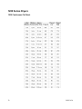
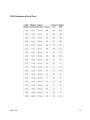
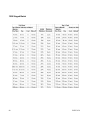
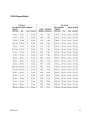
Drying Charts................................................................77
1200 Series.......................................................................................................78
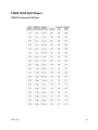
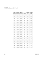
1200S Series....................................................................................................81
Section 10
Technical Reference.....................................................85
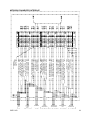
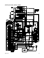
Control Panel Jumper Wiring..............................................................................86
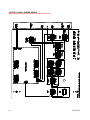
Control Panel Internal Wiring...............................................................................87
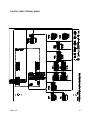
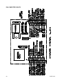
Lower Control Box Back Panel Wiring..................................................................88
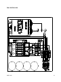
Network Fan/Heater Interface..............................................................................89
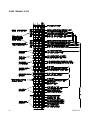
Fan Computer Pinouts.......................................................................................90
Fan Can Control Box..........................................................................................91
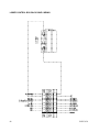
Upper Terminal Strip...........................................................................................92
Upper Control Back Panel Wiring........................................................................93
4
PNEG-950
Introduction
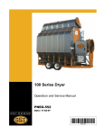
GSI Network Portable Dryers
Thank you for choosing a GSI product. It is designed to give excellent performance and service for many years.
This manual describes the operation and service for all standard 1200 series two fan grain dryers. These models are available for liquid propane,
natural gas, or fuel oil fuel supply, with either single phase 230 volt, three
phase 220, 380, 440, or 575 volt electrical power.
The principal concern of GSI Group, Inc. (“GSI”) is your safety and the safety
of others associated with grain handling equipment. This manual is written
to help you understand safe operating procedures, and some of the problems that may be encountered by operator or other personel.
As owner and/or operator, it is your responsibility to know what requirements, hazards and precautions exist, ant to inform all personnel associated with the equipment, or who are in the dryer area. Avoid any alterations
to the equipment. Such alterations may produce a very dangerous situation, where serious injury or death may occur.
This dryer is designed solely for the purpose of drying
agricultural corn, grain, and seeds. Use of this dryer in
any ways or under configurations other than those
indicated in this manual is a misuse of the machine, will
invalidate the warranty, and may lead to serious injury or
death. If in any doubt, contact GSI or your dealer.
PNEG-950
5
2 Fan Network Dryer Manual
GSI Group, Inc.
All rights reserved. No parts of this work may be reproduced in any form or by any means - graphic, electronic,
or mechanical, including photocopying, recording, taping, or information storage and retrieval systems - without the written permission of the publisher.
Products that are referred to in this document may be either trademarks and/or registered trademarks of the
respective owners. The publisher and the auther make no claim to these trademarks.
While every precaution has been taken in the preparation of this document, the publisher and the author
assume no responsibility for errors or omissions, or for damages resulting from the use of information contained in this document or from the use of programs and source code that may accompany it. In no event shall
the publisher and the author be liable for any loss of profit or any other commercial damage caused or alleged
to have been caused directly or indirectly by this document.
Printed: May 2002 in (Assumption, Illinois)
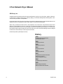
History
1988
Portable Dryer line introduced
15 models produced
1989
71 dryers produced
1990
102 dryers produced
1991
94 dryers produced
1992
116 dryers produced
1993
Computerized controls introduced
220 dryers produced
34 were old style controls
1995
Competitor dryer introduced
1999
Network dryer introduced
EMCS controller discontinued
6
PNEG-950
Section
1
Warranty
THE GSI GROUP, INC. WARRANTY
THE GSI GROUP, INC. (“GSI”) WARRANTS ALL PRODUCTS WHICH IT MANUFACTURES TO BE
FREE OF DEFECTS IN MATERIAL AND WORKMANSHIP UNDER NORMAL USAGE AND
CONDITIONS FOR A PERIOD OF 12 MONTHS AFTER RETAIL SALE TO THE ORIGINAL END
USER. THE PURCHASER’S SOLE REMEDY AND GSI’S ONLY OBLIGATION SHALL BE TO
REPAIR OR REPLACE, AT GSI’S OPTION AND EXPENSE, PRODUCTS THAT, IN GSI’S SOLE
JUDGMENT, CONTAIN A MATERIAL DEFECT DUE TO MATERIALS OR WORKMANSHIP. ALL
DELIVERY AND SHIPMENT CHARGES TO AND FROM GSI’S FACTORY WILL BE
PURCHASER’S RESPONSIBILITY. EXPENSES INCURRED BY OR ON BEHALF OF THE
PURCHASER WITHOUT PRIOR WRITTEN AUTHORIZATION FROM AN AUTHORIZED
EMPLOYEE OF GSI SHALL BE THE SOLE RESPONSIBILITY OF THE PURCHASER.
EXCEPT FOR THE LIMITED WARRANTY EXPRESSED ABOVE, GSI MAKES NO FURTHER
WARRANTY OF ANY KIND, EXPRESS OR IMPLIED, INCLUDING, WITHOUT LIMITATION,
WARRANTIES OF MERCHANTABILITY OR FITNESS FOR A PARTICULAR PURPOSE OR USE IN
CONNECTION WITH (I) PRODUCT MANUFACTURED OR SOLD BY GSI OR (II) ANY ADVICE,
INSTRUCTION, RECOMMENDATION OR SUGGESTION PROVIDED BY AN AGENT,
REPRESENTATIVE OR EMPLOYEE OF GSI REGARDING OR RELATED TO THE CONFIGURATION,
INSTALLATION, LAYOUT, SUITABILITY FOR A PARTICULAR PURPOSE, OR DESIGN OF SUCH
PRODUCTS.
GSI SHALL NOT BE LIABLE FOR ANY DIRECT, INDIRECT, INCIDENTAL OR
CONSEQUENTIAL DAMAGES, INCLUDING, WITHOUT LIMITATION, LOSS OF ANTICIPATED PROFITS
OR BENEFITS. PURCHASER’S SOLE AND EXCLUSIVE REMEDY IS AS SET FORTH IN THE LIMITED
WARRANTY EXPRESSED ABOVE, WHICH SHALL NOT EXCEED THE AMOUNT PAID FOR THE
PRODUCT PURCHASED. THIS WARRANTY IS NOT TRANSFERABLE AND APPLIES ONLY TO THE
ORIGINAL PURCHASER. GSI SHALL HAVE NO OBLIGATION OR RESPONSIBILITY FOR ANY
REPRESENTATIONS OR WARRANTIES MADE BY OR ON BEHALF OF ANY DEALER, AGENT OR
DISTRIBUTOR OF GSI.
GSI ASSUMES NO RESPONSIBILITY FOR CLAIMS RESULTING FROM ERECTION
DEFECTS OR UNAUTHORIZED MODIFICATIONS TO PRODUCTS WHICH IT MANUFACTURED.
MODIFICATIONS TO PRODUCTS NOT SPECIFICALLY DELINEATED IN THE MANUAL
ACCOMPANYING THE EQUIPMENT AT INITIAL SALE WILL NULLIFY THE PRODUCT WARRANTY
THAT MIGHT HAVE BEEN OTHERWISE AVAILABLE.
THE FOREGOING WARRANTY SHALL NOT EXTEND TO PRODUCTS OR PARTS
WHICH HAVE BEEN DAMAGED BY NEGLIGENT USE, MISUSE, ALTERATION OR ACCIDENT. THIS
WARRANTY EXTENDS SOLELY TO ONLY PRODUCTS MANUFACTURED BY GSI. THIS WARRANTY
IS EXCLUSIVE AND IN LIEU OF ALL OTHER WARRANTIES EXPRESS OR IMPLIED. GSI RESERVES
THE RIGHT TO MAKE DESIGN OR SPECIFICATION CHANGES AT ANY TIME.
PRIOR TO INSTALLATION, PURCHASER HAS THE RESPONSIBILITY TO COMPLY
WITH ALL FEDERAL, STATE AND LOCAL CODES WHICH MAY APPLY TO THE LOCATION AND
INSTALLATION OF PRODUCTS MANUFACTURED OR SOLD BY GSI.
PHLEGAL: #1832020 v1 (139LG01!.DOC)
(revised December 2005)
Section
2
Safety First
DRYER OPERATION
Thank you for choosing a GSI product. It is designed to give excellent performance and service for many
years.
This manual describes the operation and service for all standard 100 Series single fan grain dryers.
These models are available for liquid propane or natural gas fuel supply, with either single phase 230 volt, or
three phase 220 or 440 volt electrical power.
The principal concern of the GSI Group, Inc. ("GSI") is your safety and the safety of others associated with grain
handling equipment. This manual is written to help you understand safe operating procedures, and some of the
problems that may be encountered by the operator or other personnel.
As owner and/or operator, it is your responsibility to know what requirements, hazards and precautions exist,
and to inform all personnel associated with the equipment, or who are in the dryer area. Avoid any alterations to
the equipment. Such alterations may produce a very dangerous situation, where serious injury or death may
occur.
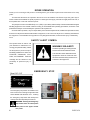
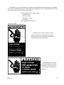
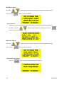
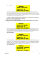
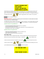
SAFETY ALERT SYMBOL
The symbol shown is used to call
your attention to instructions con-
WARNING! BE ALERT!
cerning your personal safety. Watch
Personnel operating or working around
for this symbol; it points out impor-
electric fans should read this manual.
tant safety precautions. It means "AT-
This manual must be delivered with the
TENTION", "WARNING", "CAU-
equipment to its owner. Failure to read
TION", and "DANGER". Read the
this manual and its safety instructions is
message and be cautious to the
a misuse of the equipment.
possibility of personal injury or
death.
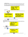
EMERGENCY STOP
Decal: DC-1317
The emergency stop switch is located on the
lower control box on the upper right hand side
and is labeled with decal DC-1317. Pushing
the emergency stop switch will interrupt the
control power and stop all dryer functions.
WARNING: Pushing the emergency
stop switch does not interrupt the
main power to the upper control
box panel.
10
PNEG-950
The GSI Group, Inc. recommends contacting your local power company, and having a representative survey your installation
so the wiring is compatible with their system, and adequate power is supplied to your unit. Safety decals should be read
and understood by all people in the grain handling area.
If a decal is damaged or is missing contact:
The GSI Group, Inc.
1004 E. Illinois St.
Assumption, IL 62510
217-226-4421
A free replacement will be sent to you.
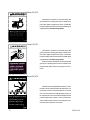
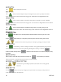
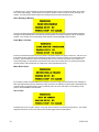
Decal: DC-1224
Decal DC-1224 is located in two places on the fan/
heater control box. One on the lid and one on the front of
the fan heater control box. Another location for this decal
is inside the upper control box for the dryer.
Decal DC-889 has two locations.
One inside the fan/heater control box
and another on the dryer upper control box door next to the main power
disconnect.
Decal: DC-889
PNEG-950
11
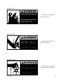
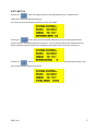
Decal: DC-972
Decal DC-972 is located on the bottom auger belt
guard and the front bearing plate (which is visible when
then bottom auger belt guard is removed). An alternate
location would be at the rear of the dryer for portable dryers
equipped with the Front Discharge Option.
Decal: DC-971
Decal DC-971 is located on the bottom auger belt
guard and the front bearing plate (which is visible when
then bottom auger belt guard is removed). An alternate
location would be at the rear of the dryer for portable dryers
equipped with the Front Discharge Option.
Another location for decal DC-971 is the top auger belt
guard (one on the belt guard cover and one inside on the
belt guard body visible when the belt guard cover is remove).
Decal: DC-974
Decal DC-974 has several different locations. Two are
located on the front end panel below the fan/heater. Two
are located on the rear end panel below the rear access
door. Two are located on the auger discharge box (one on
the outside top and one on the inside of the flapper lid next
to the discharge mercury switch). One more of these decals is located inside the plenum on the rear plenum closure door just inside the rear access door.
12
PNEG-950
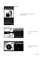
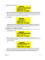
Decal: DC-1227
Decal DC-1227 is located on the
fan/heater access door.
Decal: DC-1225
Decal DC-1225 is located on the
fan/heater access door.
Decal: DC-1229
Decal DC-1229 is located on
each of the meter roll access doors.
PNEG-950
13
Decal: DC-973
Decal DC-973 is located on the rear plenum access
door (inside and outside).
Decal: DC-388
Decal DC-388 is located on the
hitch tongue.
Decal: DC-1249
Decal DC-1249 is located on the
hitch tongue.
14
PNEG-950
READ THESE INSTRUCTIONS
BEFORE OPERATION AND SERVICE
SAVE FOR FUTURE REFERENCE
1.
Read and understand the operating manual before trying to operate the dryer. This manual contains important guidelines
and sequence of events to help you install and operate your dryer safely and successfully. Follow the guide lines closely.
2. After towing the dryer, ensure it is parked on a level surface and that suitable precautions have been taken to prevent it
from rolling, i.e. block the wheels in both directions.
3.
Never operate the dryer while the guards are removed.
4. BEFORE any maintenance switch the dryer OFF at the mains electricity and lock off. This should include all associated
conveyers, augers and other associated equipment. Maintenance requiring the power to be ON, such as testing electrical
circuits, must be done by qualified personnel.
5. Check for gas leaks at all gas pipe connections. If any leaks are detected, do not operate dryer. Shut down and repair
before further operation.
6.
Never attempt to operate the dryer by jumping or otherwise bypassing any safety devices on the unit.
7. Set pressure regulator to avoid excessive gas pressure applied to burner during ignition and when burner is in operation.
Do not exceed maximum ended drying temperature.
8.
Keep the dryer clean. Do not allow fine material to accumulate in the plenum chamber.
9.
Keep auger drive belts tight enough to prevent slippage.
10. Never work in or on the dryer while it is on or when the electrical supply is on as the fans, augers and burners may start
automatically.
11. Keep the air inlet to the fan clear of any obstructions and free from combustible materials.
12. Before attempting to remove and re install any blade, make certain to read the recommended procedure listed within the
servicing section of the manual.
13. Be certain that capacities of auxiliary conveyers are matched to dryer auger capacities.
14. Clean grain is easier to dry. Fine material increases resistance to airflow and requires removal of extra moisture.
15. Never enter the dryer plenum chamber unless:
a) The electrical power is locked off and the key is in your possession.
b) The gas is shut off from the gas supply.
c) The dryer has stopped operating and is cool.
16. Dust and noise are inherent hazards with this type of machine, which can be harmful to your health. To reduce risks:
a) Avoid working around the dryer.
b) When around the dryer, wear suitable ear defenders and a dust mask suited to protection against grain dust.
USE CAUTION IN THE OPERATION OF THIS EQUIPMENT
The design and manufacture of this dryer is directed toward operator safety. However, the very nature of a
grain dryer having a gas burner, high voltage electrical equipment and high speed rotating parts, does present a hazard
to personnel which can not be completely safeguarded against, without interfering with efficient operation and reasonable access to components.
Use extreme caution in working around high speed fans, gas fired heaters, augers and auxiliary conveyers,
which may start without warning when the dryer is operating on automatic control.
Continued safe, dependable operation of automatic equipment depends, to a great degree, upon the owner.
For a safe and dependable drying system, follow the recommendations within this manual, and make it a practice to
regularly inspect the operation of the unit for any developing problems or unsafe conditions.
Take special note of the safety precautions listed above before attempting to operate the dryer.
PNEG-950
15
16
PNEG-950
Section
3
Control Panel
18
PNEG-950
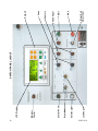
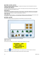
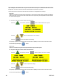
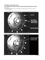
Load Auger
Outside Light
Dryer Mode
Control Power
Moisture
Control
LCD Display
SWITCH PANEL LAYOUT
Meter Roll
Adjustment
Stop
Start
Unload Auger
Heaters
Fans
Keypad
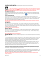
CONTROL POWER SWITCH
The control power to energize the Network Control System is turned on or off with this switch.
Note: This switch does not disconnect the power that is present at the breakers, contactors,
transformer(s), fuses or other electrical components found in the upper and lower control boxes. Turn the
Main Disconnect Handle to the OFF posistion prior to servicing any of the installed components.
DRYING MODE SWITCH
This is used to select staged batch or continuous flow drying. The switch will light only after the Network Control
System has been turned on, the safety circuit is okay and the
pressed.
button on the control panel has been
LOAD AUGER SWITCH
This is used to select the operation of the fill auger. In both the auto and manual position the load auger will
operate if the dryer is low on grain and will automatically shut off when the dryer is full. In the auto position only, the
dryer will shut down after a preset period of time set on the out of grain timer, or if grain flow is interrupted to the
dryer. The switch will light whenever the load auger is operating.
Note: If the load auxiliary controls are being used, this switch will also control the operation of the auxiliary equipment.
FAN SWITCH
Each fan is turned on or off with this switch. The on position operates the fan continuously during staged batch
and continuous flow modes. The auto position operates the fan in staged batch during the dry and cool cycle but
the fan will not operate during the unload cycle. The switch will light up whenever the air pressure switch is sensing
air pressure and the dryer is full of grain.
Note: The bottom fan on your dryer is always Fan 1.
HEATER SWITCH
Each burner is turned on or off with this switch. The auto position operates the burner in staged batch during the
dry cycle only. The on position will operate the burner only when the fan is running. The switch will light up only
when the flame sensor detects the flame.
Note: The bottom burner on your dryer is always Burner 1.
UNLOAD SWITCH
The unload switch turns the metering rolls and discharge auger on or off, and selects the operation of the metering
rolls.
• In the 2 speed position if the moisture control switch is on, and the drying mode switch is turned to cont. flow, the
metering roll speed will alternate between the high speed metering roll potentiometer setting and the low speed
metering roll potentiometer setting depending on whether the grain temperature is above or below the grain
temperature setpoint. The discharge auger will operate continuously.
• In the 1 speed position, if the moisture control switch is on, and the drying mode switch is turned to cont. flow,
the metering roll speed will discharge grain at the high speed metering roll potentiometer setting or turn off the
meter rolls depending on whether the grain temperature is above or below the grain temperature setpoint. The
discharge auger will operate whenever the metering rolls are operating.
• In both the 1 speed or the 2 speed position, if the moisture control switch is off, and the drying mode switch is
turned to cont. flow, the metering roll speed can be manually controlled by adjusting the high speed metering roll
potentiometer. The discharge auger will operate continuously.
• If the drying mode switch is turned to staged batch, the unload switch should be set to the 1 speed position. The
discharge auger and metering rolls will only operate during the unload cycle of the staged batch operation, and the
speed of the metering rolls is adjusted using the high speed metering roll potentiometer.
Note: If the unload auxiliary controls are being used, this switch will also control the operation of the
auxiliary equipment.
PNEG-950
19
MOISTURE CONTROL SWITCH
This switch activates the moisture control circuit. It lights up when the grain column temperature is below the
moisture control (grain temperature) set point.
OUTSIDE LIGHT SWITCH
The dryers outside service light is turned on or off here. It also may be set on auto, which turns the light on while
the dryer is running and off if a shutdown occurs.
RUN SWITCH
This switch starts and operates the dryer based on switch settings. If other switch settings are in the off position,
individual dryer components can be operated by turning the drying mode switch to continuous flow, pressing the
dryer power run button and then turning on the desired dryer component.
STOP SWITCH
This switch stops all dryer functions. If an automatic dryer shutdown occurs, first determine and correct the cause
of the shutdown. Then, press the dryer power stop button to reset the dryer before restarting.
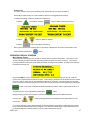
KEYPAD LAYOUT
All of the timer settings, delays and operational dryer parameters are setup with the keypad.
Listed below is a description of the buttons used on the keypad.
RESET BUTTON
On this screen is information on the version of software that is installed on your dryer.
Press
the
button to intialize the dryer. The computer will run a series of tests on its internal
components. The dryer controls will not operate until this button has been pressed.
20
PNEG-950
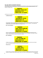
SETUP BUTTON
Pressing the
button while the system is stopped, will give you four setup screens. These are:
This screen is used to clear your batch counter. You may want to do this at the start of the drying season
to keep an accurate count of the batches ran through your dryer during the drying season. Press the
button to clear it or just press the
button to keep your total batch count.
The next screen allows you to clear the total amount of bushels that your dryer has recorded. Press the
button to clear it or just press the
button to keep your total bushels count.
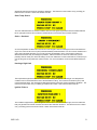
This screen is used to customize your dryer with the name of your farm or company. This message will contain the
serial number of the dryer when it leaves the factory but can be changed to anything message
you like. Use the
cursor, press the
to change the character above the flashing cursor. To move the
button to advance to the next character or the
button to back up to the
previous character on the line. When you have finished entering your custom message press
the changes.
Press the
PNEG-950
to accept
button to accept the new setting.
21
DELAY BUTTON
The
button will display four different setup screens.
The screens will display in the following order:
Load On Delay - amount of time before fill auger starts once fill switch has been activated see
Out of Grain Timer - amount of time fill auger will run until fill switch has been activated
Fan Sequencing Delay - minimum amount of time between each fan startup
Unload Cleanout Delay - amount of time unload continues to run once meter rolls have stopped
SCREENS BUTTON
Press the
button and the display will then show a menu selection screen.
This allows you to select between 3 different choices.
• Out of Grain Time - allows you to view or change the Out of Grain Timer, or view how long it took for your
dryer to fill.
• View Grain Temps - allows you to view your grain temperatures on different modules (if so equipped).
• Meter Roll SP Avg - shows you the percentage of time that the speed of the meter rolls system has spent
on HI or Low speed.
Press the
buttons to move the pointer and allow you to select any of the three choices and
then press the
button to jump to the next menu selection.
Out of Grain Time
Press the
button and move the pointer to change your selection or just press the
button on the Out of Grain Time selection gives you an additional 3 choices relating to your Out of Grain Timer.
• Set Out of Grain - will allow you to change your Out of Grain Timer settings
• Out of Grain Tmr - view the Out of Grain timer
• Last Load Time - displays the amount of time it took for the fill paddle switch to become activated or the
dryer filled.
Pressing the
button again on the Set Out of Grain allows you to adjust the time it takes for your dryer
to run whenthe load paddle switch has not been activated. If this timer expires, your dryer will shut down giving you
a out of grain warning. If you have a slow fill auger system, you would probably want to set this setting to a high
value.
22
PNEG-950
Set Out of Grain
The Out of Grain timer should be set to the maximum time it takes for your dryer to refill during continious or
batch mode drying.
If the dryer runs out of grain while the load auger switch is in the auto position, the out of grain timer automatically shuts off the dryer after the period of time preset on the timer.
Press the
button to edit the timer settings. Press the
button to adjust the
timer value.
Press the
button to accept the changes.
Out of Grain Timer
From this screen, you can view the amount of time left on your Out of Grain timer and view the amount of
time it took to load your dryer the time before.
See Out of Grain Timer for more information.
Last Load Timer
This screen shows you how much time the load or fill auger operated until being deactivated by the fill auger
mercury switch. This information can be useful for determining the amount of time you need to place into
your setting.
See Out of Grain Timer for more information.
PNEG-950
23
View Grain Temps
Press the
Then press the
button and move the pointer to change your selection to View Grain Temps.
button to accept the selection.
Grain Temperatures
This allows you to look at detailed temperature information on each fan and heater that is installed on
your dryer. Press the
button to toggle between the fan/heaters or press the
to exit out of this screen.
Meter Roll SP Avg
Press the
Then press the
button and move the pointer to change your selection to Meter Roll SP Avg.
button to accept the selection.
Meter Roll Speed Ave Selection
Press the
24
button to accept the View MR Speed Ave selection.
PNEG-950
View MR Speed Average
On this screen is information showing you how much time the metering roll system has spent on HI speed
and LOW speed. The ideal values of course is at 50% each, although in real world situations this is very
difficult to obtain. Having a 30% - 70% reading is not uncommon but anything over this may indicate that
meter roll speed settings may need adjusting. This can vary throughout the day due to a number of conditions including drying wetter grain or ambient temperature changes of 108 or more.
Reset MR Average
Press the
button and move the pointer to change your selection to Reset MR Average
and press the
button.
You can reset the speed average by pressing the
pressing the
button or you can exit out of this function by
button and goto the User Hour Meter screens.
User Hour Meter
The User Hour Meter is a custom timer which can be used for several different scenarios. For instance, if you
wanted to monitor the amount of time used between different hybrids of corn or if you have more then one user of
the dryer.
Press the
button to exit back to the main drying screen.
Reset User Hour Meter
Pressing the
button at this point will cause the to be reset back to 0.
If this is not the desire action then press the
PNEG-950
button to exit back to the main drying screen.
25
HELP BUTTON
The
button currently has no function.
DRY BUTTON
The
button is used to change the Dry timer settings when you operate your dryer in the Batch
mode. This button has no effect in the continous drying mode. Please refer to the Staged Batch section.
COOL BUTTON
The
button is used to change the Cool timer settings when you operate your dryer in the Batch
mode. This button has no effect in the continous drying mode. Please refer to the Staged Batch section for Batch
operation.
UNLOAD BUTTON
The
button is used to change the Unload timer settings when you operate your dryer in the
Batch mode. This button has no effect in the continous drying mode. Please refer to the Staged Batch section for
Batch operation.
PLENUM BUTTON
The
ing the
button allows you to view the plenum temperature of all the burners on your dryer. Press
button allows you to change the plenum set point of the burner being viewed. Press
to advance to the next screen (burner) or to accept any changes you may have made.
GRAIN BUTTON
The
button allows you to view or modify the moisture control (grain temperature) set point which
determines the final moisture content of the grain being discharged from the dryer. Press the
button to make any changes. Press
to advance to the next screen or to accept any changes you may
have made.
MODIFY BUTTON
When viewing a screen with settings that can be changed, the
button will allow you to edit the
values on this screen. Otherwise this button will have no function available.
INCREASE and DECREASE BUTTONS
The
are used when you are editing temperature, time values or for scrolling up and
down the different screen selections.
ENTER BUTTON
Use the
button to accept any changes you may have made to timer, delay or setup screens. It
is also used to advance to the next screen.
26
PNEG-950
STATS BUTTON
Pressing the
button will toggle the last line of the main display screen to 3 different views
relating to the dryers approximated output rate.
This screen shows the actual turning speed of the meter rolls in RPM.
Pressing the
button again shows an approximated Bushel per hour that have passed through
the dryer using the above RPM readings as a reference. This can vary depending on the cleanliness and test
weight of the grain and/or the position of the slide gates located directly above the turning metering rolls.
Pressing the
button again shows an approximated Total Bushels that have passed through the dryer
using the above RPM readings as a reference.
PNEG-950
27
28
PNEG-950
Section
4
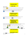
Dryer Pre Season Checks
This section gives a series of checks to be carried out on the dryer before starting for the first time in the
drying season. If any of the checks fail to produce the stated result, you should consult your dealer.
YOU SHOULD NOT ATTEMPT TO USE THE DRYER UNLESS ALL THE PRE-START CHECKS
HAVE BEEN SUCCESSFULLY COMPLETED.
BEFORE ATTEMPTING TO OPERATE THE DRYER MAKE SURE ALL
SAFETY SHIELDS ARE IN PLACE, ALL BOTTOM CLEANOUT AND
REAR ACCESS DOORS ARE CLOSED AND ALL PERSONNEL ARE
CLEAR OF THE DRYER
INSPECT THE METERING ROLLS
Open all metering roll access doors and inspect each compartment for any bolts, nuts or other foreign material,
that may cause possible jamming of the metering rolls.
ELECTRICAL POWER
Turn on the electrical power supply to the dryer, set all circuit breakers to on, including the safety disconnect
handle mounted on front of the dryer power panel.
CONTROL POWER SWITCH
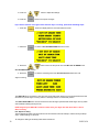
Turn the control power switch to on. The switch will light up. A copyright message, model number, total running
time in hours and minutes, current date and time will appear. At this point the controller will lock out all other dryer
functions. Once the date and time appear, press the
button and the dryer will perform a safety circuit
check. If a fault is found, the cause will be displayed on the LCD. If all are found safe, the controller will supply
power to the electronic fuel shut-off valve (Maxon), if so equipped, and the drying mode switch will light up, indicating that the dryer is ready to be started.
RUN BUTTON
Push the dryer run button, and all the selector switches on the control panel will be activated.
FUEL CHECK
If using LP gas, make sure the tank has plenty of fuel and that the tank must not have a regulator mounted on the
liquid line. Slowly open the main fuel supply valve at the tank. Then, open the electronic shut off valve (Maxon
valve), if so equipped, or open the manual shut off valve on the dryer to allow fuel flow to the dryer.
If using natural gas, make sure an adequate supply is available. Turn on the valve along the supply line. Then,
open the electronic shut off valve (Maxon valve). Inspect all gas lines and connections for possible leaks.
Any gas leaks must be fixed immediately!
30
PNEG-950
LOAD AUGER
With the grain supply shut off, quickly bump the load auger switch to manual, and see if the load auger rotates
clockwise as viewed from the drive end, or counterclockwise if the dryer is a front load model. If the wet grain
supply auxiliary is wired to the dryer it should also rotate in the correct direction at this time.
Turn the load auger switch to the auto position. The top auger and wet grain supply auxiliary should run for eight
(8) minutes, and then the dryer will shutdown leaving the safety shutdown message (out of grain warning) displayed. Press the dryer power stop button to reset the panel, then press the start button.
UNLOAD ONE SPEED OPERATION
To check one speed operation place the unload switch in the one speed setting. Turn the metering roll dial until
the metering rolls start rotating. The bottom auger should rotate counterclockwise as viewed from the drive end.
The metering roll drive motor should rotate clockwise as viewed from the drive end of the gear box. If the dry grain
take away auxiliary is wired to the dryer, it should start and rotate in the proper direction.
UNLOAD TWO SPEED OPERATION
To check two speed operation move the unload switch to the two speed position, change the low speed reading to
200 and high speed on 600. Adjust the moisture control (grain temperature) setpoint to a value lower then the
ambient temperature or until the moisture control switch light comes on. The metering roll speed is now controlled
by the low speed setting. Adjust the moisture control (grain temperature) setpoint to a value higher then the
ambient temperature or until the light goes out leaves the metering rolls controlled by the high speed setting.
METERING ROLL OPERATION
To check the metering roll operation turn the knob clockwise, and the metering roll speed should increase. Turning
either knob counterclockwise will decrease the speed. Make sure the drive chain tension is properly adjusted and
all sections of the metering rolls rotate. Turn the unload switch off after these checks are complete. The bottom
auger will continue to run for 60 seconds (default cleanout delay setting) after the switch is turned off to allow for
cleanout.
Note: Due to the nature of the DC drive motor used on the meter rolls, it is possible for the brushes inside
the motor to become corroded if the dryer has not been operated for several months. This will cause the
meter rolls not to function. To fix this problem, use a rubber mallet or a piece of wood to tap the DC drive
motor. The shock is usually all the motor needs to start working again. You should not have any more
problems with this during the rest of your drying season.
Meter Roll 1 Speed Display
This is used to adjust the speed of the metering roll when the single speed automatic moisture control feature
of the dryer is in use.
This is used to:
• Set the speed of the metering rolls when the one speed automatic moisture control feature of the dryer is
utilized.
• Set the speed of the metering rolls during continuous flow operation or .
Just turn the meter roll adjustment knob and put the is in the single speed position, your display will now show
the following:
If you are finished with your adjustments, press the
button. The screen will also return to the main
display if you don’t turn or press the knob for about 8 seconds.
PNEG-950
31
Meter Roll 2 Speed Display
• Set the speed of the metering roll when the two speed automatic moisture control feature of the
dryer is utilized.
If you turn the meter roll adjustment knob and the unload switch is in the two speed position, you can adjust
your 2 speed settings. Notice that the numbers next to Low is flashing. This indicates that any adjustment you
make with the meter roll know will only affect this setting. To change the High setting, press the meter roll
adjusment knob until it clicks. You screen should now flash the numbers next to the High setting. Any adjustment made at this point will only affect this setting.
If you are finished with your adjustments, press the
button. The screen will also return to the main
display if you don’t turn or press the knob for about 8 seconds.
Note: This screen is only available if the moisture control switch is on and the unload switch is in the 2
speed position.
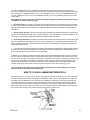
FAN SWITCHES
Momentarily turn each fan switch to on and observe the fan rotation. The fan should run counterclockwise. Sometimes on three phase models all motors will run backwards. They can easily be reversed by interchanging two of
the three power supply wires. All power should be switched and locked off before attempting to reverse the
connections. Reverse the two outside wires, L1 and L3, and leave the middle one in the same position.
Note: The bottom fan on your dryer is always refered to as Fan 1.
BURNER SAFETY
To check the burner safety function, first make sure the main gas valve is off. Turn the fan switch on and allow the
fan to start. Then, turn the heater switch on for that fan. The dryer will shut down after 20 seconds. The safety
message, “Ignition Failure x” will appear. Reset the dryer and repeat for the other fan/heater(s).
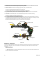
BURNER TEST FIRE
Test fire each burner by starting the fan. Then, turn the burner switch to on. Turn on the fuel supply, and the
burner should ignite after a short purge delay of approximately 10 seconds. Gas pressure should be shown on the
gauge. At this time adjust the plenum set point to 200°F (93°C), causing the burner to operate on hi-fire. Observe
the gas pressure on gauge, and lower the plenum set point until it causes the burner to cycle into lo-fire. When the
plenum temperature set point is met, the gas pressure should show a noticeable drop, indicating that the cycling
solenoid is closed and the burner is being supplied with less gas through the bypass valve. At this time set the hifire and lo-fire pressure settings. Use the pressure regulator for hi-fire and the cycling solenoid needle valve for lofire. The computer should cycle the burners between high and low, approximately 4 to 5 times per minute.
Only use pressure required to obtain desired temperature.
Approximate settings should be:
LP Gas
Natural Gas
Hi-Fire 6-15 PSI (41-102 kPa)
Lo-Fire 2-6 PSI (14-41 kPa)
Hi-Fire 6-10 PSI (41-69 kPa)
Lo-Fire 1-3 PSI (7-20 kPa)
If the burner remains on hi-fire and does not cycle, increase the regulator setting on the propane models,
or the supply valve on the natural gas models in order to reach the plenum set point. If the burner remains in lofire and does not cycle, slightly decease gas pressure with the cycling solenoid needle valve. If the gas pressure is
32
PNEG-950
decreased too much a popping or fluttering sound will be heard. Also, anytime the high pressure side is adjusted,
the low pressure side needs to be checked. Repeat the test for each fan/heater unit.
DRYER SHUTDOWN
To shut down the dryer,
1. Close the fuel supply valve at the tank or valve along the fuel line.
2. If the burner is operating, let the dryer run out of fuel, and it will shut down automatically due to loss of flame.
3. Close the fuel valve at the dryer, and press the dryer power stop button.
4. Turn off the control power.
5. Turn off the safety disconnect handle on the front of the power box, and turn off the main power to the dryer.
EMERGENCY DRYER SHUTDOWN
In case of emergency push the dryer stop button or the emergency stop button. This will interupt power to the
control panel and the fan, burner and all augers will stop immediately.
PNEG-950
33
34
PNEG-950
Section
5
Dryer Startup and Operation
FULL HEAT DRYING
Full Heat Operation
With this type of drying, the grain is discharged hot, with no cooling. Drying capacity is substantially higher with
FULL HEAT than the DRY AND COOL process.
Dryeration Process
The full heat process is called “DRYERATION”. Recommended procedure is to temper the hot grain for 4 to 10
hours in a cooling bin or storage bin, then cool by an aeration fan at an air flow rate of 1/2 to 1 CFM per bushel of
grain in the hot batch being cooled. The process of tempering and slow cooling provides higher quality in shelled
corn because of less stress cracking of kernels and less breakage during subsequent handling of the grain.
Final Moisture
From 1 to 3% apparant moisture is usually removed in the cooling process, so hot shelled corn is removed from
the dryer at about 17% moisture if the final desired moisture content is 15%.
DRYING TEMPERATURES
Shelled Corn
For shelled corn with an initial moisture content of 25-30%, the recommended maximum drying temperature is
220-240° F (104-116° C) for the top fan and 170-190° F (7788° C) for the bottom fan. For lower initial moisture
content, lower drying temperatures are recommended.
Small Grain
For drying small grain (wheat, oats, milo), 150° F (66° C) is suggested.
Rice, Soybeans
Drying temperatures are critical in drying rice and soybeans. A temperature of 130° F (54° C) is recommended to
keep grain temperature low.
Drying Efficiency
The general rule for obtaining the highest drying efficiency is to use the highest possible drying temperatures which
will not adversely affect grain quality.
Dryer Shutdown
Cooling Hot Grain
If the dryer is to be shut down while filled with grain, it is recommended that hot grain be cooled for 10 to 15
minutes, especially in cold weather, to prevent water vapor condensation and possible freezing of such condensate
following shut down.
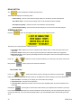
INITIAL SETUP PARAMETERS
Timer and Delay Settings
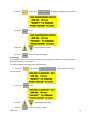
Turn the control power switch to on. The monitor will display a copyright message and model number, total
running time in hours and minutes and the current time and date. To activate the controller press
the
button.
Fan and Auger Delays
The
button will display four different setup screens. Press the
each setup screen or the
button to bypass
button to edit the delay currently on display.
The screens will display in the following order:
Load On Delay
Out of Grain Timer
Fan Sequencing Delay
Unload Cleanout Delay
36
PNEG-950
Load Delay
The load delay is used to delay the starting of the load auger when the dryer is unloading to prevent the load
auger from cycling to often. To change the setting of this delay follow these instructions:
1.
Press the
button.
2.
Press the
button.
3.
Press the
4.
Press the
button to adjust the settings.
button to accept the changes.
Out of Grain Timer
The Out of Grain timer should be set to the maximum time it takes for your dryer to refill during continious or
batch mode drying.
If the dryer runs out of grain while the load auger switch is in the auto position, the out of grain timer automatically shuts off the dryer after the period of time preset on the timer.
1.
Press the
button. Press
2.
Press the
button.
PNEG-950
to bypass the first screen.
37
3. Press the
4. Press the
button to adjust the settings.
button to accept the changes.
If you want to view the out of grain timer while the dryer is running, perform the following steps:
1. Press the
button the display will then show this selection screen:
2. Press the
to view the OUT OF GRAIN TIME selection screen.
3. Press the
button and move the pointer from the SET OUT OF GRAIN to the
OUT OF GRAIN TMR position.
4. Press the
to view the remaining time of the Out of Grain timer while the Load
Auger is running.
The TIME LEFT is a countdown of time from the Out of Grain timer setting you have entered above and will
decrement if your fill auger is running and the Load Auger switch is in the AUTO position.
The LAST LOAD TIME is the amount of time the load or fill auger operated until the fill auger mercury switch
was activated indicating the dryer is full.
NOTE: Anytime your TIME LEFT counter reaches zero, your dryer will shut down with a “Out of
Grain” warning.
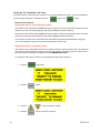
Fan Sequence Delay
The Fan Sequence Delay controls the amount of time between each fan startup to reduce the dryer startup
amps. Default setting is 5 seconds.
To change the setting of this delay follow these instructions:
38
PNEG-950
1. Press the
button. Press
2. Press the
button.
3. Press the
4. Press the
(enter twice) to bypass the other screens.
button to adjust the settings.
button to accept the changes.
Unload Delay
The unload delay is used to control the amount of time the unload auger runs after the metering rolls stop to
allow the unload auger to clean itself out.
To change the setting of this delay follow these instructions:
1.
Press the
button. Press
(enter three times) to bypass
the other screens.
2.
Press the
3.
Press the
4. Press the
PNEG-950
button.
button to adjust the settings.
button to accept the changes.
39
Setting Up The Temperature Set Points
These set points are monitored by the computer to control certain features of the dryer. These can be adjusted
from the keypad of the Dryer control panel using the
button or the
button.
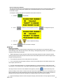
Moisture Control Setpoint
Drying mode switch is in the Continuous position:
If the moisture control temperature is below this set point and you have your unload switch set to two speed
position then meter rolls will discharge the grain using the low speed meter roll setting.
If the moisture control temperature is above this set point and you have your unload switch set to two speed
position then meter rolls will discharge the grain using the high speed meter roll setting.
It is normal for the meter rolls to switch back and forth between high and low speed during the drying process. This regulates the speed of the grain being discharged from the dryer.
Drying mode switch is in the Batch position:
If the moisture control temperature is below this set point and the Dry Timer has reached zero, the heater will
continue to fire until the moisture control set point has been reached. During this cycle the moisture control
light will flash and a message on the display will read TEMPERATURE HOLD.
To change the setting of the moisture control temperature follow these instructions:
40
1.
Press the
temp button.
2.
Press the
button.
3.
Press the
4.
Press the
button to adjust the settings.
button to accept the changes.
PNEG-950
Plenum Temperature Setpoint
The plenum temperature set point will determine the average temperature of air entering the grain columns.
To change the burner cycling mode, please refer to Fan/Heater Select topic section of the Initial Setup
Parameters chapter.
To change the setting of the plenum temperature follow these instructions:
1.
Press the
2.
Press
3.
Press the
4.
Press the
temps button.
to advance to the next plenum screen or
to change the set point.
button to adjust the settings.
button to accept the changes.
STARTUP
Startup Procedure
At the beginning of each harvest and before filling the dryer with grain make sure to inspect the dryer for
rodent damage, proper belt and chain tension and missing or damaged safety shields. Test operate the dryer
using the pre start check procedures.
1. Before attempting to operate the dryer make sure that all safety shields are in place, all plenum bottom
closure panel doors are closed, all rear access doors are closed and all personnel are clear of the grain dryer
and grain handling machinery.
2.
Turn all selector switches on the control panel to the off position.
3. Turn on the electrical power supply to the dryer, and move the safety disconnect handle mounted on the
dryer’s upper power box to on.
4. Turn the control power switch to on. The switch will light up. A copyright message, model number, total
running time in hours and minutes, current date and time will appear. At this point the controller will lock out all
other dryer functions. Once the time and date screen appears, press the
button and the dryer will
perform its safety circuit checks. If a fault is found the cause will be displayed on the LCD. If all safeties do not
detect a problem the controller will allow the electronic fuel shutoff valve (Maxon) to be manually opened, if so
equipped, and the drying mode switch will light up, indicating that the dryer is ready to be started.
5.
Move the load auger switch to manual, and push the dryer power start switch. The top auger will immedi-
PNEG-950
41
ately start, and the load auger switch will light up. If additional loading equipment is wired to the dryer it will also
start immediately.
6. When the dryer is full of grain the top auger will stop automatically, and any auxiliary loading equipment
wired to the dryer will also stop.
CONTINUOUS FLOW DRYING MODE
Full Heat-Continuous Flow Operation
1. Turn the CONTORL POWER switch to on.
2.
After the date and time appear on screen, press the
3.
Turn the DRYING MODE switch to CONT. FLOW.
4.
Make sure the UNLOAD switch is OFF.
5.
Make sure the MOISTURE CONTROL switch is OFF.
button.
6. Open the main fuel supply valve on the tank if using LP gas, or open the fuel supply line if using natural
gas. Turn on the Maxon electric shut off valve, if so equipped, or open the manual shut off valve to allow fuel
flow to the dryer.
7.
Push the DRYER POWER START switch.
8. The dryer should already be filled with grain. Turn the LOAD AUGER switch to the AUTO position. In both
the auto and manual positions, the dryer grain level switch will automatically keep the dryer full of grain. In the
auto position the dryer will shut down after a preset time period using the out of grain timer.
9. Look in the Drying Charts section in the back of this manual for the FULL HEAT chart settings that correspond to your model of dryer. You will see the settings for (Initial Moisture) (Moisture Removed) (Approx. Dry
Time) (1 Speed) (2 Speed Low) (2 Speed High) pick the line that has your initial starting moisture. These are
the settings we will be referring to during this start up procedure.
10. Turn each FAN switch to ON. The fan will start, and the switch will light up when air pressure is detected.
11. Start each burner by turning the HEATER switch to ON. After purging for approximately 10 seconds the
burner will fire, and the heater switch will light up. This indicates that the flame sensing circuit is sensing burner
flame. For information concerning burner adjustment see the Dryer pre start checks section of this manual.
42
PNEG-950
12. Run the fan(s) and heater(s) for about 10% longer than the (APPROX. DRYING TIME) required for the
moisture you are trying to dry.
13. Example: 10% removal would be about 54 minutes, 15% removal would be about 76 minutes and 20%
removal would be about 100 minutes. Add 10 minutes to insure that the grain is dry.
14. After the time in step 12 turn the UNLOAD to 1 SPEED and set the METER ROLL SPEED, (HIGH
SPEED). to the setting for 1 SPEED operation. Grain should begin to run at this time. Run time for this is
about 10% longer than the (APPROX. DRYING TIME) required for the moisture you are trying to dry. This
allows the moisture in the dryer to reach an even gradient top to bottom without having any highs or lows in it.
It will however, over dry some of the corn a little.
15. Increase the drying temperature to 190 deg. for single fans or for multiple fan dryers set the heat chambers 30 to 60 degrees apart. Hottest at the top, most cool at the bottom.
16. DO NOT TRY TO ADJUST THE DRYER FOR MOISTURE DURING THIS PROCESS OR YOU WILL
ESTABLISH HIGH AND LOW SWINGS IN THE MOISTURE CONTROL. IT WILL TAKE SEVERAL HOURS
TO WORK ITSELF OUT.
17. After the run time in step 14 you are ready to set up the moisture control. Now turn the MOISTURE
CONTROL to the ON position. Set the temperature to about 100 deg.
18. Turn the UNLOAD to 2 SPEED. Set the METER ROLL SPEED, LOW SPEED and HIGH SPEED. to the
settings listed for them. Let the dryer run on these settings before trying to adjust moisture or meter roll
settings. These settings will not have your grain moisture adjusted exactly where you want it, but will be a
good place to start initially. A little different moisture at the bottom of the storage bin is not usually a problem
as long as you have full floor aeration.
19. After the run time in step 18 you are ready to adjust the moisture control, and the meter roll speeds if
required. Each time you make an adjustment to the moisture control it will take about the time shown in the
drying charts to see the results of this adjustment.
Dry and Cool-Continuous Flow Operation
1. Turn the control power switch to on.
2.
After the date and time appear on screen, press the
3.
Turn the DRYING MODE switch to CONT. FLOW.
4.
Make sure the UNLOAD switch is OFF.
5.
Make sure the MOISTURE CONTROL switch is OFF.
button.
6. Open the main fuel supply valve on the tank if using LP gas, or open the fuel supply line if using natural
gas. Turn on the Maxon electric shut off valve, if so equipped, or open the manual shut off valve to allow fuel
flow to the dryer.
7. Push the DRYER POWER START switch.
8. The dryer should already be filled with grain. Turn the LOAD AUGER switch to the AUTO position. In both
the auto and manual positions, the dryer grain level switch will automatically keep the dryer full of grain. In the
auto position the dryer will shut down after a preset time period on the out of grain timer.
PNEG-950
43
9. Look in the Drying Charts section in the back of this manual for the DRY AND COOL chart settings that
correspond to your model of dryer. You will see the settings for (Initial Moisture) (Moisture Removed) (Approx.
Dry Time) (1 Speed) (2 Speed Low) (2 Speed High) pick the line that has your initial starting moisture. These
are the settings we will be referring to during this start up procedure.
10. Run the bottom fan(s) and heater(s) (to be used for cooling later) for about 20 minutes. This will start the
bottom drying so we can cool it before we begin to discharge grain.
11. Take the remaining number of burners to be started, divide that into the total drying time required, working
up, start each burner that many minutes apart. Run them about 10% longer than the (APPROX. DRYING
TIME) total required for the moisture you are trying to dry.
12. Example: 10% removal would be about 60 minutes, 15% removal would be about 85 minutes, and 20%
removal would be about 110 minutes. Add 10 minutes to insure that the grain is dry.
13. After the required drying time turn the bottom heater (OFF) cool this section for about 20 minutes. Set the
upper plenum thermostats to the decreed temperature (190°-230°F)
14. Turn the UNLOAD to 1 SPEED and set the METER ROLL SPEED (HIGH SPEED). to the setting for 1
SPEED operation. Run time for this is about 10% longer than the (APPROX. DRYING TIME) required for the
moisture you are trying to dry. This allows the moisture in the dryer to reach an even gradient top to bottom
without having any highs or lows in it. It will however, over dry some of the corn a little.
15. DO NOT TRY TO ADJUST THE DRYER FOR MOISTURE DURING THIS PROCESS OR YOU WILL
ESTABLISH HIGH AND LOW SWINGS IN THE MOISTURE CONTROL. IT WILL TAKE SEVERAL HOURS
TO WORK ITSELF OUT.
16. After the run time in step 14 you are ready to set up the moisture control. Now turn the MOISTURE
CONTROL to the ON position. Set the temperature to about 130 deg.
17. Turn the UNLOAD to 2 SPEED. Set the METERING ROLL SPEED, LOW SPEED and HIGH SPEED. to
the settings listed for them. Let the dryer run on these settings before trying to adjust moisture or meter roll
settings. These settings will not have your grain moisture adjusted to exactly where you want it, but it will be a
good starting place to adjust from. A little different moisture at the bottom of the storage bin is not usually a
problem as long as you have full floor aeration.
18. After the run time in step 17, you are ready to adjust the moisture control and the meter roll speeds if
required. Each time you make an adjustment to the moisture control it will take about the time shown in drying
charts to see the results of this adjustment.
STAGED BATCH DRYING MODE
Continuous-Batch Operation
1. Turn the control power switch to on.
2.
3.
Make sure the DRYING MODE switch is turned to STAGED BATCH.
After the date and time appear, press the button.
4. Open the main fuel supply valve on the tank if using LP gas, or the valve in the fuel supply line if using
natural gas. Turn on the Maxon electric shut off valve, if so equipped, or open the manual shut off valve to
allow fuel flow to the dryer.
5. The dryer should already be filled with grain. Turn the LOAD AUGER switch to AUTO. In both the auto and
manual position, the grain level switch will automatically keep the dryer full of grain. In the auto position the
dryer will shut down after the preset time period on the out of grain timer, or if the grain flow to the dryer is
interrupted.
6. Turn each FAN switch to AUTO. The fan will start, and the switch will light up when air pressure is detected.
44
PNEG-950
7. Start each burner by turning the HEATER switch to AUTO. After purging for approximately 10 seconds the
burner will fire, and the heater switch will light up indicating that the flame sensing circuit is sensing burner
flame. For information concerning burner adjustment see the pre start section of this manual.
8. To properly set the correct DRY, COOL and UNLOAD time for various moisture content grains, see the
drying charts for your size of dryer.
9. If the dryer is being operated in all heat, turn each FAN switch to ON. In this position the fan will run
continuously during both the dry and unload stages of the staged batch operation. If the dryer is being operated in the dry and cool mode, the preferred position for the FAN switch is the ON position, so the fan will run
continuously. If desired, the fan can be turned off during the unload cycle of the dry-cool-unload sequence by
turning the fan switch to auto.
10. If the dryer is being operated in all heat, turn each HEATER switch to ON. The burner will operate whenever the fan is operating. If the dryer is being used in dry and cool, turn the HEATER switches to AUTO and
the burner will automatically shut down during the cooling and unloading cycles.
11. Turn the UNLOAD switch to the ONE SPEED position. The bottom auger and metering rolls will start
automatically during the unload cycle of the dry-cool-unload mode, along with any grain handling equipment
that is wired to the dryer. The speed at which the metering rolls operate during the unload cycle is adjusted by
using the high speed metering roll knob. Turning the dial clockwise will increase the grain discharge rate, and
counterclockwise will decrease the discharge rate.
12. To control the length of the dry cycle using only the dry time setting programmed into the system, turn the
moisture control setting to off. To use the automatic moisture control so that the dry time is determined, not
only by the dry time setting, but also by the moisture content of the drying grain, turn the MOISTURE CONTROL switch to ON, and set the grain temperature set point to a setting of 135°F (57°C).
13. To start the drying operation push the dryer POWER START button. The controller will start all the dryer
components in their proper order.
14. To shutdown the dryer, close the fuel supply valve at the fuel tank or fuel source. If the burners are operating, let the dryer run out of fuel causing an automatic shutdown due to a loss of flame. Close the fuel valve at
the dryer, and press the dryer power stop button. Turn off the dryer’s main circuit breaker located on the front
of the power panel. Turn off the main power supply to the dryer.
15. In case of an emergency, press the dryer power stop button. The burners, fans and all augers will stop
immediately.
At the end of the dry cycle in staged batch, the fans and heaters will continue running if in the AutoAuto setting, until the preset temperature for the moisture control is reached.
Continuous-Batch Operation
If you are going to operate your dryer in continuous flow drying mode then you can skip this section and jump
to Special Setup Screens.
These switches are used to set the cycle times in the staged batch drying mode only. The drying mode switch
must be in the staged batch position. The current setting on these three timers is displayed directly above
each timer button.
PNEG-950
45
During operation the remaining time on each timer is displayed on the screen. If the power goes out or if the
dryer is stopped, these times are saved by the controller. When the dryer is restarted the timers will continue
timing down. The timers will return to their initial setting if the reset button is pushed.
Use the dryer charts in the back of this manual for reference of a suggested timer settings.
Dry Timer
This timer controls how long the burner will operate. If the moisture control switch is turned on and the dry
time reaches zero, then the burner will continue to burn as long as the grain temperature has not reached
the moisture control set point.
To change the setting of this timer follow these instructions:
Press the
timer button, press the
Press the
Press the
button to edit the amount of dry time.
button to adjust the dry timer settings.
button to accept the new setting.
During dryer operation the remaining time on each timer is displayed on the screen unless reset to their
stored values by pressing the
button.
Cool Timer
This timer controls how long the fan will operate after the dry timer has expired.
To change the setting of this timer follow these instructions:
Press the
timer button, press the
Press the
Press the
button to edit the amount of cool time.
button to adjust the settings.
button to accept the new setting.
During dryer operation the remaining time on each timer is displayed on the screen unless reset to their
stored values by pressing the
46
button.
PNEG-950
Unload Timer
This timer controls how long the unload auger will operate after the cool timer has expired.
Use the dryer charts on page 77 of this manual for reference of a suggested timer settings.
To change the setting of this timer follow these instructions:
Press the
timer button, press the
Press the
Press the
button to edit the amount of cool time.
button to adjust the settings.
button to accept the new setting.
During dryer operation the remaining time on each timer is displayed on the screen unless reset to their
stored values by pressing the
button.
OPERATING DISPLAY SCREENS
Main Display Screen
This is the normal operating screen you will be viewing after you press the start button. The top line on the
screen indicates your system has been started by pressing the green run button is running. The next two
lines represents the current plenum temperature and the current grain temperature. The bottom line indicates
the speed of the meter roll.
Notice the PLEN1 line has 2 numbers listed. The first one is the actual temperature of Plenum 1 and the
second one in parenthesis is the plenum set point. In this case the actual plenum temperature is 84º F and the
set point is 180º F. Notice the “H”, this indicates that the burner is currently in high fire mode. This will switch
to an “L” whenever the burner switches to low fire mode. The plenum set point can be adjusted by pressing the
button. The next line indicates the grain temperature is at 68º F and the grain set point is at 77º F.
The grain set point can be adjusted by pressing the
button.
During the drying process you may want to view the plenum temperatures of the different burners.
Pressing the
buttons will toggle between the available plenum temperatures on your
main screen.
If your dryer shuts down with a Grain Discharge or the Unload Motor Overload the unload auger will continue
to run until the Unload Cleanout Delay has expired. This allows the unload auger to empty itself and prevent
unnecessary load on the unload auger if you were to start it when its full of grain.
PNEG-950
47
48
PNEG-950
Section
6
Safety Circuit Shutdown Messages
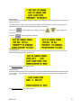
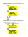
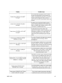
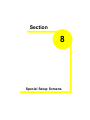
FAN AND HEATER GENERATED ERRORS
The following is a list of errors that are generated with the fan and heater controller. Each fan and heater has there
own set of safeties which are listed below. You will need to inspect the controller associated with the error. Example: If you get this error
it is telling you the problem is with Housing 1 (bottom most fan) High Limit.
Air Switch x Stuck
The air switch contacts have closed prior to the fan starting, indicating a freewheeling blade or improper setting
of the air switch. The message will distinguish between which fan caused the shutdown. This indicates that
12VDC has been lost to terminal J7-09 on the Fan/Heater board.
Fan x Loss of Airflow
This error message is displayed when airflow (air pressure) has been established but was lost for some
reason. This could happen if while during the dryers operation the grain has settled or shrinkage in the grain
columns causing a loss of air pressure in the plenum chamber.
Fan x No Airflow
Contacts in the air switch have never opened due to the fan not turning, or the air switch may need adjustment. The message will distinguish between which fan caused the shutdown.
Flame Loss x
The flame sensor has failed to detect a burner flame which had been established but was lost for some reason
and there is a problem with the flame sensing circuitry or the dryer is not getting burner fuel. The message will
50
PNEG-950
distinguish between which burner caused the shutdown. The reference to the number one (1) is telling you
that it is burner number 1 which is the bottom most fan.
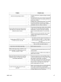
Grain Temp Short x
This error indicates there is a shorted condition with one of the grain temperature sensors located inside the
left or right grain columns. This could be a shorted sensor or the sensor wires could be shorted.
Grain x Overheat
An over temperature condition has occurred in one of the grain columns causing the control to shutdown the
dryer. This control is set at 210°F (99°C) and automatically resets itself when cool. This can be caused from a
grain column plugged with trash or your meter rolls may be adjusted to slow. Feel the grain columns to
determine which one may be causing the problems. If all the columns are hot to the touch then you will
probably need to check your meter roll settings. If not, then examine the column that feels hot, make sure you
can see the grain moving down the column screens. For more information on service see Meter Roll Servicing.
Housing x High Limit
The temperature high limit located on the fan/burner housing has opened, indicating an over temperature
condition has occurred towards the rear of the fan/heater housing. This control is set at 200°F (93°C) and
must be manually reset. The message will distinguish between which fan housing caused the shutdown. The
reference to the number one (1) is telling you that it is fan number 1 which is the bottom most fan.
Ignition Failure x
This condition happens during the intial ignition of the burner. If the burner fails to light, check to make sure
that your gas has been turned on and/or the maxon valve has been turned on. The reference to the number
one (1) is telling you that it is burner number 1 which is the bottom most fan.
PNEG-950
51
Illegal Flame x
This message is displayed when the flame detection circuit of your heater is sensing flame when the burner is
supposed to be off. Example, if you shut down the dryer and the heater continues to burn due to a solenoid
stuck in an open state, it will generate this type of error.
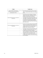
Motor Overload x
One of the thermal overloads on either the fan, load, unload or auxiliary motors has opened, indicating an
overcurrent condition. The overloads must be manually reset. The message will distinguish between which fan
overload caused the shutdown. The reference to the number one (1) is telling you that it is fan number 1 which
is the bottom most fan.
Plenum Temp Open x
This error indicates there is a open condition with the plenum temperature sensor located inside the plenum
chamber. This could be a open sensor or the sensor wires could have a open connection.
Plenum Temp Short x
This error indicates there is a shorted condition with the plenum temperature sensor located inside the plenum
chamber. This could be a shorted sensor or the sensor wires could be shorted.
Plenum x Overheat
An over temperature condition has occurred inside the dryer plenum. This control is a 300°F (149°C) limit and
automatically resets itself when cool. The message will distinguish between which plenum caused the shutdown.
52
PNEG-950
Vapor x High Limit
The LP gas vapor temperature sensor located in the gas pipe train downstream from the vaporizer, has
opened indicating that the vaporizor is running too hot and must be readjusted. This sensor is set at 200°F
(93°C) and automatically resets itself when cool. The message will distinguish between which burner caused
the shutdown. The reference to the number one (1) is telling you that it is burner number 1 which is the bottom
most fan/heater unit, is where the malfunction is located.
Try adjusting the vaporizer coils farther away from the burners flame. You may also want to try switching the
burner mode from Hi/Lo to On/Off, especially on warmer days.
INPUT/OUTPUT GENERATED ERRORS
The following is a list of errors that are generated with the Input/Output board located in the upper control box.
Air System Failure
A shutdown has occurred due to a air system that was installed with an intergal safety switch that was in the
unit. The air system safety connections are located in the upper control box on the terminal strip. This can
occur if this safety looses 12VDC to terminal J2-13 on the I/O board. This input is jumpered on the terminal
strip when it leaves the factory and is usually installed in the field by a qualified electrician.
Aux Load Overload
The motor overload relay has tripped on the Aux Load Motor circuit located in the upper control box. This can
occur if this safety looses 12VDC to terminal J2-10 on the I/O board. Push the red button on the overload to
reset this error. This is caused from the motor operating with to much of a work load, which in turn uses more
current (amperage). If the problem reoccurs then check the motor to make sure it is not being overworked.
You may need to call an electrician to measure the motors full load amps (FLA).
Aux Unload Overload
The motor overload relay has tripped on the Aux Unload Motor circuit located in the upper control box. This
can occur if this safety looses 12VDC to terminal J2-12 on the I/O board. Push the red button on the overload
PNEG-950
53
to reset this error. This is caused from the motor operating with to much of a work load, which in turn uses
more current (amperage). If the problem reoccurs then check the motor to make sure it is not being overworked. You may need to call an electrician to measure the motors full load amps (FLA).
Grain Discharge Warning
The lid on the grain discharge box has opened, indicating that either the grain is not being taken away fast
enough from the discharge box or the take away auger system connected to the dryer may be causing the
problem. This can also occur if this safety looses 12VDC to terminal J2-05 on the I/O board.
Load Motor Overload
The motor overload has tripped on the Load Motor Overload located in the upper control box. This can occur
if this safety looses 12VDC to terminal J2-12 on the I/O board. Push the red button on the overload to reset
this error. This is caused from the motor operating with to much of a work load, which in turn uses more
current (amperage). If the problem reoccurs then check the motor to make sure it is not being overworked.
You may need to call an electrician to measure the motors full load amps (FLA).
Meter Rolls Failed
If you have the meter roll speed adjustment turned too low (not turning), this will cause this error message. It
also could indicate that you have a defective meter roll sensor, the metering roll drive system has failed to turn
or broken chain or jammed metering roll is a possibility. This can occur if the input is not receiving a 5 volt
pulse on terminal J3-03 on the I/O board.
Out of Grain
The dryer has run low on grain, and the out of grain timer has timed out, shutting the dryer down. The unload
auger will continue to run so it can clean out the remaining grain before shutting down.
54
PNEG-950
Unload Motor Overload
The motor overload has tripped on the Unload Motor Overload located in the upper control box. This indicates
that 12VDC has been lost to terminal J2-08 on the I/O board. Push the red button on the overload to reset this
error. This is caused from the motor operating with to much of a work load, which in turn uses more current
(amperage). If the problem reoccurs then check the motor to make sure it is not being overworked. You may
need to call an electrician to measure the motors full load amps (FLA).
User Safety
A shutdown has occurred due to a user installed safety switch that was installed on the dryer. The user
installed safety connections are located in the upper control box on the terminal strip. This also indicates that
12VDC has been lost to terminal J2-01 on the I/O board. This input is jumpered on the terminal strip when it
leaves the factory and is usually installed in the field by a qualified electrician.
MASTER DISPLAY GENERATED ERRORS
The following is a list of errors that are generated with the Master Display board located in the lower control box.
Cont-Batch Mode Chng
This error occurs when you switch the dryer mode switch from the Cont. Flow to the Staged Batch position
while the dryer is running in the Continous Flow Mode. To avoid this shutdown, stop the dryer before switching
modes. Press Stop to clear the error.
Network Failed FH x
This error is generated whenever Fan/Heater board has lost its communications link with the Input/Output
board (upper control panel door) and the Master Display board (lower control panel). Check the blue and
yellow wires marked N1-01 and N1-02 on a 3 terminal plug to make sure they are plugged in tightly. The
reference to the number one (FH1) is telling you that it is fan number 1 which is the bottom most fan.
PNEG-950
55
Network Failed I/O
This error is generated whenever Input/Output board (upper control panel) has lost its communications link
with the master (lower control panel door) and the fan/heater boards. Check the blue and yellow wires marked
N1-01 and N1-02 on a 3 terminal plug to make sure they are plugged in tightly. There are 3 LED lights next to
this plug, one indicates power and the other two indicate data being transmitted. These two labeled RXD and
TXD, should be flashing randomly back and forth indicating network activity.
Network Failed Mast
This error is generated whenever Master Display board (lower control panel) has lost its communications link
with the Input/Output board (upper control panel door) and the fan/heater boards. Check the blue and yellow
wires marked N1-01 and N1-02 on a 3 terminal plug to make sure they are plugged in tightly.
56
PNEG-950
Section
7
Service and Maintanance
Before starting any repairs or maintenance on your dryer, observe the following safety
steps:
1. Isolate the whole system from the electrical supply by switching off the power isolator and locking it.
2. Isolate the dryer from the gas supply by shutting off the main gas valve (if necessary lock the valve).
3. Keep the keys in your possesion.
4. Augers and drives to augers may be under some degree of tension. Avoid touching these parts with your
hands until you are sure that they are free.
5. Do not reconnect the power supply until all work is completed and all guards are correctly refitted.
SEASONAL INSPECTION AND SERVICE
The dryer is made of weather resistant material, and is designed to require a minimum of service. However, each
season we recommend the following items be checked before the unit is used, and any damaged or questionable
parts replaced. These checks will help eliminate possible failures, and assure dependable operation of the equipment.
1. Shut off electrical power. Open power box and control box, and inspect for moisture, rodent damage or accumulated foreign material. Remove any foreign material present. Inspect and tighten any loose terminal connections. Replace any damaged or deteriorated wiring.
2. Check each blade for freedom of rotation and uniform tip clearance. They should also be inspected for dirt and
grain dust, especially inside the hub. Any additional weight can seriously effect the balance, and result in harmful
vibrations and a short bearing life.
3. Check each blade for free play. Any side play is an indication of defective motor bearings, which should be
replaced to prevent a complete motor failure. Make sure motor mount bolts are tight.
4. Motor bearings should be lubricated periodically, depending on operating conditions. Under normal usage it is
desirable to have the motor cleaned, checked and bearings repacked by an authorized service station every two to
three seasons. If the unit is operated continuously through most of the year, this service should be performed each
year.
Note: If on site bearing relubrication is to be performed, see lubrication instructions for ball bearing
motors. To keep motor bearings properly lubricated, and dispel any accumulation of moisture within the
windings, the fan and auger motors should be operated for 15 to 30 minutes each month.
LUBRICATION PROCEDURE
If the motors are equipped with an alemite fitting, clean the tip of the fitting and grease with a grease gun. Use 1 or
2 full strokes on motors in NEMA 215 frame and smaller. Use 2 to 3 strokes on NEMA 254 through NEMA 365
frame. Use 3 to 4 strokes on NEMA 404 frames and larger. On motors having drain plugs, remove drain plug and
operate motor for 20 minutes before replacing drain plug. On motors equipped with slotted head grease screw,
remove screw and apply grease tube to hole. Insert 5 to 8 cm length of grease string into each hole on motors in
NEMA frame and smaller. Insert 8 to 13 cm length on larger motors. On motors having grease drain plugs,
remove plug and operate motor for 20 minutes before replacing drain plug.
SUGGESTED LUBRICANT’s AND SCHEDULES*
* The bearings have been lubricated at the factory, thus no lubrication should be added before start up.
58
PNEG-950
Note: All of the auger and metering roll bearings are lifetime lubricated and do not require service
relubrication.
1. Remove and clean the gas line strainers. Make certain gas valves are closed and that gas is purged from the
system before attempting to disassemble anything.
2. Inspect the collector plate at the top of the burner casting and the burner cup for any accumulation of foreign
material. Clean if required. Foreign material in the burner cup or casting will not burn out and will impair burner
operation.
3. If required, inspect ignitor plug and clean the electrodes. Use an ignition point file to remove carbon and rust
between the electrode surfaces. Ignitor gap should be about 1/4" (3 mm).
4. Inspect flame sensors for possible damage or poor connections. Flame sensor wires must be in good condition.
5. Inspect and manually rotate the top auger paddle assembly. The paddle unit must rotate freely without any
indication of sticking or binding.
6. Inspect the top auger and bottom auger drive lines for proper adjustment and condition. Re adjust line tension
as required.
7. Operate dryer clean out levers, and check clean out hatch mechanism for proper operation. With hatch open,
inspect and remove any accumulation of dirt, fines and foreign material from the bottom auger trough area.
Note: Do not allow high moisture material to collect within the trough area. It may adversely affect metal parts.
8. Inspect entire dryer for loose, worn or damaged parts. Include check of auger flighting, metering rolls and other
internal parts. Check that temperature sensors within air plenum chamber are secured within insulated clamps,
and do not chafe on other metal parts.
9. Make sure all dryer guards and warning decals are securely installed. Make certain guards do not interfere
with moving parts. If guards or warning decals are missing, contact your dealer for a free replacement.
10. Test fire the dryer several weeks ahead of the drying season. Check for possible gas leaks. See burner test
fire section.
FAN BLADE REMOVAL AND INSTALLATION
When working on or around the fan blade, be aware that it may free wheel, and could
cause serious injury. It may be helpful to gently wedge the propeller to prevent this
from occuring. However, do remember to remove the wedge before restarting the fan.
If at any stage the blade has become damaged, it is important that it is repaired and that
the blade is in balance. Failure to do this could result in the blade running out of balance, and potentially exploding. Balancing the blade is a specialists job, if in doubt
contact GSI or your dealer.
The fan blade is secured to the motor shaft by the use of a taper-lock bushing, motor shaft key and three cap
screws.
CAUTION: Although the taper-lock method of retaining the blade onto the motor shaft is simple, it is essential that
the following points be read carefully and fully understood. Improper installation can cause a loose flying blade,
and result in serious injury or death.
PNEG-950
59
FAN REMOVAL AND INSTALLATION
When reassembling parts, the cap screws must be installed through the untapped clearance holes as shown.
This will cause the blade to be pulled forward onto the tapered bushing, thus locking the parts securely onto
the motor shaft.
When fan servicing requires removal and installation of the blade, make sure the blade is removed and
reinstalled properly.
1.
Lock out the fan power supply, and remove the fan guard and the venturi, as required on some models.
2. Remove the three cap screws from the clearance holes in the taper-lock bushing.
60
PNEG-950
3. Install two of the cap screws into the threaded holes in bushing, and turn them by hand until they bottom
against the front surface of the blade. NOTE: The threaded holes within the bushing are provided for disassembly purposes only. Do not attempt to use these holes for reassembly. They will not allow the parts to lock
onto the shaft thereby causing a hazardous operating condition.
4. Block blade to prevent it from turning, and gradually turn the cap screws (up to 1/4 turn at a time) until the
blade breaks loose from the bushing and motor shaft. Carefully remove bushing and blade. With the blade free
from the bushing,a wheel can be used to pull the bushing off of the motor shaft. Re-attach bushing onto blade
to prevent the loss of parts.
Note: During manufacturing, the blade and bushing are balanced together and are marked with two
small dots to identify their original alignment position. Check the bushing and propeller to make sure
they have alignment marks. Mark the alignment of the propeller and bushing, if necessary.
FAN MOTOR REMOVAL
In the event of motor failure, remove the motor as described, and take it to the nearest service station. An authorized service station is the only place that can provide possible motor warranty. Motor service and repair at other
places will be at owners expense.
If the service station determines motor failure is caused by faulty material or workmanship within the warranty
period, repair will be covered under the warranty. Motor failure caused by external sources will result in a charge to
the owner for repair.
1. Make certain power is shut off and locked out. Remove fan guard and blade.
2. Remove cover from fan/heater control box, and disconnect the motor lead wires from within the box.
Note: Tag or otherwise identify wires for ease of reassembly.
3. Remove motor mount bolts. If there are shims between the motor and its base, note their location so they can
be properly installed during reassembly.
4. Disconnect the upper end of the motor conduit, then carefully pull the wires through the hole in the fan/heater
housing. Remove motor from the fan/heater unit with the conduit still attached. If motor requires service, take it to
an authorized service station.
5. To reinstall motor, slide onto motor base plate and replace shims (if required) between motor base and plate.
Reinstall motor mount bolts and washer, but do not fully tighten at this time.
6. Reinstall conduit and wires through hole in fan/heater housing and carefully connect all electrical wiring.
7. Adjust position of motor by temporarily mounting fan blade on motor shaft. Rotate fan blade by hand, making
the necessary adjustments, so the tip clearance between blade and housing is uniform. If required, remove the fan
blade and fully tighten all four motor mount bolts.
Note: Make sure to install and tighten the blade in accordance with previous instructions.
HEATER PARTS REMOVAL AND INSTALLATION
Most of the heater parts can be removed by simply identifying any attached wiring, and then disconnecting the
obvious mounting parts.
1. Flame sensor: Disconnect the wire connector, and unscrew the flame sensor out of its mounting bracket.
2. Gas Solenoid valve coil(s): Unsnap either the plastic cap, or the metal clip on the gas valve, and slide the
housing and coil off the valve stem and body. Do not energize the coil when it is removed, as the coil may become
damaged due to excessive current flow.
3. Regulator and gas solenoid valve(s): The gas regulator and solenoid valve(s) are directional and must be
connected as indicated by the markings near the port openings. Make sure gas is shut off and purged from the
system before removing parts.
PNEG-950
61
Note: When installing a liquid gas solenoid valve on LP models, do not over tighten the connection
into the inlet side, as the inlet orifice may become partially blocked.
4.
Main Gas Orifice: With fuel shut off and gas purged from system, proceed as follows:
a. Disconnect the plumbing support brackets from the pipe train.
b. Disconnect gas solenoid valve coils. Be sure to mark which one goes where.
c. Lift pipe (with orifice, solenoid valve and other parts attached), straight up and remove from fan/heater
housing. Orifice and other parts can now be removed from pipe train, if desired.
5.
Reassemble: To reassemble parts, reverse the disassembly procedure and check the following:
a. Make sure all parts are thoroughly cleaned and open.
b. Use a dependable brand of high temperature pipe caulking compound when assembling gas connections.
Apply only a light coating onto male threaded end of fittings.
c. Solenoid valves and gas regulators are directional and must be properly installed. Do not attempt to connect
gas solenoid valve by applying force to the valve core stem as it may ruin the unit.
d. Make sure all electrical wires are properly connected. Refer to wiring diagrams.
Pressure Guage
Main Solenoid
Firing Valve
Cycle Solenoid
Bypass Valve
Adjustment
Relief Valve
Vapor High Limit
Regulator
LP pipe train.
METER ROLL SERVICING
This dryer is equipped with SCR metering roll drive assembly. The metering rolls are driven by a separate DC type
electric motor. The speed of the motor is variable, and is controlled by an electric SCR control within the main
control box.
MAIN CONTROLS
1. SCR speed control: The metering roll speed pots on the front of the control box regulate the speed of the
DC motor which drives the metering rolls.
62
PNEG-950
The scale of adjustment is from 0 to 999 which represents the flow of grain past the metering rolls as a
percent of the maximum grain discharge rate for the dryer. The maximum setting of 999 provides a maximum
100% discharge of 1960 BPH (50 MT / hr) for 1214, 2240 BPH (57 MT / hr) for 1216, 2520 BPH (64 MT / hr)
for 1218, 2800 BPH (71 MT / hr) for 1220, 3080 BPH (78 MT / hr) for 1222, 3640 BPH (92 MT / hr) for 1226
model dryers.
Note: When the control is set to the maximum discharge rate (999), the metering roll speed should be
17.5 RPM for 8" (20 cm) discharge auger.
2. DC electric motor: The direct current (DC) motor provides the drive for the metering roll, and is located
on the front left hand side of standard model dryers. The output shaft of the motor is connected directly to the
gear box assembly.The DC motor requires no operational adjustment as it is completely controlled from the
control box.
3. Speed reducer gear box: The direct drive gear box providesthe required speed reduction, and transmits
power to the metering rolls through a drive chain arrangement. The gear box does not require adjustment. The
drive chain should also be periodically lubricated and retensioned as necessary.
4. Unload auger time delay: The delay controls the bottom auger system and causes the unload auger (and
any connected auxiliary unloading conveyors) to continue operating for a programmed amount of time, even
after the metering rolls stop. This feature permits the cleanout of grain within the unloading equipment at the
end of all discharge cycles.
5. If a foreign object becomes lodged in the metering rolls and jams the system, the unloading auger will stay
in motion. However, the metering roll drive will stop and the DC motor should stall out. The Network Control
System will shut down the dryer after a two minute period.
To determine if the metering problem is from blockage, perform the following test with the power off. Remove
the drive chain by loosening the motor mounting bolts. Refer to photo, and place a pipe wrench on the hub of
the roller chain sprocket, on the left hand metering roll at the drive end of the dryer. Apply up to 100 ft.lbs. (136
N-m) of force, and attempt to rotate the roll toward the inside of the dryer. If the metering roll will turn, then
repeat for right hand side. If the metering roll will turn, it can be assumed that no blockage exists, and the
problem is from some other cause. Check for a break in the power train, chain, drive key, pin, etc.
CAUTION: Keep hands away from sprocket teeth to avoid injury from chain backlash, as a result of
torsion build up in the system caused by the jam.
HOW TO CLEAR A JAMMED METERING ROLL
Place a pipe wrench on the hub of the sprocket of the jammed metering roll and turn the roll. First, backward,
and then, forward several times in an attempt to dislodge the object, and clear it through the roll. If this is not
successful, have an assistant turn the metering roll, and attempt to locate the jam by sound. Shut down the
fan/heater, and eliminate any other noise when making this check. Once the location is determined, the roll
can be reached from the outside by opening the access door to remove the foreign object causing the jam
(before opening doors see below). The service tool must be inserted before opening doors. First, swing open
the plenum bottom closure panel. Insert the service tool above the metering roll.
PNEG-950
63
This column cutoff damper is designed to insert through the grain column (from the inside of the dryer) immediately above the metering roll. This permits opening of the metering roll access door. For service or inspection
without unloading the dryer, the plenum bottom closure panel and metering roll adjust damper must be removed prior to using service tool.
TROUBLE ANALYSIS PROCEDURE
A multimeter is required for some of the following checkout procedures. Before performing any tests, check if the
dryer power supply is 1 phase, 230 volt, or 3 phase, 230, 380, 460 and 575 volt.
•
•
•
•
•
The burner circuit is 120 volts AC on all standard U. S. production models.
The control circuit to the motor starters is 120 AC volts.
The safety circuit is 12 volts DC
When checking these circuits, measure voltage between the circuit test location and to ground.
DC circuits should be measured between the test location and its respective DC ground.
Refer to wiring diagrams and the parts list for identification of parts and the electrical terminals.
CAUTION: When making high voltage tests with “live” circuits, be extremely careful. Follow
established safety practices. Turn power on for testing only. Do not attempt to make the dryer operate by
using a jumper wire to bypass a defective safety component.
64
PNEG-950
PNEG-950
65
66
PNEG-950
PNEG-950
67
68
PNEG-950
Section
8
Special Setup Screens
By pressing and holding the button while the power is off. Continue to hold and turn on the control power for the
dryer. You will be able to access certain dryer features that rarely need to be changed and if setup incorrectly,
could cause your dryer not to operate properly or not at all.
Pressing will allow you to enter the customer setup screens in the following sequential order:
Meter Roll Disable
Disable Air Switches
Meter Roll Reverse Select
Select Unload Method
Select Dryer Address
Attempt to Refill
Model Number
Temperature Scale Select
Fan and Heater Select
Set Time & Date
Adjustable Grain High Limit
Note: To bypass any or all of these screens without changing the current settings just press .
METER ROLL DISABLE
This option allows you to shut off the monitoring of the meter roll sensor located in the rear of the dryer. This
should be only used in the event of a failure of the sensor itself. This sensor is used for calculation of the bushel
per hour, total bushels and meter roll rpm’s.
To toggle this feature on or off use the
changes.
buttons then press the
button to accept the
AIR SWITCH TESTING
This option allows you to disable the testing of the air switch. This is useful if you are doing a pre season check on
your dryer and you want to start the fan and heater with no grain in the columns or you are having air switch
problems. The computer will ignore the state of the air switch if you change the selection to NO.
To toggle this feature on or off use the
changes.
buttons then press the
button to accept the
Note: If the dryer’s control power is lost, this option will toggle back to its factory state of YES.
METER ROLL REVERSE
This feature allows the meter rolls to temporarily reverse themselves for a programmed amount of time to help
remove any debris that may have built up around this area. This is very useful if you are drying grain with alot of
trash. This will help prevent the grain from not moving in the grain columns then causing the dryer to shutdown
with grain overheat error.
70
PNEG-950
To toggle this feature on or off use the
changes.
buttons then press the
button to accept the
You will activate 2 additional screens by selecting yes.
Reverse time
This screen changes the amount of time you want he meter rolls to run in the reverse (backwards) mode. 5
minutes is the default setting.
Pr ess
to change the reverse time or
to jump to the next screen.
Forward time
This screen changes the amount of time you want he meter rolls to run before switching to the reverse mode.
5 minutes is the default setting.
Pr ess
to change the reverse time or
to jump to the next screen.
Note: This feature is only available on software version 1.03 or higher.
SELECT UNLOAD METHOD
This is a feature that has not been implemented yet into the dryer software, leave this setting at 2 speed. Changing it to 3 speed may cause your dryer unload system to fail.
PNEG-950
71
SELECT DRYER ADDRESS
This feature is used for networking several portable grain dryers together for monitoring on a PC with special
software. Changing this value will have no effect on the operation of the dryer, only the monitoring software
(Watchdog 2000).
ATTEMPT TO REFILL
Changing this setting to yes allows your dryer to pause its drying process in the event that the Out of Grain Timer
has expired. Instead of the dryer shutting down with a Out of Grain error message, the following sequence of
events will happen:
·
·
·
·
Load will continue to run
Fan will continue to run
Burner will stop drying
Unload will stop
The dryer will continue in this mode until the fill switch (paddle switch on the load auger) has changed its state to
indicate the dryer is full of grain again. At this point the dryer will:
·
·
·
·
Load will stop running
Burner will purge and relight to continue drying
Unload will start discharging grain again
Out of Grain timer will reset
MODEL NUMBER
This screen tells the computer in your Network dryer what model of dryer it is. Do not change any information in
this screen unless you are
directed to either by a GSI service technician or engineer.
Just press the
th e
Use the
72
button to advance to the number on the line that needs to be changed or you can use
button toback up to the previous number on the line.
to change the number directly above the cursor “^”. Once you are satisfied with your.
PNEG-950
changes press the
button to accept them.
Note: If the wrong selection is made, your dryer will look for other safeties that will not be present causing
the dryer to be inoperable.
TEMPERATURE SCALE
This screen is used to toggle the temperature scale from Celsius to Fahrenheit. To change the scale
press the
then press the
to accept the changes.
FAN/HEATER SELECT
This screen allows you to change the burner characteristics from a Hi/Lo type of burner to a On/Off type burner.
The On/Off burner mode can be useful when drying on very warm days
which may cause the dryer to never cycle from the Lo cycle.
Pressing the
button will allow you to change the configuration of individual burners from On/Off to Hi/
Lo type burners.
To change the burner mode press
buttons to toggle the burner setting then press the
button to accept the changes.
PNEG-950
73
On this screen you can disable a fan and heater out of the Network loop. This would be used if you have a fan/
heater computer that is malfunctioning and rather than preventing you from using the dryer at all, you can just
ignore it. So you can continue to use your dryer until you can have the dryer serviced. To change the fan/heater to
an inactive state, press the
buttons to toggle between active or inactive. Then press the
button to accept your changes.
IMPORTANT NOTE! It is possible to change all your fan and heaters to an inactive state which would
cause your dryer to be unable to dry grain.
The display screen will then advance to the next fan and heater on your dryer. You can easily configure your dryer
to use both On/Off burners and Hi/Lo burners at the same time. This depends on your particular drying situation.
Possible reasons for using On/Off burner:
•
•
•
•
Low drying temperatures needed (ie. drying popcorn, rice, soybeans)
Very warm outside ambient temperatures
Drying grain that already has low moisture content requiring only 1 to 5 point moisture removal
May help prevent Vapor High Limit shutdowns
Possible reasons for using Hi/Lo burner:
• Higher drying temperatures needed (ie. Hard to dry varieties of corn)
• Colder outside ambient temperatures
• High moisture content grain requiring 5-15 point removal
SET TIME & DATE
Use this screen to set the computers time and date. The time and date is preset at the factory but because of
different time zones you may find the need to change it. Just press the
number on the line that needs to be changed or you can use the
number on the line. Use the
you are satisfied with your changes press the
74
button to advance to the
button to back up to the previous
to change the number directly above the flashing cursor. Once
button to accept them.
PNEG-950
CONTRAST ADJUSTMENT
Press and hold the
the
button while the control power is off, then turn the control power on, then release
button. Press the
buttons to darken or lighten the contrast. Press the
to accept the changes.
Note: If the display is blank, keep pressing the increase button to bring up the contrast. A new installed
display board may not have had the contrast set at the factory and defaults at no contrast.
PNEG-950
75
76
PNEG-950
Section
9
Drying Charts
1200 Series Dryers
1200 Continuous Full Heat
78
PNEG-950
1200 Continuous Dry & Cool
PNEG-950
79
1200 Staged Batch
80
PNEG-950
1200S 50/50 Split Dryers
1200S Continuous Full Heat
PNEG-950
81
1200S Continuous Dry & Cool
82
PNEG-950
1200S Staged Batch
PNEG-950
83
84
PNEG-950
Section
10
Technical Reference
CONTROL PANEL JUMPER WIRING
Note: Wiring specifications are subject to change without notice.
86
PNEG-950
CONTROL PANEL INTERNAL WIRING
PNEG-950
87
LOWER CONTROL BOX BACK PANEL WIRING
88
PNEG-950
NETWORK FAN/HEATER INTERFACE
GREEN - ELECTRICAL GROUND
BLUE - N1 NETWORK
YELLOW - N2 NETWORK
WHITE - 110VAC NEUTRAL
BLACK - 110VAC POWER
WHITE - GRAIN TEMPERATURE SENSORS 2 WIRES
BLACK - GRAIN TEMPERATURE SENSORS 2 WIRES
YELLOW - GRAIN HI LIMIT SWITCH
YELLOW - GRAIN HI LIMIT SWITCH
ORANGE - GRAIN HI LIMIT SWITCH
ORANGE - GRAIN HI LIMIT SWITCH
WHITE - PLENUM TEMPERATURE SENSOR
BLACK - PLENUM TEMPERATURE SENSOR
GREY - PLENUM HI LIMIT SWITCH +12VDC
GREY - PLENUM HI LIMIT SWITCH +12VDC
WHITE - SOLENOID NEUTRAL - 110VAC NEUTRAL
GREY - LP LIQUID SOLENOID - 110VAC
BLACK - MAIN SOLENOID - 110VAC
BROWN - CYCLE SOLENOID - 110VAC
GREEN - ELECTRICAL GROUND
YELLOW - HOUSING HI LIMIT
YELLOW - HOUSING HI LIMIT
PURPLE - VAPOR HI LIMIT
PURPLE - VAPOR HI LIMIT
BLUE - AIRSWITCH COMMON - DC NEGATIVE TP
BLUE - AIRSWITCH NORMALLY OPEN
RED - MOTOR OVERLOAD +12VDC
RED - MOTOR OVERLOAD +12VDC
WHITE - 110VAC NEUTRAL FOR FAN BOX
BLACK - STARTER COIL - 110VAC
BROWN - IGNITION TRANFORMER - 110VAC
WHITE - FLAME PROBE GROUND (HI TEMP)
RED - FLAME PROBE TIP WIRE (HI TEMP)
GREEN - ELECTRICAL GROUND
ADD J7-17 RED
ADD J7-06 PINK
- CANADIAN ONLY
89
PNEG-950
NEXT FAN
CONTROLLER
UPPER CONTROL
BOX
GRAIN HI LIMIT
JUNCTION BOX
PLENUM
SENSOR BOX
SOLENOIDS
HOUSING
HI LIMIT
BOX
FAN
BOX
FAN COMPUTER PINOUTS
90
PNEG-950
FAN CONTROL BOX
PNEG-950
91
UPPER TERMINAL STRIP
92
PNEG-950
UPPER BACK PANEL CONTROL WIRING
PNEG-950
93
NOTES
______________________________________________________________________________________________________
_______________________________________________________________________________________________________
______________________________________________________________________________________________________
__________________________________________________________________________________________________________
___________________________________________________________________________________________________________
__________________________________________________________________________________________________________
________________________________________________________________________________________________________
__________________________________________________________________________________________________________
_________________________________________________________________________________________________________
_______________________________________________________________________________________________________
_________________________________________________________________________________________________________
_______________________________________________________________________________________________________
__________________________________________________________________________________________________
___________________________________________________________________________________________________
_____________________________________________________________________________________________________
____________________________________________________________________________________________________
________________________________________________________________________________________________________
_______________________________________________________________________________________________________
________________________________________________________________________________________________________
_________________________________________________________________________________________________________
________________________________________________________________________________________________________
______________________________________________________________________________________________________
________________________________________________________________________________________________________
____________________________________________________________________________________________________
_______________________________________________________________________________________________________
______________________________________________________________________________________________________
___________________________________________________________________________________________________________
94
PNEG-950
NOTES
______________________________________________________________________________________________________
_______________________________________________________________________________________________________
______________________________________________________________________________________________________
__________________________________________________________________________________________________________
___________________________________________________________________________________________________________
__________________________________________________________________________________________________________
________________________________________________________________________________________________________
__________________________________________________________________________________________________________
_________________________________________________________________________________________________________
_______________________________________________________________________________________________________
_________________________________________________________________________________________________________
_______________________________________________________________________________________________________
__________________________________________________________________________________________________
___________________________________________________________________________________________________
_____________________________________________________________________________________________________
____________________________________________________________________________________________________
________________________________________________________________________________________________________
_______________________________________________________________________________________________________
________________________________________________________________________________________________________
_________________________________________________________________________________________________________
________________________________________________________________________________________________________
______________________________________________________________________________________________________
________________________________________________________________________________________________________
____________________________________________________________________________________________________
_______________________________________________________________________________________________________
______________________________________________________________________________________________________
___________________________________________________________________________________________________________
PNEG-950
95
This Equipment shall be installed in accordance
with the current installation codes and applicable
regulations which should be carefully followed in
all cases. Authorities having jurisdiction should be
consulted before installation occurs.
The GSI Group, Inc.
1004 E. Illinois St.
Assumption, IL 62510-0020
Phone: 217-226-4421
Fax: 217-226-4420
e-mail: [email protected]
internet: http://www.grainsystems.com
Copyright © 2006 by The GSI Group
Printed in the USA