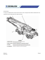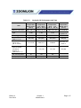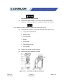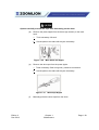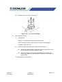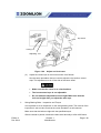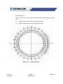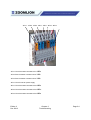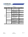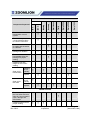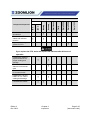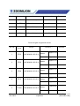
1
MAINTENANCE MANUAL FOR
ROUGH TERRAIN CRANE
Address:Quantang Indust=rial Park, 2nd Yuanda Road,
Changsha Economic and Technological Development
Zone, Hunan Province, China
Postcode: 410131
Website: www.zoomlion.com
MAINTENANCE
MANUAL
Edition 1
Dec 2013
Dec 2013
(Thank you letter)
Owners, Users and Operators:
Zoomlion Cranes appreciates your selection of the ZOOMLION Rough Terrain Crane for your
application.
No one should do the maintenance/service tasks to the crane unless they read and know the
data in this manual and the other technical documents supplied with the crane.
The Maintenance and Service Manual provides periodic inspections, maintenance and service
procedures that are necessary to make sure the performance, safety and reliability are at the
highest level. They can also increase the service life of the crane.
When you follow the instructions in this manual, your crane can operate at MAXIMUM
EFFICIENCY.
To look after your rights & interests and safety, you must obey all safety data in the
Maintenance and Service Manual. Only approved personnel can disassemble and adjust
hydraulic system components during maintenance. When a hydraulic component malfunctions
or is damaged, tell the local repair facility.
You do not have to keep the Maintenance & Service Manual in the cab of the crane. The
Maintenance & Service Manual must be with the crane if it is sold.
If there is something in the manual that you do not understand, speak with us. We (Zoomlion
Cranes) are NOT responsible for damages from an operator or service technician who does not
obey the instructions in the Maintenance and Service Manual.
THANK YOU!
Mobile Crane Branch Company of ZOOMLION Heavy Industry Science and Technology Co.,
Ltd
Copyright
Under the copyright laws, this manual cannot be copied, photocopied, reproduced, translated, or reduced to any electronic medium
or machine readable form, in whole or part, without the prior written consent of Zoomlion Heavy Industry Science and Technology
Co., Ltd.
Copyright © 20XX, Zoomlion Heavy Industry Science and Technology Co., Ltd.
All rights reserved. Printed in the United States
Edition 2
Dec/2013
Page i
Edition 2
Dec/2013
Page ii
Contents
(Thank you letter)......................................................................................................................... i
Contents .................................................................................................................................... iii
About This Manual ...................................................................................................................... v
Safety ....................................................................................................................................... vii
Intro duction ............................................................................................................................ 1
1.1
INTRODUCTION ....................................................................................................... 1
1.2
OPERATOR OBSERVATION .................................................................................... 1
1.3
WIRE-ROPE INSPECTION RECORD ....................................................................... 3
1.4
ENGINE MAINTENANCE .......................................................................................... 4
1.5
ENGINE RADIATOR MAINTENANCE....................................................................... 7
1.6
TRANSMISSION MAINTENANCE ............................................................................ 8
1.7
AXLE MAINTENANCE CHECK ............................................................................... 10
1.8
TIRE MAINTENANCE CHECK ................................................................................ 11
1.9
BRAKE SYSTEM MAINTENANCE .......................................................................... 14
1.10
AIR SYSTEM MAINTENANCE ................................................................................ 15
1.11
BATTERY MAINTENANCE ..................................................................................... 15
1.12
FUEL, COOLANT AND TORQUE CONVERTER HYDRAULIC TRANSMISSION
OIL .......................................................................................................................... 16
1.13
LUBRICATION ........................................................................................................ 17
1.14
HYDRAULIC OIL ..................................................................................................... 24
1.15
GEAR OIL ............................................................................................................... 28
1.16
LUBRICATING GREASE......................................................................................... 30
1.17
LUBRICATING POINTS .......................................................................................... 31
1.18
ADJUST, CLEAN AND REPLACE THE PARTS ...................................................... 33
1.19
BATTERY MAINTENANCE AND SERVICE ............................................................ 50
1.20
BATTERY MAINTENANCE – WINTER ................................................................... 51
1.21
OPERATION IN WINTER ........................................................................................ 52
1.22
OPERATION IN SUMMER ...................................................................................... 53
Troubleshooting .......................................................................................................................... 1
Edition 2
Dec/2013
Page iii
2.1
ELECTRICAL SYSTEM............................................................................................. 1
2.2
HYDRAULIC SYSTEM ............................................................................................ 12
2.3
EXTEND / RETRACT SYSTEM............................................................................... 13
2.4
DERRICKING MECHANISM ................................................................................... 14
2.5
SWING MECHANISM ............................................................................................. 15
2.6
HOIST MECHANISM............................................................................................... 16
2.7
OUTRIGGERS ........................................................................................................ 17
2.8
TRANSMISSION ..................................................................................................... 18
2.9
BRAKE SYSTEM .................................................................................................... 21
2.10
STEERING SYSTEM .............................................................................................. 22
2.11
FRONT / REAR AXLES........................................................................................... 25
2.12
DRIVE SHAFT ......................................................................................................... 27
2.13
TIRES...................................................................................................................... 28
2.14
ENGINE ERROR CODE.......................................................................................... 30
2.15
TRANSMISSION ERROR CODE ........................................................................... 40
Inspection ................................................................................................................................. 84
3.1
PRE-START INSPECTION ..................................................................................... 84
3.2
NEW CRANE SPECIAL BREAK-IN REQUIREMENTS ........................................... 88
3.3
PERIODIC INSPECTIONS AND SERVICE ............................................................. 88
3.4
PERIODIC CRANE INSPECTIONS......................................................................... 96
3.5
INSPECTIONS AND MAINTENANCES DURING BREAK-IN PERIOD.................. 103
3.6
FILTER ELEMENTS LISTS ................................................................................... 104
3.7
FLUID VOLUME REQUIREMENTS ...................................................................... 106
Edition 2
Dec/2013
Page iv
About This Manual
General
The data (data, specifications, illustrations) in this manual is for cranes in production at the time of this
manuals publication. We reserve the right to make changes to this manual at any time, without obligation.
This manual is for maintaining and servicing the RT Crane in the field. Follow the operation and
maintenance procedures to make sure that your machine operates at MAXIMUM EFFICIENCY. Use the
CRANE PERIODIC INSPECTION CHECKLIST. Keep a maintenance log to monitor all maintenance
work on the machine.
An example of a Maintenance Log and Crane Periodic Inspection Checklist is at the end of this section.
Again, we at ZOOMLION appreciate your selection of our crane. User safety is most important. To
complete on-site tasks safely, operators and service technicians must be responsible. Obey the
instructions that follow:
Edition 2
Dec /2013
•
Comply - with Occupational Safety and Health Administration (OSHA), Federal,
State and Local Regulations.
•
Read, Understand and Follow - the instructions in this and other manuals and
documents that come with the crane.
•
Use Good, Safe Work Practices - in a common sense way.
•
Only have trained operators and service technicians - directed by informed
and knowledgeable job-site supervisors.
•
Do not use this crane - before the portable fire extinguisher, installed in the cab,
agrees with local fire protection rules.
Page v
OSHA prohibits the alteration or modification of this crane without written
manufacturer’s approval. Use only the factory approved parts to service or repair
the crane.
If you make modifications/additions which affect the safe operation of the
equipment to the crane before you use it, the crane owner must make sure that the
modifications/additions agree with OSHA 1926:1412.
Speak with us if special data is necessary for the maintenance or operation of your RT Crane. Send your
machine model and a serial number to make sure that you receive the correct data.
If there is anything in this manual that is not clear or which you think is necessary, write to the address
that follows:
Rough Terrain Crane R & D Institute
Zoomlion Mobile Crane Branch Company
Quantang Industrial Park, 2nd Yuanda Road,
Economic and Technological Development Zone,
Changsha, Hunan Province, China, 410131
You can also speak to us by telephone at 0086-84671997 (international), 0731-84671997 (in China).
Thank You!
Edition 2
Dec /2013
Page vi
Safety
The safety symbol, used on the Danger, Warning and Caution labels, tells personnel of possible death,
injury, or property damage. Obey all safety data that follows this symbol to prevent dangerous conditions.
HAZARD CLASSIFICATION
Hazard classification is a system to show different classes of possible injury levels. A safety symbol and
a signal word show how dangerous the level of possible injury can be.
A signal word without a safety symbol refers to property damage, protection devices, or important data.
You will find this system used in this manual and on signs on the crane to help find and prevent
dangerous situations.
HAZARD INDICATORS
DANGER, WARNING, CAUTION and NOTE labels are on signs and decals and as you read this manual
to show important instructions. In this manual, DANGER, WARNING and CAUTION labels are before the
paragraph or item to which they apply. NOTEs follow the paragraph or item they apply to. The labels are
as follows:
Refers to a dangerous situation which, if you do not prevent, will cause death or injury.
Refers to a possible dangerous situation which, if you do not prevent, could cause death or injury.
Refers to a possible dangerous situation which, if you do not prevent, may cause light or moderate injury.
Refers to a tip or hint in the instructions.
INTENDED USE
Edition 2
Dec /2013
Page vii
Scope
The owner of this crane must know federal, state and local rules. When your equipment is in operation, the
area must be safe for employees and non-employees. Do not cause damage to other equipment or local
structures while you operate this crane. Rules change by location and this manual does not give that data.
ZOOMLION makes manuals for different construction and industrial equipment. It is policy to include
applicable national consensus, industry standards and safety data with the manuals. Use this data to give
applicable training to personnel who are to operate, do the maintenance and supervise the equipment
correctly and safely.
We make equipment for heavy-duty labor. Do periodic inspections regularly because the equipment wears
during operation. This prevents accidents, decreases downtime and helps equipment work satisfactorily. The
goal of these inspections is to find worn, cracked, damaged parts and loose or missing fasteners before they
cause a problem.
Correct training and inspection procedures are necessary to prevent injury to persons, property damage and
high maintenance costs.
Read and understand the data that comes with this crane. Help is available from the distributors of your
ZOOMLION crane and from the ZOOMLION manufacturing facility.
This manual contains the instructions and data on the operation, maintenance, lubrication and adjustments of
the Rough Terrain Crane. Do not operate or service the crane before you understand the data in this manual.
Edition 2
Dec /2013
Page viii
Nomenclature
To help you understand the contents of this manual, refer to the figure below. Each numbered term can
represent several components of the same main part.
Edition 2
Dec /2013
Page ix
CRANE PERIODIC INSPECTION CHECKLIST
Edition 2
Dec /2013
Maintenance
Condition
Adjusting
Condition
Function
Inspection
Code
Component
Inspected
Maintenance
Condition
Adjusting
Condition
Function
Interval
Component
Inspected
This inspection checklist provides supplementary data to facilitate the correct operation and maintenance
of the crane.
Page x
MAINTENANCE LOG
Item
Edition 2
Dec /2013
Adjusting Condition
Date
Page xi
Edition 2
Dec /2013
Page xii
MAINTENANCE AND SERVICE MANUAL FOR ROUGH TERRAIN CRANE
Chapter 1 Maintenance and Service
Introduction
1.1
INTRODUCTION
A set of preventive maintenance tasks is necessary to extend the serviceable life of
the crane. The tasks can help to maximize efficient service and decrease the time
the crane is at the repair facility. This section has checks and procedures which you
are to do on daily, weekly, monthly and semi-annual intervals. These intervals are
specified in conditions of calendar and hours of operation.
The checks for long intervals include all the checks that you do in the shorter
intervals. Thus, the weekly check includes all items in the daily check. The monthly
check includes the weekly and the daily checks. The semi-annual check includes the
quarterly, monthly, weekly and daily checks.
The chart makes it possible for you to record the preventive maintenance tasks that
you complete. It also supplies you with a tool to find the problem areas and to
examine the value of the maintenance tasks. The items in each check interval on the
chart are assembled by their applicable headings and explained in this chapter.
This maintenance schedule is a procedure to make sure that basic preventive
maintenance tasks are completed in the usual conditions that you operate. The
conditions which increase wear, loads or strain on the crane, usually make it
necessary to decrease the interval time. Before you change the maintenance
schedule, examine your operation and the maintenance records of the crane. Think
about all the factors involved and make a new schedule that is sufficient to align the
usual maintenance tasks.
As a part of each preventive maintenance check, refer to the Engine Manufacturer’s
Manual for engine maintenance tasks. When you do the servicing of the engine, use
the data in the engine manual if this chapter has data that is different.
1.2
OPERATOR OBSERVATION
A.
B.
Edition 2
Dec /2013
Do a visual inspection for:
(1)
Unusual conditions
(2)
Hydraulic system leaks or damage.
Examine the area around the engine for:
(1)
Belts (tension and wear)
(2)
Coolant level
(3)
Engine oil level
(4)
Hydraulic transmission oil level
Chapter 1
Maintenance
Page 1-1
Edition 2
Dec /2013
(5)
Air cleaner vacuum actuated indicator
(6)
Air inlet
(7)
Silencer and exhaust device.
C.
Examine the condition of each battery.
D.
Examine the boom for:
(1)
Sheave (wear or damage)
(2)
The function of the anti-two block system
(3)
Wire-rope on the winches (wear and breaks)
(4)
Wear of the cylinder pin.
E.
Tires, axles and drivelines (wear or damage).
F.
Examine the cab for:
(1)
Gauge and indicator functions
(2)
Function of the switches and joysticks
(3)
Clear windows
(4)
Safety device in position
(5)
Each light operates
(6)
Cleanliness: free from dirt, mud and waste material.
Chapter 1
Maintenance
Page 1-2
1.3
WIRE-ROPE INSPECTION RECORD
WIRE-ROPE INSPECTION RECORD
(See pages 1-37 and 1-38)
Place of inspection ________________________
Date _______________
DESCRIPTION OF CRANE
Make
_____________________________ Model_________
Serial No. ___________
Type and Arrangement of Attachments ___________________________________________
Date of Last Rope Inspection __________________________________________________
Hours and Time of Service Since Last Inspection ___________________________________
RESULT OF INSPECTION
Rope Inspected
Type and Size
Conditions noted
Recommendations
_________________________________________________________________________
_________________________________________________________________________
_________________________________________________________________________
_________________________________________________________________________
_________________________________________________________________________
_________________________________________________________________________
___________________ Inspector:
Edition 2
Dec /2013
Chapter 1
Maintenance
Page 1-3
1.4
ENGINE MAINTENANCE
For Cummins engine maintenance, refer to the EngineManufacturer’s Manual.
Engine productivity, longevity and low-cost performance depend on a regular
program of periodic maintenance. The materials presented here are listed in
accordance with the EngineManufacturer’s Manual. Consideration may dictate a
revision in scheduling for the periodic checks.
A good periodic preventive maintenance program can increase the productivity,
longevity and low-cost performance of the engine. The data, in this section of the
manual, is from the data in the EngineManufacturer’s Manual. You can change the
interval or schedule of the preventive maintenance program because of the area and
the types of operations you do.
A.
Daily Inspections:
(1)
Fuel Level
(a)
You can find the fuel tank on the left side of the crane (Figure 1-1). If
you keep the tank full of fuel, in cold weather, you can decrease the
quantity of condensation.
Figure 1-1
(b)
Edition 2
Dec /2013
Fuel Tank Cap
Use a good grade of diesel fuel. The tank capacity is 79 gal. (300 l).
Chapter 1
Maintenance
Page 1-4
(2)
Engine Oil Level
(a)
You can measure the level of oil in the engine by a dipstick. The
dipstick is on the right side of the engine (aft end of the crane). The
engine must be OFF and sit for a short time before you can
measure the oil level. Wait for 15 minutes, after you stop the engine,
to measure the level. Adjust the level of oil to the full mark.
(b)
Do not overfill!
Do not operate the crane if the level of engine oil is too low or too high.
(3)
(4)
Water Separator
(a)
The fuel line contains a water separator. It removes the
condensation and contamination from the fuel before it goes into the
engine. You must examine the water separator before you operate
the crane to drain the condensation and contamination.
(b)
Do not let the water separator fill more than 1/2 full.
Air Filter
(a)
Examine the air filter and its connections for leaks, dents and
damage (See Figure 1-2).
Figure 1-2
Edition 2
Dec /2013
Air Filter
Chapter 1
Maintenance
Page 1-5
Figure 1-3
(b)
Indicator
A vacuum actuated indicator (See Figure 1-3) is attached on the
side of the air filter assembly. Its gives you an indication of restricted
airflow through the air filter. The quantity of airflow shows on the
indicator at three different levels. When the light is in the green area,
the air filter is good. If the light is in the yellow area, you need to
clean or replace the filter cartridge. If the light is in red area, do not
operate the engine. Replace or clean the filter cartridge. Examine
the intake screen and cartridge area.Make sure that they are clean.
When you use a degreasing agent to clean the engine, make sure that
you put a protective material around the vacuum actuated indicator
(filter minder). The polycarbonate base of the engine degreasing
solvents can damage or destroy the indicator.
(5)
(c)
Reset the air cleaner indicator each time after the filter element is
replaced to assure proper function.
(d)
After you do the servicing on the air filter assembly, reset the
indicator.
Engine Belts
(a)
Edition 2
Dec /2013
Examine the engine belts for condition and correct adjustment.
Refer to the Engine Manufacturer’s Manual for the belt tension and
the correct procedure to make the belts tight.
Chapter 1
Maintenance
Page 1-6
B.
Quarterly Inspection
(1)
Fuel Tank
(a)
(b)
C.
Drain the collected water and sediment from the fuel tank.
•
Remove the drain plug and let the tank drain.
•
Stop the flow when the fuel is clear of water and sediment.
If the tank has a large quantity of sediment, do the task that follows:
•
Fully drain the tank.
•
Flush the tank with kerosene until you remove all the sediment.
•
Fully drain the kerosene and refuel the tank.
Semi-Annually Inspection
(1)
Crankcase Breather
To do servicing on the crankcase breather, follow the procedure in the
Engine Manufacturer’s Manual.
1.5
ENGINE RADIATOR MAINTENANCE
A.
Daily / 8 Hours:
(1)
Edition 2
Dec /2013
Coolant Level
(a)
Insert the engine radiator coolant level and add coolant to adjust the
level. You can see the level of coolant in the sight gauge near the
top of the radiator tank. A solution of 50% ethylene glycol by volume
is the recommended year-round coolant mixture. If necessary, refill
the corrosion inhibitor. Refer to the engine manual or the servicing
facility to pick the correct coolant and corrosion inhibitor.
(b)
If you operate in an area that does not freeze, use a solution of
clean water with a corrosion inhibitor. This gives you the best
performance.
Chapter 1
Maintenance
Page 1-7
B.
Monthly / 160 Hours:
(1)
Radiator Exterior
Clean the radiator fins and through-core cooling passages. Use
compressed air and water in the opposite direction of usual air flow to
push the unwanted material out of the radiator core.
C.
Quarterly:
(1)
Corrosion Inhibitor
Adjust the cooling system corrosion inhibitor to the correct level after 500
hours of operation.
Do not use a chromate based corrosion inhibitor when the coolant in
the system contains ethylene glycol. Only use non-chromate based
inhibitors. The chromate base inhibitorreacts with ethylene glycol to
make hydroxide. This you know as Green Slime. The slime decreases
the heat movement rate and can cause the engine to be too hot.
D.
Semi-Annually:
(1)
Cooling System
Clean the cooling systemat 1000 hours or semi-annually whichevercomes
first. Use a radiator cleaning compound and follow the instructions on the
container. Flush the system with clean water and fill it with an ethylene
glycol solution of 50% by volume.
1.6
TRANSMISSION MAINTENANCE
A.
Edition 2
Dec /2013
Daily Maintenance Check
(1)
Before you move the crane, make sure that the level of oil in the
transmission is correct.
(2)
Start the engine and let it idle at 1000 to 1500 rpm until the transmission
increases to a temperature of 180° F to 200° F (82.2° C to 93.3° C).
When the engine is at the correct temperature, slowly move the shift lever
through all the gear positions. This moves oil to all parts of the system.
Set the shift lever to the neutral position and set the engine speed at idle
rpm.
Chapter 1
Maintenance
Page 1-8
B.
Service the Transmission After Overhaul
When you service the crane for the first time after vehicle installation and / or
after repair, fill the unit as follows:
(1)
Fill the transmission with recommended lubricant.
(2)
Start the engine and set the speed at idle to let oil fill the torque converter
and lines. Stop the engine after 3 minutes.
(3)
Adjust the level of transmission oil as follows:
(a)
Find and remove the oil level plugs on the lower part of the
transmission case on the right side of the crane.
Figure 1-4
Low and High Level Plugs
There are two taper pipe thread oil level holes. One is the low level plug
and the other one is the full level plug.
Edition 2
Dec /2013
(b)
Add the transmission oil until it flows out of the low level plug hole.
(c)
Start the engine at idle speed to let the oil flow through the torque
converter, oil cooler and lines. Check the oil level. Add transmission
oil until it flows out of the low level plug. Install the low level plug.
(d)
Let the oil temperature increase to between 180° F and 200° F (82.2°
C and 93.3° C). Add oil until it flows out of the full level plug. Install
the full level plug.
Chapter 1
Maintenance
Page 1-9
(e)
(4)
C.
Always do the transmission oil level checks with the speed of the
engine at idle. The transmission must be in the neutral position and
the transmission temperature between 180° F and 200° F (82.2° C
and 93.3° C).
Do not put too much fluid in the transmission!
Lubricant and Filter Change Interval
(1)
Refer to Section 1.13 for the lubrication schedule.
(2)
Use the Dana-Clark Filter.
(3)
Change the hydraulic transmission oil and filter after the first 50 hours of
transmission operation. After the first transmission oil and filter change,
the change interval is 500 hours or 3 months of operation. Change the
lubricant at the 1000 hours or 6 months of operation point.
When you operate in cold weather areas or at the initial startup, the
transmission oil is cold and thick. This can cause the oil to intermittently
bypass the filter.
1.7
AXLE MAINTENANCE CHECK
A.
Monthly
(1)
Examine the wheel end oil level as follows:
(a)
Move each wheel until the planet gear cover is at the position in
Figure 1-5. The arrow on the planet gear cover points horizontally
when the cover is at the correct position. Make sure that the oil is at
the correct level.
Figure 1-5
Edition 2
Dec /2013
Wheel End
Chapter 1
Maintenance
Page 1-10
(b)
(2)
Check the differential oil level by removing the filler and check plug
indicated in Figure 1-6. Add oil as necessary to bring the oil level to
the bottom of the hole.
Do a check of the level of differential oil as follows:
(a)
Remove the fill plug.
(b)
Make sure that you can see oil at the bottom of the plug hole.
(c)
If necessary, add oil until it comes out of the fill plug hole.
(d)
Install the fill plug.
Figure 1-6
B.
Annually
(1)
1.8
Remove and replace the oil in the differential as follows:
(a)
Remove the fill plug and the check plug to drain the oil. Refer to
Figure 1-6.
(b)
Make sure that you can see oil at the bottom of the plug hole.
(c)
If necessary, add oil until it comes out of the fill plug hole.
(d)
Install the fill plug.
TIRE MAINTENANCE CHECK
A.
Weekly
(1)
Edition 2
Dec /2013
Differential Plugs
Examine the tires and rims for the items that follow:
(a)
Damage
(b)
Cuts and bruises
(c)
Cracks
Chapter 1
Maintenance
Page 1-11
B.
(d)
Punctures
(e)
Abrasion.
(2)
If necessary, make sure that you repair these items.
(3)
Replace or repair the wheels if they are bent, contain a crack or are loose.
(4)
Make sure that the wheel nuts are correctly tightened.
Tire Pressures
(1)
Always keep the correct tire pressure in all the tires.
(2)
Friction makes heat that increases the pressure in the tires when you
move the crane. Movement at high speeds also increases the pressures
in the tires. Do not deflate the tires if these conditions occur. Decrease
your speed or stop until the pressure decreases.
(3)
Always use an accurate tire pressure gauge. You must measure the tire
pressure when the tires are cool. Do a check of the pressures at regular
intervals.
Because of the explosive nature (high temperature and high pressure)
of the tire and rim it is dangerous to change a tire if you are not trained.
Death or personal injury can occur while you touch or do the
maintenance work on these tires. You must follow special procedures
and use special tools to safely change the tires. If it is possible, let your
repair company do this work. If you must change a tire, follow the step
by step instructions in a Tire Repair Manual. If you must add air
because of low pressure, do not be adjacent to the tire tread. Use a long
extension hose to be behind the tire tread. Always use a tire cage or
equivalent protection when you add air.
(4)
Edition 2
Dec /2013
Do not deflate air from a hot tire. The pressure lowers but the
temperature increases when the tire continues to move. This increase in
temperature causes the tire to malfunction.
Chapter 1
Maintenance
Page 1-12
(5)
Under Inflation
The tires that do not have a sufficient quantity of pressure in them cause
them to wipe and scuff over the road. Strain on the tire increases the
chance to bruise.
(6)
Correct Inflation
When the tires have the correct pressure in them, they do not wear too
quickly.
(7)
Over Inflation
When the tires have too much pressure in them, they do not touch the
surface of the ground correctly. When this occurs, the tires touch the
ground on the crown of the tires and quickly wear in the middle.
Edition 2
Dec /2013
Figure 1-7
Correct Way
Figure 1-8
Wrong Way
Chapter 1
Maintenance
Page 1-13
C.
Tire Change Safety Precautions
When you must make the repair on a wheel (demount and mount the rim and
tire), follow these precautions:
DO:
(1)
Follow the procedures (assemble and disassemble) that you find in the
tire change safety guidelines or other instruction manual.
(2)
Before you start to disassemble the wheel, fully deflate the tire.
(3)
Replace the parts with damage, cracks, signs of wear and corrosion.
(4)
Before you inflate the tire, make sure that you examine the removable
ring. It must be seated correctly.
(5)
Examine the side ring and make sure that it is not too loose. This is an
indication of parts that do not match correctly.
(6)
Do not inflate the tire until the safety cage is in position.
(7)
After you inflate the tire, make sure that the rim ring clearance is between
0.06 in. to 0.25 in. (1.6 mm to 6.3 mm).
(8)
After you complete the repair, examine the wheel nuts and rim clamps for
wear, corrosion, proper centering and the correct torque.
DO NOT:
1.9
(1)
Mix the parts. This is a dangerous condition. Make sure that the side ring
and lock ring agree with the identification marks on the base.
(2)
Lift a load or move a load that is above the capacity of the crane.
(3)
Inflate a tire if it is fully flat or near flat. You must first disassemble and
examine the tire and rim assembly.
(4)
Use a tire and rim configuration that is not approved by the Tire & Rim
Association (TRA).
BRAKE SYSTEM MAINTENANCE
A.
Brake Pedal
(1)
Edition 2
Dec /2013
Routine Maintenance
(a)
Usually the brake pedal is a maintenance free part.
(b)
Make sure that the brake pedal moves freely before you move the
crane.
Chapter 1
Maintenance
Page 1-14
(c)
Examine the brake pedal annually and replace the parts that show
wear or damage.
If you push the service brake pedal and the distance to stop is more than
usual, the system can have a malfunction. When the service brake indicator
illuminates, the pressure in the system can be low. In that condition, do the
necessary steps to correct the condition or send the crane to the repair facility.
Do not move the crane if the indicator stays illuminated.
B.
Park Brake
(1)
Routine Maintenance
Usually the park pedal is a maintenance free part.
1.10
AIR SYSTEM MAINTENANCE
When the air system does not supply the usual quantity of air, look at the items that
follow to correct the condition:
•
Defective components
•
System leak
•
Blocked lines
•
Moisture and sediment in the system.
A good preventive maintenance program is a necessary part of the air system
operation. Refer to the maintenance schedule in this manual. You can change the
interval between checks if the conditions and weather are hard on the equipment.
1.11
BATTERY MAINTENANCE
A.
Edition 2
Dec /2013
Examine the batteries and the area around the batteries as follows:
(1)
Make sure that the terminal connections are tight.
(2)
Remove dirt and corrosion from the wires and terminals.
(3)
Clean the battery area with soda water or pure water. When the terminals
dry, apply Vaseline to them.
Chapter 1
Maintenance
Page 1-15
Figure 1-9
1.12
Battery
FUEL, COOLANT AND TORQUE CONVERTER HYDRAULIC TRANSMISSION OIL
A.
Fuel Selection
(1)
Always use the correct light diesel fuel and engine oil. Make your
selection on the lowest ambient temperature where you are to do the
work.
(2)
Refer to the Operator’s Manual for the fuel sulfur content standards.
(3)
Refer to the Service and Maintenance Manual for the Engine when it is
necessary to put oil into the engine.
Do not use fuel which is mixed with lubricant or other chemicals.
Make sure that the fuel you use in the crane has the correct thickness.
Make your selection on the lowest temperature you operate in.
Make sure that the fuel tank is full. Condensation, rust and sediment
can freeze and cause a blockage in the flow of fuel. The engine cannot
start if the fuel does not flow or flows too slowly.
B.
Coolant Selection
We recommend that you use ethylene glycol coolant. It is all-season, allpurpose and continues to cool for long intervals of time. You can use other
types of antifreeze if it continues to cool for long intervals of time and has:
Edition 2
Dec /2013
•
High boiling point
•
Low freezing point
•
Correct PH-value.
Chapter 1
Maintenance
Page 1-16
C.
Torque Converter Hydraulic Transmission Oil Selection
For torque converter hydraulic transmission oil selection and change
interval, refer to the Operating Instructions for the Torque Converter.
1.13
LUBRICATION
You can increase the service life of the crane if you obey the preventive maintenance
schedule and use the correct lubricants. When you decrease the effects of friction on
the parts that move, you can prevent unusual malfunctions. Refer to Figure 1-10.
A.
Chassis Lubrication
Make sure that you obey the lubrication types and intervals in Table 1-1.
Lubrication method: grease or inject with grease pump.
Figure 1-10
Edition 2
Dec /2013
Crane Chassis Lubrication Points
Chapter 1
Maintenance
Page 1-17
Table 1-1 Lubrication
Ser.
No.
1
2
3
4
5
Description
Central reducer
for front axle
Steering knuckle
of front and rear
axles
Tie-rod ball pin of
front and rear
axles
Intermediate
bearing for drive
lines
Sliding fork for
intermediate drive
lines
Number of
Lubricating
Point
Lubricating Lubricating
Method
Grease Type
1
3106 miles
(5000 km)
6213 miles
(10000 km)
Change the
grease
4
3106 miles
(5000 km)
Inject with
grease pump
ZL-2 lithium
base grease
4
3106 miles
(5000 km)
Inject with
grease pump
ZL-2 lithium
base grease
1
932 miles
(1500 km)
Inject with
grease pump
ZL-2 lithium
base grease
2
3106 miles
(5000 km)
Inject with
grease pump
ZL-2 lithium
base grease
6
Transmission
1
7
Sliding fork for
rear drive lines
1
8
Wheel ends for
rear axle
2
9
Central reducer
for rear axle
1
10
Engine oil
underpan
1
11
Sliding fork for
front drive lines
1
12
Wheel ends for
front axle
2
Edition 2
Dec /2013
Lubricating
Intervals
6213 miles
(10000 km)
31065 miles
(50000 km)
3106 miles
(5000 km)
3106 miles
(5000 km)
6213 miles
(10000 km)
3106 miles
(5000 km)
6213 miles
(10000 km)
250 hours
500 hours
3106 miles
(5000 km)
3106 miles
(5000 km)
6213 miles
(10000 km)
Chapter 1
Maintenance
Add grease
Add grease
Change the
grease
Inject with
grease pump
GL-5 80W/90
Great Wall # 8
hydraulic
transmission oil
ZL-2 lithium
base grease
Add grease
Change the
grease
GL-5 80W/90
Add grease
Change the
grease
Add grease
Change the
grease
Inject with
grease pump
GL-5 80W/90
10W/40 CH-4
engine oil
ZL-2 lithium
base grease
Add grease
Change the
grease
GL-5 80W/90
Page 1-18
The engine oil add or change interval (in your preventive maintenance
schedule) cannot be more than the interval you find in the diesel engine
maintenance specifications in the Engine Manufacturer’s Manual.
When you add or change grease, you must clean the grease off and
around the plug (grease nipple) and check for leaks.
B.
Monthly Lubrication
(1)
(2)
Do a check of the level of oil in the transmission.
(a)
You can find the transmission oil change interval in Section 1.6. If
you do work in harsh conditions, you can decrease the interval
between oil changes.
(b)
The oil changes can become more frequent if the crane operates in
rough conditions.
Do a check of the gear oil level in the front and rear axles. Refer to Figure
1-11.
Figure 1-11
Edition 2
Dec /2013
Front and Rear Axles
Chapter 1
Maintenance
Page 1-19
When you change the gear oil, only drain the remaining gear oil while it
is warm.
(3)
The first time you replace the middle and rear axle gear oil (after the
break-in period) of a new crane:
(a)
Drain the gear oil and add engine oil to the axle to the correct level.
(b)
Lift the axles off the ground (support with jack stands). Start the
engine and set the transmission in gear.
(c)
Allow the wheels to turn for five minutes and then drain the oil.
(d)
Add new gear oil to the correct level.
(4)
Add grease to the main reducer and wheel ends until the grease comes
out of the oil filler.
(5)
Add grease to the oil cup.
When you add or change grease, you must clean the grease off and
around the plug (grease nipple) and check for leaks.
(6)
Add grease to the drive lines. Refer to Figure 1-12.
Figure 1-12
Edition 2
Dec /2013
Drive Line Lubrication Points
Chapter 1
Maintenance
Page 1-20
(7)
Lubricate the rear suspension. Refer to Figure 1-13.
Figure 1-13
(8)
Lubricate the steering system. Refer to Figure 1-14.
Figure 1-14
C.
Rear Suspension Points
Steering System Lubrication Points
Lubrication – 500 Hours
(1)
Change engine oil.
(a)
On a warm engine, remove the oil pan drain plug and drain the oil
from the engine and oil filter assembly.
(b)
Replace the oil filter.
Always replace the oil filter when you replace the engine oil.
Edition 2
Dec /2013
Chapter 1
Maintenance
Page 1-21
(c)
Install the oil pan drain plug and add oil to the engine through the oil
filler port. Refer to Figure 1-15.
The weather in the area that you operate the crane determines what type of
oil to use in the engine. The oil viscosity decreases in areas of heat and
increases in areas of cold. As a result, incorrect engine oil can cause the
crane to be hard to start in a cold area. Use Table 1-2 to make a selection of
the correct type of oil for the engine.
(d)
Install the oil filler cap.
(e)
Operate the engine, without a load, for approximately three minutes.
Examine the area below the engine for leaks.
(f)
Stop the engine and let it stand for 30 minutes. Measure the level of
oil with the dipstick. Add oil until it increases to the full mark on the
dipstick. Do not add too much oil in the engine.
Figure 1-15
Table 1-2
Edition 2
Dec /2013
Oil Fill Port
Engine Oil Viscosity
Ambient Temperature
Oil Viscosity
Above 104° F (40° C)
20W/40
104° F to 14° F (40° C to -10° C)
10W/40
Below 14° F (-10° C)
5W/30or 10W/30
Chapter 1
Maintenance
Page 1-22
•
The service life of the engine decreases when you operate the engine at high
speeds or the operating load is high for long intervals.
•
When the crane is new, change the engine oil after the engine operates
between 30-50 hours.
(2)
Change gear oil in the transmission.
(a)
When the transmission is warm, remove the drain plug.
(b)
Clean the drain plug and install it onto the transmission.
(c)
Add gear oil to the transmission.
When the crane is new, change the transmission gear oil after the crane
travels the first 1242-3106 miles (2000-5000 km).
D.
Lubrication Every 3 Months
Do a check of the level of gear oil in the front and rear axles as follows:
E.
(1)
Remove the fill plug.
(2)
Make sure that you can see oil at the bottom of the plug hole.
(3)
If necessary, add oil until it comes out of the fill plug hole.
(4)
Install the fill plug.
Lubrication Every 6 Months
Remove and replace the oil in the front and rear axles as follows:
Only do this procedure when the oil is warm.
Edition 2
Dec /2013
(1)
Remove the drain and fill plugs to drain the oil.
(2)
Install the drain plug.
(3)
Add oil (specified on the lubrication chart) until it comes out of the fill plug
hole.
(4)
Replace the fill plug.
Chapter 1
Maintenance
Page 1-23
When the crane is new, change the gear oil after the crane operates the first
250 hours.
1.14
HYDRAULIC OIL
When the crane comes out of the factory, the hydraulic tank is topped up with
hydraulic oil.
The controls on the crane are hydraulically operated.
The most important item for the usual operation of the crane is the quality
viscosity of the hydraulic oil used in the crane. Also important is how
clean you keep the oil.
A lack of knowledge of (ignorance to) the hydraulic oil replacement
schedule can cause different components to malfunction and greatly
decrease the service life of the crane.
Zoomlion cannot be legally responsible for the damage you cause when
you do not obey the data in this manual with reference to: oil and oil filter
change.
Figure 1-16
A.
Changing Steps
(1)
Edition 2
Dec /2013
Filtering – Changing Intervals
Remove and replace the hydraulic oil in the hydraulic tank as follows:
(a)
Remove the drain plug at the bottom of the tank.
(b)
Remove the master oil return pipe.
(c)
Carefully clean the oil tank and filter with a chemical cleaning agent
(solid particle pollution grade ≤ 18/15).
(d)
After the tank is dry, clean the tank with new hydraulic oil (solid
particle pollution grade ≤ 18/15).
(e)
Drain the oil used to clean the tank.
(f)
Fill the tank with new hydraulic oil.
Chapter 1
Maintenance
Page 1-24
(g)
(2)
Screw down the plug fitted on the brake disc to drain the hydraulic
oil in brake return lines every 6 months.
Flush the expired (initial) oil out of the system as follows:
The function of this procedure is to remove all the initial oil out of the system.
(a)
Start the engine and operate it at a low speed.
(b)
Start the hydraulic system pump.
(c)
Operate all the hydraulically controlled functions.
•
Make sure that you fully move the items through the full travel
of operation.
•
Make sure that you add new oil into the tank as the expired oil
flows out.
•
Do not let the initial oil go back into to the oil tank.
•
Do not stop the system pump until the new oil flows out of the
master oil return pipe.
(3)
Connect master oil return pipe to the oil tank. Move all the hydraulically
controlled functions through the full travel and monitor the level of oil in
the tank. If necessary, add oil.
(4)
You must monitor (interval set by management) the quality of the oil.
Change the oil when the number of particles is greater than the number in
the chart.
Change the oil when:
Particle Size
Number of particles / ounce (milliliter)
≥ 10 µ
≥ 20 µ
≥ 30 µ
≥ 40 µ
≥ 50 µ
≥ 100 µ
3000
300
100
30
10
1
Edition 2
Dec /2013
Chapter 1
Maintenance
Page 1-25
Change the oil when the oil is found to be contaminated. Do not wait for the
scheduled service.
Always use the correct oil for the temperature the crane operates in.
You cannot mix oil of different brands (specifications) or types.
You must change the oil every 24 months.
Figure 1-17
B.
C.
Liquid Level Gauge
Hydraulic Oil Temperature
(1)
Examine the hydraulic oil temperature through the liquid level gauge.
(2)
When the crane is in operation, the oil temperature cannot be more than
176° F (80° C).
Hydraulic Oil Level
(1)
When the crane travels between locations, monitor the level of hydraulic
oil through the liquid level gauge.
Retract cylinders when you do an oil level check.
(2)
D.
If the oil level is below the low mark, add oil to the tank until the oil level is
between the low and full marks.
Hydraulic Oil Performance and Type
The selection of the type of oil you use in the crane must align with the data
found in Table 1-3.
Edition 2
Dec /2013
Chapter 1
Maintenance
Page 1-26
Table 1-3
Hydraulic Oil Performance and Type
Ambient
Temperature
Above 104° F
(40° C)
Ambient
Temperature
-4° F - 104° F
(-20° C - 40° C)
Ambient
Temperature22° F - -4° F
(-30° C - -20° C)
Ambient
Temperature
Below -22° F
(-30° C)
GB11118.1-94
GB11118.1-94
GB11118.1-94
SH 0358-95
L-HM
L-HV
L-HS
Aviation
hydraulic oil
Viscosity grade
68
32
22
10
Min. flash point
(split) ° F (° C)
356 (180)
320 (160)
284 (140)
198 (92)
Kinematic viscosity at
104° F in²/s
(40° C mm²/s)
61.2-74.8
28.8-35.2
19.8-24.2
More than 10
at 50° C
-0.4 (-18)
-22 (-30)
-58 (-50)
95
130
130
15.8 (-9)
-27 (-33)
-49 (-45)
Item
Reference standard
Type
Max. temperature
when kinematic
viscosity at
59 in²/s ° F
(1500 mm²/s ° C)
Min. viscosity index
Max. pour point (° C)
Edition 2
Dec /2013
Chapter 1
Maintenance
Page 1-27
1.15
GEAR OIL
A.
Always use the correct gear oil (type and viscosity) in the crane.
B.
When the crane comes out of the factory, the gear oil level is full. You must use
the data from Table 1-4 when you choose the type of oil for the crane.
Table 1-4
Kinematic viscosity at
212° F (100 °C)
mm²/s
56.3 (13.5) ~<24.0
Gear Oil Performance
Minimum flash
point (split)
° F (° C)
Ingredients
329 (165)
Organic acid fat, phosphoric acid
fat, silicic acid fat, fluorin oil, silicon
oil, polyphenylene oxide +
addictive
Figure 1-18
Changing Intervals
When there is contamination in the gear oil, change the oil immediately.
Monitor the oil level regularly and add oil if it is below the low mark.
You cannot mix oil of different brands (specifications) or types.
Always use the correct oil based on the temperature the crane operates in.
If you use the incorrect oil (type or viscosity) in the reducer mechanism,
you can damage it.
Edition 2
Dec /2013
Chapter 1
Maintenance
Page 1-28
C.
Oil Change Parts
(1)
Winch Reducer
Figure 1-19
Fill, Check and Drain Ports
Fill the gear oil to the top.
(2)
Swing Reducer
(a)
Fill oil after removing the plug of oil fill aperture.
Figure 1-20
Swing Reducer Fill and Drain Ports
Fill the gear oil to the top.
Edition 2
Dec /2013
Chapter 1
Maintenance
Page 1-29
1.16
LUBRICATING GREASE
When you lubricate the crane, use only ZL-2 or ZG-3 types of grease. There are two
procedures to lubricate the crane:
•
Use a grease pump to put (inject) lubricant through a grease fitting (nipple).
•
Apply the grease directly to the part by hand.
Figure 1-21
Table 1-5
Grease Pump
Types of Grease
Parameters
Type of
Grease
Appearance
Drop point
°F (°C)
Cone
penetration
(in)
Maximum
moisture
(%)
ZL-2
Smooth inunctum with the color from
light yellow to brown.
347 (175)
1
——
ZG-3
Equal inunctumwith the color from
light yellow to dark brown.
194 (90)
1
2.5
Edition 2
Dec /2013
Chapter 1
Maintenance
Page 1-30
1.17
LUBRICATING POINTS
A.
You can use Table 1-6 and Figure 1-22.
Table 1-6
No.
Lubrication Intervals and Points
Description
Intervals
Method
Lubricant
Type
1
Upper pulley block (shaft) on
main boom
10 Days
Grease
ZL-2
2
Slider pads of main boom
10 Days
Grease or inject
with grease pump
ZL-2
3
Lower pulley block (shaft) on
main boom
10 Days
Inject with grease
pump
ZL-2
4
Sliding surfaces of the main
boom
10 Days
Grease
ZL-2
5
Upper articulated-point shaft
of derricking cylinder
Monthly
Inject with grease
pump
ZL-2
6
Pulley block (shaft) on main /
auxiliary hook
10 Days
Inject with grease
pump
ZG-3
7
Drive lines of oil pump
Daily
Inject with grease
pump
ZL-2
8
Lower articulated-point shaft
of derricking cylinder
Monthly
Inject with grease
pump
ZL-2
9
Outrigger slider pads
10 Days
Grease or inject
with grease
ZL-2
10
Main / auxiliary winch
Semi-annual
Directly pour
90# industrial
gear oil
11
Main boom main shaft
Daily
Grease or inject
with grease pump
ZL-2
12
Swing reducer
Semi-annual
Directly pour
90# industrial
gear oil
13
Wire-rope
10 Days
Grease
ZG-3
14
Pulley block (shaft) on jib
10 Days
Inject with grease
pump
ZL-2
Edition 2
Dec /2013
Chapter 1
Maintenance
Page 1-31
Figure 1-22
Edition 2
Dec /2013
Crane Lubrication Points
Chapter 1
Maintenance
Page 1-32
Before you put lubricant (grease) on a part by hand, clean the part then add
the lubricant.
Clean and lubricate all the sliding surface areas (bare metal, includes cylinder
pistons), not in the table, at a regular interval.
You cannot mix grease of different brands (specifications) or types.
When you inject lubricant (grease) with a grease pump, continue the
procedure until you see old grease come out of the joints.
1.18
ADJUST, CLEAN AND REPLACE THE PARTS
A.
Adjustments
Table 1-7
Adjustments
Item
Monthly
Adjust the adjusting bolt under the brake
pedal to make sure that the free stroke
varies from 0.4 to 0.86 in. (10 to 22 mm).
Adjust the limit screw on the steering
knuckle of front axles to ensure that the limit
screws on steering axles reach their limit
position at the same time.
•
Quarterly
Edition 2
Dec /2013
Yearly
•
Adjust engine fan, air compressor and
generator belts to between 0.4 to 0.6 in. (10
to 15 mm).
Figure 1-23
SemiAnnual
•
Adjustments
Chapter 1
Maintenance
Page 1-33
B.
Clean the Chassis
(1)
Intervals
Table 1-8
Item
Daily
Drain brake system. Pull the draw
ring of manual water drain valve
downwards to drain water.
•
Intervals
Monthly
Quarterly
SemiAnnual
•
•
•
Clean the fuel filter.
Clean the water tank.
Clean the air cleaner filter
element with compressed air from
the inside.
•
Clean the air cleaner filter
element.
C.
Clean the Diesel Fuel Filter
(1)
Clean the diesel fuel filter as follows:
(a)
Put a container below the fuel filter drain plug.
(b)
Loosen the air relief cock and remove the drain plug to drain fuel
and unwanted material from the filter bowl.
(c)
Remove the long central treaded bolt and washer from the fuel filter
assembly. Remove the parts that follow:
(d)
Edition 2
Dec /2013
Yearly
•
Fuel filter bowl
•
Spring
•
Spring seat
•
Filter element
•
Washer.
Clean the parts from step (c) but do not clean the filter element.
Chapter 1
Maintenance
Page 1-34
Do not wash the filter element!
(e)
Examine the filter element. If it is dirty or full of contamination,
discard it. If this is a 1000 hours inspection, discard the element.
If you install a new filter element, replace the washer and O-ring.
(f)
Assemble the fuel filter in sequence as follows (See Figure 1-24):
•
Long central treaded bolt
•
Washer (new)
•
Fuel filter bowl
•
Spring
•
Spring seat
•
Filter element (new)
•
O-ring (new).
(g)
Remove the air with manual oil pump.
(h)
Examine the filter assembly for leaks.
Figure 1-24
Edition 2
Dec /2013
Fuel Filter and Water Separator
Chapter 1
Maintenance
Page 1-35
D.
Clean the Cooling System
Operate the engine until it increases to the usual temperature of 185° F (85° C).
If the water temperature is too low, the thermostat cannot open and the coolant
cannot flow through the radiator. Clean the cooling system as follows:
E.
(1)
Loosen the radiator drain cock to fully drain the engine coolant. Operate
the engine at idle speed (as you remove the engine coolant) for five
seconds.
(2)
Close the radiator drain cock and remove the radiator cap. Fill the
radiator with a fluid to clean the engine coolant system and tap water.
Install the radiator cap.
(3)
Operate the engine until it increases to the usual temperature 185° F
(85° C). Set the heater control to full heat and the blower to ON.
(4)
Operate the engine for 30 minutes at idle speed with no load.
(5)
Stop the engine and drain the coolant system.
(6)
Add tap water and operate the engine to flow through the system, then
stop the engine and drain the coolant system. Do this step again 2 or 3
times.
(7)
Add the correct quantity of antirust, antifreeze and tap water to fill the
system.
(8)
Operate the engine until it increases to the usual temperature 185° F
(85° C). Remove the air from the system.
(9)
Stop the engine and make sure that the level of fluid in the system is at
the correct level. If necessary, add tap water to fill the system.
Clean the Air Cleaner
Clean the air cleaner as follows:
Edition 2
Dec /2013
(1)
Remove the clamp from the air cleaner and remove the rear end cover.
(2)
Remove the filter element.
(3)
Clean the contaminations from the inner side of the air cleaner and cover.
Make sure that the air filter element is free of contamination. If necessary,
replace the element.
(4)
Install the element and cover. Tighten the clamp.
Chapter 1
Maintenance
Page 1-36
F.
Chassis Parts – Replacement Intervals
Table 1-9
Replacement Intervals
Every
1 year
Item
Diaphragm and rubber parts of pressure
regulating valve of air dryer
Air cleaner filter element
Shims and rubber parts of service brake valve
Hose connecting the air compressor and
pressure regulating valve
Shim and rubber parts of the relay valve
Shims and rubber parts of quick release valve
Shims and rubber parts of park brake valve
Shims and rubber parts of tee clack
Air cleaner filter element
Diesel fuel hose inside the engine hood
Diesel fuel hose outside the engine hood
G.
Every 2
years
Every 4
years
•
•
•
•
•
•
•
•
•
•
•
Wire-RopeMaintenance
When the wire-rope is on the crane for a long interval, it can become
weak and can cause a dangerous condition.
(1)
Wire-Rope Inspection
Replace the wire-rope if you find one of the items that follow:
•
Edition 2
Dec /2013
Steel wire breaks: six on one rope layer or three on one rope strand.
Chapter 1
Maintenance
Page 1-37
•
Torsion resistant wire-rope breaks: two steel wires of rope diameter in
less than 0.2 in. (6 mm) or four steel wires of rope diameter in less than
1.2 in. (30 mm).
•
A break in the wire-rope on the external rope layer at the core position
(causes rope core to extrude or in circle).
•
The thickness (diameter) of one wire-rope on the external layer is less
than 2/3 of its usual thickness (diameter).
•
Wire-rope that is not usual: distortion, flattened or broke wire nests etc.
•
Wire-rope with an area of damage because of too much heat.
•
If the wire-rope has an area that you think is not as thick as it must be,
you must replace the rope. Use the data that follows to examine the rope:
Inches
Rope Thickness D
Maximum Loss
≤ 0.3
0.02
0.4 to 0.5
0.03
0.6 to 0.7
0.05
0.9 to 1.1
0.06
1.3 to 1.5
0.09
•
Wire strand breaks: two out of the rope connection or one at the rope
connection.
(2)
Wire-Rope Replacement
(a)
Make the crane level on a hard surface.
(b)
Fully retract the boom.
(c)
Lower the main hook and set it on the ground.
Figure 1-25
Edition 2
Dec /2013
Millimeters
Rope Thickness D
Maximum Loss
≤8
0.4
9.5 to 13
0.8
14.5 to 19
1.2
22 to 29
1.6
32 to 38
2.4
Hook on the Ground
Chapter 1
Maintenance
Page 1-38
Operate carefully to avoid the rope from disordering on the drum.
(d)
Remove the press nipple from the boom (top section) or the main
hook.
1
Tools necessary: Wrench.
2
Set the parts to the side until they are necessary.
Figure 1-26
(e)
Main Hook and Nipple
Remove the wire-rope from the press nipple.
1
Tools necessary: Steel rod (punch), hammer and wrench.
2
Set the parts to the side until they are necessary.
Figure 1-27
(f)
Edition 2
Dec /2013
Wire-Rope Nipple
Manually pull all the wire-rope from the drum.
Chapter 1
Maintenance
Page 1-39
Figure 1-28
Pull Wire-Rope
The 3rd wrap warning alarm comes ON when only 3 hoist rope wraps are
left on the main winch. Push the bypass key switch until the wire-rope
stops.
(g)
Remove the wire-rope from the main winch drum.
1
Tools necessary: Steel rod (punch) and hammer.
2
You must be careful when you remove the chock.
Figure 1-29
(h)
Reeve the new wire-rope through the boom sheave.
1
Tools necessary: Thin steel wire or ethylene plastic strap.
Figure 1-30
Edition 2
Dec /2013
Wire-Rope Off the Drum
The End of the New Wire-Rope
Chapter 1
Maintenance
Page 1-40
Put thin steel wire or ethylene plastic strap on the end of the wire-rope.
(i)
Install the new wire-rope onto the main winch drum with the chock.
1
Tools necessary: Hammer.
Figure 1-31
•
Make sure that the chock is in the correct position before you make the
wire-rope tight.
•
Make sure that the end of the wire-rope does not go fully through the
drum. The wire-rope must extend more than the surface of the drum.
(j)
Spool-up the wire-rope.
1
Figure 1-32
Edition 2
Dec /2013
New Wire-Rope on the Drum
Tools necessary: Thin steel wire or ethylene plastic strap.
Monitor the Rope (Must Lay Flat and Evenly)
Chapter 1
Maintenance
Page 1-41
Do not spool-up the wire-rope too quickly. Make sure that the rope
collects on the drum correctly.
(k)
Reeve the wire-rope through the top boom head sheave and hook
pulley block in the related line parts.
Make sure that you attach the wire-rope in the correct sequence.
Figure 1-33
(l)
Wire-Rope Wrap Sequence
Install the becket and wedge onto the wire-rope.
1
Tools necessary: Wrench and hammer.
Figure 1-34
Becket and Wedge
Make sure that the tapered (beveled) end of the becket is in the same
direction as the end of the wire-rope.
Edition 2
Dec /2013
Chapter 1
Maintenance
Page 1-42
(m) Install the becket to the end of the boom or to the main hook.
1
Tools necessary: Wrench.
Figure 1-35
(n)
Becket Attachment
Derrick the boom and fully extend the boom. Reel-off the wire-rope
from the main winch until the 3rd wrap alarm sounds.
Figure 1-36
Boom Extended and Elevated
Do not let the main hook hit the ground or move too quickly to prevent
rope damage or an accident.
(o)
Edition 2
Dec /2013
Attach a load to the main hook and spool-up the wire-rope. The load
must not be more than 30% of the maximum lift capacity for each
wire strand. For example:
1
Weight of the load: W = 0.3 x NP
2
Line parts: N
3
Max. permissible lift capacity per strand: P
Chapter 1
Maintenance
Page 1-43
Figure 1-37
Spool-Up Wire-Rope
Do not lift more than the lift capacity of the wire-rope.
(p)
H.
Remove the load from the main hook.
Hook Inspection
(1)
Do an inspection on the hook. Replace the hook if you find one of the
items in the next step.
Do not weld the hooks to repair the disfigurements.
Edition 2
Dec /2013
(a)
A crack and crevasse on the surface of the hook.
(b)
The split degree of the hook cannot be more than 10% of the usual
distance.
(c)
An abrasion of the dangerous sectional plane cannot be more than
10% of the usual thickness.
(d)
The wear extent of the sectional plane in point where wire-rope
suspended exceeds 10% of original height.
(e)
The torsion and deformation of hook exceeds 10°.
(f)
There is plastic deformation in dangerous sectional plane such as
the tail of hook, the screw threaded part and hook web.
Chapter 1
Maintenance
Page 1-44
I.
Replace the Return-Line Filter Element
The hydraulic tank (reservoir) has a return-line filter on the input connection
(return-line). The filter stops contamination of the hydraulic fluid, such as
particles of metal and rubber. Make sure that you are careful when you add
fluid to the system.
The filter element in the filter stops the particles that are more than 1 um in
dimension. It can decrease the number of magnetized and non-magnetized
particles. The filter increases the quality of the hydraulic fluid which increases
the service life of all the components in the system.
The texture of the filter is a non-woven chemical fabric which can stop the flow
of contamination and let a large quantity of fluid go through. The usual system
pressure does not decrease. Its filter precision is calibrated by the absolute
filter precision. Its filter ratio and efficiency align with the requirements of ISO.
To replace the filter, the top cover is the only part you must remove.
When the system is open (top cover off), the contamination that is caught by
the filter cannot go into the system because of the internal fluid openings.
Figure 1-38
Filter Change Interval
Do not replace the filter element if the hydraulic system is pressurized.
J.
Filter Replacement
(1)
Remove the four bolts and top cover.
Figure 1-39
Edition 2
Dec /2013
Top Cover
Chapter 1
Maintenance
Page 1-45
(2)
Remove the spring and the permanent magnetunit.
Figure 1-40
(3)
Remove and replace the filter element.
Figure 1-41
(4)
Filter Element
Install thepermanent magnetunit and spring.
Figure 1-42
Edition 2
Dec /2013
Disassemble
Assemble
Chapter 1
Maintenance
Page 1-46
(5)
Install the top cover with the four bolts.
Figure 1-43
K.
Top Cover Assembly
Boom Extend / Retract
(1)
Troubleshoot
Problem: The top boom section does not fully retract.
Cause: The boom extend / retract rope is not at the correct length.
Correction: Adjust the rope.
(2)
Adjust the retract rope top section of the boom as follows:
(a)
Remove the access panel on top boom section to get access to the
nut at the head of the boom retraction rope.
(b)
Loosen the lock nut, then turn the adjustment nut to tighten the
extend rope. Make sure that the rope is not loose. Do not make the
rope too tight.
Tools necessary: Socket wrench.
Edition 2
Dec /2013
Chapter 1
Maintenance
Page 1-47
top section
locking nut
Adjusting nut
Figure 1-44
(3)
Adjust and Lock nuts
Adjust the retract rope on the boom section 2 as follows:
Use the same procedure that you used to adjust the top section retract
rope. The adjustment nut is on the side of the boom head.
L.
•
Make sure that the crane is on a hard surface.
•
The boom extend rope is not adjustable.
•
Do not make the adjustment nut too tight. Make sure that the
lock nut is tight after you adjust the wire-rope.
Swing Bearing Bolts – Inspection and Torque
It is important to do an inspection on the swing bearing bolts. The interval of the
inspection is set to make sure that the crane operates in a safe manner.
Make sure that the bolts are tight with the specified torque.
After the break-in period, examine the bolts semi-annually or after 1000 hours.
Edition 2
Dec /2013
Chapter 1
Maintenance
Page 1-48
Torque sequence:
When you do a check of the torque on the bolts, follow the sequence in Figure
1-45.
(1)
Tighten the bolts on the inner ring (chassis frame).
(2)
Tighten the bolts on the outer ring (superstructure).
Figure 1-45
Edition 2
Dec /2013
Torque Sequence
Chapter 1
Maintenance
Page 1-49
1.19
BATTERY MAINTENANCE AND SERVICE
The batteries in the crane align with national standard GB/T 5008.1 - 2005. If the
electrical system is free of malfunctions, keep the batteries fully charged. If the
batteries do not charge or cannot hold voltage, examine the generator and voltage
regulator for malfunction.
Do an inspection of the batteries and the battery storage area as follows:
Edition 2
Dec /2013
A.
When the batteries are fully charged, make sure that the acid level is between
0.4 and 0.6 in (10 and 15 mm) above the top edge of the battery plates.
B.
Examine the battery cell caps as follows:
•
The caps are tight and air vents are not blocked.
•
The batteries and the storage area are dry.
C.
Usual charge refers to the charge of battery after use. When you measure the
level of charge on a battery, the voltage on a usual charged battery is 1.2 - 1.5
times that of a discharged one. When you find a battery that is too low,
measure the voltage level of each cell. If you find a cell that has less than 1.75
volts, stop the check and charge the battery.
D.
Charge a usual charged battery as follows:
(1)
Make sure that the charger power is OFF and put the charger power plug
into the power socket. If the charger has a voltage selector switch, set it
to the correct voltage of the battery/batteries you charge. When you
charge two batteries (batteries in series) at the same time, set the voltage
selector switch to 24 V.
(2)
Connect the positive (+) and negative (-) clips to the battery terminals.
Adjust the time to charge interval by the charger operating manual. Do
not do a rapid charge on the batteries.
(3)
Set the charger power switch to ON and adjust the current selector
(below 20 A). When the battery electrolyte temperature increases to 113°
F (45° C), immediately stop charge.
(4)
The battery charge can continue for approximately 5 - 10 hours. When
the battery/batteries are fully charged, use a voltmeter to measure the
voltage. The voltage in the battery must be > 15 volts or electric eye is in
good condition.
(5)
Set the current rotary switch and the charger power switch to OFF.
(6)
Disconnect the positive (+) and negative (-) clips from the battery
terminals.
(7)
Remove the charger power plug.
Chapter 1
Maintenance
Page 1-50
E.
Do an equalizing charge procedure if one of the items that follows occurs:
•
Monthly, when the crane operates in usual conditions.
•
When the battery charge interval is too long or unusually high loss of power
in the battery.
•
The battery voltage is too low or it fails to charge.
•
If you find a battery cell with a voltage level of < 1 volt or three cells that are
< 1.5 volts.
(1)
1.20
Equalizing charge procedure:
(a)
When the battery has a usual charge do not move it for one hour.
(b)
Charge the battery (at 10 amp setting) until the battery electrolyte
starts to bubble. Do not move it for one hour.
(c)
Do step 2 again until the electrolyte starts to bubble. Make sure that
the level of electrolyte and the voltage are at the correct level.
F.
If you do not operate the crane for a long time, remove the battery from the
crane and charge it. Do a usual charge two times each month. Do a full
discharge and charge four times each year.
G.
Examine the batteries and the area around the batteries as follows:
•
Make sure that the terminal connections are tight.
•
Remove dirt and corrosion from the wires and terminals.
BATTERY MAINTENANCE – WINTER
When you operate the crane in cold conditions, you use more electricity more than in
other season. Battery maintenance before winter is very important for the battery and
crane operation.
Edition 2
Dec /2013
A.
Make sure that the acid level is between 0.4 and 0.6 in (10 and 15 mm) above
the top edge of the battery plates. If necessary, add distilled water.
B.
Adjust the electrolyte ratio (acid to distilled water) determined by the area and
time of year.
C.
Make sure that you install the fluid air plugs correctly. The vent holes must be
clean, dry and have no blockage.
D.
Make sure that the battery terminals are clean (corrosion free), dry and
connected correctly and tight. Add a small quantity of Vaseline to prevent
corrosion.
Chapter 1
Maintenance
Page 1-51
E.
If you do not operate the crane for a long time, remove the battery from the
crane and make sure that it is charged at all times.
F.
Before you start the engine, make sure that all items that use battery power are
in the OFF position.
G.
If the engine does not start after 15 seconds, do not continue to apply power to
the starter. Wait for 2 minutes before you start the engine again.
H.
When a battery is bad, replace it. Make sure that the new battery has the same
power capacity.
When the temperature is lower than 22°F (-30° C), make sure that you
protect the battery to prevent loss of heat.
1.21
OPERATION IN WINTER
When you operate the crane in the winter, the fluids in the crane become thick. Make
sure that all the fluids are the correct type for the area time of year. Good
maintenance and correct operations are very important for safety operation and can
prevent many crane malfunctions.
Make sure that you prepare the crane correctly when you operate the crane in cold
area. Decrease the speed of the crane when you move. If it is necessary, stop the
crane at a flat, dry and sunny area.
A.
Chassis Maintenance
(1)
•
Do not mix the engine oil of different brand and different type.
•
Make sure that you always use the correct oil type and grade of oil. Multigrade oils let the engine to operate in a wide range of temperatures.
(2)
Edition 2
Dec /2013
The engine oil must be the correct grade to operate in cold weather.
When the temperature decreases, the viscosity of the oil decreases. If it
is too low, the oil cannot move to all the inner parts of the engine. You
can cause damage to the engine.
Add / change the coolant. Clean the engine cooling system and add the
coolant. You can get the best system performance (all-seasons and allpurpose) when you use a long-acting coolant.
Chapter 1
Maintenance
Page 1-52
If you find that the coolant is bad, make sure that you follow the
procedure(Clean the Cooling System).
(3)
Always use the correct type of diesel fuel. For more data on the correct
fuel to use, refer to the Engine Manufacturer’sManual. The fuel must be
winterized when the crane operates in a cold area. Change the diesel fuel
filter at the interval in this manual.
(4)
Replace the air cleaner filter element to increase the quantity and quality
of the air that goes into the engine. This can increase the fuel efficiency
and increase the power output of the engine.
(5)
Check tires and their pressure. The road can be slippery in cold weather.
Tire pressures that are too high or too low cause dangerous conditions
(low temperature, fragile tire and low pressure of tire knead tire badly and
accelerate aging). Rotate the tires at the correct interval.
(6)
Make sure that the fan operates correctly and that there are no leaks in
the heater lines.
Frequently clean the oil tank lines and brake lines so they do not freeze.
Drain the water and the contaminations from the air filter assembly and
the water in water separator before you park or move the crane.
1.22
OPERATION IN SUMMER
If the highest daily temperature is frequently higher than 95° F (35° C), the engine
can get too hot. To prevent this and make sure that the crane can operate safely and
satisfactorily, you must do the maintenance below on the chassis:
Edition 2
Dec /2013
A.
Make sure that the oil is the correct grade if the crane operates in a hot area.
Frequently make sure that the quantity and quality of lubricants used on the
crane are at the correct level. Replace the lubricant if it has contamination.
B.
Make sure that the engine thermostat operates correctly. Replace the
thermostat if it does not open at the correct temperature.
C.
Make sure that the coolant in the engine is at the correct level and mixture. If
necessary, add water and coolant.
D.
Make sure that the engine cooling system functions correctly.
E.
Keep the surface of the water tank clean so it can remove the heat.
Chapter 1
Maintenance
Page 1-53
F.
When you move the crane, make sure that the coolant temperature is not more
than 203° F (95° C). If the temperature is too high, stop the crane to decrease
the coolant temperature.
In special conditions, you can open the engine hood to help decrease
the temperature. Make sure that the air conditioner is in the OFF
position.
G.
Do not stop the engine immediately when the coolant is too hot. Stop the crane
and keep the engine ON at idle speed. Open the engine hood fully to increase
air flow at the same time. After the coolant is cool, you can continue to move
the crane.
If the coolant boils, do not stop the engine immediately. Permanent
damage to the engine can occur.
Do not directly face the water fill port when you remove the water cap.
Hot water can spray from the port.
H.
If there is antifreeze in the expansion tank, fill it with distilled or deionized water
(instead of tap water).
Damage to the engine occurs if you put cold water onto the engine
when the temperature is too high.
I.
Monitor the tire temperature and pressure while you move.
Do not put water on or deflate the tire if the pressure or temperature is
too high. Stop the crane in a cool area to lower the temperature and
pressure naturally. If you must go through water, make sure that the tire
temperature is in the correct range before you go.
Edition 2
Dec /2013
Chapter 1
Maintenance
Page 1-54
MANUAL FOR ROUGH TERRAIN CRANE
Chapter 2 Troubleshooting
Troubleshooting
2.1 ELECTRICAL SYSTEM
Table 2-1
Electrical System
Part
Edition 2
Dec /2013
Problem
Cause
Remedy
Work light does not
illuminate
a)
b)
c)
d)
e)
Bulb damaged
FU811 burnt out
Poor grounding
Conducting wire broke
Switch defective
Replace
Repair
Repair
Repair
Replace
Vehicle length indicator
does not illuminate
f) Bulb damaged
g) Switch defective
h) Conducting wire broke
Replace
Repair
Replace
Interior light does
notilluminate
a)
b)
c)
d)
Bulb damaged
Switch defective
Conducting wire broke
FU85 burnt out
Replace
Replace
Repair
Replace
Instrument lights do not
illuminate
a)
b)
c)
d)
Bulb damaged
Switch defective
Conducting wire broke
FU811 burnt out
Replace
Replace
Repair
Replace
a)
Combination instruments do b)
not illuminate
c)
d)
Conducting wire broke
FU66 burnt out
FU61 burnt out
Instruments damaged
Repair
Replace
Replace
Replace
Windshield wiper does not
operate
a) FU86 burnt out
b) Switch defective
c) Damage to the motor
Replace
Replace
Replace
Horn does not operate
a)
b)
c)
d)
e)
Replace
Replace
Replace
Repair
Replace
Anti-two block switch does
not operate
a) See the error codes that the
RCI display shows
b) Winding reel defective
c) Conducting wire broke
d) Anti-two block switch
defective
FU87 burnt out
Switch defective
Relay defect
Conducting wire broke
Horn damaged
Chapter 2
Troubleshooting
Repair
Repair or replace
Repair
Replace
Page 2-1
Part
Problem
Crane cannot move
a) Inspect FU12, FU13 and
FU14
b) Controller burnt out
RCI defective
a) FU64 burnt out.
Replace
b) See the error codes that the Repair
RCI display shows
Indicator for Anti-two block
switch / 3rd wrap activated
stays on
Edition 2
Dec /2013
Cause
Remedy
e) Rope for counterweight
Replace
attached to the switch broke
f) Solenoid valve defective
Repair or replace
Repair
g) Solenoid valve is not
grounded correctly
a) Anti-two block switch / 3rd
wrap defective
Chapter 2
Troubleshooting
Replace or notify the
manufacturer
Replace the controller
Repair
Page 2-2
A. Fuse
Electrical movement mechanisms are equipped with individual fuse which all been
placed in fuse terminal for convenient searching and maintenance. The fuse terminal
comprises of two parts: fuse terminal of chassis control ; fuse terminal of superstructure
control . Layout of fuse terminal demonstrates as follows:
-1FU2
-2FU2
-11FU1
-3FU2
- 3FU3
-3FU4
-11FU2
-1FU1: Fuse for control box light power supply
-2FU2: Fuse for engine ECU power supply
-11FU1:Fuse for hydraulic fan power supply
-3FU2: Fuse for engine ignitionpower supply
-3FU3: Fuse for desiccatorspower supply
-3FU4: Fuse for incline sensor power supply
-11FU2: Fuse for vehicle flexible valve power supply
Edition 2
Dec /2013
Chapter 2
Troubleshooting
Page 2-3
-4FU1 -4FU2 -4FU3 -5FU1 -9FU1 -9FU2 -9FU3
-4FU1: Fuse forchassis controller CPU1 VBBS
-4FU2:Fuse forchassis controller CPU1 VBBO
-4FU3:Fuse forchassis controller CPU1 VBBR
-5FU1: Fuse for sensor power supply
-9FU1: Fuse forchassis controller CPU2 VBBS
-9FU2: Fuse forchassis controller CPU2 VBBO
-9FU3: Fuse forchassis controller CPU2 VBBR
Edition 2
Dec /2013
Chapter 2
Troubleshooting
Page 2-4
-12FU1 -12FU2
-12FU1: Fuse one for Transmission controller power supply
-12FU2:Fuse two for Transmission controller power supply
Edition 2
Dec /2013
Chapter 2
Troubleshooting
Page 2-5
-15FU3
-15FU7
-15FU1
-15FU5
-15FU2
-15FU6
-15FU4
-21FU1
-16FU2
-31FU1
-21FU3
-16FU3
-16FU1
-21FU2
-23FU1
-31FU6
-31FU4
-31FU5
-31FU3
-32FU4
-32FU2
-32FU3
-32FU1
-31FU2
-31FU7
-32FU5
-15FU1: Fuse for superstructure power supply
-15FU2:Fuse for COBO system power supply
-15FU3:Fuse for moment limiter power supply
-15FU4: Fuse for display power supply
-15FU5: Fuse for joystick power supply
Edition 2
Dec /2013
Chapter 2
Troubleshooting
Page 2-6
-15FU6: Fuse for camera power supply
-15FU7: Fuse for air conditioner system
-16FU1:Fuse forsuperstructure controller CPU1 VBBS
-16FU2: Fuse forsuperstructure controller CPU1 VBBO
-16FU3: Fuse forsuperstructure controller CPU1 VBBR
-21FU1:Fuse forsuperstructure controller CPU2 VBBS
-21FU2: Fuse forsuperstructure controller CPU2 VBBO
-21FU3: Fuse forsuperstructure controller CPU2 VBBR
-23FU1: Fuse for inductive switch power supply
-31FU1: Fuse for fan of operation cabpower supply
-31FU3: Fuse for on-board battery (24V/12V)
-31FU4: Fuse for roof windshield wiperpower supply
-31FU5: Fuse for top light on operation cabpower supply
-31FU6: Fuse for syringepower supply
-32FU1: Fuse for horn power supply
-32FU2: Fuse for warning lamp power supply
-32FU3: Fuse for Working light power supply
-32FU4: Fuse for auxiliary winch speed inductorpower supply
-32FU5: Fuse for main winch speed inductorpower supply
-31FU2: Fuse for radio power supply
-31FU7: Fuse forcigarette lighterpower supply
Edition 2
Dec /2013
Chapter 2
Troubleshooting
Page 2-7
B. Relay
Electrical movement mechanisms are equipped with individual relay which all been
placed in relay terminal for convenient searching and maintenance. The relay terminal
comprises of two parts: relay terminal of chassis control ; relay terminal of superstructure
control . Layout of relay terminal demonstrates as follows:
Relay terminal of chassis control
-1KA1 -11KA1 -11KA21
-3KA1
-1KA1: Relay for engine portfire
-11KA1: Relay for hydraulic fan
-11KA2: Relay for vehicle flexible valves
-3KA1: Relay for chassis power control
Edition 2
Dec /2013
Chapter 2
Troubleshooting
Page 2-8
-3KA2 -8KA1 -8KA2 -8KA3 -8KA4
-3KA2: Relay for transmission controller power control
-8KA1: Relay for engine diagnose
-8KA2: Relay for engine diagnose page up
-8KA3: Relay for engine diagnose page down
-8KA4: Relay for low engine coolant level warning
Edition 2
Dec /2013
Chapter 2
Troubleshooting
Page 2-9
Relay terminal of superstructurecontrol
-14KA1 -29KA1 -31KA1 -31KA2 -32KA1 -32KA2 -32KA3
-15KA1
-14KA1: Relay for emergency stop
-29KA1:Relay for air-condition
-31KA1:Relay for windshield wiper low speed
-31KA2: Relay for windshield wiper high speed
-32KA1: Relay for warning lamp
-32KA2: Relay for working lights
-32KA3: Relay for horn
-15KA1: Relay for superstructure power control
Edition 2
Dec /2013
Chapter 2
Troubleshooting
Page 2-10
-17KA1
-24KA1
-17KA1: Relay for engine start
-24KA1:Relay for dead man valve
Edition 2
Dec /2013
Chapter 2
Troubleshooting
Page 2-11
2.2 HYDRAULIC SYSTEM
Table 2-2
Part
Problem
Cause
a) The fluid level in the
hydraulic tank is too low
b) Blockage in the relief valve
Electrical System
System pressure does not
increase
Edition 2
Dec /2013
c) Central revolving joint
leaks
d) The pressure gauge is not
accurate
e) Hydraulic oil is too old
(decomposed) or dirty
Remedy
Add hydraulic oil
Clean the valve
element
Inspect the joint and
seal ring
Repair or replace
Replace oil and filter
Add hydraulic oil
Hydraulic pump makes
unusual noises
a) The fluid level in the
hydraulic tank is too low
b) Air is in the suction union
c) Mounting bolts loose
d) Hydraulic oil is too old
(decomposed) or dirty
e) Drive shaft shaken
f) Universal joint worn
g) Hydraulic pump defective
Add hydraulic oil
Hydraulic pump unusually
hot
a) The fluid level in the
hydraulic tank is too low
b) Hydraulic oil is too old
(decomposed) or dirty
c) Hydraulic pump defective
d) Radiator defective
e) Temperature of the
hydraulic system is too
high
Chapter 2
Troubleshooting
Repair the seal ring
Tighten bolts
Replace oil and filter
element.
Repair
Replace
Replace
Replace oil and filter
Repair or replace
Examine
Decrease the
temperature manually
or stop the engine
Page 2-12
2.3 EXTEND / RETRACT SYSTEM
Table 2-3
Electrical System
Part
Edition 2
Dec /2013
Problem
Cause
Balance valve defective
Electrical system defective
Main valve leaks internally
Pilot control valve defective
Retraction rope and fittings
defective
Remedy
Boom cannot retract
a)
b)
c)
d)
e)
Adjust or replace
Boom cannot extend
a) Relief valve pressure is set
too low
b) Main boom length detector
is not adjusted correctly
c) Electrical system defective
d) Foot valve defective
e) Pilot control valve defective
f) Extension rope and fittings
defective
Boom retracts
automatically during
operation (will not hold its
position)
a) Cylinder internally leaks
b) Balance valve defective
c) O-ring for the balance
valve worn
d) Oil cylinder, valves or
fittings leak
Repair the seal ring
Repair
Replace the O-ring
Chapter 2
Troubleshooting
Repair
Repair
Repair
Repair solenoid coil
Examine
Adjust or repair
Repair
Repair
Repair solenoid coil
Examine
Repair
Page 2-13
2.4 DERRICKING MECHANISM
Table 2-4
Derricking Mechanism
Part
Edition 2
Dec /2013
Problem
Cause
Remedy
Adjust
Cylinder cannot extend
a) Main relief valve pressure
is set too low
b) Main valve leaks internally
c) Cylinder leaks internally
a) Derricking-control balance
valve defective
b) Electrical system defective
Repair or replace
Cylinder cannot retract
a) Cylinder leaks internally
b) Derricking-control balance
valve defective
Repair
Repair
a) The right joystick moves to
the neutral position too
quickly
b) Opening pressure of the
derricking-control balance
valve is not constant.
Move the joystick to
the neutral position
slowly
Examine the
accumulator of pilot
control valve block
for functional work
Clean or replace the
valve core
Cylinder retracts
automatically during
operation (will not hold its
position)
Cylinder vibrates when
the boom is lowered
c) Blockage in the
derricking-control balance
valve core
d) Blockage in the
derricking-control main
valve core
Chapter 2
Troubleshooting
Repair
Repair the seal ring
Repair
Clean or replace the
valve core
Page 2-14
2.5 SWING MECHANISM
Table 2-5
Electrical System
Part
Problem
Remedy
Brake defective.
Brake pad is worn.
Adjust or replace
Adjust
Superstructure cannot
move left or right
a) Relief pressure of outrigger
control valve is too low
b) Relief valve pressure for
swing valve is set too low
c) Swing valve defective
d) Hydraulic motor damaged
e) Swing reducer defective
Adjust
Superstructure moves too
slow
a) Relief valve pressure for
the chassis multiple unit
valve is set too low
b) Relief valve pressure for
the swing valve is set too
low
c) Swing valve defective
d) Swing cushion valve
defective
e) Hydraulic motor defective
a) Switch defective
b) Conducting wire broke
c) Solenoid controlled swing
valve defective
d) Swing cushion valve
defective
e) Swing brake does not
engage
f) Swing lock disengaged
Repair or replace
Repair
Repair or replace
Free swing function
defective
Edition 2
Dec /2013
Cause
Chapter 2
Troubleshooting
Adjust
Repair or replace
Replace
Repair
Adjust
Repair
Repair
Repair
Repair or replace
Repair the oil pipeline
Engage
Page 2-15
2.6 HOIST MECHANISM
Table 2-6
Electrical System
Part
Edition 2
Dec /2013
Problem
Cause
Remedy
Set the pressure to 27
MPa.
Hook cannot go up
a) Relief valve pressure for
the main valve is set too
low.
b) Hydraulic motor defective
c) Main valve defective
d) Electrical system defective
e) Winch reducer does not
turn
Adjust or repair
Hook cannot go down
a) Relief valve pressure for
the main valve is set too
low
b) Hydraulic motor defective
c) Main valve defective
d) Electrical system defective
e) Balance valve defective
f) Winch reducer does not
turn
Set the pressure to 3
MPa
Brake defective
a) Brake cannot engage or
disengage (Pilot oil source
pressure for the main valve
is set too low).
b) Brake pad is seriously
worn.
c) Air in the brake system
d) Hydraulic motor defective
(pump volume is too low,
not enough oil flow to do
multiple tasks).
Chapter 2
Troubleshooting
Replace
Repair
Repair
Examine the pilot
valve and the brake
valve
Repair
Repair
Repair
Replace
Repair
Replace
Bleed the system
Repair or replace
Page 2-16
2.7 OUTRIGGERS
Table 2-7
Part
Problem
Outriggers
Remedy
a) Relief pressure of outrigger
control valve is not
adjusted correctly.
b) Solenoid coil of outrigger
control valve defective
Adjust the pressure
Repair
Move too slow
a) Chassis multiple unit valve
leaks internally
b) Relief valve pressure for
the chassis multiple unit
valve is set too low.
Vertical cylinder retracts
automatically during
operation (will not hold its
position)
a) Bidirectional hydraulic lock
defective
b) Cylinder leaks internally
Remove sewage or
replace valve.
Replace the seal ring
a) Bidirectional hydraulic lock
defective.
b) Cylinder leaks internally
Remove sewage or
replace valve
Replace the seal ring
c) Cylinder leaks externally
Repair
Do not move
Vertical cylinder extends
automaticallyduring travel
(will not hold its position)
Edition 2
Dec /2013
Cause
Chapter 2
Troubleshooting
Replace the solenoid
coil
Adjust
Page 2-17
2.8 TRANSMISSION
Table 2-8
Part
Problem
Control
pressures in
the full gear
range are low
Cause
Remedy
a) Pressure gauge defective
Replace the pressure
gauge
b) Control oil pipeline leaks
Examine oil pipeline and
replace control valve
c) Oil pump pressure is not sufficient Repair or replace oil pump
d) The control valve mount bolts are
loose.
Tighten bolts
a) Oil pump pressure is not sufficient Examine and adjust oil
due to oil level to high or too low, quality & level to the
or incorrect oil type
requirements.
Transmission
overheating
d) Engine RPM is too high.
Unusual
transmission
noise
Edition 2
Dec /2013
Stop the engine and lower
the oil temperature.
c) Traveling slow for a long period of Stop at an interval to let
time
the engine and
transmission temperatures
adjust.
Knocking Sound
Transmission
b) Traveling on a slope over 12° for
a long period of time or exposed
to high ambient temperature
Examine and control the
engine control to make the
highest engine RPM agree
with the requirements.
Use whetstone and manual
a) Caused by bumping
between gear and tooth face grinding wheel to smooth
out rough spots.
in the gear box which could
be verified by sparkle
generated by tooth face
compressing test. When the
gear is bearing load, the
noise could be more
extreme. It shows that the
gear is defected if you can
hear noise when the gear is
engaged.
Chapter 2
Troubleshooting
Page 2-18
Problem
Cause
Screaming sound
Part
Backup light
illuminates all
the time or
does not
illuminate.
The ignition
switch cannot
turn.
b) If the balls or rollers in the
bearingsare damaged, there
can be spots and scale on
the roller bed, which causes
noise when each gear is at
low rotational speed.
Replace
c) A knocking sound (at low
turning speed) and
screaming sound (at high
turning speed) can be heard
if the gear cracks at an
impulsive load or when the
component was assembly.
Replace
a) Caused by normal abrasion
of the gears, including spots
generated after long-period
application and screaming
sound before being
damaged.
Replace
b) Caused by incorrect
engagement of gears which
could be verified by
unevenly tooth face
abrasion.
Replace
a) No electricity
Examine power supply and
repair
b) No supply of electricity to the
reverse gear of the gear selector
Examine corresponding
lines and Repair.
c) The control pin for reverse gear of Replace related
the gear selector is stuck or the
component
reverse gear is on or off all the
time
a) No electricity
Examine power supply and
repair
b) Air is in the oil pipeline
Bleed the air from the
system
Stages I and II The switch to stop the current of
of ignition
solenoid valve does not operate
switch do not
function.
Edition 2
Dec /2013
Remedy
Chapter 2
Troubleshooting
Replace the defected
solenoid valve
Page 2-19
Part
Part
Problem
Remedy
Problem
Cause
Remedy
Loss of
traction force
or increase in
oil
temperature
a) Head pressure of torque
converter is low
Adjust the opening
pressure of the safety
valve for torque converter.
b) Pressure of the fuel supply
system for the engine is low
Clean or replace the fuel
filter
Pressure
boosting time
in the full gear
range is short
Blockage of the pressure control
valve
Clean the pressure control
valve
a) Fuel level low
Fill the fuel tank to correct
level
b) Components that connect the
engine and torque converter
defective
Examine or repair the
components
c) The control valve has no
electricity
Examine the fuse in the
gear selector cable and
test the output voltage of
the connector.
All the gear
positions do
not operate
Edition 2
Dec /2013
Cause
Chapter 2
Troubleshooting
Page 2-20
2.9 BRAKE SYSTEM
Table 2-9
Part
Problem
Brake
deviation
Cause
Remedy
a) Brake force is not even
Examine and adjust the
brakes (clearance between
brake disc and brake
caliper around 0.020 0.028 in (0.5 - 0.7 mm)).
b) Different tire inflation pressures
for different tires
Inflate the tires to the
correct pressure
c) The power to stop is not equal at
each wheel (unsynchronized
brake disc abrasion).
Examine or replace brake
pads
Brake System
Brake pads wear is unusual
(some pads wear much more
that others).
Brake locked
up
Brake system
does not stop
the crane at a
usual distance
(stopping
distance too
long)
Edition 2
Dec /2013
a) Small clearance between brake
disc and brake caliper
Examine and adjust the
brakes (clearance between
brake disc and brake
caliper around 0.020 0.028 in (0.5 - 0.7 mm)).
b) Brake system pressure is not
sufficient.
Adjust the relief valve
pressure or repairthe
master brake valve and
pre-fill valve.
c) Park brake will not disengage.
Examine and disengage
a) Brake system pressure is not
sufficient.
Adjust the relief valve
pressure or repairthe
master brake valve and
pre-fill valve.
b) Accumulator on the master
brake valve defective
Replace or supply
hydraulic oil
c) Incorrect clearance between
brake disc and brake caliper
Adjust clearance
d) Defective brake disc
Replace
Chapter 2
Troubleshooting
Page 2-21
2.10
STEERING SYSTEM
Table 2-10
Part
Problem
Steering System
Hard steering
Hard rapid
steering
Edition 2
Dec /2013
Cause
Remedy
a) Oil level in the hydraulic system
is too low or the oil has a low
viscosity (causes low pressure or
air in the system (cavitations)).
Examine oil level in
hydraulic tank, add oil
as necessary. Use the
correct type. Examine
sealing performance of
pipe fittings
b) Park brake is engaged
Examine and
disengage the park
brake
c) Steering system pressure is not
sufficient.
Make sure that the
relief valve pressure is
not too low
d) Relief valve core blocked
Clean valve core
e) Priority valve defective
Clean valve core
f)
Examine, clean or
replace pipelines and
fittings
Oil pipe fittings leak, pipeline
blocked or twisted
g) Filter blockage, causing
unsatisfactory cleanliness and
decreased flow
Clean filter and filter
element,replace oil
h) Dangerous leaks and damage in
the steering gear
Repair or replace seal
ring
i)
Replace seal ring
Steering cylinder leaks internally
a) Oil supply from the oil pump is
not sufficient (low flow)
Repair oil pump
b) Oil pump suction pipeline weak
and collapsed (flat)
Replace pipelines
c) Heavy oil leaks at the two sides
of piston in the steering gear
caused by oil damage or too
much abrasion
Replace oil seal
d) Air is inhaled
Examine all pipe
fittings
Chapter 2
Troubleshooting
Page 2-22
Part
Problem
Steering
sometimes
hard or
sometimes
uncontrolled
Left steering is
uncontrolled
while right
steering is hard
and vice versa
Traveling
deviation
Steering gear
oil leaks
Edition 2
Dec /2013
Cause
Remedy
a) Floating brass bush of steering
pump is blocked and does not
touch the wheel end-face all the
time.
Repair oil pump
b) Hydraulic oil is seriously polluted
or air is inhaled into the system
Replace oil or remove
air from the system
c) Priority valve core blocked
Clean valve core
d) Steering gear defective
Repair or replace
a) Not even oil leaks occurred at the
two sides of the piston in the
steering gear.
Replace seal ring
b) Air is inhaled into one side of the
cylinder
Remove air from the
system
c) Too much clearance between ball
pins of drive rod
Repair or replace
a) Tire inflation pressure in tires on
left / right steer axles does not
agree with the requirements
(extremely inconsistent).
Examine and inflate the
tires to the correct
pressure
b) One of the steer axles always in
brake status
Adjust or repair the
brake
c) Inconsistent clearance of the
bearings in left / right steer axle
(one is too loose, while the other
is too tight or blocked).
Adjust bearing
clearance or replace
bearing
d) Steer axles are blocked.
Examine where it is
blocked and examine
the input shaft bears
radial resistance.
e) Bubbles are in the oil and travel
direction is not stable
Examine and eliminate
f)
Tire rotation
Uneven steer axle abrasion
g) Front axles are not aligned with
the rear axles or incorrectly
seated.
Examine and adjust
a) Oil seal
Examine and replace
oil seal
b) O-rings
Examine and replace
O-ring
c) Oil pipes damaged
Examine or replace oil
pipelines
Chapter 2
Troubleshooting
Page 2-23
Unusual noise
while you steer
Edition 2
Dec /2013
d) Oil pipe fittings
Look for connection
that leaks, tighten fitting
e) Low oil viscosity
Replace oil
f)
Examine and tighten
Joint face of hydraulic elements
loosen
a) Oil pipe of hydraulic pipeline
twisted
Examine and replace
b) Unstable oil pump displacement
Replace oil pump
Chapter 2
Troubleshooting
Page 2-24
2.11
FRONT / REAR AXLES
Table 2-11
Part
Problem
Front / Rear Axles
Unusual noise
Heat
generation
Oil leaks
Edition 2
Dec /2013
Cause
Remedy
a) Noise sounds like (si) during speed
increase or decrease. Gears do not
interconnect correctly(clearance of
gears too small or poorly aligned).
Adjust the clearance
or alignment
b) New gear poorly meshed
Monitor after
breaking-in
c) Noise sounds like clash on
descending gradients or while
speed changes quickly. The Noise
fades away or decreases during
usual movement: clearance
between gears too large.
Adjust or replace gear
d) Continuous noise when the crane is
in motion. The noise increases with
the speed. But when noise fades
away or decreases during sliding:
the bearings (hub, main reducer or
differential) are worn or too loose.
Adjust or replace
bearings
e) Gear oil level too low or oil viscosity
does not agree with requirements.
Add oil to the correct
level or replace the oil
with the correct type
f)
Adjust or replace
No noise during straight traveling,
but the noise sounds during turning
caused by excessively large
clearance of bearings on both sides
of reducer or worn differential gear
or thrust bearing shim.
a) Bearing installed too tightly.
Meshing clearance too small.
Adjust
b) Oil level too low
Add oil to the correct
level
c) Lubricant viscosity too low
Replace with the
correct type
a) Oil seal defective
Replace
b) Axle journal worn
Replace the damaged
one
Chapter 2
Troubleshooting
Page 2-25
Part
Edition 2
Dec /2013
Problem
Cause
Remedy
c) Oil level too high
Drain oil to the correct
level
d) Seal gasket damaged
Replace
e) Bolts loose
Tighten
f)
Clean
Vent cap soiled
Chapter 2
Troubleshooting
Page 2-26
2.12
DRIVE SHAFT
Table 2-12
Part
Problem
Drive Shaft
Unusual noise when
the crane begins to
move, increase speed
and decrease speed.
Periodical noise
during traveling. The
noise increases with
speed. In the worst
case condition, the
vehicle shakes and
steering wheel does
not move.
Unusual noise during
movement. The noise
level increases as the
speed increases.
Edition 2
Dec /2013
Cause
Remedy
a) Universal joint cross
trunnion, needle roller worn
and loosen or needle roller
broken.
Replace the universal
joint
b) Drive shaft spline and
expansion joint splineway
are at the wear limit.
Replace
a) Drive shaft bent or drive
shaft flange is not welded
correctly to the axle tube.
Replace drive shaft
b) Retaining bolts at central
bearing stand loosen and
deflected.
Screw down or
replace
c) Loose or missing bolts
between the two drive
shafts (adjacent drive
connecting shafts).
Tighten or replace
d) Drive shaft balance block
falls off
Replace (balance the
shaft)
a) Central bearing is defective
and is at its wear limit.
Adjust or replace
b) Roller comes off from
central bearing
Replace bearing
c) Inadequate lubricant for
central bearing
Add #2 lithium grease
Chapter 2
Troubleshooting
Page 2-27
2.13
TIRES
Table 2-13
Part
Problem
The inner part of tires
on the two steer axles
have the same
quantity of wear.
Cause
Toe-in too small or in negative
value
Adjust the tie rods of
front steer axles
along the stretching
direction and
increase the toe-in
value to the specified
one.
Toe-in too big
Adjust the tie rods of
front steer axles
along the retraction
direction and
decrease the toe-in
value to the specified
one.
a) Steer axles and drive axles
are not aligned or the axles
are incorrectly seated.
Adjust the axles in
proper position
b) One steer axle is in straightline traveling, while the
other steer axle is not.
Adjust the tire rods
and drag links of front
steer axles to make
the two axles drive in
straight line
Tires
The outer part of tires
on the two steer axles
have the same
quantity of wear.
The inner part of the
tire on one steer axle
is seriously worn,
while the outer part of
the tire on the other
steer axle is seriously
worn.
a) Tires are standing wave:
wheels damaged
Remove and install
the wheels again or
replace
b) Tires have standing wave
(the tire is out-of-balance)
See if there is too
much harden talcum
powder in the tires
a) Wheels on this side are
braked or semi-braked for a
long time.
Adjust the brake
clearance to specified
one
b) The specification and
dimension of the tires on
one side do not agree with
the requirements.
Replace
Drive axles are not aligned to
the maximum length.
Adjust
a) Overload: too much weight
on the crane when it is in
Decrease load, move
slower. Replace tire
Saw-tooth wear
Tires on one side of
the front and rear
axles seriously worn
Tires on drive axles
are seriously worn.
Tire blow-out
Edition 2
Dec /2013
Remedy
Chapter 2
Troubleshooting
Page 2-28
Part
Problem
Cause
Remedy
motion.
Edition 2
Dec /2013
b) Tires damaged
Replace
c) Tires reach the wear limit
Replace
Chapter 2
Troubleshooting
Page 2-29
2.14
ENGINE ERROR CODE
Engine abnormity would be displayed via fault code through inspection switch,increase, and
decrease bottoms on bus gauge in driving room, meaning convied by code as follows:
Engine fault code meaning
(0001)------ Exhaust pressure sensor 1 circuit- voltage above normal value, or shorted to high
source
(0002)------ Exhaust pressure sensor 1 circuit- voltage below normal value, or shorted to low
source
(0003)------ Exhaust pressure sensor 1 circuit- Data erratic, intermittent or incorrect
(0004)------ Exhaust pressure sensor 1 circuit- Data erratic, intermittent or incorrect
(0005)------ Exhaust pressure sensor 1 circuit- voltage below normal value, or shorted to low
source
(0006)------ Exhaust pressure sensor 1 circuit- voltage above normal value, or shorted to high
source
(111)------ Engine Control Module Critical internal failure – Bad intelligent Device or Component
(115)------ Engine Speed/Position Sensor Circuit lost both of two signals from the magnetic
pickup sensor – Data Erratic, Intermittent, or incorrect
(122)------ Intake Manifold Pressure Sensor Circuit – Voltage above Normal, or Shorted to High
Source
(123)------ Intake Manifold Pressure Sensor Circuit – Voltage below Normal, or Shorted to Low
Source
(124)------ Intake manifold pipe 1 pressure- data valid but above normal working rangemoderate severe level
(131)------ Accelerator Pedal or Lever Position Sensor Circuit - Voltage above normal, or
Shorted to High Source
(132)------ Accelerator Pedal or Lever Position Sensor Circuit - Voltage below normal, or
Shorted to Low Source
(133)------ Remote Accelerator Pedal or Lever Position Sensor 1 Circuit -Voltage above Normal,
or Shorted to high Source
(134)------ Remote Accelerator Pedal or Lever Position Sensor 1 Circuit -Voltage below Normal,
or Shorted to Low Source
(135)------ Oil Pressure Sensor selection
(135auto)------ Oil Pressure Sensor Circuit - Voltage above Normal, or Shorted to High Source
(135mar)------ Oil Pressure Sensor Circuit - Voltage above Normal, or Shorted to High Source
(141)------ Oil Pressure Sensor selection
(141auto)------ Oil Pressure Sensor Circuit - Voltage below Normal, or Shorted to Low Source
(141mar)------ Oil Pressure Sensor Circuit - Voltage below Normal, or Shorted to Low Source
(143)------ Oil Pressure selection
(143b)------ Oil Pressure Low – Data Valid but below Normal Operational Range -Moderately
Severe Level
(143bm)------ Oil Pressure Low – Data Valid but below Normal Operational Range -Moderately
Severe Level
(144)------ Coolant Temperature Sensor Circuit selection
(144b)------ Coolant Temperature Sensor Circuit – Voltage above Normal, or Shorted to High
Source
(144bm)------ Coolant Temperature Sensor Circuit – Voltage above Normal, or Shorted to High
Source
(145)------ Engine Coolant Temperature Sensor Circuit selection
Edition 2
Dec /2013
Chapter 2
Troubleshooting
Page 2-30
(145b)------ #1 engine Coolant Temperature Sensor Circuit – Voltage below Normal, or Shorted
to Low Source
(145bm)------ #1 engine Coolant Temperature Sensor Circuit – Voltage below Normal, or
Shorted to Low Source
(146)------ Engine Coolant Temperature selection
(146b)------ Coolant Temperature High - Data Valid but above Normal Operational Range Moderately Severe Level
(146bm)------ Coolant Temperature High - Data Valid but above Normal Operational Range Moderately Severe Level
(147)------ Accelerator Pedal or Lever Position Sensor Circuit frequency– data correct but below
normal working range-most severe level
(148)------ Accelerator Pedal or Lever Position Sensor Circuit frequency– data correct but below
normal working range-most severe level
(151)------ Engine Coolant Temperature selection
(151b)------ Coolant Temperature Low - Data Valid but above Normal Operational Range - Most
Severe Level
(151bm)------ Coolant Temperature Low - Data Valid but above Normal Operational Range Most Severe Level
(153)------ Intake Manifold Air Temperature Sensor Circuit -Voltage above Normal, or Shorted to
High Source
(154)------ Intake Manifold Air Temperature Sensor Circuit -Voltage below Normal, or Shorted to
Low Source
(155)------ Intake Manifold Air Temperature selection
(155b)------ Intake Manifold Air Temperature High – Data Valid but above Normal Operational
Range - Most Severe Level
(155bm)------ #1 engine coolant temperature sensor circuit- voltage above normal value or
shorted to high source
(187)------ Sensor Supply Voltage #2 Circuit selection
(187b)------ Sensor Supply Voltage #2 Circuit – Voltage below Normal, or Shorted to Low
Source
(187bm)------ Sensor Supply Voltage #2 Circuit – Voltage below Normal, or Shorted to Low
Source
(195)------ Coolant Level Sensor Circuit
(195-2wire)------ Coolant Level Sensor Circuit - Voltage above Normal, or Shorted to High
Source
(195-3wire)------ Coolant Level Sensor Circuit - Voltage above Normal, or Shorted to High
Source
(196)------ Coolant Level Sensor Circuit
(196-2wire)------ Coolant Level Sensor Circuit - Voltage below Normal, or Shorted to Low
Source
(196-3wire)------ Coolant Level Sensor Circuit - Voltage below Normal, or Shorted to Low
Source
(197)------ Coolant Level - Data Valid but below Normal Operational Range – Moderately Severe
Level
(221)------ Barometric Pressure Sensor Circuit – Voltage above Normal, or Shorted to High
Source
(222)------ Barometric Pressure Sensor Circuit – Voltage below Normal, or Shorted to Low
Source
(227)------ Sensor Supply Voltage #2 Circuit
Edition 2
Dec /2013
Chapter 2
Troubleshooting
Page 2-31
(227b)------ Sensor Supply Voltage #2 Circuit – Voltage above Normal, or Shorted to High
Source
(227bm)------ Sensor Supply Voltage #2 Circuit – Voltage above Normal, or Shorted to High
Source
(234)------ Engine Speed/position selection
(234b)------ Engine Speed High - Data Valid but Above Normal Operational Range – Most
Severe Level
(234bm)------ Engine Speed High - Data Valid but Above Normal Operational Range -Most
Severe Level
(235)------ Coolant Level Low - Data Valid but below Normal Operational Range – Most Severe
Level
(237)------ External Speed Input (Multiple Unit Synchronization) -Data Erratic, Intermittent,or
Incorrect
(238)------ Sensor Supply Voltage #3 Circuit – Voltage below Normal, or Shorted to Low Source
(241)------ Vehicle Speed Sensor Circuit - Data Erratic, Intermittent, or Incorrect
(242)------ Vehicle Speed Sensor Circuit tampering has been detected – Abnormal Rate of
Change
(245)------ Fan Control Circuit - Voltage below Normal, or Shorted to Low Source
(253)------ Engine oil level- data valid but below normal value- most severe level
(268)------ #1 Oil sprayer calculate oil flow track pressure - Data Erratic, Intermittent, or Incorrect
(269)------ Password accurate indicator of theft prevention, data erratic, intermittent or incorrect.
(271)------ High Fuel Pressure Solenoid Valve Circuit
(271b)------ High Fuel Pressure Solenoid Valve Circuit – Voltage below Normal, or Shorted to
Low Source
(271cl)------ High Fuel Pressure Solenoid Valve Circuit – Voltage below Normal, or Shorted to
Low Source
(272)------ High Fuel Pressure Solenoid Valve Circuit
(272b)------ High Fuel Pressure Solenoid Valve Circuit – Voltage above Normal, or Shorted to
High Source
(272cl)------ High Fuel Pressure Solenoid Valve Circuit – Voltage above Normal, or Shorted to
High Source
(275)------ Fuel Pumping Element (Front) – Mechanical System Not Responding Properly or Out
of Adjustment
(281)------ High Fuel Pressure Solenoid Valve #1 – Mechanical System Not Responding
Properly or Out of Adjustment
(284)------ Engine Speed/Position Sensor (Crankshaft) Supply Voltage Circuit – Voltage below
Normal, or Shorted to Low Source
(285)------ SAE J1939 Multiplexing PGN Timeout Error -Abnormal Update Rate
(286)------ SAE J1939 Multiplexing Configuration Error – Out of Calibration
(287)------ SAE J1939 Multiplexing Accelerator Pedal or Lever Sensor System Error -Received
Network Data In Error
(288)------ SAE J1939 Multiplexing Remote Accelerator Pedal or Lever Data Error -Received
Network Data In Error
(291)------ Data Datalink error (OEM/vehicle Datalink) - abnormal update speed
(292)------ Auxiliary Temperature Sensor Input 1 – Special Instructions
(293)------ Auxiliary Temperature Sensor Input # 1 Circuit -Voltage above Normal, or Shorted to
High Source
(294)------ Auxiliary Temperature Sensor Input # 1 Circuit -Voltage below Normal, or Shorted to
low Source
(295)------ Barometric Pressure Sensor Circuit - Data Erratic, Intermittent, or Incorrect
Edition 2
Chapter 2
Page 2-32
Dec /2013
Troubleshooting
(296)------ Auxiliary Pressure Sensor Input 1 – Special Instructions
(297)------ Auxiliary Pressure Sensor Input # 2 Circuit – Voltage above Normal, or Shorted to
High Source
(298)------ Auxiliary Pressure Sensor Input # 2 Circuits – Voltage below Normal, or Shorted to
low Source
(319)------ Real Time Clock Power Interrupt - Data Erratic, Intermittent, or Incorrect
(322)------ Injector Solenoid Cylinder #1 Circuit – Current below Normal, or Open Circuit
(323)------Injector Solenoid Cylinder #5 Circuit – Current below Normal, or Open Circuit
(324)------ Injector Solenoid Cylinder #3 Circuit – Current below Normal, or Open Circuit
(325)------Injector Solenoid Cylinder #6 Circuit – Current below Normal, or Open Circuit
(331)------ Injector Solenoid Cylinder #2 Circuit – Current below Normal, or Open Circuit
(332)------ Injector Solenoid Cylinder #4 Circuit – Current below Normal, or Open Circuit
(334)------ Engine Coolant Temperature – Data Erratic, Intermittent, or Incorrect
(341)------ Engine Control Module data lost - Data Erratic, Intermittent, or Incorrect
(342)------ Electronic Calibration Code Incompatibility - Out of Calibration
(343)------ Engine Control Module Warning internal hardware failure - Bad Intelligent Device or
Component
(351)------ Injector Power Supply - Bad Intelligent Device or Component
(352)------ Sensor Supply Voltage #1 Circuit – Voltage below Normal, or Shorted to Low Source
(386)------ Sensor Supply Voltage #1 Circuit – Voltage above Normal, or Shorted to High Source
(387)------ Accelerator Pedal or Lever Position Sensor Supply Voltage Circuit – Voltage above
Normal, or Shorted to High Source
(412)------ SAE J1939 Datalink- can not delivery
(415)------ Engine Oil Pressure selection
(415sn)------ Oil Pressure Low – Data Valid but below Normal Operational Range – Most Severe
Level
(415sw)------ Oil Pressure Low – Data Valid but below Normal Operational Range – Most
Severe Level
(418)------ Water in Fuel Indicator High - Data Valid but above Normal Operational Range–
Least Severe Level
(426)------ SAE J1939 Datalink- can not delivery
(427)------ SAE J1939 Datalink –Abnormal Update Rate
(428)------ Water in Fuel Sensor Circuit - Voltage above Normal, or Shorted to High Source
(429)------ Water in Fuel Sensor Circuit - Voltage below Normal, or Shorted to low Source
(431)------ Lever Idle Validation Circuit
(431iss)------ Accelerator Pedal or Lever Idle Validation Circuit -Data Erratic, Intermittent,or
Incorrect
(431niss)------ Accelerator Pedal or Lever Idle Validation Circuit -Data Erratic, Intermittent,or
Incorrect
(431sss)------ Accelerator Pedal or Lever Idle Validation Circuit -Data Erratic, Intermittent,or
Incorrect
(432)------ Accelerator Pedal or Lever Idle Validation Circuit -Out of Calibration
(433)------ Intake Manifold Pressure Sensor Circuit – Data Erratic, Intermittent, or Incorrect
(434)------ Power Lost without Ignition off - Data Erratic, Intermittent, or Incorrect
(435)------ Oil Pressure Sensor Circuit - Data Erratic, Intermittent, or Incorrect
(436)------ #1 intake manifold pipe temperature- data erratic, intermittent or incorrect
(441)------ #1 accumulator pressure- data valid but below normal value (moderate severe
level)
Battery #1 Voltage Low - Data Valid but below Normal Operational Range – Moderately Severe
Level
Edition 2
Chapter 2
Page 2-33
Dec /2013
Troubleshooting
(442)------ Battery #1 Voltage Low - Data Valid but below Normal Operational Range –
Moderately Severe Level
(443)------ Accelerator Pedal or Lever Position Sensor Supply Voltage Circuit – Voltage below
Normal, or Shorted to Low Source
(449)------ Fuel Pressure High
(449b)------ Fuel Pressure High - Data Valid but Above Normal Operational Range – Most
Severe Level
(449cl)------ Fuel Pressure High - Data Valid but Above Normal Operational Range – Most
Severe Level
(451)------Injector Metering Rail #1 Pressure Sensor Circuit -Voltage above Normal, or Shorted
to High Source
(452)------Injector Metering Rail #1 Pressure Sensor Circuit -Voltage below Normal, or Shorted
to low Source
(471)------ Engine Oil Level- Data Valid but Below Normal Operational Range – Least Severe
Level
(488)------ Intake Manifold 1 Temperature - Data Valid but above Normal Operational Range Moderately Severe Level
(497)------ Multiple Unit Synchronization Switch Circuit – Data Erratic, Intermittent, or Incorrect
(498)------ Engine Oil Level Sensor Circuit - Voltage above Normal, or Shorted to high Source
(499)------ Engine Oil Level Sensor Circuit - Voltage below Normal, or Shorted to Low Source
(523)------ OEM Intermediate (PTO) Speed switch Validation -Data Erratic, Intermittent, or
Incorrect
(527)------ Auxiliary Input/Output 2 Circuit - Voltage above Normal, or Shorted to High Source
(528)------ Auxiliary Alternate Torque Validation Switch – Data Erratic, Intermittent, or Incorrect
(529)------Auxiliary Input/Output 3 Circuit - Voltage above Normal, or Shorted to High Source
(545)------ Turbocharger 1 exhaust bypass valve control- error or maladjustment of machinery
system response
(551)------ Lever Idle Validation Circuit
(551iss)------ Accelerator Pedal or Lever Idle Validation Circuit -Voltage below Normal, or
Shorted to Low Source
(551niss)------ Accelerator Pedal or Lever Idle Validation Circuit -Voltage below Normal, or
Shorted to Low Source
(551sss)------ Accelerator Pedal or Lever Idle Validation Circuit -Voltage below Normal, or
Shorted to Low Source
(553)------ Injector Metering Rail #1 Pressure High – Data Valid but Above Normal Operational
Range – Moderately Severe Level
(554)------ Fuel Pressure Sensor Error - Data Erratic, Intermittent, or Incorrect
(559)------ Fuel pump transfer Pressure Low
(559b)------Injector Metering Rail #1 Pressure Low – Data Valid but below Normal Operational
Range – Moderately Severe Level
(559cl)------Injector Metering Rail #1 Pressure Low – Data Valid but below Normal Operational
Range – Moderately Severe Level
(584)------ Starter Relay Circuit - Voltage above Normal, or Shorted to High Source
(585)------ Starter Relay Circuit - Voltage below Normal, or Shorted to Low Source
(595)------ Turbocharger #1 Speed High
(595b)------ Turbocharger #1 Speed High -warning Level
(595cl)------Turbocharger #1 Speed High - Data Valid but Above Normal Operational Range –
Moderately Severe Level
(596)------ Electrical Charging System Voltage High – Data Valid but Above Normal Operational
Range – Moderately Severe Level
Edition 2
Chapter 2
Page 2-34
Dec /2013
Troubleshooting
(597)------ Electrical Charging System Voltage Low – Data Valid but Below Normal Operational
Range – Moderately Severe Level
(598)------ Electrical Charging System Voltage Low – Data Valid but Below Normal Operational
Range - Most Severe Level
(599)------ Auxiliary Commanded Dual Output Shutdown –Special Instructions
(649)------ Change Lubricating Oil and Filter – Condition Exists
(687)------ Turbocharger Speed sensor
(687b)------ Turbocharger speed sensor- Below Normal Operational Range
(687cl)------ Turbocharger #1 Speed Low - Data Valid but Below Normal Operational Range –
Moderately Severe Level
(688)------ Engine Oil Level- Data Valid but Above Normal Operational Range – Most Severe
Level
(689)------ Primary Engine Speed Sensor Error – Data Erratic, Intermittent, or Incorrect
(691)------ Turbocharger #1 Compressor Inlet Temperature Sensor Circuit – Voltage Above
Normal, or Shorted to High Source
(692)------Turbocharger #1 Compressor Inlet Temperature Sensor Circuit – Voltage Below
Normal, or Shorted to Low Source
(731)------ Engine Speed/Position sensor
(731b)------Engine Speed/Position #2 mechanical misalignment between camshaft and
crankshaft sensors - Mechanical System Not Responding Properly or Out of Adjustment
(731bm)------Engine Speed/Position #2 mechanical misalignment between camshaft and
crankshaft sensors - Mechanical System Not Responding Properly or Out of Adjustment
(757)------ Electronic Control Module data lost - Condition Exists
(778)------ Engine Speed Sensor (Camshaft) Error – Data Erratic, Intermittent, or Incorrect
(779)------ Warning Auxiliary Equipment Sensor Input # 3 (OEM Switch) - Original Cause Not
Known
(784)------ Adaptive Cruise Control Mode - Incorrect
(951)------ Cylinder Power Imbalance Between Cylinders – Data Erratic, Intermittent, or Incorrect
(957)------ EGR valve position- data erratic, intermittent or incorrect
(958)------ VGT location sensor- data erratic, intermittent or incorrect
(1117)------ Power Lost With Ignition On
(1117auto)------ Ignition power deficiency - Data Erratic, Intermittent, or Incorrect
(1117mar)------ Ignition power deficiency - Data Erratic, Intermittent, or Incorrect
(1139)------ Injector Cylinder #1 - Mechanical System Not Responding Properly or Out of
Adjustment
(1141)------ Injector Cylinder #2 - Mechanical System Not Responding Properly or Out of
Adjustment
(1142)------ Injector Cylinder #3 - Mechanical System Not Responding Properly or Out of
Adjustment
(1143)------ Injector Cylinder #4 - Mechanical System Not Responding Properly or Out of
Adjustment
(1144)------ Injector Cylinder #5 - Mechanical System Not Responding Properly or Out of
Adjustment
(1145)------ Injector Cylinder #6 - Mechanical System Not Responding Properly or Out of
Adjustment
(1228)------ EGR valve position- data erratic, intermittent or incorrect
(1229)------ VGT location sensor- data erratic, intermittent or incorrect
(1239)------ Accelerator Pedal or Lever Position Sensor 2 Circuit - Voltage Above Normal,or
Shorted to High Source
Edition 2
Dec /2013
Chapter 2
Troubleshooting
Page 2-35
(1241)------ Accelerator Pedal or Lever Position Sensor 2 Circuit -Voltage below Normal,or
Shorted to Low Source
(1242)------ Accelerator Pedal or Lever Position Sensor1 and 2 – Data Erratic, Intermittent,or
Incorrect
(1633)------ Komnet Datalink can not be delivered- data erratic, intermittent or incorrect
(1639)------ #3 auxiliary equipment sensor input (OEM switch)- original cause uncertain
(1654)------ Engine1 cylinder misfire- problem exists
(1655)------ Engine 2 cylinder misfire- problem exists
(1656)------ Engine 3 cylinder misfire- problem exists
(1657)------ Engine 4 cylinder misfire- problem exists
(1658)------ Engine 5 cylinder misfire- problem exists
(1659)------ Engine 6 cylinder misfire- problem exists
(1663)------ Aftertreatment Exhaust Gas Temperature 1 Swapped -Condition Exists
(1664)------ Catalyst Missing- Condition Exists
(1665)------ Aftertreatment Exhaust Gas Temperature 1 Circuit – Voltage below Normal, or
Shorted to Low Source
(1666)------ Aftertreatment Exhaust Gas Temperature 1 Circuit – Voltage Above Normal,or
Shorted to low Source
(1667)------ Aftertreatment Exhaust Gas Temperature 1 - Data Erratic, Intermittent, or Incorrect
(1668)------ Catalytic cylinder level sensor circuit- voltage below normal value or shorted to low
source
(1669)------ Catalytic cylinder level sensor circuit- voltage above normal value or shorted to high
source
(1671)------ Catalytic cylinder level- data valid but below normal operation scopemoderate
severe level
(1673)------ Catalytic cylinder temperature- data erratic, intermittent or incorrect
(1674)------ Aftertreatment Exhaust Gas Temperature 2 Circuit – Voltage Below Normal,or
Shorted to Low Source
(1675)------ Aftertreatment Exhaust Gas Temperature 2 Circuit – Voltage Above Normal,or
Shorted to Low Source
(1676)------ Aftertreatment Exhaust Gas Temperature 2 - Data Erratic, Intermittent, or Incorrect
(1677)------ Catalytic cylinder temperature- voltage below normal value or shorted to low source
(1678)------ Catalytic cylinder temperature- voltage above normal value or shorted to high
source
(1679)------ Catalytic cylinder temperature- data erratic, intermittent or incorrect
(1681)------ Ration oil supply controller- intelligence device or components defect
(1682)------ Input route of catalyst ration charge sector- condition exists
(1683)------ Catalytic cylinder heater circuit- voltage above normal value or shorted to high
source
(1684)------ Catalytic cylinder heater circuit- voltage above normal value or shorted to high
source
(1687)------ Catalytic device overheat- data valid but above normal operational scope (most
severe level)
(1689)------ Real time lock power off- data erratic, intermittent or incorrect
(1692)------ Aftertreatment outlet nitroxygen compound sensor circuit- voltage below normal
value or shorted to low source
(1694)------ Aftertreatment outlet nitroxygen compound sensor-data erratic, intermittent or
incorrect
(1697)------ Aftertreatment #1 air activator- voltage above normal value or shorted to high
source
Edition 2
Chapter 2
Page 2-36
Dec /2013
Troubleshooting
(1698)------ Aftertreatment #1 air activator- voltage below normal value or shorted to low source
(1699)------ Catalytic cylinder level sensor- data erratic, intermittent or incorrect
(1711)------ Dose control sector Datalink- abnormal update rate
(1712)------ Catalytic cylinder heater circuit- data valid but below normal operational scope
(moderate severe level)
(1713)------ Catalytic cylinder heater circuit- data valid but above normal operational scope
(moderate severe level)
(1716)------ Auxiliary temperature sensor input 1 circuit- original cause uncertain
(1717)------ Exhaust temperature 1- data valid but above normal value- least severe level
(1718)------ Multiple air cylinder of engine misfire- problem comes out
(1848)------ Intake manifold 1 temperature- abnormal diversification speed
(1849)------ Exhaust temperature 1- abnormal diversification rate
(1851)------ Exhaust temperature 2- abnormal diversification rate
(1892)------ Vehicle speed refers to wheel- data valid but above normal driving scope
(moderate severe level)
(1911)------ Injector Metering Rail 1 Pressure - Data Valid but Above Normal Operational Range
- Most Severe Level
(2183)------ Engine Brake Actuator Driver 1 Circuit – Voltage below Normal, or Shorted to Low
Source
(2185)------ Sensor Supply Voltage #4 Circuit – Voltage above Normal, or Shorted to High
Source
(2186)------ Sensor Supply Voltage #4 Circuit – Voltage below Normal, or Shorted to Low
Source
(2215)------ Fuel Pump Delivery Pressure low
(2215b)------ Fuel Pump Delivery Pressure low - Data Valid but Below Normal Operational
Range - Moderately Severe Level
(2215cl)------ Fuel Pump Delivery Pressure low - Data Valid but Below Normal Operational
Range - Moderately Severe Level
(2216)------ Fuel Pump Delivery Pressure high
(2216b)------ Fuel Pump Delivery Pressure - Data Valid but above Normal Operational Range –
Moderately Severe Level
(2216cl)------ Fuel Pump Delivery Pressure - Data Valid but above Normal Operational Range –
Moderately Severe Level
(2217)------ ECM Program Memory (RAM) Corruption – Condition Exists
(2249)------ Injector Metering Rail 1 Pressure - Data Valid but Below Normal Operational Range
- Most Severe Level
(2265)------ Fuel Priming Pump Control Signal Circuit – Voltage above Normal, or Shorted to
High Source
(2266)------ Fuel Priming Pump Control Signal Circuit – Voltage below Normal, or Shorted to
Low Source
(2271)------ EGR Valve Position Circuit -Voltage above Normal, or Shorted to high Source
(2272)------ EGR Valve Position Circuit -Voltage below Normal, or Shorted to Low Source
(2273)------ Exhaust Gas Recirculation Valve Delta Pressure Sensor Circuit – Voltage above
Normal, or Shorted to High Source
(2274)------ Exhaust Gas Recirculation Valve Delta Pressure Sensor Circuit – Voltage below
Normal, or Shorted to Low Source
(2292)------ Fuel Inlet Meter Device - Data Valid but above Normal Operational Range Moderately Severe Level
(2293)------ Fuel Inlet Meter Device flow demand lower than expected - Data Valid but Below
Normal Operational Range - Moderately Severe Level
Edition 2
Chapter 2
Page 2-37
Dec /2013
Troubleshooting
(2311)------ Fueling Actuator #1 Circuit Error – Condition Exists
(2321)------ Engine Speed / Position Sensor #1 - Data Erratic, Intermittent, or Incorrect
(2322)------ Engine Speed / Position Sensor #2 - Data Erratic, Intermittent, or Incorrect
(2345)------ Turbocharger speed
(2345b)------ Turbocharger rotate speed- invalid change of speed is inspected
(2345cl)------ invalid change of speed is inspected- abnormal speed change rate
Turbocharger speed invalid rate of change detected - Abnormal Rate of Change
(2346)------ Outlet temperature
(2346b)------ Outlet temperature-data above normal value
(2346cl)------ Turbocharger Turbine Inlet Temperature (Calculated)- Data Valid but Above
Normal Operational Range – Least Severe Level
(2347)------ Turbocharger compressor outlet temperature
(2347b)------ Turbocharger compressor outlet temperature-data above normal value
(2347cl)------ Turbocharger Compressor Outlet Temperature (Calculated) - Data Valid but Above
Normal Operational Range – Least Severe Level
(2348)------ EGR valve can not demarcate automatically
(2349)------ EGR Valve Control Circuit - Current below Normal, or Open Circuit
(2351)------ EGR Valve Control Circuit - Voltage below Normal, or Shorted to Low Source
(2352)------ EGR Valve Control Circuit - Voltage above Normal, or Shorted to high Source
(2353)------ EGR Valve Control Circuit - Voltage above Normal value or circuit grounding.
(2357)------ EGR Valve Control –machinery system respond incorrect or maladjustment
(2359)------ Exhaust Gas Recirculation Valve Delta Pressure – Data Valid but above Normal
Operational Range –Moderately Severe Level
(2362)------ Engine Brake Actuator Circuit #1 – Voltage below Normal, or Shorted to Low Source
(2363)------ Engine Brake Actuator Circuit #2 – Voltage below Normal, or Shorted to Low Source
(2366)------ Engine Brake Actuator Circuit #1 – Voltage above Normal, or Shorted to High
Source
(2367)------ Engine Brake Actuator Circuit #2 – Voltage above Normal, or Shorted to HighSource
(2373)------ Air exhausting pressure sensor circuit- high voltage shorted
(2374)------ Air exhausting pressure sensor circuit- low voltage shorted
(2375)------ Exhaust recirculation temperature sensor circuit- voltage above normal value or
shorted to high source
(2376)------ Exhaust recirculation temperature sensor circuit- voltage below normal value or
shorted to low source
(2377)------ Fan Control Circuit - Voltage above Normal, or Shorted to High Source
(2381)------ Turbocharged location sensor circuit- HV shorted
(2382)------ Turbocharged location sensor circuit- LV shorted
(2383)------ Exchangeable section type turbocharged actuator circuit- current below normal
value or open circuit
(2384)------ VGT Actuator
(2384b)------ VGT Actuator- Voltage below Normal, or Shorted to Low Source
(2384cl)------ VGT Actuator Driver Circuit - Voltage below Normal, or Shorted to Low Source
(2385)------ VGT Actuator
(2385b)------ VGT Actuator - Voltage above Normal, or Shorted to High Source
(2385cl)------ VGT Actuator Driver Circuit - Voltage above Normal, or Shorted to High Source
(2386)------ Turbocharged actuator motor circuit- current above normal value
(2387)------ Turbocharged actuator motor circuit- abnormal mechanical system responding
(2388)------ Location of exchangeable section type turbocharged actuator can not demarcate
automatically- beyond calibration scope
(2554)------ Exhaust Gas Pressure – Data Erratic, Intermittent, or Incorrect
Edition 2
Chapter 2
Page 2-38
Dec /2013
Troubleshooting
(2555)------ Intake Air Heater #1 Circuit - Voltage above Normal, or Shorted to High Source
(2556)------ Intake Air Heater #1 Circuit - Voltage below Normal, or Shorted to Low Source
(2557)------ Auxiliary PWM Driver #1 - Voltage above Normal, or Shorted to High Source
(2558)------ Auxiliary PWM Driver #1 - Voltage below Normal, or Shorted to Low Source
(2771)------ Aftertreatment outlet nitroxygen compound sensor- abnormal update rate
(2772)------ Aftertreatment outlet nitroxygen compound-data valid but above normal valueleast
severe level
(2773)------ Aftertreatment outlet nitroxygen compound-data valid but above normal valuemost
severe level
(2961)------Exhaust Gas Recirculation Temperature - Data Valid but above Normal
Operational Range – Least Severe Level
(2962)------ Exhaust Gas Recirculation Temperature - Data Valid but above Normal
Operational Range –Moderately Severe Level
(2963)------ Engine Coolant Temperature High - Data Valid but above Normal Operational
Range – Least Severe Level
(2964)------ Intake Manifold Temperature High - Data Valid but above Normal Operational
Range – Least Severe Level
(2973)------ Intake Manifold Pressure Sensor Circuit – Data Erratic, Intermittent, or Incorrect
(2976)------ Dose controller temperature- data erratic, intermittent or incorrect
(9121)------ EGR Valve actuator temperature high (calculated) - data above normal scope
(9122)------ Exchangeable section type turbocharged actuator temperature too high.
Edition 2
Dec /2013
Chapter 2
Troubleshooting
Page 2-39
2.15
TRANSMISSION ERROR CODE
Lighting up of H4 red light indicates transmission fault, fault codes shows in table below
Fault
Causes
Reaction
Remedies
DANA
Causes
Reaction
Remedies
00.1F
Input number ‘O’ might
attributes error to
Input number 0,
display pin
Refer to other error reports to obtain
more relevant information.
code
ECONA program which 59: failure exists.
should not be
resumed until this
problem is rectified.
01.1F
Input number ‘1’ might
attribute error to
Rectify problem according to acquired
information: operate
available basic program or correct error
manually.
Input number 1,
display pin
Refer to other error reports to obtain
more relevant information.
ECONA program which 58: failure exists.
should not be
resumed until this
problem is rectified.
02.1F
Input number ‘3’ might
attribute error to
Rectify problem according to acquired
information: operate
available basic program or correct error
manually.
Input number 2,
display pin
Refer to other error reports to obtain
more relevant information.
ECONA program which 57: failure exists.
should not be
resumed until this
problem is rectified.
03.1F
Input number ‘3’ might
attribute error to
Rectify problem according to acquired
information: operate
available basic program or correct error
manually.
Input number 3,
display pin
Refer to other error reports to obtain
more relevant information.
ECONA program which 56: failure exists.
should not be
resumed until this
problem is rectified.
04.1F
Input number ‘4’ might
attribute error to
Rectify problem according to acquired
information: operate
available basic program or correct error
manually.
Input number 4,
display pin
ECONA program which
Edition 2
Dec /2013
Refer to other error reports to obtain
more relevant information.
Rectify problem according to acquired
Chapter 2
Troubleshooting
Page 2-40
should not be
55: failure exists.
resumed until this
problem is rectified.
05.1F
Input number ‘5’ might
attribute error to
information: operate
available basic program or correct error
manually.
Input number 5,
display pin
Refer to other error reports to obtain
more relevant information.
ECONA program which 54: failure exists.
should not be
resumed until this
problem is rectified.
Fault
Rectify problem according to acquired
information: operate
available basic program or correct error
manually.
Causes
Reaction
Remedies
DANA
Causes
Reaction
Remedies
06.1F
Input number ‘6’
might attribute error
to
Input number 6,
display pin
Refer to other error reports to obtain
more relevant information.
code
ECONA program
which should not be
53: failure exists. Rectify problem according to acquired
information: operate
available basic program or correct
error manually.
resumed until this
problem is rectified.
07.1F
Input number ‘7’
might attribute error
to
ECONA program
which should not be
Input number 7,
display pin
52: failure exists. Rectify problem according to acquired
information: operate
available basic program or correct
error manually.
resumed until this
problem is rectified.
10.03
Input analog quantity
O might receive value
Input analog
quantity 0,
beyond max.
display pin 25-24:
measurement range
voltage
and input
surpass normal
voltage of high
Edition 2
Dec /2013
Refer to other error reports to obtain
more relevant information.
Check circuit connection between
ECONA system and sensor.
Inspect installation and operation
status of sensor. Refer to other
error reports to determine effected
Chapter 2
Troubleshooting
Page 2-41
electric level.
value or high
program (component)
electric level
10.04
Input analog quantity
O might receive value
Input analog
quantity 0,
below min.
display pin 25-24:
measurement range
voltage
and input
below normal
voltage of low electric
value or low
level.
electric level
10.0D
Function input from
sensor to instrument
is
calibrated rather than
sensor.
Check circuit connection between
ECONA system and sensor.
Inspect installation and operation
status of sensor. Refer to other
error reports to determine effected
program (component)
Input analog
quantity 0,
Calibrate sensor output function. Refer
to other error reports to
display pin 25-24:
count
determine effected program
(component)
surpassed
quantity
10.10
Input analog quantity
0 might receive value
Input analog
quantity 0,
Inspect sensor and its installation.
Calibrate sensor output value.
beyond standard
max. measurement
range.
display pin 25-24:
Data valid
Refer to other error reports to
determine effected program
but beyond max.
operational
(component)
Sensor broken or
installation defects.
value
Fault
Causes
Reaction
Remedies
code
DANA
Edition 2
Dec /2013
Chapter 2
Troubleshooting
Page 2-42
06.1F
Input number ‘6’ might
attribute error to
ECONA program
which should not be
Input number 6,
display pin
53: failure exists. Rectify problem according to acquired
information: operate
resumed until this
problem is rectified.
07.1F
Input number ‘7’ might
attribute error to
ECONA program
which should not be
available basic program or correct
error manually.
Input number 7,
display pin
Refer to other error reports to obtain
more relevant information.
52: failure exists. Rectify problem according to acquired
information: operate
resumed until this
problem is rectified.
10.03
Refer to other error reports to obtain
more relevant information.
available basic program or correct
error manually.
Input analog quantity
O might receive value
Input analog
quantity 0,
Check circuit connection between
ECONA system and sensor.
beyond max.
measurement range
and input
display pin 25-24:
voltage
Inspect installation and operation
status of sensor. Refer to other
surpass normal
value or high
error reports to determine effected
program (component)
voltage of high electric
level.
electric level
10.04
Input analog quantity
O might receive value
Input analog
quantity 0,
Check circuit connection between
ECONA system and sensor.
below min.
measurement range
and input
display pin 25-24:
voltage
Inspect installation and operation
status of sensor. Refer to other
below normal
value or low
error reports to determine effected
program (component)
voltage of low electric
level.
electric level
10.0D
Function input from
sensor to instrument is
Input analog
quantity 0,
Calibrate sensor output function. Refer
to other error reports to
calibrated rather than display pin 25-24:
sensor.
count
determine effected program
(component)
surpassed
quantity
Edition 2
Dec /2013
Chapter 2
Troubleshooting
Page 2-43
10.10
Input analog quantity 0
might receive value
Input analog
quantity 0,
Inspect sensor and its installation.
Calibrate sensor output value.
beyond standard max. display pin 25-24:
measurement range.
Data valid
Sensor broken or
installation defects.
Refer to other error reports to
determine effected program
but beyond max.
operational
(component)
value
Fault
Causes
Reaction
Remedies
Input analog quantity 1
might receive value
Input analog
quantity 1,
Inspect sensor and its installation.
Calibrate sensor output value.
code
DANA
11.10
beyond standard max. display pin 27-26:
measurement range.
Data valid
Sensor broken or
installation defects.
Refer to other error reports to
determine effected program
but beyond max.
operational
(component)
value
11.12
Input analog quantity 1
might receive value
Input analog
quantity 1,
Inspect sensor and its installation.
Calibrate sensor output value.
below standard min.
measurement range.
display pin 27-26:
Data valid
Refer to other error reports to
determine effected program
Sensor broken or
installation defects.
but below max.
operational
(component)
value
11.1F
Input analog quantity
‘1’ might attribute error
to ECONA program
which should not be
resumed until this
Edition 2
Dec /2013
Input analog
quantity 1,
Refer to other error reports to obtain
more relevant information.
display pin 27-26, Rectify problem according to acquired
failure
information: operate
exists
available basic program or correct
Chapter 2
Troubleshooting
Page 2-44
problem is rectified.
12.03
error manually.
Input analog quantity 2
might receive value
Input analog
quantity 2,
Check circuit connection between
ECONA system and sensor.
beyond max.
measurement range
and input
display pin 29-28:
voltage
Inspect installation and operation
status of sensor. Refer to other
surpass normal
value or high
error reports to determine effected
program (component)
voltage of high electric
level.
electric level
12.04
Input analog quantity 2
might receive value
Input analog
quantity 2,
Check circuit connection between
ECONA system and sensor.
below min.
measurement range
and input
display pin 29-28:
voltage
Inspect installation and operation
status of sensor. Refer to other
below normal
value or low
error reports to determine effected
program (component)
voltage of low electric
level.
electric level
Fault
Causes
Reaction
Remedies
Function input from
sensor to instrument is
Input analog
quantity 2,
Calibrate sensor output function. Refer
to other error reports to
calibrated rather than
the sensor.
display pin 29-28:
count
determine effected program
(component)
code
DANA
12.0D
surpassed
quantity
12.10
Input analog quantity 2
might receive value
Input analog
quantity 2,
Inspect sensor and its installation.
Calibrate sensor output value.
beyond standard max. display pin 29-28:
measurement range.
Data valid
Sensor broken or
installation defects.
Edition 2
Dec /2013
but beyond max.
operational
Chapter 2
Troubleshooting
Refer to other error reports to
determine effected program
(component)
Page 2-45
value
12.12
Input analog quantity 2
might receive value
Input analog
quantity 2,
Inspect sensor and its installation.
Calibrate sensor output value.
below standard min.
measurement range.
display pin 29-28:
Data valid
Refer to other error reports to
determine effected program
Sensor broken or
installation defects.
but below max.
operational
(component)
value
12.1F
Input analog quantity
‘2’ might attribute error
to ECONA program
which should not be
13.03
Input analog
quantity 2,
Refer to other error reports to obtain
more relevant information.
display pin 29-28, Rectify problem according to acquired
failure
information: operate
resumed until this
problem is rectified.
exists
available basic program or correct
error manually.
Input analog quantity 3
might receive value
Input analog
quantity 3,
Check circuit connection between
ECONA system and sensor.
beyond max.
measurement range
and input
display pin 14-13:
voltage
Inspect installation and operation
status of sensor. Refer to other
surpass normal
value or high
error reports to determine effected
program (component)
voltage of high electric
level.
electric level
Fault
Causes
Reaction
Remedies
Input analog
quantity 3,
Check circuit connection between
ECONA system and sensor.
code
DANA
13.04 Input analog quantity 3
might receive value
below min.
measurement range
and input
display pin 14-13: Inspect installation and operation
voltage
status of sensor. Refer to other
below normal
Edition 2
Dec /2013
error reports to determine effected
Chapter 2
Troubleshooting
Page 2-46
voltage of low electric
level.
value or low
program (component)
electric level
13.0D Function input from
sensor to instrument is
calibrated rather than
the sensor.
Input analog
quantity 3,
Calibrate sensor output function. Refer
to other error reports to
display pin 14-13: determine effected program
count
(component)
surpassed
quantity
13.10 Input analog quantity 3
might receive value
Input analog
quantity 3,
Inspect sensor and its installation.
Calibrate sensor output value.
beyond standard max.
measurement range.
display pin 14-13: Refer to other error reports to
Data valid
determine effected program
Sensor broken or
installation defects.
but beyond max.
operational
(component)
value
13.12 Input analog quantity 3
might receive value
Input analog
quantity 3,
Inspect sensor and its installation.
Calibrate sensor output value.
below standard min.
measurement range.
display pin 14-13: Refer to other error reports to
Data valid
determine effected program
Sensor broken or
installation defects.
but below max.
operational
(component)
value
13.1F Input analog quantity ‘3’ Input analog
might attribute error
quantity 3,
to ECONA program
which should not be
display pin 14-13, Rectify problem according to acquired
failure
information: operate
resumed until this
problem is rectified.
exists
1A.05 Speed sensor value
below normal value,
joint
loosing or low electric
Edition 2
Dec /2013
Refer to other error reports to obtain
more relevant information.
available basic program or correct
error manually.
Input Speed rate Check circuit connection between
0, display pin
ECONA system and sensor.
10-09, current
below normal
Inspect installation and operation
status of sensor. Refer to other
Chapter 2
Troubleshooting
Page 2-47
level
Fault
Causes
value or open
circuit
Reaction
error reports to determine effected
program (component)
Remedies
code
DANA
1A.06 Speed sensor value
above normal value,
high
electric level
1A.0A Circuit joint with speed
sensor stays
functioning though
sending abnormal
signals.
Input Speed rate Check circuit connection between
0, display pin
ECONA system and sensor.
10-09, current
below normal
Inspect installation and operation
status of sensor. Refer to other
value or short
circuit
error reports to determine effected
program (component)
Input Speed rate Check circuit connection between
0, display pin
ECONA system and sensor.
10-09, frequency Inspect installation and operation
abnormal
status of sensor. Refer to other
error reports to determine effected
program (component)
According to respond
from speed sensor, it
might be circuit juncture
fault or machinery
defects.
1A.1F Input speed vector ‘O’
Input Speed rate Refer to other error reports to obtain
might attributes error to 0, display pin
more relevant information.
ECONA program which 10-09, error
should not be
exists
Rectify problem according to acquired
information: operate
resumed until this
problem is rectified.
available basic program or correct
error manually.
1B.05 Speed sensor value
below normal value,
joint
Input Speed rate Check circuit connection between
1, display pin
ECONA system and sensor.
loosing or low electric
Edition 2
Dec /2013
12-11, current
below normal
Inspect installation and operation
status of sensor. Refer to other
Chapter 2
Troubleshooting
Page 2-48
level
1B.06 Speed sensor value
above normal value,
high
electric level
1B.0A Circuit joint with speed
sensor stays normal
though sending
abnormal signals.
According
value or open
circuit
error reports to determine effected
program (component)
Input Speed rate Check circuit connection between
1, display pin
ECONA system and sensor.
12-11, current
below normal
Inspect installation and operation
status of sensor. Refer to other
value or short
circuit
error reports to determine effected
program (component)
Input Speed rate Check circuit connection between
1, display pin
ECONA system and sensor.
12-11, frequency Inspect installation and operation
abnormal
status of sensor. Refer to other
error reports to determine effected
program (component)
to respond from speed
sensor, it might be
circuit juncture fault or
machinery defects.
Fault
Causes
Reaction
Remedies
Input speed vector ‘1’
might attribute error to
Input Speed rate Refer to other error reports to obtain
1, display pin
more relevant information.
code
DANA
1B.1F
20.03
ECONA program which 12-11, error
should not be
exists
Rectify problem according to acquired
information: operate
resumed until this
problem is rectified.
available basic program or correct
error manually.
When the power output Power output
stays 0, high electric
volume 0,
Check circuit connection between
ECONA system and sensor.
level is detected by
ECONA dynamic
display pin 33-34, Inspect installation and operation
voltage
status of sensor.
examine.
surpass normal
Edition 2
Dec /2013
Chapter 2
Troubleshooting
Page 2-49
value or high
electric level
20.04
When the power output Power output
stays 0, low electric
volume 0,
Check circuit connection between
ECONA system and sensor.
level is detected by
ECONA dynamic
display pin 33-34, Inspect installation and operation
voltage
status of sensor.
examine.
below normal
value or low
electric level
20.05
When the power output Power output
stays 0, open circuit is volume 0,
detected by ECONA
dynamic examine.
Check circuit connection between
ECONA system and sensor.
display pin 33-34, Inspect installation and operation
voltage
status of sensor.
below normal
value or open
circuit
20.1F
Input number ‘O’ might Power output
attributes error to
volume 0,
Refer to other error reports to obtain
more relevant information.
ECONA program which display pin 33-34, Rectify problem according to acquired
should not be
error exist
information: operate
resumed until this
problem is rectified.
Fault
Causes
available basic program or correct
error manually.
Reaction
Remedies
code
DANA
21.03
When the power output Power output
stays 1, high electric
volume 1,
level is detected by
ECONA dynamic
Check circuit connection between
ECONA system and sensor.
display pin 31-32, Inspect installation and operation
voltage
status of sensor.
surpass normal
Edition 2
Dec /2013
Chapter 2
Troubleshooting
Page 2-50
examine.
volume or
high electric level
21.04
When the power output Power output
stay 1, low electric
volume 1,
Check circuit connection between
ECONA system and sensor.
level is detected by
ECONA dynamic
display pin 31-32, Inspect installation and operation
voltage
status of sensor.
examine.
below normal
volume or low
electric level
21.05
When the power output Power output
stays 1, open circuit is volume 1,
detected by ECONA
dynamic examine.
Check circuit connection between
ECONA system and sensor.
display pin 31-32, Inspect installation and operation
voltage
status of sensor.
below normal
volume or open
circuit
21.1F
Input power output
volume ‘1’ might
attribute
error to ECONA
program which should
not be
Power output
volume 1,
Refer to other error reports to obtain
more relevant information.
display pin 31-32, Rectify problem according to acquired
error exists
information: operate
available basic program or correct
error manually.
resumed until this
problem is rectified.
22.03
When the power output Power output
stays 2, high electric
volume 2,
Check circuit connection between
ECONA system and sensor.
level is detected by
ECONA dynamic
display pin 48-49, Inspect installation and operation
voltage
status of sensor.
examine.
surpass normal
volume or
high electric level
Edition 2
Dec /2013
Chapter 2
Troubleshooting
Page 2-51
Fault
Causes
Reaction
Remedies
When the power
output stays 2, low
electric
Power output
volume 2,
Check circuit connection between
ECONA system and sensor.
code
DANA
22.04
level is detected by
ECONA dynamic
examine.
display pin 48-49, Inspect installation and operation
voltage
status of sensor.
below normal
volume or low
electric level
22.05
When the power
output stays 2, open
circuit is
detected by ECONA
dynamic examine.
Power output
volume 2,
Check circuit connection between
ECONA system and sensor.
display pin 48-49, Inspect installation and operation
voltage
status of sensor.
below normal
volume or open
circuit
22.1F
Input power output
volume ‘2’ might
attribute
Power output
volume 2,
Refer to other error reports to obtain
more relevant information.
display pin 48-49, Rectify problem according to acquired
error to ECONA
error exist
information: operate
program which should
available basic program or correct
not be
error manually.
resumed until this
problem is rectified.
23.03
When the power
output stays 3, high
electric
level is detected by
ECONA dynamic
examine.
Power output
volume 3,
Check circuit connection between
ECONA system and sensor.
display pin 18-19, Inspect installation and operation
voltage
status of sensor.
surpass normal
volume or
high electric level
Edition 2
Dec /2013
Chapter 2
Troubleshooting
Page 2-52
23.04
When the power
output stays 3, low
electric
level is detected by
ECONA dynamic
examine.
Power output
volume 3,
Check circuit connection between
ECONA system and sensor.
display pin 18-19, Inspect installation and operation
voltage
status of sensor.
below normal
volume or low
electric level
Fault
Causes
Reaction
Remedies
code
DANA
23.05
When the power output Power output
stays 3, open circuit is volume 3,
detected by ECONA
dynamic examine.
Check circuit connection between
ECONA system and sensor.
display pin 18-19, Inspect installation and operation
voltage
status of sensor.
below normal
volume or open
circuit
23.1F
Input power output
volume ‘3’ might
attribute
error to ECONA
program which should
not be
Power output
volume 3,
Refer to other error reports to obtain
more relevant information.
display pin 18-19, Rectify problem according to acquired
error exist
information: operate
available basic program or correct
error manually.
resumed until this
problem is rectified.
24.03
When the power output Power output
stays 4, high electric
volume 4,
level is detected by
ECONA dynamic
Check circuit connection between
ECONA system and sensor.
display pin 46-47, Inspect installation and operation
voltage
status of sensor.
surpass normal
Edition 2
Dec /2013
Chapter 2
Troubleshooting
Page 2-53
examine.
volume or
high electric level
24.04
When the power output Power output
stays 4, low electric
volume 4,
Check circuit connection between
ECONA system and sensor.
level is detected by
ECONA dynamic
display pin 46-47, Inspect installation and operation
voltage
status of sensor.
examine.
below normal
volume or low
electric level
24.05
When the power output Power output
stays 4, open circuit is volume 4,
detected by ECONA
dynamic examine.
Check circuit connection between
ECONA system and sensor.
display pin 46-47, Inspect installation and operation
voltage
status of sensor.
below normal
volume or open
circuit
Fault
Causes
Reaction
Remedies
Input power output
volume ‘4’ might
attribute
Power output
volume 4,
Refer to other error reports to obtain
more relevant information.
code
DANA
24.1F
display pin 46-47, Rectify problem according to acquired
error to ECONA
error exist
information: operate
program which should
available basic program or correct
not be
error manually.
resumed until this
problem is rectified.
25.03
When the power
output stays 5, high
electric
Power output
volume 5,
Check circuit connection between
ECONA system and sensor.
display pin 17-16, Inspect installation and operation
level is detected by
Edition 2
Dec /2013
Chapter 2
Troubleshooting
Page 2-54
ECONA dynamic
voltage
examine.
surpass normal
volume or
status of sensor.
high electric level
25.04
When the power
output stays 5, low
electric
level is detected by
ECONA dynamic
examine.
Power output
volume 5,
Check circuit connection between
ECONA system and sensor.
display pin 17-16, Inspect installation and operation
voltage
status of sensor.
below normal
volume or low
electric level
25.05
When the power
output stays 5, open
circuit is
detected by ECONA
dynamic examine.
Power output
volume 5,
Check circuit connection between
ECONA system and sensor.
display pin 17-16, Inspect installation and operation
voltage
status of sensor.
below normal
volume or open
circuit
25.1F
Input power output
volume ‘5’ might
attribute
Power output
volume 5,
Refer to other error reports to obtain
more relevant information.
display pin 17-16, Rectify problem according to acquired
error to ECONA
error exist
information: operate
program which should
available basic program or correct
not be
error manually.
resumed until this
problem is rectified.
Fault
Causes
Reaction
Remedies
When the power
output stays 6, high
Power output
Check circuit connection between
code
DANA
26.03
Edition 2
Dec /2013
Chapter 2
Troubleshooting
Page 2-55
electric
volume 6,
ECONA system and sensor.
level is detected by
ECONA dynamic
display pin 25-50, Inspect installation and operation
voltage
status of sensor.
examine.
surpass normal
volume or
high electric level
26.04
When the power
output stays 6, low
electric
level is detected by
ECONA dynamic
examine.
Power output
volume 6,
Check circuit connection between
ECONA system and sensor.
display pin 25-50, Inspect installation and operation
voltage
status of sensor.
below normal
volume or low
electric level
26.05
When the power
output stays 6, open
circuit is
detected by ECONA
dynamic examine.
Power output
volume 6,
Check circuit connection between
ECONA system and sensor.
display pin 25-50, Inspect installation and operation
voltage
status of sensor.
below normal
volume or open
circuit
26.1F
Input power output
volume ‘6’ might
attribute
Power output
volume 6,
Refer to other error reports to obtain
more relevant information.
display pin 25-50, Rectify problem according to acquired
error to ECONA
error exists
information: operate
program which should
available basic program or correct
not be
error manually.
resumed until this
problem is rectified.
27.03
When the power
output stays 7, high
electric
level is detected by
ECONA dynamic
Power output
volume 7,
Check circuit connection between
ECONA system and sensor.
display pin 01-02, Inspect installation and operation
voltage
status of sensor.
surpass normal
Edition 2
Dec /2013
Chapter 2
Troubleshooting
Page 2-56
examine.
volume or
high electric level
Fault
Causes
Reaction
Remedies
When the power
output stays 7, low
electric
Power output
volume 7,
Check circuit connection between
ECONA system and sensor.
code
DANA
27.04
level is detected by
ECONA dynamic
examine.
display pin 01-02, Inspect installation and operation
voltage
status of sensor.
below normal
volume or low
electric level
27.05
When the power
output stays 7, open
circuit is
detected by ECONA
dynamic examine.
Power output
volume 7,
Check circuit connection between
ECONA system and sensor.
display pin 01-02, Inspect installation and operation
voltage
status of sensor.
below normal
volume or open
circuit
27.06
When the power
output stays 7, the
practical
current is tested
beyond permitted
maximum.
Power output
volume 7,
Check circuit connection between
ECONA system and sensor.
display pin 01-02, Inspect installation and operation
voltage
status of sensor.
below normal
volume or short
circuit
27.1F
Input power output
volume ‘7’ might
attribute
Power output
volume 7,
Refer to other error reports to obtain
more relevant information.
display pin 01-02, Rectify problem according to acquired
error to ECONA
Edition 2
Dec /2013
Chapter 2
Troubleshooting
Page 2-57
28.03
program which should error
not be
existed
resumed until this
problem is rectified.
information: operate
When the power
output stays 8, high
electric
Check circuit connection between
ECONA system and sensor.
level is detected by
ECONA dynamic
examine.
Power output
volume 8,
available basic program or correct
error manually.
display pin 03-04, Inspect installation and operation
voltage
status of sensor.
surpass normal
volume or
high electric level
Fault
Causes
Reaction
Remedies
When the power
output stays 8, low
electric
Power output
volume 8,
Check circuit connection between
ECONA system and sensor.
code
DANA
28.04
level is detected by
ECONA dynamic
examine.
display pin 03-04, Inspect installation and operation
voltage
status of sensor.
below normal
volume or low
electric level
28.05
When the power
output volume is 8,
output is
detected of open
circuit via ECON.A
dynamic
Power output 8,
display pin
Check line connection between
ECON.A and sensor.
03-04: voltage is
below
Check installation and operation of
sensor and each component.
normal level or in
open circuit
examination.
28.06
When the power
output volume is 8,
current
Edition 2
Dec /2013
Power output 8,
display pin
Check line connection between
ECON.A and sensor.
03-04: voltage
Check installation and operation of
Chapter 2
Troubleshooting
Page 2-58
observed feedback
value exceeds the
Max.
exceeds
sensor and each component.
normal level or in
short circuit
permissible effective
value.
28.1F
Input power output
volume 8 will result in
Power output 8,
display pin
Refer to other error reports to obtain
information about this
ECON.A application
program failure.
03-04: failure
exists.
program.
Rectify the problem according to
obtained information: make the
ECON.A program can
not resume working
feasible fundamental programs in
operation or rectify the program
until this problem is
rectified.
manually.
30.09
No clutch
disengagement
information is
obtained from CAN
system after time out.
Digital input
function: clutch
disengagement:
abnormal
Check whether the clutch
disengagement related input included
in
CAN information is transmitted to the
CAN bus.
correction rate
Check CAN system for refresh speed.
Fault Causes
Reaction
Remedies
code
DAN
A
30.13 No information can be
obtained from CAN
Digital input
function: clutch
Check whether the CAN system
related source information about
system or clutch
30.1F Digital input function:
clutch disengagement,
disengagement:
Digital input
function: clutch
clutch disengagement is valid.
Refer to other error reports to obtain
information about this
disengagement:
error exists.
program.
resulting in ECON.A
application program
failure.
Edition 2
Dec /2013
Rectify the problem according to
obtained information: make the
Chapter 2
Troubleshooting
Page 2-59
31.09 No information “Switch
between manual /
Digital input
function: switch
automatic mode” is
obtained from CAN
31.13 No information can be
obtained from CAN
between manual /
automatic
CAN information is transmitted to the
Digital input
Check whether the CAN system
function: switch
related source information about
system or the
information “Switch
31.1F Digital input function:
switching between
between manual /
automatic
Digital input
function: switch
manual / automatic
mode, resulting in
ECON.A application
Fault Causes
Check whether the clutch
disengagement related input included
in
switching between manual / automatic
mode is valid.
Refer to other error reports to obtain
information about this
between manual / program.
automatic
Rectify the problem according to
mode: error
obtained information: make the
Reaction
Remedies
Digital input
function:
Check whether the downshift related
input included in CAN
CAN
system after
32.13 No
information
cantime
be
obtained from CAN
downshift:
abnormal
Digital
input
function:
information is transmitted to the CAN
bus. whether the CAN system
Check
related source information about
system or downshift
32.1F Digital input function:
downshift, resulting in
downshift: error
Digital input
function:
downshift is valid.
Refer to other error reports to obtain
information about this
downshift: error
exists.
program.
code
DAN
A
32.09 No downshift
information is obtained
from
ECON.A application
program failure.
program
can
33.09 ECON.A
No information
“Neutral
position is locked”
Digital input
function: Neutral
from CAN system is
after time
33.13 obtained
No information
can out.
be
obtained from CAN
position is locked:
abnormal
Digital input
function: Neutral
Fault
Rectify the problem according to
obtained
information:
makethe
theneutral
Check whether
the locking
position related input
included in CAN information is
transmitted
to the
Check whether
theCAN
CANbus.
system
related source information about
system or the
position is locked: locking the neutral position is valid.
Causes
Reaction
Remedies
code
Edition 2
Dec /2013
Chapter 2
Troubleshooting
Page 2-60
DANA
33.1F Digital input function:
neutral position is
locked, resulting in
ECON.A application
failure.
34.09 program
No idle-speed
information is obtained
from
Digital input
function: Neutral
Refer to other error reports to obtain
information about this
position is locked: program.
error exists.
Rectify the problem according to
obtained
information:
make
therelated
Digital input
Check whether
the idle
speed
function:
input included in CAN
CAN
system after
34.13 No
information
cantime
be
obtained from CAN
idle-speed:
abnormal
Digital
input
function:
information is transmitted to the CAN
bus. whether the CAN system
Check
related source information about
system or idle-speed
34.1F Digital input function:
idle-speed, resulting in
idle-speed: error
Digital input
function:
idle speed is valid.
Refer to other error reports to obtain
information about this
idle-speed: error
exists.
program.
ECON.A application
program failure.
program can
35.09 ECON.A
No full-speed
information is obtained
from
Digital input
function:
Rectify the problem according to
obtained
information:
the
Check whether
the fullmake
speed
related
input included in CAN
full-speed:
abnormal
information is transmitted to the CAN
bus.
Fault Causes
Reaction
Remedies
code
DAN
A
35.13 No information can be
obtained from CAN
Digital input
function:
Check whether the CAN system
related source information about
system or full-speed
35.1F Digital input function:
full-speed, resulting in
full-speed: error
Digital input
function:
full speed is valid.
Refer to other error reports to obtain
information about this
full-speed: error
exists.
program.
CAN system after time
ECON.A application
program failure.
program
39.09 ECON.A
No parking
brake can
information is obtained
from
CAN system after time
Edition 2
Dec /2013
Digital input
function: parking
brake: abnormal
correction
Rectify the problem according to
obtained
information:
make brake
the
Check whether
the parking
related input included in CAN
information is transmitted to the CAN
bus.
Chapter 2
Troubleshooting
Page 2-61
39.13 No information can be
obtained from CAN
Digital input
function: parking
system or the parking
brake: error
39.1F Digital input function:
Digital input
parking brake, resulting function: parking
in ECON.A application
program failure.
brake: error
exists.
parking brake is valid.
Refer to other error reports to obtain
information about this
program.
Rectify the problem according to
obtained information: make the
ECON.A program can
Fault Causes
Check whether the CAN system
related source information about
Reaction
Remedies
code
DAN
A
3A.09 No information “Start the Digital input
Check whether starting the vehicle at
vehicle at gear 1 / 2”
function: start the gear 1 / 2 related input
is obtained from CAN
system
after time
out.
3A.13 No
information
can
be
obtained from CAN
vehicle at gear 1 / included in CAN information is
2: abnormal
transmitted
to the
Digital
input
Check
whether
theCAN
CANbus.
system
function: start the related source information about
system or the
information “Start the
3A.1F Digital input function:
start the vehicle at gear
vehicle at gear 1 /
2: abnormal
Digital input
function: start the
1 / 2, resulting in
ECON.A application
failure.
3D.09 program
No information
“Transmission in the
Neutral
position overtime” from
system is can be
3D.13 CAN
No information
obtained from CAN
system or the
information
Fault Causes
starting the vehicle at gear 1 / 2 is
valid.
Refer to other error reports to obtain
information about this
vehicle at gear 1 / program.
2: error
Rectify the problem according to
exists.
obtained
information:
make thein the
Digital input
Check whether
“Transmission
function:
Neutral position overtime”
transmission in
the Neutral
Digital input
function:
related input included in CAN
information is transmitted to the CAN
Check whether the CAN system
related source information
transmission in
the Neutral
“Transmission in the Neutral position
overtime” is valid.
Reaction
Remedies
code
DAN
A
Edition 2
Dec /2013
Chapter 2
Troubleshooting
Page 2-62
3D.1F Digital input function:
transmission in the
Neutral position
overtime, resulting in
Digital input
function:
Refer to other error reports to obtain
information about this
transmission in
the Neutral
program.
application
40.09 ECON.A
No abnormal
running
speed information is
Rectify the problem according to
position
overtime:
obtained
information:
make
the
Digital input
Check whether
abnormal
running
function:
speed related input included in
obtained from CAN
system
after time
out.
40.13 No
information
can
be
obtained from CAN
abnormal running CAN information is transmitted to the
speed: input
CAN bus.
Digital
Check
whether the CAN system
function:
related source information about
system or abnormal
running speed
40.1F Digital input function:
abnormal running
abnormal running abnormal running speed is valid.
speed: error
Digital input
Refer to other error reports to obtain
function:
information about this
speed, resulting in
ECON.A application
failure.
41.09 program
No seat direction
information is obtained
from
abnormal running program.
speed: error
Rectify the problem according to
exists.
obtained
information:
make the
Digital input
Check whether
seat direction
related
function: seat
input included in CAN
direction:
abnormal
information is transmitted to the CAN
bus.
Fault Causes
Reaction
Remedies
code
DAN
A
41.13 No information can be
obtained from CAN
Digital input
function: seat
Check whether the CAN system
related source information about
CAN system after time
system or seat direction direction: error
41.1F Digital input function:
Digital input
seat direction, resulting function: seat
in ECON.A application
program failure.
direction: error
exists.
program can
42.09 ECON.A
No acceleration
Digital input
prevention information is function:
obtained from CAN
system after time out.
Edition 2
Dec /2013
acceleration
prevention:
seat direction is valid.
Refer to other error reports to obtain
information about this
program.
Rectify the problem according to
obtained
information:
make the
Check whether
acceleration
prevention
related input included in
CAN information is transmitted to the
CAN bus.
Chapter 2
Troubleshooting
Page 2-63
42.13 No information can be
obtained from CAN
Digital input
function:
Check whether the CAN system
related source information about
system or acceleration
prevention information
42.1F Digital input function:
acceleration prevention,
acceleration
prevention: error
Digital input
function:
acceleration prevention is valid.
resulting in ECON.A
application program
acceleration
prevention: error
program.
failure.
exists.
Rectify the problem according to
obtained information: make the
Reaction
Remedies
Fault Causes
Refer to other error reports to obtain
information about this
code
DAN
A
5F.02 Indefinite signals are
detected among the
signals input into
ECON.A from the
joystick.
Joystick: irregular Check line connection between
and
joystick and ECON.A.
intermittent
signals. Error
Check installation and operation of
joystick and its components.
exits.
5F.09 No joystick information
is obtained from CAN
Joystick:
abnormal
correction
system after time out.
Check whether joystick related input
included in CAN information is
transmitted to the CAN bus.
rate.
Check CAN system for refresh speed.
5F.13 No information can be
obtained from CAN
system or joystick
information obtained
from
Joystick: error
exists in the
Check whether the CAN system
related source information about
received network joystick is valid.
data.
CAN system invalid.
5F.1F Digital input function:
joystick, resulting in
ECON.A application
program failure.
Joystick: error
exists.
Refer to other error reports to obtain
information about this
program.
Rectify the problem according to
Edition 2
Dec /2013
Chapter 2
Troubleshooting
Page 2-64
ECON.A program can
not resume working
obtained information: make the
feasible fundamental programs in
operation or rectify the program
until this problem is
rectified.
manually.
60.02 Analog quantity input: air Analog quantity
door pedal.
input: air door
Electrical errors occur
during inputting signal
pedal: irregular
and
into ECON.A. As a
result, ECON.A can not
intermittent
signals. Error
determine effective
value of the air door
exits.
Refer to other error information to find
out failures in the electrical
line.
Check voltage input on the line
between ECON.A and air door
pedal sensor.
Check installation and operation of
sensor and each component.
pedal.
Fault Causes
Reaction
Remedies
code
DAN
A
60.09 No analog quantity input: Analog quantity
air door pedal
input: air door
Check whether analog quantity input:
air door pedal input included
information is obtained
from CAN system after
pedal: abnormal
correction
in CAN information is transmitted to
the CAN bus.
time out.
rate.
Check CAN system for refresh speed.
Analog quantity
input: air door
Check whether the CAN system
related source information about
pedal: error
exists in the
analog quantity input: air door pedal is
valid.
60.13 No information can be
obtained from CAN
system or analog
quantity input obtained
from
CAN system: air door
pedal information
received network
data.
invalid.
Edition 2
Dec /2013
Chapter 2
Troubleshooting
Page 2-65
60.1F Analog quantity input: air Analog quantity
door pedal, resulting
input: air door
in ECON.A application
program failure.
pedal: error
exists.
Refer to other error reports to obtain
information about this
program.
Rectify the problem according to
obtained information: make the
ECON.A program can
not resume working
feasible fundamental programs in
operation or rectify the program
until this problem is
rectified.
manually.
61.02 Analog quantity input:
brake pedal.
Analog quantity
input: brake
Refer to other error information to find
out failures in the electrical
Electrical errors occur
during inputting signal
pedal: irregular
and
line.
into ECON.A. As a
result, ECON.A can not
intermittent
signals. Error
Check voltage input on the line
between ECON.A and brake pedal
sensor.
determine effective
exits.
value of the brake pedal.
Check installation and operation of
sensor and each component.
61.09 No analog quantity input: Analog quantity
brake pedal
input: brake
Check whether analog quantity input:
brake pedal input included in
information is obtained
from CAN system after
pedal: abnormal
correction
CAN information is transmitted to the
CAN bus.
time out.
rate.
Check CAN system for refresh speed.
Reaction
Remedies
Analog quantity
input: brake
Check whether the CAN system
related source information about
pedal: error
exists in the
analog quantity input: brake pedal is
valid.
Fault Causes
code
DAN
A
61.13 No information can be
obtained from CAN
system or analog
quantity input: brake
pedal
received network
Edition 2
Dec /2013
Chapter 2
Troubleshooting
Page 2-66
information obtained
from CAN system
data.
invalid.
61.1F Analog quantity input:
brake pedal, resulting
in ECON.A application
program failure.
Analog quantity
input: brake
Refer to other error reports to obtain
information about this
pedal: error
exists.
program.
Rectify the problem according to
obtained information: make the
ECON.A program can
not resume working
feasible fundamental programs in
operation or rectify the program
until this problem is
rectified.
manually.
62.00 Transmission oil tank
temperature exceeds
Analog quantity
input:
Stop the vehicle to cool down the
transmission oil tank.
the Max. permissible
value. It is possibly
transmission oil
tank
If the problem still exits, check
transmission oil tank cooler.
caused by excessively
frequent vehicle
temperature:
information is
operation.
effective but
exceeds the Max.
permissible
value.
62.02 Analog quantity input:
transmission oil tank
temperature.
Electrical errors occur
during inputting signal
into ECON.A. As a
result, ECON.A can not
Analog quantity
input:
Refer to other error information to find
out failures in the electrical
transmission oil
tank
line.
temperature:
irregular and
oil tank oil temperature sensor.
intermittent
signals. Error
determine effective
value of the brake pedal. exits.
Edition 2
Dec /2013
Check voltage input on the line
between ECON.A and transmission
Check installation and operation of
sensor and each component.
Chapter 2
Troubleshooting
Page 2-67
Fault Causes
Reaction
Remedies
code
DAN
A
62.10 Transmission cooler
Analog quantity
temperature exceeds the input:
Max. Permissible value.
It is possibly caused by
excessively frequent
transmission
temperature:
Stop the vehicle to cool down the
transmission oil tank.
If the problem still exits, check
transmission cooler.
information is
effective but
vehicle operation.
exceeds the Max.
permissible
value.
62.1F Analog quantity input:
transmission cooler
Analog quantity
input:
temperature, resulting in transmission
application program
temperature:
error.
error exists.
Refer to other error reports to obtain
information about this
program.
Rectify the problem according to
obtained information: make the
ECON.A program can
not resume working
feasible fundamental programs in
operation or rectify the program
until this problem is
rectified.
manually.
63.00 Transmission cooler
Analog quantity
temperature exceeds the input:
Max. Permissible value.
It is possibly caused by
excessively frequent
transmission
cooler
Stop the vehicle to cool down the
transmission.
If the problem still exits, check
transmission cooler.
temperature:
information is
vehicle operation or
cooling system hydraulic effective but
exceeds the Max.
circuits failure.
permissible
value.
Edition 2
Dec /2013
Chapter 2
Troubleshooting
Page 2-68
63.02 Analog quantity input:
transmission cooler
Analog quantity
input:
Refer to other error information to find
out failures in the electrical
temperature. Electrical
errors occur during
transmission
cooler
line.
inputting signal into
ECON.A. As a result,
temperature:
irregular and
ECON.A can not
determine effective
value of
intermittent
signals. Error
Check voltage input on the line
between ECON.A and transmission
cooler temperature sensor.
Check installation and operation of
sensor and each component.
exits.
the brake pedal.
Fault Causes
Reaction
Remedies
code
DAN
A
63.10 Transmission cooler
Analog quantity
temperature exceeds the input:
Max. Permissible value.
It is possibly caused by
excessively frequent
transmission
cooler
Stop the vehicle to cool down the
transmission.
If the problem still exits, check
transmission cooler.
temperature:
information is
vehicle operation or
cooling system hydraulic effective but
exceeds the Max.
circuits failure.
permissible
value.
63.1F Analog quantity input:
transmission oil tank
Analog quantity
input:
temperature, resulting in transmission
ECON.A application
cooler
program failure.
ECON.A program can
not resume working
Edition 2
Dec /2013
temperature:
error exits.
Refer to other error reports to obtain
information about this
program.
Rectify the problem according to
obtained information: make the
feasible fundamental programs in
operation or rectify the program
Chapter 2
Troubleshooting
Page 2-69
until this problem is
rectified.
7A.02 Speed sensor input
function: engine RPM.
manually.
Speed sensor
input function:
Refer to other error information to find
out failures in the electrical
Electrical errors occur
during inputting signal
engine RPM:
irregular and
line.
into ECON.A. As a
result, ECON.A can not
intermittent
signals. Error
Check voltage input on the line
between ECON.A and engine RPM
sensor.
determine effective
exits.
value of the brake pedal.
7A.09 No speed sensor input
function: engine RPM
Check installation and operation of
sensor and each component.
Speed sensor
input function:
Check whether speed sensor input
function: engine RPM input
information is obtained
from CAN system after
engine RPM:
abnormal
included in CAN information is
transmitted to the CAN bus.
time out.
correction rate.
Check CAN system for refresh speed.
Reaction
Remedies
Speed sensor
input function:
Check whether the CAN system
related source information about
system or speed sensor
input function: engine
engine RPM:
error exists in
speed sensor input function: engine
RPM is valid.
RPM information
obtained from CAN
system
the received
network data.
Fault Causes
code
DAN
A
7A.1 No information can be
3
obtained from CAN
invalid.
7A.1 Speed sensor input
F
function: engine RPM,
resulting in ECON.A
Edition 2
Dec /2013
Speed sensor
input function:
Refer to other error reports to obtain
information about this
engine RPM:
program.
Chapter 2
Troubleshooting
Page 2-70
application program
error exists.
Rectify the problem according to
obtained information: make the
failure.
feasible fundamental programs in
operation or rectify the program
ECON.A program can
not resume working
manually.
until this problem is
rectified.
7C.0 Speed sensor input
2
function: speed ratio.
Speed sensor
input function:
Refer to other error information to find
out failures in the electrical
Electrical errors occur
during inputting signal
speed ratio:
irregular and
line.
into ECON.A. As a
result, ECON.A can not
intermittent
signals. Error
Check voltage input on the line
between ECON.A and speed ratio
sensor.
determine effective value exits.
of the brake pedal.
7C.1 Speed sensor input
F
function: speed ratio,
resulting in ECON.A
application program
failure.
Check installation and operation of
sensor and each component.
Speed sensor
input function:
Refer to other error reports to obtain
information about this
speed ratio: error program.
exists.
Rectify the problem according to
obtained information: make the
ECON.A program can
not resume working
feasible fundamental programs in
operation or rectify the program
until this problem is
rectified.
manually.
Fault Causes
Reaction
Remedies
Speed sensor
input function:
Refer to other error information to find
out failures in the electrical
code
DAN
A
7D.0 Speed sensor input
2
function: output speed.
Electrical errors occur
Edition 2
Dec /2013
output speed:
Chapter 2
Troubleshooting
Page 2-71
during inputting signal
irregular and
line.
into ECON.A. As a
result, ECON.A can not
intermittent
signals. Error
Check voltage input on the line
between ECON.A and output speed
determine effective value exits.
of the brake pedal.
sensor.
Check installation and operation of
sensor and each component.
7D.1 Speed sensor input
F
function: input speed,
resulting in ECON.A
application program
Speed sensor
input function:
Refer to other error reports to obtain
information about this
output speed:
error exits.
program.
failure.
Rectify the problem according to
obtained information: make the
ECON.A program can
not resume working
feasible fundamental programs in
operation or rectify the program
until this problem is
rectified.
manually.
90.00 Permanent power supply Controller
Check power supply for functional
for controller
permanent power work.
exceeds the Max.
permissible value.
supply – pin 45:
information is
The closed item is
activated so as to
prevent
effective but
exceeds the Max.
damages to electrical
system.
permissible
value.
90.01 Permanent power supply Controller
Check power supply for functional
for controller is
permanent power work.
below the Min.
permissible value.
supply – pin 45:
information is
ECON.A can not work
normally that the
effective but is
below the Min.
closed item is activated.
permissible
value.
Edition 2
Dec /2013
Chapter 2
Troubleshooting
Page 2-72
Fault Causes
Reaction
Remedies
code
DAN
A
90.10 Permanent power supply Controller
Check power supply for functional
for controller
permanent power work.
exceeds the Max.
permissible value.
supply – pin 45:
information is
effective but
exceeds the Max.
permissible
value.
90.12 Permanent power supply Controller
Check power supply for functional
for controller is
permanent power work.
below the Min.
permissible value.
supply – pin 45:
information is
effective but is
below the Min.
permissible
value.
91.00 Permanent power supply Controller
Check power supply for functional
for controller
permanent power work.
exceeds the Max.
permissible value.
supply – pins 20 60:
The closed item is
activated so as to
prevent
information is
effective but
damages to electrical
system.
exceeds the Max.
permissible
value.
91.01 Permanent power supply Controller
Check power supply for functional
for controller is
permanent power work.
below the Min.
Edition 2
Dec /2013
supply – pins 20 Chapter 2
Troubleshooting
Page 2-73
permissible value.
60:
ECON.A can not work
normally that the
information is
effective but is
closed item is activated.
below the Min.
Permissible
value.
Fault Causes
Reaction
Remedies
code
DAN
A
91.10 Power supply for
controller switch is
exceeds
the Max. permissible
value.
Controller
Check power supply for functional
permanent power work.
supply – pins 20 60:
information is
effective but
exceeds the Max.
permissible
value.
91.12 Power supply for
Controller
Check power supply for functional
controller switch is below permanent power work.
the
supply – pins 20 Min. permissible value.
60:
information is
effective but is
below the Min.
permissible
value.
92.00 External power supply
for controller exceeds
Edition 2
Dec /2013
External 5V
power supply for
Refer to other error information to
determine the affected analog
Chapter 2
Troubleshooting
Page 2-74
the Max. permissible
value.
controller - pin
15: information
is effective but
exceeds the
quantity input function.
Check all the components between
ECON.A and power supply
electrical lines.
Max. permissible
Check installation and operation of all
value.
the components connected
to the power supply electrical lines.
Fault Causes
Reaction
Remedies
External 5V
power supply for
Refer to other error information to
determine the affected analog
the Min. permissible
value.
controller - pin
15: information
quantity input function.
Load on the electrical
line of power supply is
is effective but is
below the
excessively high.
Min. permissible
value.
code
DAN
A
92.01 External power supply
for controller is below
Check whether the Max. load value of
power supply electrical lines
is exceeded.
Check installation and operation of all
the components between
ECON.A and power supply electrical
lines.
92.10 External power supply
for controller exceeds
the Max. permissible
value.
External 5V
power supply for
Check all the components between
ECON.A and external power
controller - pin
15: information
supply.
is effective but
exceeds the
Check installation and operation of all
the components connected
to the external power supply.
Max. permissible
value.
Edition 2
Dec /2013
Chapter 2
Troubleshooting
Page 2-75
92.12 Power supply for
External 5V
controller switch is below power supply for
the
controller - pin
Min. permissible value. 15: information
is effective but is
below the
Check all the components between
ECON.A and external power
supply.
Check installation and operation of all
the components connected
to the external power supply.
Min. permissible
value.
93.00 Controller inner sensor
exceeds the Max.
permissible value.
ECON.A can not work
normally.
Controller inner
sensor:
If the problem can not be rectified,
ECON.A is permanently
information is
effective but
damaged: replace ECON.A.
exceeds the Max.
ermissible
value.
Fault Causes
Reaction
Remedies
code
DAN
A
93.01 Controller inner sensor is Controller inner
below the Min.
sensor:
permissible value.
ECON.A can not work
normally.
information is
effective but is
If the problem can not be rectified,
ECON.A is permanently
damaged: replace ECON.A.
below the Min.
permissible
value.
93.10 Controller inner sensor
exceeds the Max.
permissible value.
Controller inner
sensor:
Check whether the problem is
permanent or temporary.
information is
effective but
If the problem can not be rectified,
ECON.A is permanently
exceeds the Max.
Edition 2
Dec /2013
Chapter 2
Troubleshooting
Page 2-76
permissible
damaged: replace ECON.A.
value.
93.12 Controller inner sensor is Controller inner
below the Min.
sensor:
permissible value.
Check whether the problem is
permanent or temporary.
information is
effective but is
If the problem can not be rectified,
ECON.A is permanently
below the Min.
permissible
damaged: replace ECON.A.
value.
94.00 ECON.A surface
Controller surface Check application program to ensure
temperature exceeds the
that the Max. permissible
temperature:
Max. permissible value. information is
electric power consumption of ECON.A
is not exceeded.
ECON.A is switched off effective but
to cut off load on the
exceeds the Max. Check ECON.A.
electric power, so as to
prevent damage or
permissible
value.
hazard response.
94.10 ECON.A surface
Controller surface Check application program to ensure
temperature exceeds the
that the Max. permissible
temperature:
Max. Permissible value. information is
electric power consumption of ECON.A
is not exceeded.
effective but
exceeds the Max. Check ECON.A.
permissible
value.
Fault Causes
Reaction
Remedies
code
DAN
A
Edition 2
Dec /2013
Chapter 2
Troubleshooting
Page 2-77
9A.0 Data damaged during
C
initialization.
Seriously
confused
controller
ECON.A is switched off.
If the problem can not be rectified,
ECON.A is permanently
damaged: replace ECON.A.
data: intelligent
elements or
equipment
damaged.
9A.1 Part or all of data
F
damaged during
initialization.
Seriously
confused
controller
If the failure is caused by the
component which supplies
information for ECON.A, the problem
data: error exists. can be rectified by
ECON.A can not be
started until the problem
decreasing the fundamental power of
ECON.A.
is rectified.
If the problem can not be rectified,
ECON.A is permanently
damaged: replace ECON.A.
9B.1 Data application part
F
damaged during
Controller
application
data;
initialization.
Use correct and compatible tools for
DANA to download effective
and compatible data documents.
error exists.
ECON.A can not be
started until the problem
If the problem can not be rectified,
ECON.A data defected: replace
is rectified.
ECON.A.
9C.1 Input data damaged
F
during initialization. All
the input data recorded
as wrong and cleared.
Controller input
data;error
If the failure is caused by the
component which supplies
exists.
information for ECON.A, the problem
can be rectified by
decreasing the fundamental power of
ECON.A.
If the problem can not be rectified,
ECON.A is permanently
damaged: replace ECON.A.
Edition 2
Dec /2013
Chapter 2
Troubleshooting
Page 2-78
Fault Causes
Reaction
Remedies
Configuration
error:
Use correct and compatible tools for
DANA to download effective
code
DAN
A
A0.1 Components are not
F
compatible.
ECON.A can not be
unmatched
started until the problem components:
is rectified.
error exists.
and compatible data documents.
If the problem can not be rectified,
ECON.A program and / or data
defected: replace ECON.A.
A1.1 Data and anticipated
F
components not
compatible.
Configuration
error:
Use correct and compatible tools for
DANA to download effective
incompatible
data: error
and compatible data documents.
ECON.A can not be
started until the problem exists.
If the problem can not be rectified,
ECON.A program and / or data
is rectified.
defected: replace ECON.A.
A2.1 ECON.A configuration
F
failure occurs during
Configuration
error: I/O
Refer to other error information to
determine category of the
initialization, as two or
more functions are
function
combination:
error
erroneous configuration.
distributed to the same
input / output.
Rectify the problem according to
obtained information: make the
exists.
feasible fundamental programs in
operation or rectify the program
ECON.A can not be
started until the problem
manually.
is rectified.
A3.1 ECON.A configuration
F
failure occurs during
Configuration
error:
Refer to other error information to
determine category of the
initialization, as an
inaccessible function is
inaccessible I/O
function
erroneous configuration.
distributed to the input /
output. ECON.A can
combination:
error exists.
Rectify the problem according to
obtained information: make the
feasible fundamental programs in
Edition 2
Dec /2013
Chapter 2
Troubleshooting
Page 2-79
not be started until the
problem is rectified.
operation or rectify the program
manually.
Fault Causes
Reaction
Remedies
ECON.A configuration
failure occurs during
Configuration
error:
Refer to other error information to
determine category of the
initialization caused by
invalid function
impossible I/O
function
erroneous configuration.
combination. ECON.A
can not be started until
combination:
error exists.
code
DAN
A
A4.1
F
the problem is rectified.
Rectify the problem according to
obtained information: make the
feasible fundamental programs in
operation or rectify the program
manually.
C1.0 System-CAN information CAN information: Check whether CAN information has
9
can’t be transmitted
be input into CAN bus.
CVC_to_TC_1:
and received; failure
abnormal
Check CAN information repetition rate.
after timeout.
correction rate.
C2.0 System-CAN information CAN information: Check whether CAN information has
9
can’t be transmitted
be input into CAN bus.
CVC_to_TC_2:
and received; failure
abnormal
Check CAN information repetition rate.
after timeout.
correction rate.
C3.0 System-CAN information CAN information: Check whether CAN information has
9
can’t be transmitted
be input into CAN bus.
CVC_to_TC_3:
and received; failure
abnormal
Check CAN information repetition rate.
after timeout.
correction rate.
C5.0 System-CAN information CAN information: Check whether CAN information has
9
can’t be transmitted
EEC1:
be input into CAN bus.
Edition 2
Dec /2013
Chapter 2
Troubleshooting
Page 2-80
and received; failure
after timeout.
abnormal
correction rate.
Check CAN information repetition rate.
C6.0 System-CAN information CAN information: Check whether CAN information has
9
can’t be transmitted
EEC2:
be input into CAN bus.
and received; failure
after timeout.
Edition 2
Dec /2013
abnormal
correction rate.
Check CAN information repetition rate.
Chapter 2
Troubleshooting
Page 2-81
MAINTENANCE AND SERVICE MANUAL FOR ROUGH TERRAIN CRANE
Chapter 3 Inspection
Inspection
3.1 PRE-START INSPECTION
The following items should be checked each day before start-up and the start of
operations.
Examine the items below each day before you start or operate the crane.
ENGINE OIL
The level must be at the full mark.
COOLANT
The level must be near the top of the radiator tank.
LEAKAGE
Do a ground below the crane for signs of leaks.
FUEL
Engine fuel and propane / diesel for the top unit heater must
be sufficient for sustained operations.
LUBRICATION
Do the daily lubrication as necessary in the Lubrication
Recommendations.
HYDRAULIC SYSTEM
Examine hoses, tubes, components, reservoir sight gauge,
valves, pumps, motors, connections, reservoir oil
temperature, cylinder mount bushings and pins.
WIRE-ROPES AND HOOK
BLOCK
Examine the hoist wire-ropes, main hook, auxiliary hook and
the crane attachments for wear and damage.
TIRES
Examine the tires for correct pressure before you move the
crane. Only examine the tires when they are cold. Refer to
the Tire Pressure Chart on the Load Rating Chart.
WHEEL NUTS
When the crane is new (first 50 miles (80 km) of service) or
after a tire change, tighten the nuts daily. Tighten the nuts in
a pattern.
GENERAL CONDITIONS
Examine the crane for wear, leaks and damage.
TRANSMISSION OIL
Measure the level of transmission oil. The oil must be warm
(180 - 200° F (82.2 - 93.3° C)) and the engine at idle speed.
Make sure that the fluid level is at the HI mark.
FUEL FILTER
Daily: drain the water from the fuel water separator and fuel
filters.
SAFETY EQUIPMENT
Examine the safety equipment (lights, brakes and hazard
warning devices).
Edition 2
Dec /2013
Chapter 3
Inspection
Page 3-84
[document code]
Table 3-1 Maintenance Checklist
DAILY (8 HOURS)
¨
¨
¨
¨
¨
¨
¨
¨
¨
¨
¨
Do daily lubrication tasks
Examine the hydraulic reservoir fluid
level
Fill fuel tank
Examine engine oil level
Examine coolant level
Examine hydraulic cylinder mounting
bushings and pins
Examine hydraulic components
Examine transmission oil level
Examine lockout system of front and
rear axles
Drain the fuel filters or water separator
Examine boom front slider pads
¨
¨
¨
¨
¨
¨
¨
¨
¨
¨
¨
Drain the air reservoir of moisture
¨
¨
¨
¨
Examine the wire-ropes
Examine the wire-ropes and related
components
Examine the air cleaner, the air intake
pipelines and clamps
Inspect the controls
Examine instruments, gauges and safety
equipment
Make overall visual inspection
Examine the torque of swing bearing bolts*
Examine the torque of wheel nuts for the first
300 km*
Examine anti-two block system
Examine Engine Manufacturer’s Manual for
more maintenance requirements
Make sure that the swing brake is able to hold
against the full torque of the swing motor
WEEKLY (40 HOURS)
¨
¨
¨
¨
Do the daily check
Do the weekly lubrication
Examine the level of oil in the swing
motor
Do an initial axle oil change
Edition 2
Dec /2013
Replace the hydraulic return line filter*
Visually examine all structural members and
welds for cracks, alignment and wear
Examine the boom for wear, cracked welds,
alignment and missing or illegible decals
Chapter 3
Inspection
Page 3-85
[document code]
¨
¨
¨
¨
*
Examine the level of axle oil (after initial
change)
Examine the battery condition
Inspect the tire pressure and condition
Examine the air system safety valve
¨
¨
¨
Examine the Engine Manufacturer’s Manual
for additional maintenance requirements
Examine the hydraulic cylinders and piston
rods
Clean the crane weekly if it has salt on it to
prevent rust and corrosion
Interval applies only to initial period of operation (break-in)
MONTHLY (100 – 200 HOURS)
¨
¨
¨
¨
Do the daily and weekly checks
Do the monthly lubrication
Examine the engine belts
¨
¨
¨
Clean the radiator exterior
¨
¨
¨
¨
Make sure that coolant system corrosion
inhibitor is full
Examine the Engine Manufacturer’s Manual
for more maintenance requirements
Drain the hydraulic reservoir of moisture and
sediment
Replace the engine oil
QUARTERLY (500 HOURS)
¨
¨
¨
¨
Do the daily, weekly and monthly checks
Do the quarterly lubrication
Drain the fuel tank of water and
sediment
Replace the transmission filter
Edition 2
Dec /2013
Examine the Engine Manufacturer’s Manual
for more maintenance requirements
Clean and wax all exterior painted surfaces
Replace the hydraulic return-line filters
Chapter 3
Inspection
Page 3-86
[document code]
SEMI-ANNUAL (1000 HOURS)
¨
¨
¨
¨
Do the daily, weekly, monthly and
quarterly inspections
Clean the crankcase breather
Replace the oil in winches
Replace the transmission oil
¨
¨
¨
¨
Examine the brake disk for wear condition
¨
¨
Replace the oil in the differential and wheel
ends
Examine safety valve pressure settings
Examine the Engine Manufacturer’s Manualfor
more maintenance requirements
Replace the oil in the swing reducer
ANNUAL (1500 – 2000 HOURS)
¨
¨
¨
Clean the radiator clean and replace the
coolant
Replace the oil in the hydraulic reservoir
Disassemble the winch and examine all the
components for wear
Get a sample of the hydraulic oil for
analysis
Edition 2
Dec /2013
Chapter 3
Inspection
Page 3-87
[document code]
3.2 NEW CRANE SPECIAL BREAK-IN REQUIREMENTS
8 HOURS - During the first 185 miles (300 km) of travel or after a tire is changed,
make sure that the wheel nuts are tight.
40 HOURS - Make sure that the swing bearing bolts are tight. If you tighten some of
the bolts, do this inspection after one more 40 hour period. When you do
a 40 hour inspection and do not find bolts that are loose, change the
inspection period to semi-annual.
80 HOURS - After 80 hours of travel, replace the transmission fluid.
100 HOURS - Replace the oil in the winches.
Keep all contamination (grease, oils, fuel, mud, snow, ice) off the handles,
steps, walkways and platforms.
Replace the grit type anti-slip surfaces when they start to show wear.
3.3 PERIODIC INSPECTIONS AND SERVICE
A.
Periodic Inspections – Chassis
Examine the vehicle in regular intervals to prolong its life and increase the
safety and comfort of its operation.
The components in the table below are for cranes that operate in areas with no
dirt for 250 hours per month in temperatures between 14° F and 95° F (-10° C
and 35° C). When you use the crane in harsh conditions (coastal, desert, cold
regions), increase the inspections and decrease the maintenance intervals.
Edition 2
Dec /2013
Chapter 3
Inspection
Page 3-88
[document code]
Table 3-2
Every 1000 h
Every 500 h
Every 250 h
Yearly
Quarterly
250 h
60 h
Component Inspected
Monthly
NewVehicle
Semi-Annual
Periodic Inspection Interval
ENGINE
Examine each part of
engine for air, water and
oil leaks
•
•
•
Examine the engine
starting state and
unusual sound
•
•
•
Examine the engine
RPM and exhaust state
•
•
•
Tighten the air cylinder
lid and manifold
•
•
Examine the valve
clearance
•
•
Tighten the engine the
mount bolts
Clean the fuel filter
screen
•
•
•
Drain the condensation
and sediment from the
fuel tank
•
•
Replace the coolant
Make sure that the
radiator cover is tight
Make sure that the
engine belts are tight
and not damaged
Edition 2
Dec /2013
•
•
•
Chapter 3
Inspection
Page 3-89
[document code]
Every 1000 h
Every 500 h
Every 250 h
Yearly
Quarterly
250 h
60 h
Component Inspected
Monthly
NewVehicle
Semi-Annual
Periodic Inspection Interval
For maintenance and service of parts for engine, refer to related chapters in
Engine Manufacturer’s Manual.
Antifreeze, anti-rust and anti-corrosion additives, which are toxic, are added in the
engine coolant and engine oil. Do not contact with skin repeatedly for a long time.
Dispose of them in accordance with local environmental laws and regulations.
Clean or
wash
Air
cleaner
Replace
•
•
•
•
•
Replace the air filter
element
Drain
sediments
Fuel filter
Water
separator
Engine oil
•
•
Replace the
filter
element
•
•
Drain
sediments
•
Replace the
filter
element
•
Examine
quality and
polluted
state
•
•
Replace
•
POWER SYSTEM
Examine each part for
air and oil leaks
Edition 2
Dec /2013
•
•
•
Chapter 3
Inspection
Page 3-90
[document code]
Examine the
transmission control
system
•
Examine the parts that
connect the drive lines
for correct connection
•
•
•
Examine rear axle
flange for the correct
seating
•
•
•
•
Replace
Gear oil for
rear axle
Every 1000 h
•
Examine the
intermediate drive line
bearings for proper
seating
Examine
the oil
quantity
Every 500 h
•
•
Examine the drive line
bearings for vibration
Gear oil for
transmission
Every 250 h
•
Examine the drive lines
for swing and the spline
for vibration
Examine
the oil
quantity
Yearly
Quarterly
250 h
60 h
Component Inspected
Monthly
NewVehicle
Semi-Annual
Periodic Inspection Interval
•
•
•
•
Replace
•
DRIVE SYSTEM
Examine each part of
the front axles and rear
axles for correct seating,
crack, damage and
deformation
Examine wheel nuts for
proper seating
Edition 2
Dec /2013
•
•
•
•
Chapter 3
Inspection
Page 3-91
[document code]
Every 1000 h
Every 500 h
Every 250 h
•
Examine the front wheel
hub bearing for vibration
•
Examine the rear wheel
hub bearing for vibration
Examine the pressure,
tire tread depth, look for
unusual abrasions,
metal, stones and
foreign matter in the
tread
•
•
Rotate the wheels
Examine the wheel rim
for damage
Yearly
Quarterly
250 h
60 h
Component Inspected
Monthly
NewVehicle
Semi-Annual
Periodic Inspection Interval
•
•
•
Replace lubricating
grease and oil seal for
wheel hub bearing
•
STEERING SYSTEM
Examine the steering
system for oil leaks
•
•
•
Examine the play and
movement of steeringwheel
•
•
•
Examine the
performance of the
power steering gear
•
Make sure that the
wheel can move in both
directions to the limit
•
Edition 2
Dec /2013
Chapter 3
Inspection
Page 3-92
[document code]
Every 1000 h
Every 500 h
Every 250 h
Yearly
Quarterly
250 h
60 h
Component Inspected
Monthly
NewVehicle
Semi-Annual
Periodic Inspection Interval
BRAKE SYSTEM
Examine each part of
the brake system for air
and oil leaks
•
•
•
Examine each part of
the brake system for the
correct seating and
abrasion
•
•
•
•
•
•
•
•
•
•
•
Examine the play of
brake pedal
Brake performance
Measure the depth of
brake linings
•
Examine the brake
linings for abrasion
Examine the
performance of park
brake and control
reliability of park brake
switch
•
•
•
•
Measure the depth of
the park brake linings
SUSPENSION SYSTEM
Examine each part of
the suspension system
for correct seating and
damage
Examine the shockabsorbing cylinder for oil
leaks and damage
•
•
•
•
•
ELECTRICAL SYSTEM
Edition 2
Dec /2013
Chapter 3
Inspection
Page 3-93
[document code]
Every 1000 h
•
Every 500 h
•
Every 250 h
Monthly
•
Yearly
250 h
Examine the level of
battery acid
60 h
Component Inspected
Quarterly
NewVehicle
Semi-Annual
Periodic Inspection Interval
•
Measure the proportion
of acid in the battery
Examine the starter
commutator and
electrical brush
•
•
Examine the generator
Disassemble the starter and generator. Look for worn and damaged
components. Replace damaged components and then assemble the units.
These tasks must be done by certified mechanics.
Examine the electrical
wiring connections for
tight fit and damage
•
CHASSIS ACCESSORIES
Examine the lighting
system for its function
and damage
•
•
Examine the horn, air
conditioning, heater and
defroster for their
functions
•
•
•
Examine the wiper,
windshield, waterinjector for their
functions and liquid level
•
•
•
•
•
Examine the function of
each gauge, instrument
and indicator
Edition 2
Dec /2013
Chapter 3
Inspection
Page 3-94
[document code]
Every 1000 h
Every 500 h
Every 250 h
Yearly
•
Examine the function of
all switches
Examine the PTO
switch and indicator
function
Quarterly
250 h
60 h
Component Inspected
Monthly
NewVehicle
Semi-Annual
Periodic Inspection Interval
•
•
•
Replace lubricating
grease for PTO
If you replace the PTO, drain and replace the lubricant after 20 hours of
operation.
Examine the exhaust
pipe and silencer for
proper seating and
damage
•
•
Examine the exhaust
silencer for functional
work
•
•
Examine the door locks
for functional work
Examine the cab and
baffle, etc. for correct
seating and damage
•
Lubricate the chassis
•
Edition 2
Dec /2013
•
•
Chapter 3
Inspection
Page 3-95
[document code]
3.4 PERIODIC CRANE INSPECTIONS
Edition 2
Dec /2013
A.
Keep the mechanisms of the crane in satisfactory condition to make sure that it
can operate safely.
B.
Examine the items in Table 3-3. Do the necessary repairs. Before you lift a
load, do an inspection on the parts that follow:
•
Outriggers
•
Swing and derrick functions, extend / retract and hoist mechanisms
•
Brake system in each mechanism
•
Indicators, gauges and lift management system (cab electronics)
•
Safety devices.
Chapter 3
Inspection
Page 3-96
[document code]
Table 3-3
Parts
Inspected items
Parts
Examine the function of
the left and right
joysticks.
Inspected items
Derricking cylinder
•
PTO
•
•
DrivingEquipment
Examine it for
tight fit and leaks.
Examine it for
abnormal
unusual noise
and heating.
Drive lines
• Examine the
flange and
connectors for a
tight fit.
• Examine it for
vibration, scrape
and wear.
Hydraulic System
Edition 2
Dec /2013
Hydraulic reservoir
• Examine it for
tight fit and
damage.
• Examine it for
cracks and leaks.
• Examine the oil
level, pollution
grade and
viscosity.
Hydraulic pump
• Examine it for
tight fit and
damage.
• Examine it for
abnormal
unusual noise,
vibration and
heating.
• Examine it for
leaks.
• Make sure that
the suction pipe
inhales air.
• Make sure that
the output
•
•
•
Derricking
Mechanism
•
•
Examine the
articulated pin
spindle for wear
and damage.
Examine the lock
bolt of articulated
pin spindle for tight
fit.
Examine it for
leaks.
Examine it for
abnormal unusual
vibration and noise.
Make sure that the
cylinder retracts.
Examine the hoses
for aging, distortion
and deformation.
Balance valve
• Examine it for
leaks.
• Examine the pipe
fittings for correct
seating.
Boom (4 sections)
•
•
Boom Extend /
Retract
Mechanism
Chapter 3
Inspection
•
•
•
Examine it for
cracks, bends and
damage.
Examine the lock
bolts of the
articulated pin
spindle for tight fit.
Examine the sliding
surface for scrapes.
Examine the
articulated pin
spindle liner for
wear and damage.
Make sure that the
sliding surfaces
Page 3-97
[document code]
Parts
Swing
Mechanism
Boom Extend /
Retract System
Edition 2
Dec /2013
Inspected items
pressure is
correct.
• Examine the pipe
fittings for correct
seating and
leaks.
Examine
thesuperstructure for
cracks and distortion.
Reducer and swing
bearing
• Examine the oil
level and
pollution grade.
• Examine the
case for cracks,
deformations and
leaks.
• Examine it for
unusual noise
and vibration.
• Examine the
mount parts and
bolts for tight fit.
• Make sure
thatthe working
pressure of
hydraulic motor is
correct.
• Examine the pipe
fittings for tight fit
and leaks.
Rooster sheave
• Examine it for
bends, cracks
and
deformations.
• Make sure that
the connecting
pinand pin liner
are lubricated.
Wire-rope
• Diameter
• Broken wire
• Kinks
• Deformation
• Rust
Parts
WinchMechanism
Chapter 3
Inspection
Inspected items
have lubricant on
them.
• Examine the boom
support for
deformation and
crack.
Cylinder
• Make sure it works
correctly. Inspect it
for pulse, noise and
smooth movement.
• Examine it for
leaks.
• Make sure that the
balance valve
works correctly.
• Examine the oil
pipe fittings for
correct seating.
• Examine the hose
for aging, distortion
and damage.
Jib
• Examine the jib for
bends, cracks and
deformations.
• Make sure that the
connecting pin
spindle and pin
spindle liner are
lubricated.
Wire-rope
• Diameter.
• Broken wire.
• Kinks.
• Deformation.
• Rust.
• Examinethe press
nipple and chock
for proper seating.
• Examine the
connectionbetween
the wire-rope end
and press nipple.
• Examine the shaft
pin and pin sleeve
Page 3-98
[document code]
Parts
Inspected items
•
•
Parts
Lubrication state
Tension state.
Hydraulic motor
•
•
•
•
•
Examine it for
tight fit and
cracks.
Examine it for
leaks.
Examine the
housing for
deformation and
cracks.
Examine it
forunusualnoise
and vibration.
Examine the oil
pipe fittings for
tight fit and leaks.
Reducer
•
WinchMechanism
•
•
•
•
•
Control valve
Examine it for
tight fit.
Examine it for
abnormal noise.
Examine the
case for cracks
and deformation.
Examine the
bearing for wear.
Examine the
lubricate level.
Examine it for
leaks.
•
•
•
•
Hydraulic
Elements
Balance valve
• Examine it for
leaks.
• Examinethe oil
pipe fittings for
tight fit and leaks.
• Examine it for
pulse.
Edition 2
Dec /2013
Inspected items
of press nipple for
wear and cracks.
• Make sure
thatthewire-rope
reeves over the
sheave correctly.
Wire-rope guard
• Examine the
clearance between
the wire-rope guard
and the hook.
• Examine it for
damage and
deformation.
Chapter 3
Inspection
Examine it for
functional work.
Examine it for
leaks.
Examine the bolts
for tight fit.
Make sure that the
setting pressure of
the relief valve is
correct.
Main oil cylinder
• Make sure it works
correctly.
• Examine it for
leaks.
Page 3-99
[document code]
Parts
Inspected items
Parts
Pipeline
• Examinethe pipe
fittings for tight fit.
• Examine it for
leaks.
• Examine the pipe
clamp for tight fit
and cracks.
• Examine the hose
for aging,
deformation and
damage.
Drum
• Examine it for
cracks.
• Make sure that
the wire-rope on
the drum winds
uniformly.
Hook and sheave
•
•
•
•
•
•
•
•
Operating
System of Crane
Edition 2
Dec /2013
Make sure that
the hook rotates
easily.
Examine it for
deformation.
Make sure it
sways freely.
Examine the
hoist wire-rope
guide device for
bends.
Examinethe
sheave rotation
for unusual
noise.
Examine the
sheave for cracks
and wear.
Examine the
sheave bracket
and the cover for
bends and
damage.
Make surethat it
is lubricated
properly.
The joysticks and pedals
• Make surethey
work correctly.
• Examine them for
play.
Work lights
•
•
Operating
System of Crane
Boom head lamp
• Examine it for
functional work.
• Examine it for
proper seating.
Wiper
• Examine it for
functional work.
• Examine the
blade for wear
and damage.
Inspected items
Outriggers
Chapter 3
Inspection
•
Examine them for
functional work.
Examine them for
damage.
Examine them for
correctseating.
Vertical jack cylinders
• Make sure that they
retract correctly.
• Make surethat they
extend correctly.
• Examine it for
leaks.
• Examine the
bidirectional
hydraulic lock for
functional work.
Page 3-100
[document code]
Parts
Inspected items
Parts
Examine the interior
illumination for functional
work.
Inspected items
•
•
•
Examine the pipe
fittings for tight fit.
Examine it for
unusual noise and
vibration.
Examine the
outrigger floats for
deformation and
damage.
Outrigger box, outrigger
beam and cylinders
Cab
•
•
•
Examine the
bolts and nuts for
tight fit.
Examine the
windows and
door for
functional work.
•
•
Ignition switch
•
•
•
Examine it for
functional work.
Examine it for
proper seating.
Examine if the
indicators work
normally.
•
•
•
Rated capacity indicator
•
Examine it for
functional work.
•
Examine the
precision.
Safety Devices
Edition 2
Dec /2013
Anti-two block system
• Examine it for
functional work.
• See ifthere is
damage to the
counterweight
that attaches to
the anti-two block
switch.
Chapter 3
Inspection
Examine them for
deformation and
damage.
Examine the
securing pins for
the outrigger beam
for damage.
Examine the
bracket for
deformation and
crack.
Examine them for
unusual noise and
vibration.
Examine the fittings
of the oil pipe and
the hose for proper
seating.
Examine for leaks.
Control valve
• Examine it for
functional work.
• Examinethe pipe
fittings for tight fit.
• Examinethe bolts
for tight fit.
• Examine for leaks.
Bubble indicator
• Examine the
appearance of the
bubble indicator for
scrapes and
deformation.
• Make sure that it is
installed correctly
and is tight.
Page 3-101
[document code]
Parts
Inspected items
•
•
Parts
Examine it for
proper seating.
Examine the
contact switch for
functional work.
3rd wrap indicator
•
•
Examineit for
functional work.
Make surethat
the solenoid
valve and
switches function
correctly.
Inspected items
• Examine the state
of the bubble.
Examine the chassis frame
for deformation, bends and
cracks.
Others
Examine the accessories
for damage and missing
parts.
Boom angle indicator
• Examine it for
functional work.
• Examine the
precision.
Edition 2
Dec /2013
Chapter 3
Inspection
Page 3-102
[document code]
3.5 INSPECTIONS AND MAINTENANCES DURING BREAK-IN PERIOD
A.
Do these inspection and maintenance tasks after 200 hours of lift operations.
•
Examine the hoist and swing mechanism gear meshing. Replace the
grease and clean the case.
•
Drain and flush the hydraulic tank. Replace the filter element and
hydraulic oil.
You can use the hydraulic oil again if it is correctly filtered before you put it
back into the system.
B.
Edition 2
Dec /2013
•
Clean the dust, dirt and collected oil from each part of the crane. Examine
the assemblies for leaks of oil, water, air and electricity. Make the repairs
as necessary.
•
Make sure that all the hardware on the crane is tight.
•
Make sure that all safety devices are set correctly in position.
•
Do an inspection (semi-annually) of all the slider pads. If they show
unusual wear, replace them.
If you operate the crane in an area that has wide weather changes (usually
cold or hot temperatures), make sure that you do the servicing of the items that
follow:
•
Change the lubricant in the engine, transmission, steering gear, winch
reducer and swing reducer.
•
Drain and flush the cooling system.
•
Examine and adjust the level of electrolyte (battery acid) in the batteries.
Chapter 3
Inspection
Page 3-103
[document code]
3.6 FILTER ELEMENTS LISTS
RT35
Ser.
No.
Code
Descripti
on
RT55
QTY.
Code
Description
RT60
QTY.
Code
Descripti
on
QTY.
1
10106003 Hydraulic
08
oil filter
2
10106 Hydraulic oil
00308 filter
2
10106 Hydraulic
00308 oil filter
2
2
Return-line
10106004
filter
44
element
2
10106 Return-line
00444 filter element
2
Return-line
10106
filter
00444
element
2
3
Transmissi
10106004
on oil filter
14
element
1
Transmission
10106
oil filter
00302
element
2
Transmissi
10106
on oil filter
00302
element
2
1
High10106 pressure
00459 hydraulic oil
filter element
1
Highpressure
10106
hydraulic
00459
oil filter
element
1
Highpressure
10106004
4
hydraulic
59
oil filter
element
5
10105001
Air filter
02
1
10105
Air filter
00102
1
10105
Air filter
00102
1
6
10004000 Fuel filter
02
element
1
10004 Fuel filter
00002 element
1
10004 Fuel filter
00002 element
1
7
10106003
Fuel filter
06
1
10106
Fuel filter
00306
1
10106
Fuel filter
00306
1
8
Engine oil
10106003
filter
05
element
1
10106 Engine oil
00305 filter
1
10106 Engine oil
00305 filter
1
9
Fuel-water
10106003
separator
11
element
1
Fuel-water
10106
separator
00311
element
1
Fuel-water
10106
separator
00311
element
1
Edition 2
Dec /2013
Chapter 3
Inspection
Page 3-104
[document code]
RT75
Ser.
No.
Code
Description
RT100
QTY.
Code
Description
QTY.
High10106003 pressure
1
08
hydraulic oil
filter element
2
10106 Hydraulic oil
00308 filter
2
2
10106004 Return-line
44
filter element
2
10106 Return-line
00444 filter element
2
3
Transmission
10106003
oil filter
02
element
2
Transmission
10106
oil filter
00302
element
2
1
High10106 pressure
00459 hydraulic oil
filter element
1
High10106004 pressure
4
13
hydraulic oil
filter element
5
10105001 Air filter
02
element
1
10105 Air filter
00102 element
1
6
10004000 Fuel pre-filter
02
element
1
10004 Fuel pre-filter
00001 element
1
7
10106003 Fuel filter
06
element
1
10004 Fuel filter
00003 element
1
8
10106003 Engine oil
05
filter element
1
10099 Engine oil
00005 filter element
1
9
Fuel-water
10106003
separator
11
element
1
Fuel-water
10106
separator
00430
element
1
High1 10106004 pressure
0 59
hydraulic oil
filter element
1
Edition 2
Dec /2013
Chapter 3
Inspection
Page 3-105
[document code]
3.7 FLUID VOLUME REQUIREMENTS
Engine oil type and volume
Ser. No.
Crane series
Oil type
Volume (L)
1
RT35
SAE 15W-40/CH-4
20
2
RT55
SAE 10W-40
20
3
RT60
SAE 10W-40
20
4
RT75
SAE 10W-40
20
5
RT100
SAE 15W-40/CH-4
20
Remarks
Engine coolant type and volume
Ser. No.
Crane series
Fluid type
Volume (L)
1
RT35
CC2889
30
2
RT55
CC2889
50
3
RT60
CC2889
50
4
RT75
CC2889
50
5
RT100
CC2889
60
Remarks
Transmission oil type and volume
Edition 2
Dec /2013
Chapter 3
Inspection
Page 3-106
[document code]
Ser. No.
Crane series
Oil type
Volume (L)
1
RT35
8# Great Wall hydraulic oil
45
2
RT55
8# Great Wall hydraulic oil
50
3
RT60
8# Great Wall hydraulic oil
50
4
RT75
8# Great Wall hydraulic oil
60
5
RT100
8# Great Wall hydraulic oil
50
Remarks
Drive axle gear oil type and volume
Ser. No.
1
2
3
4
5
Crane
series
RT35
RT55
RT60
RT75
RT100
Oil type
Volume (L)
SAE 80W/90 API GL-5
SAE 80W/90 API GL-5
SAE 80W/90 API GL-5
SAE 80W/90 API GL-5
SAE 80W/90 API GL-5
Main
reducer
Approx.20.8
Hub reducer
Approx.3.1
Main
reducer
Approx.23.5
Hub reducer
Approx.1.4
Main
reducer
Approx.23.5
Hub reducer
Approx.1.4
Main
reducer
Remarks
Approx. 24.6
Hub reducer
Approx.6.6
Main
reducer
Approx.34
Hub reducer Approx. 14.2
Edition 2
Dec /2013
Chapter 3
Inspection
Page 3-107
[document code]
Winch reducer gear oil type and volume
Ser. No.
Crane series
Oil type
Volume (L)
1
RT35
L-CKD220
1.5
2
RT55
L-CKD220
1.5
3
RT60
L-CKD220
1.5
4
RT75
L-CKD220
1.8
5
RT100
L-CKD220
3.6
Remarks
Swing reducer gear oil type and volume
Ser. No.
Crane series
Oil type
Volume (L)
1
RT35
L-CKD220
4.5
2
RT55
L-CKD220
4.5
3
RT60
L-CKD220
4.5
4
RT75
L-CKD220
5.5
5
RT100
L-CKD220
4.5
Edition 2
Dec /2013
Chapter 3
Inspection
Remarks
Page 3-108
[document code]