1
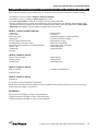
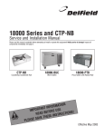
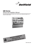
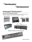
Nordic Zone™ Cold Food Bars
Service, Installation and Care Manual
Please read this manual completely before attempting to install or operate this equipment! Notify carrier of
damage! Inspect all components immediately. See page 2.
TION
A
M
R
O
T INF
N
A
T
R
O
USE
IMP
E
R
O
F
E
ONS!
I
T
EAD B
C
R
U
R
INST
N
E
S
CAUTIO
E
H
T
AVE
S
E
S
A
E
PL
August 2003
Nordic Zone Salad Bar Service and Installation Manual
CONTENTS
SERIAL NUMBER LOCATION
RECEIVING AND INSPECTING UNIT ................................................. 2
INSTALLATION.................................................................................. 3
ROUTINE MAINTENANCE ................................................................. 3
OPERATION ...................................................................................... 4
WIRING DIAGRAM............................................................................ 5
REPLACEMENT PARTS LIST............................................................. 5
FULL VIEW........................................................................................ 6
UNIT DETAILS................................................................................... 7
WALL MOUNT INSTALLATION.......................................................... 8
STANDARD WARRANTIES........................................................... 9-10
AUTHORIZED PARTS DEPOTS........................................................ 12
The serial number on Nordic Zone series is located behind the hinge
doors affixed to the interior stainless side. On the two section model,
it will be the two interior sides in the center of the assembly.
Always have the serial number of your unit available when calling for
parts or service. A complete list of authorized Delfield parts depots is
shown on the back cover of this manual.
Refrigeration system is set up as a R-404a refrigerant.
©2003 The Delfield Company. All rights reserved. Reproduction without written permission is prohibited. “Delfield” is a registered trademark of The Delfield Company.
Mechanical Data (dimensions for RT00012 (left side) and RT00013 (right side) combined
MODEL
NUMBER
LENGTH
PRODUCT
HOLDING AREA
#OF
DOORS
# OF
LIGHT BULBS
AMP
REMOTE
HP
REMOTE
BTU
SHIP WEIGHT
LBS.
NZ123
123.5” (313.69cm)
24” x 80.5” (60.69cm X 204.47cm)
4
(4) 48”
6
1.5
10,030
951
NZ207
207” (525.78cm)
24” x 124” (60.69 x 410 cm)
8
(8) 48”
(2) 6
(2) 1 1/2
20,060
1600
RECEIVING AND INSPECTING THE EQUIPMENT
Units are shipped blanket wrapped.
Care should be taken during unloading so the equipment is not
damaged while being moved into the building.
1.
2.
3.
2
Visually inspect the unit. Any damage should be noted and
reported to the delivering carrier immediately.
If damaged, open and inspect the unit with the carrier.
In the event that the unit is not damaged, yet upon opening,
there is concealed damage to the equipment notify the carrier.
Notification should be made verbally as well as in written
form.
4.
5.
6.
Request an inspection by the shipping company of the
damaged equipment. This should be done within 10 days
from receipt of the equipment.
Also open the mechanical compartment housing and visually
inspect the control package. Be sure lines are secure and
base is still intact.
Freight carriers can supply the necessary damage forms upon
request.
For customer service, call (800) 733-8829, (800) 773-8821, Fax (989) 773-3210, www.delfield.com
Nordic Zone Salad Bar Service and Installation Manual
INSTALLATION
In most instances, the salad bar units will arrive at the job site
uncrated, and caution must be taken not to damage any exterior
surfaces when moving into position. All internal components
including glass and mirrors will be shipped intact within the unit.
The area where the salad bar is to be located must be clean and the
floor level to assure a satisfactory installation.
In the appropriate location, units must be leveled with the finished
work height top of Corian® to be approximately 34” above finished
floor. Make sure units are level left to right as well as front to back.
The units are mounted on 6” high legs which can be adjusted up to 1”.
Corian® adhesive (supplied) is to be applied between Corian®
surfaces where they adjoin at center for proper moisture sealing.
Once the Corian® adhesive has been applied the units are ready to
be connected together where noted “spline here.” The locations are
directly behind the front nosing, below the upper front air diffuser,
and at the rear of the unit. Fasteners will be pre-installed within the
spline locations. Clean the units. Remove any excess silicone or
adhesive that may have squeezed out after splining units together.
With sufficient help (4-5) individuals, slowly push the connected units
“evenly” back to the wall at the rear. Make sure that all stubbed out
electrical, refrigeration lines, and plumbing lines clear the cabinet
structure. If not, make any necessary adjustments to clear these
components. Once the units are secure against the wall at the rear,
double check for level.
Locate and install Corian® rear and side splashes using adhesive
supplied. It may be necessary to trim pieces slightly to fit.
REFRIGERATION INSTALLATION
If the condensing units are to be set on the roof of the building, it
must be mounted on beams supplied by the roofing contractor or the
refrigeration contractor.
The condensing units must be a minimum of three feet apart to assure
proper air flow. Before the salad bar units arrive the refrigeration lines
must be installed from the condensing units down through the ceiling
and the rear wall and stubbed out per the drawing supplied to the
installer. The suction line should be 5/8 inch and the liquid line should
be 3/8 inch for most installations. The pipe insulation should be 1/2
inch wall thickness. A “p” trap must be installed at the lowest point
of the refrigeration lines. The electrical power supply must also be
stubbed through the rear wall.
The liquid line should be insulated if exposed to sunlight on roof
installations. All refrigeration lines must be secured to prevent
excessive vibrating or kinking of the copper tubing. Drain lines must
be installed to the drain stub on the bottom of the evaporator housing.
The drain must have proper slope to insure good drainage from the
evaporator pan. A minimum vacuum of 200 microns must be reached
before charging the units with R-404A refrigerant. The system must
be charged under a heat load with R-404A until the sight glass is clear.
Normal installations will require approximately 9lbs. of refrigerant for
each system.
All panels and covers must be installed in the proper locations and
the defrost timer must be set for the proper time. Defrost time for
normal installations should be 15 minutes every three hours and the
thermostat setting should be for 37º degrees box temperature.
NOTE: do not change setting of defrost timer or
thermostat. See page #4 for complete operation
instructions.
On/Off Switch located
behind the center
panel.
Thermostat located
behind the On/Off
switch panel.
For customer service, call (800) 733-8829, (800) 773-8821, Fax (989) 773-3210, www.delfield.com
3
Nordic Zone Salad Bar Service and Installation Manual
CLEANING INSTRUCTIONS
Daily cleaning of the interior and exterior of the unit is recommended.
All food must be removed from the interior before cleaning. Always
wear gloves and eye protection when handling cleaning solutions and
cleaning the salad bar.
GLASS: Use the mildest cleaning product available to clean glass
mirrors on the salad bar. Typically, soap and water, or ammonia will
clean the glass sufficiently. If stronger solutions are required, be
sure to use products designed for use on glass. Cleaning products
designed for other materials will leave residue that is not removable.
DISINFECTING: If the interior surface requires disinfecting, use a
product that contains Alkyl Ammonium Chloride to kill germs.
GREASE REMOVAL: Your regular daily cleaner may not remove
grease, fingerprints or other oily deposits found on glass. In this
case, use a stronger degreasing cleaner with butoxyethanol. Apply
this cleaner with sponge or cloth. Remove with a squeegee. Reclean
as necessary if streaks appear from degreaser.
DEGREASERS CAN HARM YOU. ALWAYS WEAR PROTECTIVE
GLOVES AND EYE PROTECTION WHEN USING THESE MATERIALS.
CLEANING REFRIGERATED PLATFORM: After removing all food
product and containers, lift the platform by grasping the front edge
and pulling up.
PLASTIC LAMINATE
In most cases, you only need to use a clean, damp nonabrasive
cotton cloth and a mild liquid detergent or household cleaner. Rinse
with clean water, using a clean, nonabrasive cotton cloth. Do not
flood the laminate, especially near seams since water can penetrate
and cause the substrate to swell. Dry the surface with a soft, clean,
non-abrasive cotton cloth.
DO NOT use abrasive cleaners, powders, steel wool, sandpaper,
or Scotch-Brite™ scouring pads. Use a trivet, insulated hot pad or
other protective device beneath all hot cookware, heat generating
appliances, or other heated objects.
CORIAN®
There are three types of countertop finishes: matte,
semigloss and gloss. All Corian® sinks and bowls
have the matte finish. Soapy water or ammonia-based
cleaners will remove most dirt and stains from all
types of finishes. However, slightly different techniques must be
used to remove difficult stains, depending on the finish.
Preventing Heat Damage: to prevent heat damage, always use a hot
pad or a trivet with rubber feet to protect your Corian.
When lifting front edge take caution to ensure palms are down as
to not pinch fingers. See Figure-1 and Figure-2.
The platform is mounted on two pistons, located at
each end of the platform. Once raised, clean food debris
from the area, paying attention not to force food down
CAUTION the drain of this area. This drain is easily clogged and
difficult to clean. Once food debris is cleaned out of the
area, use soap and water to wash the area and rinse. This will flow
down the drain. When cleaning is done, pull the platform down.
CABINET WOOD
To clean, gently wipe liquid spills up with a damp towel. If necessary
use with mild detergent.
Figure-1
4
Figure-2
For customer service, call (800) 733-8829, (800) 773-8821, Fax (989) 773-3210, www.delfield.com
Nordic Zone Salad Bar Service and Installation Manual
OPERATION
Start Up Procedures
1) Turn main power toggle switch to the ON position
2) Turn the toggle switch labeled lights to the ON position
3) Allow the case to reach refrigerator temperatures before filling
with product.
Shut Down Procedures
1) Turn the toggle switch labeled LIGHTS to the OFF position.
2) Turn the toggle switch labeled MAIN to the OFF position.
3) Remove product from the case and clean.
Display area must be in down position for fans to run.
COPIES OF THIS INFORMATION ARE ATTACHED TO THE INSIDE CENTER DOORS ON THE SALAD BAR.
TO INSURE THE PROPER OPERATION OF THIS AIR SCREEN SALAD BAR, PLEASE OBSERVE THE FOLLOWING.
The master back door light switch controls the power to the salad bar. When turned on, the process of circulating cold air and cooling down the
cold plates will start. This must be done one hour prior to stocking the salad bar with any food items. (At pre-determined times throughout the
day, the unit will cycle itself into a defrost mode.) Turn on the overhead display lights and you are ready to go.
Listed below are some important steps that must be followed
to insure that the air screen salad bar unit is set up correctly.
Do not install plastic wrap on any areas except the solid surface
portion of the cooling plates. Be careful not to block the return
air vents at the front or extreme ends of the cooling plates.
The mirrored panels along the rear of the unit must be securely
in place with no air leaks between mirror panels or at the outside
ends.
Control Knobs and Switches: All control and switches are
labeled accordingly.
1. Never attempt to change the setting of the defrost timer
or thermostat. Adjustments are to be made by qualified
service technicians only. Defrost cycles are factory preset and should not require field adjustments. In the event of a power loss to this unit,
timers will NOT need to be reset.
2. The toggle switch labeled lights are for the overhead display lights and can be operated as necessary. A master on/off switch is located in the
base area.
3. If the units are not keeping acceptable temperatures or performing properly an authorized service agent MUST BE contacted. Contact local
service company or Delfield Service direct at 800-733-8829.
4. When lifting front edge take caution to ensure palms are down as to not pinch fingers
- see photo to the right.
5. Cleaning under display area can be done by lifting front edge of display area - see photo above.
Consult service/maintenance manual for additional information.
Do not allow the pewter bowls or kale garnish to block the airflow from the louvered
areas at the inside back of the cooling plates. There must be a minimum of 3 inches
between the louvered panels and the pewter. Do not allow the pewter bowls or kale
garnish to block the return air vents at the front or extreme ends of the cooling plates.
PRIORITY:
All refrigerated Salad Bar items must
be at or below 40˚F prior to being
placed onto the salad bar. Do not stack
the salad bar with warm product.
For customer service, call (800) 733-8829, (800) 773-8821, Fax (989) 773-3210, www.delfield.com
5
6
GND
L1
NEUTRAL
BLACK
For customer service, call (800) 733-8829, (800) 773-8821, Fax (989) 773-3210, www.delfield.com
RED
FAN MOTOR
1
2
3 4
RED
5
WHITE
BLACK
WHITE
BLUE
STAINLESS STEEL ENCLOSURE
MAIN ON/OFF SWITCH
H1
HF
XF
H4
X1
H3
H1
X2
THERMOSTAT
H2
FUSE IKTK-R-5
FUSE IKTK-R-5
FUSE OFNM-15
RED
SOLENOID
BLACK
BLACK
RED
WHITE
RAIL FAN
BLACK
WHITE
RAIL FAN
RAIL FAN
RAIL FAN
(4) TO (8) FAN MOTORS
120v TO 24v TRANSFORMER
BLUE
BLUE
BLACK
LIGHT ON/OFF SWITCH
RAIL FAN
RAIL FAN
RAIL FAN
HEATING ELEMENTS
END LAMP
GREEN
RAIL FAN
BLACK
WHITE
BLACK
WHITE
GREEN
Y
Y
BALLAST, 120v INPUT, 227v OUTPUT
LAMP 2
LAMP 1
R
R
Y
Y
B
B
B
B
R
R
Nordic Zone Salad Bar Service and Installation Manual
WIRING DIAGRAM 207”
NOTE: each 1/2 section of the
salad bar requires separate electrical connections. This wiring
diagram represents a 1/2 section.
WHITE
GND
L1
NEUTRAL
RED
For customer service, call (800) 733-8829, (800) 773-8821, Fax (989) 773-3210, www.delfield.com
FAN MOTOR
1
2
3 4
RED
5
WHITE
BLACK
WHITE
BLUE
STAINLESS STEEL ENCLOSURE
MAIN ON/OFF SWITCH
H1
HF
XF
H4
X1
H3
H1
X2
THERMOSTAT
H2
FUSE IKTK-R-5
FUSE IKTK-R-5
FUSE OFNM-15
RED
SOLENOID
BLACK
BLACK
RED
WHITE
RAIL FAN
BLACK
WHITE
RAIL FAN
RAIL FAN
RAIL FAN
(4) TO (8) FAN MOTORS
120v TO 24v TRANSFORMER
BLUE
BLUE
BLACK
LIGHT ON/OFF SWITCH
RAIL FAN
RAIL FAN
RAIL FAN
HEATING ELEMENTS
END LAMP
GREEN
RAIL FAN
BLACK
WHITE
BLACK
WHITE
GREEN
Y
Y
BALLAST, 120v INPUT, 227v OUTPUT
LAMP 2
LAMP 1
R
R
Y
Y
B
B
B
B
R
R
Nordic Zone Salad Bar Service and Installation Manual
WIRING DIAGRAM 123” - NOTE: each 1/2 section of the salad bar requires separate electrical connections. This wiring diagram represents a 1/2 section.
WHITE
BLACK
7
Nordic Zone Salad Bar Service and Installation Manual
REPLACEMENT PARTS
LEFT and/or RIGHT HAND of 207” (each side)
Remote
ONE SIDE OF THE 123”
Remote
323457
2194620
RTP00013
RTP00034
RTP00012
3516222
5090025
6230110
RTP00040
3234645
RTP00024
RTP00022
2190154
3234242
2194345
3516151
RTP00009
RTP00044
3516172
3516173
2162691
323457
2194620
RTP00013
RTP00034
RTP00012
3516222
5090025
6230110
RTP00040
3234645
RTP00024
RTP00022
2190154
3234242
2194345
3516151
RTP00010
RTP00044
3516172
3516173
2162691
PART NUMBER
DESCRIPTION
Control knob ring guard
Fan safety switch
34” Fluorescent bulb
UCM-8 Fluorescent bulb
2-Bulb fluorescent bulb
Solenoid valve
Temperature control
Plastic insert
Alum hinge
6” leg
Limitron bussman fuse
Transformer
Rocker switch (lights, night power)
Plastic drain
Timer
Expansion valve
Evaporator coil
Mirror heater pad
Fan blade
Fan guard
Fan motor
HEATED MIRROR ASSEMBLY
PART NUMBER
DESCRIPTION
Control knob ring guard
Fan safety switch
34” Fluorescent bulb
UCM-8 Fluorescent bulb
2-Bulb fluorescent bulb
Solenoid valve
Temperature control
Plastic insert
Alum hinge
6” leg
Limitron bussman fuse
Transformer
Rocker switch (lights, night power)
Plastic drain
Timer
Expansion valve
Evaporator coil
Mirror heater pad
Fan blade
Fan guard
Fan motor
SILICONE ALL
EDGES AFTER
ASSEMBLY
AIRTECH FOAM INSULATION
INSTALL .75” ABS STRIP
HANGER IS HOLLOW
REMOVE BACKING
AND STICK TO
MIRROR BACK - 77
RTP00044
74 - RT00034
ASSEMBLE ONTO BACKER
75 - RTP00017
78 - RT000324
EDGE BAND SIDE
OF MIRRORS ONLY
76 - 3234037
8
For customer service, call (800) 733-8829, (800) 773-8821, Fax (989) 773-3210, www.delfield.com
Nordic Zone Salad Bar Service and Installation Manual
FULL VIEW 207”
Switch and defrost locations
For customer service, call (800) 733-8829, (800) 773-8821, Fax (989) 773-3210, www.delfield.com
9
Nordic Zone Salad Bar Service and Installation Manual
FULL VIEW 123”
20"
123.5"
83.5"
20"
135°
22"
32.3"
10.35"
102.8"
10
For customer service, call (800) 733-8829, (800) 773-8821, Fax (989) 773-3210, www.delfield.com
10.35"
Nordic Zone Salad Bar Service and Installation Manual
HOLE IN SIDE FOR SHARED
REFRIGERATION
LEG SCREW TOE PLATE TO UNIT
LEG RAIL
TOE PLATE BY OTHERS
6.12”
LEG RAIL
SCREW TO CLEAT IF USED
OPTIONAL 1” CLEAT FOR STRENGTH
TOE PLATE BY OTHERS
TOE PLATE INSTALLATION DETAIL
HOLE IN SHELF FOR
DRAIN/REF’G
ACCESS HOLE DETAIL
LAMINATE TOP
LAMINATE FRONT
TOP
18 SPLINE
1” CHROME HINGE
LAMINATE
FRONT
1” S/S SEAMS
BOLT SPLINERS
TOGETHER PRIOR TO
PUSHING AGAINST
WALL
REAR OF UPPER
STRUCTURE
LAMINATE END
CLEAR TEMPERED GLASS
SNEEZE GUARD
BASE
1/2” GLASS STOP
POWDER COATED ARM
REAR SPLINE DETAIL
GLASS SNEEZE GUARD DETAIL
SECTION VIEW
Sneeze shields to be “flip up” style and will be positioned to
meet NSF requirements (1/4” tempered glass)
NOTE: All return air chambers to be constructed of cleanable
approved materials.
For customer service, call (800) 733-8829, (800) 773-8821, Fax (989) 773-3210, www.delfield.com
11
Nordic Zone Salad Bar Service and Installation Manual
NSF Official Listing For Lighting System
12
For customer service, call (800) 733-8829, (800) 773-8821, Fax (989) 773-3210, www.delfield.com
Nordic Zone Salad Bar Service and Installation Manual
STANDARD LABOR GUIDELINES TO REPAIR OR REPLACE PARTS ON DELFIELD EQUIPMENT
Advice and recommendations given by Delfield Service Technicians do not constitute or guarantee any special coverage.
• A maximum of 1-hour is allowed to diagnose a defective component.
• A maximum of 1-hour is allowed for retrieval of parts not in stock.
• A maximum travel distance of 100 miles round trip and 2-hours will be reimbursed.
• Overtime, installation/start-up, normal control adjustments, general maintenance, glass breakage, freight damage, and/or
correcting and end-user installation error will not be reimbursed under warranty unless pre-approved with a Service Work
Authorization from Delfield. You must submit the number with the service claim.
LABOR OF 1-HOUR IS ALLOWED TO REPLACE:
• Thermostat
• Infinite Switch
• Door Jamb Switch
• Solenoid Coil
• Hi-limit/Thermal Protector Switch
• Fan Delay/Defrost Termination Switch
• Compressor Start Components and Overload Protector
• Defrost Timer
• Thermometer
• Gear Box
LABOR OF 2 HOURS TO REPLACE:
• Drawer Tracks/Cartridges
• Pressure Control
• Solenoid Valve
LABOR OF 3 HOURS TO REPLACE:
• EPR or CPR Valve
• Expansion Valve
•
•
•
•
•
•
•
•
•
Contactor/Relay
Transformer
Evaporator/Condenser Fan Motor and Blade
Circulating Fan Motor and Blade
Microprocessor Control
Water Level Sensor/Probe
Door Hinges, Locks, and Gaskets
Condensate Element
Springs/Lowerator
• Defrost Element
• Heating Element
• Locate/Repair Leak
• Condenser or Evaporator Coil
LABOR OF 4 HOURS TO REPLACE
• Compressor
This includes recovery of refrigerant and leak check.
$35.00 maximum reimbursement for refrigerant recovery (includes recovery machine, pump, torch, oil, flux, minor fittings,
solder, brazing rod, nitrogen, or similar fees.)
REFRIGERANTS
• R22 A maximum of $4.00/lb. or 25¢/oz. will be reimbursed.
• R134A A maximum of $5.00/lb. or 31¢/oz. will be reimbursed.
• R404A A maximum of $12.00/lb. or 75¢/oz. will be reimbursed.
For customer service, call (800) 733-8829, (800) 773-8821, Fax (989) 773-3210, www.delfield.com
13
Nordic Zone Salad Bar Service and Installation Manual
STANDARD ONE YEAR WARRANT (One year parts, 90 days labor.)
The Delfield Company (“Delfield”) warrants to the Original Purchaser
of the Delfield product (herein called the “Unit”) that such Unit, and all
parts thereof, will be free from defects in material and workmanship
under normal use and service for a period of one (1) year from
the date of shipment of the Unit to the Original Purchaser or, if the
Original Purchaser returns the warranty card completely filled out
including the date of installation within thirty (30) days of receipt
of the Unit, one (1) year from the date of installation. During this
one year warranty period, Delfield will repair or replace any defective
part or portion there of returned to Delfield by the Original Purchaser
which Delfield determines was defective due to faulty material or
workmanship. The Original purchaser will pay all labor, crating, freight
and related costs incurred in the removal of the Unit of defective
component and shipment to Delfield, except that during a period of
either ninety (90) days from the date of shipment of the Unit to the
Original Purchaser or, if the Original Purchaser returns the warranty
card completely filled out including the date of installation within thirty
(30) days of receipt of the Unit, ninety (90) days from the date of
installation Delfield will pay all related labor costs. Delfield will pay the
return costs if the Unit or part thereof was defective.
The term “Original Purchaser” as used herein means that person, firm,
association, or corporation for whom the Unit was originally installed.
This warranty does not apply to any Unit or part thereof that has
been subjected to misuse, neglect, alteration, or accident, such as
accidental damage to the exterior finish, operated contrary to the
recommendations specified by Delfield; or repaired or altered by anyone
other than Delfield in any way so as to, in Delfield’s sole judgement,
affect its quality or efficiency. This warranty does not apply to any Unit
that has been moved from the location where it was originally installed.
This warranty also does not cover the refrigerator drier or the light
bulbs used in the Unit. The warranty is subject to the user’s normal
maintenance and care responsibility as set forth in the Service and
Installation Manual, such as cleaning the condenser coil, and is in
lieu of all other obligations of Delfield. Delfield neither assumes, nor
authorizes any other person to assume for Delfield, any other liability
in connection with Delfield’s products.
Removal or defacement of the original Serial Number or Model Number
from any Unit shall be deemed to release Delfield from all obligations
hereunder or any other obligations, express or implied.
Parts furnished by suppliers to Delfield are guaranteed by Delfield only
to the extent of the original manufacturer’s express warranty to Delfield.
Failure of the Original Purchaser to receive such manufacturer’s express
warranty to Delfield. Failure of the Original Purchaser to receive such
manufacturers warranty shall in no way create any warranty, expressed
or implied, or any other obligation or liability on Delfield’s part in respect
thereof.
IF THE CUSTOMER IS USING A PART THAT RESULTS IN A VOIDED
WARRANTY AND A DELFIELD AUTHORIZED REPRESENTATIVE
TRAVELS TO THE INSTALLATION ADDRESS TO PERFORM WARRANTY
SERVICE, THE SERVICE REPRESENTATIVE WILL ADVISE CUSTOMER
THE WARRANTY IS VOID. SUCH SERVICE CALLS WILL BE BILLED
TO CUSTOMER AT THE AUTHORIZED SERVICE CENTER’S THEN
APPLICABLE TIME AND MATERIALS RATES. CONSIDER: CUSTOMER
MAY INITIATE A SERVICE AGREEMENT WITHOUT PARTS COVERAGE.
If shipment of a replacement part is requested prior to the arrival in
the Delfield factory of the part claimed to be defective, the Original
Purchaser must accept delivery of the replacement part of a C.O.D.
14
basis, with credit being issued after the part has been received and
inspected at Delfield’s plant and determined by Delfield to be within this
warranty.
Under no condition does this warranty give the Original Purchaser the
right to replace the defective Unit with a complete Unit of the same
manufacturer or of another make. Unless authorized by Delfield in
writing, this warranty does not permit the replacement of any part,
including the motor-compressor, to be made with the part of another
make or manufacturer.
No claims can be made under this warranty for spoilage of any products
for any reason, including system failure.
The installation contractor shall be responsible for building access,
entrance and field conditions to insure sufficient clearance to allow any
hood(s), vent(s), or Unit(s) if necessary, to be brought into the building.
Delfield will not be responsible for structural changes or damages
incurred during installation of the Unit or any exhaust system.
Delfield shall not be liable in any manner for any default or delay in
performance hereunder caused by or resulting from any contingency
beyond Delfield’s control, including, but not limited to, war,
governmental restrictions or restraints, strike, lockouts, injunctions,
fire, flood, acts of nature, short or reduced supply of raw materials, or
discontinuance of the parts by the original part manufacturer.
Except as provided in any Additional Four Year Protection Plan,
if applicable, and the Service Labor Contract, if applicable, the
foregoing is exclusive and in lieu of all other warranties, whether
written or oral, express or implied. This warranty supersedes
and excludes any prior oral or written representations or
warranties. Delfield expressly disclaims any implied warranties
of merchantability, fitness for a particular purpose of compliance
with any law, treaty, rule or regulation relating to the discharge of
substances into the environment. The sole and exclusive remedies
of any person relating to the Unit, and the full liability of Delfield for
any breach of this warranty, will be as provided in this warranty.
Other than this Delfield Standard One Year Limited Warranty, any
applicable Delfield Additional Four Year Protection Plan or applicable
Delfield Service Labor Contract, the Original Purchaser agrees and
acknowledges that no other warranties are offered or provided in
connection with or for the unit or any other part thereof.
In no event will Delfield be liable for special, incidental or consequential
damages, or for damages in the nature of penalties.
IF DURING THE WARRANTY PERIOD, CUSTOMER USES A PART FOR
THIS DELFIELD EQUIPMENT OTHER THAN AN UNMODIFIED NEW
OR RECYCLED PART PURCHASED DIRECTLY FROM DELFIELD OR
ANY OF ITS AUTHORIZED SERVICE CENTERS AND/OR THE PART
BEING USED IS MODIFIED FROM ITS ORIGINAL CONFIGURATION,
THIS WARRANTY WILL BE VOID. FURTHER, DELFIELD AND ITS
AFFILIATES WILL NOT BE LIABLE FOR ANY CLAIMS DAMAGES OR
EXPENSES INCURRED BY THE CUSTOMER WHICH ARISE DIRECTLY
OR INDIRECTLY, IN WHOLE OR IN PART, DUE TO THE INSTALLATION
OF ANY MODIFIED PART AND/OR PART RECEIVED FROM AN
UNAUTHORIZED SERVICE CENTER. If the warranty becomes void,
Customer may purchase from Delfield, if available, a Service
Agreement or service at the then current time and materials rate.
For more information on Delfield warranty’s log on and check out the
service section of our web site at www.delfield.com.
For customer service, call (800) 733-8829, (800) 773-8821, Fax (989) 773-3210, www.delfield.com
Nordic Zone Salad Bar Service and Installation Manual
ADDITIONAL FOUR YEAR PROTECTION PLAN
Delfield Model#
Serial #
Installation
Date
In addition to the Standard One Year Warranty on the MotorCompressor contained in the above listed Delfield product (the
“Unit”), The Delfield Company (“Delfield”) also agrees to repair, or
exchange with similar or interchangeable parts in design and capacity
at Delfield’s option, the defective Motor-Compressor contained in the
Unit (the “Motor-Compressor), or any part thereof, for the Original
Purchaser only, at any time during the four (4) years following the
initial one (1) year period commencing on the date of installation for
the Original Purchaser. Failure of the Original Purchaser to register
the registration card containing the Original Purchasers name,
address, date of installation, model number and serial number of
the Unit containing the Motor-Compressor within 30 days from the
date of installation shall void this warranty. This additional warranty
is only available if the Motor-Compressor is inoperative due to defects
in material or factory workmanship, as determined by Delfield in
its sole judgement and discretion. The Original Purchaser shall be
responsible for returning the defective Motor-Compressor to Delfield
prepaid, F.O.B. at the address shown on the back cover of this manual.
The term “Original Purchaser” as used herein means that person, firm,
association, or corporation for whom the Unit was originally installed.
The term “Motor-Compressor” as used herein does not include unit
base, air or water cooled condenser, receiver, electrical accessories
such as relay, capacitors, refrigerant controls, or condenser fan/motor
assembly. This warranty does not cover labor charges incidental to
the replacement of parts. This warranty further does not include
any equipment to which said condensing unit is connected, such as
cooling coils, temperature controls or refrigerant metering devices.
This warranty shall be void if the Motor-Compressor, in Delfield’s
sole judgement, has been subjected to misuse, neglect, alteration
or accident, operated contrary to the recommendations specified
by the Unit manufacturer, repaired or altered by anyone other than
Delfield in any way so as, in Delfield’s sole judgment, to affect its
quality or efficiency or if the serial number has been altered, defaced
or removed. This Warranty does not apply to a Motor-Compressor in
any Unit that has been moved from the location where it was originally
installed. The addition of methyl chloride to the condensing unit or
refrigeration system shall void this warranty.
(for Motor-Compressor only)
General Conditions
Delfield shall not be liable in any manner for any default or delay
in performance hereunder caused by or resulting from any
contingency beyond Delfield’s control, including, but not limited
to, war, governmental restrictions or restraints, strike, lockouts,
injunctions, fire, flood, acts of nature, short or reduced supply
of raw materials, or discontinuance of any part or the MotorCompressor by the unit manufacturer.
Replacement of a defective Motor-Compressor is limited to one (1)
Motor-Compressor by us during the four (4) year period. Delfield
shall replace the Motor-Compressor at no charge.
This warranty does not give the Original Purchaser of the MotorCompressor the right to purchase a complete replacement MotorCompressor of the same make or of another make. It further does
not permit the replacement to be made with a Motor-Compressor
of another kind unless authorized by Delfield. In the event Delfield
authorizes the Original Purchaser to purchase a replacement
Motor-Compressor locally, only the wholesale cost of the MotorCompressor is refundable.
Expressly excluded from this warranty are damages resulting from
spoilage of goods.
Except as provided in any applicable Standard One Year Limited
Warranty or applicable Service Labor Contract, the foregoing
is exclusive and in lieu of all other warranties, whether written
or oral, express or implied. This Warranty supersedes and
excludes any prior oral or written representations or warranties.
Delfield expressly disclaims any implied warranties of
merchantability, fitness for a particular purpose or compliance
with any law, treaty, rule or regulation relating to the MotorCompressor, and the full liability of Delfield for any breach of this
warranty, will be as provided in this warranty.
Other than any applicable Delfield Standard One year Limited
Warranty, this Delfield Additional Four Year Protection Plan and any
applicable Delfield Service Labor Contract, the Original Purchaser
agrees and acknowledges that no other warranties are offered or
provided in connection with or for the Motor-Compressor or any
part thereof.
In no event will Delfield be liable for special, incidental or
consequential damages, or for damages in the nature of penalties.
For customer service, call (800) 733-8829, (800) 773-8821, Fax (989) 773-3210, www.delfield.com
15
Nordic Zone Salad Bar Service and Installation Manual
NOTES:
16
For customer service, call (800) 733-8829, (800) 773-8821, Fax (989) 773-3210, www.delfield.com
AUTHORIZED PARTS DEPOTS
NORTH
AMERICA
12
10
4
4
8
5
1
11
6
2
3
14
13
7
9
12
1) The Delfield Company
980 South Isabella Road
Mt. Pleasant, MI 48858
800.733.8829
989.773.7981
989.773.3210 FAX
custom parts direct from Delfield
5) Contract Ice
2) A.I.S. Commercial Parts & Service
3) Appliance Installation Service
4) Pacific Coast Parts
1816 West 26th Street
Erie, PA 16508-1149
800.332.3732
814.456.3732
814.452.4843 FAX
1336 Main Street
Buffalo, NY 14209
800.722.1252
716.884.7425
716. 884.0410 FAX
serves: MD, NJ, OH, PA, VA, WV
serves: CT, DC, DE, MA, MD, ME,
15024 Staff Court
Gardena, CA 90248
1.800.531.1111
1.800.782.5747
Email: [email protected]
www.pacparts.com
NH, NJ, NY, PA, RI, VA, VT, WV
serves: AZ, CA, HI, NV, OR
6) E.M.C.O. Sales & Distributors
7) Stove Parts Supply/GCS Service
14450 Ewing Ave S. #100
Burnsville, MN 55306
800.422.2823
952.894.4427
952.894.2164 FAX
3909 St. Timothy Lane
St. Ann, MO 63074
800.972.7670
314.427.7477
314. 427.8190 FAX
2120 Solona St.
PO Box 14009
Fort Worth, TX 76117-0009
1.800.433.1804 toll free
1.800.272.7358 fax
serves: IA, MN, MT, ND, SD, WI
serves: AR, IA, IL, KS,
serves: AR, LA, NM, OK, TX
8) Garland Group
1177 Kamato Road
Mississauga, Ontario L4W1X4
800.427.6668
800.361.7745 FAX
serves: Canada
KY, MO, NE, OK, TX, NM, LA
9) Global Parts and Supplies
11) MicroDine, Inc.
10) Hawkins Commercial Appl. Serv.
2920 N.W. 109th Avenue
Miami, FL 33172
305 994.9994
305.994.9992 FAX
3000 S. Wyandot
Englewood, CO 80110
(800) 624-2117
(303) 7618861 FAX
International parts depot
serves: AZ, CO, KS, NE, NM, OK, UT, WY
44792 Helm
Plymouth, MI 48170
888.828.4454
734.451.2043
734.451.3215 FAX
serves: MI, IN, WI, OH
13) Southeastern Restaurant Services
2916 Sidco Drive
Nashville, TN 37204
615.726.0351
800.737.0351
615.259.4100 FAX
serves: FL, GA, MS, NC, SC, VA
serves: TN, AL
9923 S.W. 178th St.
Vashon, WA 98070
888.872.2465
206-463-1772
206.463.4431 FAX
serves: AK, HI, ID, MT, OR, WA
Delfield has 14 conveniently located Parts Depots to
ensure parts are handled promptly and accurately.
14) T.M.A.
2200 Norcross Parkway, Suite 210
Atlanta, GA 30071
800.235.6516
770.446.6177
770.446.3157 FAX
12) Performance Refrigeration Parts
Delfield reserves the right to update or make changes
to this list without prior notice
Please call 1-800-733-8829 or check the web at www.delfield.com
for a list of the current Parts Depots.
980 S. Isabella Rd., Mt. Pleasant, MI 48804-0470, U.S.A. • (989) 773-7981 or (800) 733-8821 • Fax (800) 669-0619 • www.delfield.com
Delfield reserves the right to make changes in design or specifications without prior notice. 2003 The Delfield Company. All rights reserved. Printed in the U.S.A.
DMNZ 06/03