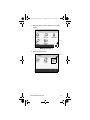
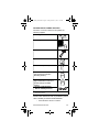
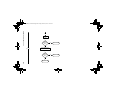
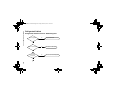
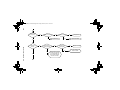
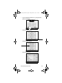
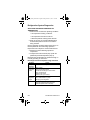
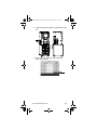
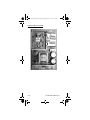
1
BIC_Model_Tech.book Page 1 Friday, March 15, 2013 7:01 PM Multiplex Blended Beverage System Technician’s Handbook This manual is updated as new information and models are released. Visit our website for the latest manual. www.manitowocfsg.com Leader in Ice & Beverage Dispensers Part Number STH034 3/13 BIC_Model_Tech.book Page 2 Friday, March 15, 2013 7:01 PM Safety Notices As you work on Manitowoc equipment, be sure to pay close attention to the safety notices in this handbook. Disregarding the notices may lead to serious injury and/or damage to the equipment. Throughout this handbook, you will see the following types of safety notices: ! Warning Text in a Warning box alerts you to a potential personal injury situation. Be sure to read the Warning statement before proceeding, and work carefully. ! Caution Text in a Caution box alerts you to a situation in which you could damage the equipment. Be sure to read the Caution statement before proceeding, and work carefully. BIC_Model_Tech.book Page 3 Friday, March 15, 2013 7:01 PM Procedural Notices As you work on Manitowoc equipment, be sure to read the procedural notices in this handbook. These notices supply helpful information which may assist you as you work. Throughout this handbook, you will see the following types of procedural notices: Important Text in an Important box provides you with information that may help you perform a procedure more efficiently. Disregarding this information will not cause damage or injury, but it may slow you down as you work. NOTE: Text set off as a Note provides you with simple, but useful, extra information about the procedure you are performing. BIC_Model_Tech.book Page 4 Friday, March 15, 2013 7:01 PM READ THESE BEFORE PROCEEDING: ! Caution Proper installation, care and maintenance are essential for maximum performance and troublefree operation of your equipment. Visit our website www.manitowocfsg.com for manual updates, translations, or contact information for service agents in your area. Important Routine adjustments and maintenance procedures outlined in this handbook are not covered by the warranty. ! Warning Read this manual thoroughly before operating, installing or performing maintenance on the equipment. Failure to follow instructions in this manual can cause property damage, injury or death. ! Warning Do not use electrical appliances or accessories other than those supplied by Manitowoc for your ice machine model. ! Warning Two or more people or a lifting device are required to lift this appliance. BIC_Model_Tech.book Page 5 Friday, March 15, 2013 7:01 PM ! Warning This equipment contains high voltage electricity and refrigerant charge. Installation and repairs are to be performed by properly trained technicians aware of the dangers of dealing with high voltage electricity and refrigerant under pressure.The technician must also be certified in proper refrigerant handling and servicing procedures. All lockout and tag out procedures must be followed when working on this equipment. ! Warning Do not damage the refrigeration circuit when installing, maintaining or servicing the unit. ! Warning Do not operate equipment that has been misused, abused, neglected, damaged, or altered/modified from that of original manufactured specifications. This appliance is not intended for use by persons (including children) with reduced physical, sensory or mental capabilities, or lack of experience and knowledge, unless they have been given supervision concerning use of the appliance by a person responsible for their safety. Do not allow children to play with this appliance. ! Warning All covers and access panels must be in place and properly secured, before operating this equipment. BIC_Model_Tech.book Page 6 Friday, March 15, 2013 7:01 PM ! Warning Do not obstruct machine vents or openings. ! Warning Do not store gasoline or other flammable vapors or liquids in the vicinity of this or any other appliance. ! Warning Do not clean with water jet. ! Warning It is the responsibility of the equipment owner to perform a Personal Protective Equipment Hazard Assessment to ensure adequate protection during maintenance procedures. BIC_Model_Tech.book Page 7 Friday, March 15, 2013 7:01 PM ! Warning When using electric appliances, basic precautions must always be followed, including the following: a. Read all the instructions before using the appliance. b. To reduce the risk of injury, close supervision is necessary when an appliance is used near children. c. Do not contact moving parts. d. Only use attachments recommended or sold by the manufacturer. e. Do not use outdoors. f. For a cord-connected appliance, the following must be included: • Do not unplug by pulling on cord. To unplug, grasp the plug, not the cord. • Unplug from outlet when not in use and before servicing or cleaning. • Do not operate any appliance with a damaged cord or plug, or after the appliance malfunctions or is dropped or damaged in any manner. Contact the nearest authorized service facility for examination, repair, or electrical or mechanical adjustment. g. Follow applicable lock out tag out procedures before working on equipment. h. Connect to a properly grounded outlet only. BIC_Model_Tech.book Page 8 Friday, March 15, 2013 7:01 PM This Page Intentionally Left Blank BIC_Model_Tech.book Page 9 Friday, March 15, 2013 7:01 PM Table of Contents Safety Notices . . . . . . . . . . . . . . . . . . . . . . 2 Procedural Notices . . . . . . . . . . . . . . . . . . 3 Read These Before Proceeding: . . . . . . . . .4 General Information About Blend-In-Cup . . . . . . . . . . . . . . . . . 15 Serial Number Location . . . . . . . . . . . . . . 15 Specifications . . . . . . . . . . . . . . . . . . . . . . 16 Dimensions . . . . . . . . . . . . . . . . . . . . . . . . .16 Product Delivery Location . . . . . . . . . . . . . .20 Electrical . . . . . . . . . . . . . . . . . . . . . . . . . . .22 Air / CO2, Plain & Chilled Water Inlets . . . .25 System Pressures . . . . . . . . . . . . . . . . . . . .26 Drain Connections . . . . . . . . . . . . . . . . . . . .27 Installation Step-by-Step Installation . . . . . . . . . . . . . 29 Pre-installation Checklist . . . . . . . . . . . . . . .29 Connections . . . . . . . . . . . . . . . . . . . . . . . .31 Checklist . . . . . . . . . . . . . . . . . . . . . . . . . . .33 Cleaning & Start-up . . . . . . . . . . . . . . . . . . .34 Demonstrate . . . . . . . . . . . . . . . . . . . . . . . .36 Post Installation Checklist . . . . . . . . . . . . . .37 Component Identification External . . . . . . . . . . . . . . . . . . . . . . . . . . . 39 Left Side & Front . . . . . . . . . . . . . . . . . . . . .39 Front . . . . . . . . . . . . . . . . . . . . . . . . . . . . . .39 Rear . . . . . . . . . . . . . . . . . . . . . . . . . . . . . . .40 Internal . . . . . . . . . . . . . . . . . . . . . . . . . . . 41 Top Rear . . . . . . . . . . . . . . . . . . . . . . . . . . .41 Top Left . . . . . . . . . . . . . . . . . . . . . . . . . . . .43 Top Right . . . . . . . . . . . . . . . . . . . . . . . . . . .44 Bottom Cabinet . . . . . . . . . . . . . . . . . . . . . .45 Maintenance General Maintenance . . . . . . . . . . . . . . . . 47 Daily, Weekly Monthly . . . . . . . . . . . . . . . . .47 Door Gasket Maintenance . . . . . . . . . . . . . .49 Drain Maintenance - Inside Lower Cabinet .50 Refrigerators . . . . . . . . . . . . . . . . . . . . . . . .50 Part Number STH034 3/13 9 BIC_Model_Tech.book Page 10 Friday, March 15, 2013 7:01 PM Stainless Steel Care & Cleaning . . . . . . . . .51 Doors/Hinges . . . . . . . . . . . . . . . . . . . . . . . .52 Preventing Blower Coil Corrosion . . . . . . . .53 Cleaning Kits . . . . . . . . . . . . . . . . . . . . . . . .53 Daily Cleaning - Zone 1 . . . . . . . . . . . . . . 54 Gather the following supplies . . . . . . . . . . .55 Blenders / Dispense Area Cleaning & Sanitizing 56 Weekly Cleaning - Zone 2 . . . . . . . . . . . . 67 Gather the following supplies . . . . . . . . . . .68 Product Line Cleaning & Sanitizing . . . . . . .69 Sanitizing Ice Bin & Water Nozzles (Optional) 77 Blenders / Dispense Area Cleaning & Sanitizing 83 Drain Cleaning (Optional) . . . . . . . . . . . . . .94 Monthly Cleaning - Zone 3 . . . . . . . . . . . 100 Gather the following supplies . . . . . . . . . . .100 Ice Maker / Bin Descaling, Cleaning & Sanitizing 102 Other Monthly Tasks . . . . . . . . . . . . . . . . . .113 Biannual Descaling- Zone 3 . . . . . . . . . . 115 Turn ON Descaling . . . . . . . . . . . . . . . . . . .116 Gather the following supplies . . . . . . . . . . .121 Ice Maker / Bin Descaling, Cleaning & Sanitizing 122 Turn OFF Descaling . . . . . . . . . . . . . . . . . .133 Product Line Flush . . . . . . . . . . . . . . . . . 137 Gather The Following Supplies . . . . . . . . . .138 Manual Ice Machine Cleaning . . . . . . . . . 150 For MB-8-1PP . . . . . . . . . . . . . . . . . . . . . . .150 Bin / Dispenser Descale, Clean, & Sanitize .154 Bin / Dispenser Disassembly Descale, Clean, & Sanitize . . . . . . . . . . . . . . . . . . . . . . . . . . . .156 Annual Planned Maintenance . . . . . . . . . 159 Operation Touch Screens . . . . . . . . . . . . . . . . . . . . . 161 Drink Selection Screen . . . . . . . . . . . . . . . .162 Flavor Selection Screen . . . . . . . . . . . . . . .163 Size Screen . . . . . . . . . . . . . . . . . . . . . . . . .164 Main Menu Screen . . . . . . . . . . . . . . . . . . .168 Manager’s Menu Screen . . . . . . . . . . . . . . .169 Product Inventory Screen . . . . . . . . . . . . . .200 Cleaning Screen . . . . . . . . . . . . . . . . . . . . .204 10 Part Number STH034 3/13 BIC_Model_Tech.book Page 11 Friday, March 15, 2013 7:01 PM Ice Making Sequence of Operation . . . . . 206 Ice Machines R290 Refrigerant . . . . . . . . . .206 Product Dispense Operation . . . . . . . . . . 207 Operation . . . . . . . . . . . . . . . . . . . . . . . . . . .207 Refrigerated Cabinet Operation . . . . . . . 208 Normal Operation . . . . . . . . . . . . . . . . . . . .208 Evaporator & Condenser Fan Motor Operation 209 Operation in the Clean/Sanitize cycle . . . . .210 Adaptive Defrost . . . . . . . . . . . . . . . . . . . . .210 High Temp Alarm . . . . . . . . . . . . . . . . . . . .210 Thermistor Failure . . . . . . . . . . . . . . . . . . . .210 Other Operations . . . . . . . . . . . . . . . . . . . 211 Recommended Cups . . . . . . . . . . . . . . . . . .211 Display Errors . . . . . . . . . . . . . . . . . . . . . . 213 Troubleshooting Control System . . . . . . . . . . . . . . . . . . . . . 219 Will Not Run Diagnostics . . . . . . . . . . . . . . .219 Beverage System . . . . . . . . . . . . . . . . . . . 221 Beverage System Diagnostics . . . . . . . . . .221 Procedure to Clear Blocked Line . . . . . . . . .222 Ice System . . . . . . . . . . . . . . . . . . . . . . . . . 224 Water System Checklist . . . . . . . . . . . . . . .225 ICE PRODUCTION & QUALITY CHECK . .226 MB-8-1PP Ice Machine Electrical Troubleshooting Flowchart . . . . . . . . . . . . . . . . . . . . . . . .228 Refrigerated Cabinet . . . . . . . . . . . . . . . . 235 Reach-in temperature Out of Range . . . . . .239 High Product Temperature . . . . . . . . . . . . .243 Refrigeration System Diagnostics . . . . . 244 Analyzing Discharge Pressure or Temperature 244 Analyzing Suction Pressure or Temperature 246 Analyzing Discharge Pressure or Temperature 248 Analyzing Suction Pressure or Temperature 250 Procedure to Clear Blocked Line . . . . . . 252 How to Check Air/CO2 Pressure . . . . . . . 255 How to Adjust Air/CO2 Pressure . . . . . . . . .259 How to Check Plain Water Pressure . . . . 263 Component Check Procedures Control System . . . . . . . . . . . . . . . . . . . . . 265 Part Number STH034 3/13 11 BIC_Model_Tech.book Page 12 Friday, March 15, 2013 7:01 PM ON/OFF Rocker Switch . . . . . . . . . . . . . . . .265 Power Relay . . . . . . . . . . . . . . . . . . . . . . . .267 Power Supply . . . . . . . . . . . . . . . . . . . . . . .269 UI (User Interface - Touchscreen) . . . . . . . .271 SRB Board . . . . . . . . . . . . . . . . . . . . . . . . . .275 Blender Control Board . . . . . . . . . . . . . . . . .279 CIP (Clean In Place) Relay Board . . . . . . . .282 Beverage Components . . . . . . . . . . . . . . 284 Pressure Regulator - Water or CO2 . . . . . .284 Water Dispense Solenoid Valve . . . . . . . . .285 Syrup Solenoid Valve . . . . . . . . . . . . . . . . .286 Non Drip Valve . . . . . . . . . . . . . . . . . . . . . .287 Product Pump . . . . . . . . . . . . . . . . . . . . . . .288 Step Motor . . . . . . . . . . . . . . . . . . . . . . . . . .289 Blender Motor . . . . . . . . . . . . . . . . . . . . . . .290 Home Position Switch . . . . . . . . . . . . . . . . .291 Door Switches . . . . . . . . . . . . . . . . . . . . . . .292 Water Rinse Solenoid Valve . . . . . . . . . . . .293 Ice Machine Components . . . . . . . . . . . . 294 High Pressure Cutout (HPCO) Control . . . .294 Ice Maker Bin Level Relay . . . . . . . . . . . . . .295 ICE CONDENSER COIL FAN . . . . . . . . . . .295 Infrared Ice Bin Control . . . . . . . . . . . . . . . .296 Refrigerated Cabinet . . . . . . . . . . . . . . . . 297 Temperature Thermistor - Nozzle, Cabinet or Defrost . . . . . . . . . . . . . . . . . . . . . . . . . . . . . . .297 Evaporator Fan Motor . . . . . . . . . . . . . . . . .299 Duct Fan Motor . . . . . . . . . . . . . . . . . . . . . .300 Condenser Fan Motor . . . . . . . . . . . . . . . . .300 Compressor Electrical Diagnostics . . . . . . .301 Compressor Drawing Locked Rotor . . . . . .302 Diagnosing Capacitors . . . . . . . . . . . . . . . .302 Filter-Driers . . . . . . . . . . . . . . . . . . . . . . . 303 Charts Total System Refrigerant Charge . . . . . . 305 Operational Charts . . . . . . . . . . . . . . . . . 306 R290 Refrigerant - Ice Machine . . . . . . . . . .306 Diagrams Wiring Diagrams . . . . . . . . . . . . . . . . . . . 307 R290 Ice Machine Refrigerant - Control System Wiring Diagram . . . . . . . . . . . . . . . . . . . . . .308 R290 Ice Machine Refrigerant - Refrigeration Cabinet Wiring Diagram . . . . . . . . . . . . . . .309 12 Part Number STH034 3/13 BIC_Model_Tech.book Page 13 Friday, March 15, 2013 7:01 PM Models: MB-8-1PP . . . . . . . . . . . . . . . . . . .309 R290 Ice Machine Refrigerant - Ice Maker & Ice Dispenser Wiring Diagram . . . . . . . . . . . . .310 Models: MB-8-1PP . . . . . . . . . . . . . . . . . . .310 R290 Ice Machine Refrigerant - Ice Maker Wiring Diagram . . . . . . . . . . . . . . . . . . . . . . . . . . . .311 Models: MB-8-1PP . . . . . . . . . . . . . . . . . . .311 R290 Ice Machine Refrigerant - CIP BOard Wiring Diagram . . . . . . . . . . . . . . . . . . . . . . . . . . . .312 Models: MB-8-1PP . . . . . . . . . . . . . . . . . . .312 . . . . . . . . . . . . . . . . . . . . . . . . . . . . . . . . . .313 . . . . . . . . . . . . . . . . . . . . . . . . . . . . . . . . . .314 Ice Machine Cleaning & Sanitizing Diagram 315 Models: MB-8-1PP . . . . . . . . . . . . . . . . . . .315 Ice Machine Cleaning & Sanitizing Diagram 316 Models: MB-8-1PP . . . . . . . . . . . . . . . . . . .316 Dispense System Diagram . . . . . . . . . . . . .317 Part Number STH034 3/13 13 BIC_Model_Tech.book Page 14 Friday, March 15, 2013 7:01 PM 14 Part Number STH034 3/13 BIC_Model_Tech.book Page 15 Friday, March 15, 2013 7:01 PM General Information About Blend-In-Cup The Blend-In-Cup beverage system is a self-contained dispensing unit that allows the operator to make flavor combinations of blended and non-blended drinks. It holds product flavoring in a refrigerated reach-in base enclosure, has a refrigerated ice making machine and includes one or two mixing modules. The operator controls and accesses the unit using a lighted touch screen. Icons on the drink selection screens represent the primary flavor combinations for the drinks. There are multiple drink size options. Menu changes and additions are uploaded using a USB mass storage device and the Menu Connect Software platform. On-screen instructions also include operator procedures for cleaning/sanitizing, checking inventory, replacing product bags, selecting drink sizes and manually preparing drinks. Managers and technicians have access to menu/software updates, diagnostics and other service screens. Serial Number Location The Blend-In-Cup beverage system serial number is listed on the serial number decal affixed to the middle of the lower back panel. Another serial number decal is located on the right side of the machine. Sample Serial Tag Part Number STH034 3/13 15 BIC_Model_Tech.book Page 16 Friday, March 15, 2013 7:01 PM Specifications DIMENSIONS ! Warning To avoid instability the installation area must be capable of supporting the weight of the equipment and a full bin of ice. Additionally the equipment must be level side to side and front to back. B A Elevation View 16 A 26.00" (66 cm) B 32.82" (83 cm) Part Number STH034 3/13 BIC_Model_Tech.book Page 17 Friday, March 15, 2013 7:01 PM C H D E F Elevation View C 71.19" (181 cm) F 26.00" (66 cm) D 65.19" (166 cm) H 75.07" (191 cm) E 60.25" (153 cm) Part Number STH034 3/13 17 BIC_Model_Tech.book Page 18 Friday, March 15, 2013 7:01 PM J I G Side View 18 G 32.82" (83 cm) I 36.15" (92 cm) J 39.09" (99 cm) Part Number STH034 3/13 – 310 lbs. (141 kg)/24 hr. Ice Maker Bin Storage 30 lbs (14 kg) Lower Cabinet MB-8-1PP Ice Capacity CAPACITY & WEIGHT 1/2 1/5 H.P. – 19.8 lbs. (9 kg) R-290 4.75 oz. (134.7 g) R-290 3.17 oz (90 g) Max Product Bin Load Refrigerant Charge 606 lbs (275 kg) Crated Shipping Weight 492 lbs ( 223 kg) Unpacked No Ice/ Product Empty Weight 656 lbs (298 kg) With Ice/ Product Full Weight BIC_Model_Tech.book Page 19 Friday, March 15, 2013 7:01 PM Part Number STH034 3/13 19 BIC_Model_Tech.book Page 20 Friday, March 15, 2013 7:01 PM PRODUCT DELIVERY LOCATION The location selected for the Blend-In-Cup Beverage System must meet the following criteria. • The air temperature must be at least 40°F (4°C), but must not exceed 90°F (32°C), climate class 4. • The location must not be near heat-generating equipment or in direct sunlight and must be protected from weather. • Plain or Chilled Inlet Water Temperature min/max = 40°F / 90°F (4°C / 32°C). • Always use the water supply line supplied when installing this appliance. Never reuse an old supply line. • Verify floor of install location is within 1/2” of level front to back, side to side. • Keep equipment area clear of combustible material. ! Warning Carbon Dioxide (CO2) displaces oxygen. Exposure to a high concentration of CO2 gas causes tremors, which are followed rapidly by loss of consciousness and suffocation. If a CO2 gas leak is suspected, particularly in a small area, immediately ventilate the area before repairing the leak. CO2 lines and pumps must not be installed in an enclosed space. An enclosed space can be a cooler or small room or closet. This may include convenience stores with glass door self serve coolers. If you suspect CO2 may build up in an area, venting of the B-I-B pumps and / or CO2 monitors must be utilized. 20 Part Number STH034 3/13 BIC_Model_Tech.book Page 21 Friday, March 15, 2013 7:01 PM Clearances Top 18" (46 cm) Sides 6" (15 cm) Back 6" (15 cm) Front 30" (76 cm) ! Warning Do not obstruct machine vents or openings. Heat of Rejection Model Heat of Rejection BTU/h All Single & Dual Spindle Base (Cabinet 1) 2100 Ice Maker (Cabinet 2) 5150 Operating Pressures PSIG Air Temperature Entering Condenser Coil Freeze Cycle Discharge Pressure Suction Pressure 70°F 150-170 17-23 90°F 180-200 18-24 110°F 225-245 21-27 Part Number STH034 3/13 21 BIC_Model_Tech.book Page 22 Friday, March 15, 2013 7:01 PM ELECTRICAL ! Warning All wiring must conform to local, state and national codes. Minimum Circuit Ampacity The minimum circuit ampacity is used to help select the wire size of the electrical supply. (Minimum circuit ampacity is not the Blend-In-Cup Beverage System’s running amp load.) The wire size (or gauge) is also dependent upon location, materials used, length of run, etc., so it must be determined by a qualified electrician. Electrical Requirements Refer to Blend-In-Cup Beverage System Model/Serial Plate for voltage/amperage specifications. ! Caution Operate equipment only on the type of electricity indicated on the specification plate. Voltage The standard voltage is 230VAC-50Hz. A dedicated electrical circuit is required, a power cord is provided with all units. Some models are available in different voltages and may be equipped with a different plug, for details on each model always refer to the serial number tag to verify electrical data. 22 Part Number STH034 3/13 BIC_Model_Tech.book Page 23 Friday, March 15, 2013 7:01 PM Minimum Circuit Amperage Chart Important Due to continuous improvements, this information is for reference only. Please refer to the serial number tag to verify electrical data. Serial tag information overrides information listed on this page. Model Numbers Voltage/Cycle/ Refrigerant MB-8-1PP Dual Spindle 230-240/50/1 R290 Total Breaker Size Amps (Max) 6.4 20A Grounding Instructions ! Warning The machine must be grounded in accordance with national and local electrical codes. This appliance must be grounded. In the event of malfunction or breakdown, grounding provides a path of least resistance for electric current to reduce the risk of electric shock. This appliance is equipped with a cord having an equipment-grounding conductor and a grounding plug. The plug must be plugged into an appropriate outlet that is properly installed and grounded in accordance with all local codes and ordinances. Bonding Instructions (230-240V 50 Hz Models Only) This appliance must be connected to the potential equalization system in accordance with EN60335-1 and EN60335-2-75. A bonding lug is provided on the lower right front corner of the appliance. ! Warning This machine must be connected to the potential equalization system. Part Number STH034 3/13 23 BIC_Model_Tech.book Page 24 Friday, March 15, 2013 7:01 PM ! Warning When using electric appliances, basic precautions must always be followed, including the following: a. Read all the instructions before using the appliance. b. To reduce the risk of injury, close supervision is necessary when an appliance is used near children. c. Do not contact moving parts. d. Only use attachments recommended or sold by the manufacturer. e. Do not use outdoors. f. For a cord-connected appliance, the following must be included: • Do not unplug by pulling on cord. To unplug, grasp the plug, not the cord. • Unplug from outlet when not in use and before servicing or cleaning. • Do not operate any appliance with a damaged cord or plug, or after the appliance malfunctions or is dropped or damaged in any manner. Contact the nearest authorized service facility for examination, repair, or electrical or mechanical adjustment. g. Follow applicable lock out tag out procedures before working on equipment. h. Always unplug before replacing the lamp. Replace the bulb with the same type. i. Connect to a properly grounded outlet only. See Grounding Instructions. 24 Part Number STH034 3/13 BIC_Model_Tech.book Page 25 Friday, March 15, 2013 7:01 PM AIR / CO2, PLAIN & CHILLED WATER INLETS Connections in the Rear of the Unit Chilled Water IN Air/ CO2 IN Plain Water IN Drain OUT ! Warning Connect to a potable water supply only. • • • • Use supplied 3/8” (.95 cm) panel-mounted hose barb and 6' (1.8 m) of beverage tubing to connect labeled coupling body fitting(s) on back of unit for each supply connection. Do not connect either water connection to a hot water supply. Be sure all hot water restrictors installed for other equipment are working. (Check valves on sink faucets, dishwashers, etc.) Install a water shut-off valve in the water line at the rear of the machine. Insulate water inlet lines to prevent condensation. Hard Water In areas where the water is highly concentrated with minerals the water should be tested by a water treatment specialist, and the recommendations of the specialist regarding filtration and/or treatment should be followed. Part Number STH034 3/13 25 BIC_Model_Tech.book Page 26 Friday, March 15, 2013 7:01 PM SYSTEM PRESSURES Plain & Chilled Water Important Requires the pressure measurement to be taken only when rinse water is spraying (flowing conditions) in a blender chamber. • • Plain Water Supply Pressure must be capable of continuously suppling a minimum of 35 psi (241 kPa, 2.41 bar) during flowing conditions. If a separate chilled water source is used the chilled supply pressure needs to be a minimum of 35 psi (241 kPa, 2.41 bar) at no flow conditions. Important Water pressure affects the blender area cleaning, a water booster may be required if pressure is too low. Air / CO2 Important Requires the pressure measurement to be taken only when a product pump is being activated (product pump during flow conditions). • • 26 Supply must be capable of 35 psi (241 kPa, 2.41 bar) minimum during flowing conditions, measured at the unit Air/CO2 regulator. See How to Check Air/CO2 Pressure on page 255. Supply to the unit not to exceed 80 psi (345 / 552 kPa, 3.45 / 5.52 bar) maximum during no flow conditions. Part Number STH034 3/13 BIC_Model_Tech.book Page 27 Friday, March 15, 2013 7:01 PM DRAIN CONNECTIONS • Connect supplied 1" ID hose to hose-barb connection on machine. • Drain lines must have a 1.5 inch drop per 5 feet of run (2.5 cm per meter), and must not create traps. • The floor drain must be large enough to accommodate drainage from all drains. • An air gap is included in the design of the machine for backflow prevention, plumb to local code. Part Number STH034 3/13 27 BIC_Model_Tech.book Page 28 Friday, March 15, 2013 7:01 PM This Page Intentionally Left Blank 28 Part Number STH034 3/13 BIC_Model_Tech.book Page 29 Friday, March 15, 2013 7:01 PM Installation Step-by-Step Installation These instructions are provided to assist the qualified installer. Contact your Manitowoc Foodservice Service Agent or call Manitowoc Foodservice for information regarding start-up services. Important Failure to follow these installation guidelines may affect warranty coverage. PRE-INSTALLATION CHECKLIST Keep product bags in a cooler at least 24 hours prior to installation. Any damage should be noted and reported to the delivering carrier immediately. Check the lower portion of the unit to be sure casters are not bent. Visually inspect the refrigeration package, compressor compartment housing. Be sure lines are secure and base is still intact. Inspect installation location behind the BIC for electrical outlet location, CO2, water hose fittings, and shutoff. Check voltage at outlet dedicated for BIC. Verify floor of install location is within 1/2” of level front to back, side to side and all casters are touching the floor. Part Number STH034 3/13 29 BIC_Model_Tech.book Page 30 Friday, March 15, 2013 7:01 PM ! Warning The mass of this appliance will allow it to move uncontrolled on an inclined surface. Adequate means must be provided to prevent uncontrolled movement at all times. Remove the side panels from the unit to make the board connections, Air/CO2 and Water Regulator gauges accessible. Check that board connections are secure and did not vibrate loose during shipment. Remove steel top panel. Check that the black chute cover is sitting securely on the chute. The ice maker will not operate properly if it is out of place. Check that both micro switches are in line with the motor above the blenders. 30 Part Number STH034 3/13 BIC_Model_Tech.book Page 31 Friday, March 15, 2013 7:01 PM CONNECTIONS Connections in the Rear of the Unit Chilled Water IN Air/ CO2 IN Plain Water IN Drain OUT Important Leave enough slack in the water/CO2/drain lines to allow access to the rear of the machine without disconnecting the lines. Water 1. Connect the Plain and Chilled (if used) water lines quick disconnect fittings and verify the water regulators are set to 35 psi (241 kPa, 2.41 bar). The Plain Water regulator is located on the left side of the unit and the Chilled Water regulator is located at the rear top. Final, during flow, settings will be made once the unit is in operation. See Cleaning & Start-up on page 34 and/or “How to Check Air/ CO2 Pressure” on page 255. Part Number STH034 3/13 31 BIC_Model_Tech.book Page 32 Friday, March 15, 2013 7:01 PM Air/CO2 2. Connect Air/CO2 line quick disconnect fitting. Verify the Air/CO2 regulator on the left side of the unit is set to 35 PSI (241 kPa, 2.41 bar). Final during flow settings will be made once the unit is in operation. Important Regulators are factory set but will need to be checked and possibly adjusted under flowing conditions once the unit is operational. 3. Confirm correct orientation of Water and Air/CO2 fittings. 4. Coil excess tubing and secure with tie straps. Drain 5. Route drain line (minimum 1" ID) to drain, maintain a 2" (51 mm) air gap. Cut to proper length if needed (do not leave loops in drain). See Drain Connections on page 27 Electrical 6. If all electrical and grounding requirements have been followed (See Electrical Requirements on page 22 & See Grounding Instructions on page 23) proceed to insert electrical plug from BIC into wall receptacle. 7. Turn power and compressor switches, on the left hand side of the unit and the rear, to the ON position. 8. The touch screen should energize and inform the user to perform Zone 2 & 3 cleaning before the unit can be put into operation. Important Do not add product to the machine until cleaning and sanitizing are complete. 32 Part Number STH034 3/13 BIC_Model_Tech.book Page 33 Friday, March 15, 2013 7:01 PM CHECKLIST Review before proceeding to Cleaning & Start-up. Has all of the internal packing been removed? Have all of the electrical, water and CO2 connections been made? Is there proper clearance around the machine for air circulation? Is the machine grounded / polarity correct? Has the machine been installed where the incoming water temperature will remain in the range of 40°F / 90°F (4°C / 32°C)? Have the regulators been set to 35 PSI (241 kPa, 2.41 bar)? Have the blender door sensor position(s) been checked? Have the Compressor and Power switches been turned to the ON position? Part Number STH034 3/13 33 BIC_Model_Tech.book Page 34 Friday, March 15, 2013 7:01 PM CLEANING & START-UP 9. Clean and sanitize the Blend-In-Cup machine by following the on screen instructions, See Weekly Cleaning - Zone 2 on page 67, “Monthly Cleaning Zone 3” on page 100, By doing so the following will have been completed; A. All beverage lines, ice maker, dispense area, and blender chambers, cleaned and sanitized. B. Water run through the drain to verify it is draining properly. C. Product bags retrieved from walk-in cooler, installed into the product bins and placed into their proper location in the cabinet. See Assigning Flavors on page 179 & “Procedure to Install a Product Bag” on page 202. D. All product lines primed and ready for use. NOTE: During the cleaning process is an ideal time to verify pressure regulator settings during flowing conditions. E. Verify the Plain Water regulator is set correctly during blend chamber cleaning, the regulator should maintain 35 psi (241 kPa, 2.41 bar) under flowing conditions. F. Verify the Air/CO2 regulator is set correctly during product line cleaning, the regulator should maintain 35 psi (241 kPa, 2.41 bar) under flowing conditions. NOTE: The Chilled Water Regulator needs to be a minimum of 35 psi (241 kPa, 2.41 bar) at no flow conditions. 34 Part Number STH034 3/13 BIC_Model_Tech.book Page 35 Friday, March 15, 2013 7:01 PM Label 10. Add labels to product bins, put labels in correct place. 11. Add labels anywhere else on the unit required. Software 12. Verify correct firmware is loaded. See Firmware Update Procedure on page 187. 13. Load recipes. See Recipe Loading Procedure on page 190. 14. Verify correct drinks and flavors are available. Calibrate Important Allow cabinet to reach operating temperature 36°F/2°C – 38°F/3°C before calibrating. Calibration will be inaccurate if performed above operating temperatures. 15. Product calibration can be performed once operating temperature has been reached. See Calibration Procedure on page 181 for step by step calibration instructions. Once completed the Blend-In-Cup machine is ready for use. 16. Reinstall top and side panels. 17. Push BIC into place. 18. Verify the unit is level and shim if necessary. Part Number STH034 3/13 35 BIC_Model_Tech.book Page 36 Friday, March 15, 2013 7:01 PM DEMONSTRATE 19. Using the Interface. See Touch Screens on page 161 20. How to make drink. See Procedure to Make a Drink on page 165. 21. Manager Menu options, using the default password “A”. (The password can be changed.) See Manager’s Menu Screen on page 169. 22. Set date and time to activate warranty. See Date & Time Setting on page 173 23. Complete start-up form, sign, and have store manager sign form. (Fax to number on form.) 36 Part Number STH034 3/13 BIC_Model_Tech.book Page 37 Friday, March 15, 2013 7:01 PM POST INSTALLATION CHECKLIST Has the machine been properly sanitized? Has each flavor been installed and primed? Have the Air/CO2 and Plain water regulators been correctly set during flowing conditions? Is the machine cycling ON/OFF on the temperature control? Has the owner/operator been instructed regarding maintenance procedures? Has the owner/operator completed the warranty registration card? Part Number STH034 3/13 37 BIC_Model_Tech.book Page 38 Friday, March 15, 2013 7:01 PM This Page Intentionally Left Blank 38 Part Number STH034 3/13 BIC_Model_Tech.book Page 39 Friday, March 15, 2013 7:01 PM Component Identification External LEFT SIDE & FRONT Cup Dispensers Plain Water & CO2 Regulator Gauges USB Port Touch Screen Blending Station Doors Power Switch Product Bins Pull Out Tray FRONT Blending Station Doors Product Dispense Area Whip Cream Door (Optional) Cabinet Door Part Number STH034 3/13 Syrup Rail & Dividers (Optional) 39 BIC_Model_Tech.book Page 40 Friday, March 15, 2013 7:01 PM REAR Chilled Water Gauge Compressor Switch Power Switch Water & Air/ CO2 Inlets Drain Power Cord 40 Part Number STH034 3/13 BIC_Model_Tech.book Page 41 Friday, March 15, 2013 7:01 PM Internal TOP REAR 2 1 3 4 5 6 7 8 1. 2. 3. 4. 5. 6. 7. 8. Chilled Water Regulator Chilled Water Solenoid Ice Maker Gear Box Ice Maker Control CIP Ice Maker Relay Ice Maker Evaporator Fan Ice Maker Compressor Ice Maker Evaporator Part Number STH034 3/13 41 BIC_Model_Tech.book Page 42 Friday, March 15, 2013 7:01 PM Ice Machine Control Box Start Cap Start Relay Circuit Control Board Switch, on/off, compressor POWER EARTH L1 L1 L2 L2 L2 L2 L2 RESET I.D. LABEL WATER PROBE DR C 20M 60M 2ND WTR B-T B-E SOFTWARE I.D. COMP. SWITCH LINE VAC COMM. 24 VAC COMP. FAN DRIVE Board, stand off control (4 required) Ice Machine Components Ice Making Unit Inlet Water Valve Reservoir Gear Motor Power Switch Control Switch Condenser Control Box Compressor 42 Part Number STH034 3/13 BIC_Model_Tech.book Page 43 Friday, March 15, 2013 7:01 PM TOP LEFT 3 1 4 12 5 6 2 7 8 18 9 10 11 19 14 15 13 17 16 1. 2. 3. 4. 5. 6. 7. 8. 9. 10. 11. 12. 13. 14. 15. 16. 17. 18. 19. CIP Board SRB 24 V Power Supply 4 Amp Fuse Power Supply 4 Amp Fuse CIP System Blender Home Position Micro Switch Blender Board Blender Motor Linear Slide Motor ON/OFF Switch USB Port Power Relay Blender Door Relay Blender 1 Rinse Nozzle Solenoid Water Dispense Solenoid Double Water inlet solenoid EMC Filter Air/C02 Regulator Water Regulator Part Number STH034 3/13 43 BIC_Model_Tech.book Page 44 Friday, March 15, 2013 7:01 PM TOP RIGHT 1 2 3 4 7 6 5 8 10 12 9 11 1. 2. 3. 4. 5. 6. 7. 8. 9. 10. 11. 12. 44 CIP Pump Dump valve Blender Motor Blender Home Position Micro Switch Mixer Board CIP Ice bin solenoid CIP C02/Air solenoid Ice Maker Bin Relay CIP Ice maker solenoid Linear Slide Motor Blender Door Relay Blender 2 rinse nozzle solenoid Part Number STH034 3/13 BIC_Model_Tech.book Page 45 Friday, March 15, 2013 7:01 PM BOTTOM CABINET Pumps & Solenoids 1 2 2 2 3 4 4 1. 2. 3. 4. None Drip Valves (x8) Product Pumps (x8) Product Bag Nozzles (x8) Solenoid Valves (x2) Part Number STH034 3/13 45 BIC_Model_Tech.book Page 46 Friday, March 15, 2013 7:01 PM Pump & Solenoid Numbering Expansion Valves 1 2 3 1 Product Pumps 4 2 5 6 5 3 7 8 6 7 1256 3478 4 Product Pumps 8 Air/CO2 Solenoids These numbers correspond to the product bins and inventory numbers in the User Interface. Refrigeration 1 3 3 2 4 1. 2. 3. 4. 46 Duct Fan Evaporator Coil Evaporator Fans (2) Cabinet Sensor Part Number STH034 3/13 BIC_Model_Tech.book Page 47 Friday, March 15, 2013 7:01 PM Maintenance General Maintenance This section covers common unit components and their care. The chart below is an overview of the maintenance that the end user and service technician should perform, and the frequency. These figures are the minimum required. If the Ice Machine is supplied with hard water, more frequent cleaning should be performed. If the condenser air filter is totally blocked, after one week, more frequent cleaning is recommended. (X = End User, S = Service Company DAILY, WEEKLY MONTHLY Maintenance Daily Blender / Dispense Area Cleaning/ Sanitizing (Zone 1 Cleaning) X Weekly Product Line Cleaning & Sanitizing (Zone 2 Cleaning) X Drain Cleaning X Monthly Clean Air Filters X Clean/Sanitize Ice Maker/Bin (Zone 3 Cleaning) X Descale Ice Maker/Bin (Zone 3 Cleaning) Clean Condenser Coil Inspect Ice Maker / Dispenser Parts Check Ice Quality Part Number STH034 3/13 X X 47 BIC_Model_Tech.book Page 48 Friday, March 15, 2013 7:01 PM QUARTERLY & BIANNUAL Maintenance 3 Months 6 Months Blender / Dispense Area Cleaning/ Sanitizing (Zone 1 Cleaning) Product Line Cleaning & Sanitizing (Zone 2 Cleaning) Drain Cleaning Clean Air Filters Clean/Sanitize Ice Maker/Bin (Zone 3 Cleaning) Descale Ice Maker/Bin (Zone 3 Cleaning) S Clean Condenser Coil X Inspect Ice Maker / Dispenser Parts Check Ice Quality ANNUAL, SHUTDOWN & START-UP After Prolonged Shutdown At Startup Product Line Cleaning & Sanitizing (Zone 2 Cleaning) X S Maintenance Annual Blender / Dispense Area Cleaning/ Sanitizing (Zone 1 Cleaning) Drain Cleaning X Clean Air Filters X Clean/Sanitize Ice Maker/Bin (Zone 3 Cleaning) X Descale Ice Maker/Bin (Zone 3 Cleaning) S Clean Condenser Coil 48 S X Inspect Ice Maker / Dispenser Parts S S S Check Ice Quality S S S Part Number STH034 3/13 BIC_Model_Tech.book Page 49 Friday, March 15, 2013 7:01 PM ! Warning Disconnect power to the unit before performing any service or maintenance functions. Important If the machine going to be shutdown for any length of time it is recommended to go through the Zone 2 - Weekly Cleaning both prior to turning off the unit and when returned to use. If the unit is turned off the product will no longer be kept cool in the refrigeration cabinet, remove all product bags and keep refrigerated to prevent spoilage. DOOR GASKET MAINTENANCE Door gaskets require regular cleaning to prevent mold and mildew buildup and also to retain the elasticity of the gasket. Gasket cleaning can be done with the use of warm soapy water. Avoid full strength cleaning products on gaskets as this can cause them to become brittle and crack. Never use sharp tools or knives to scrape or clean the gasket. Gaskets can be easily replaced and do not require the use of tools or an authorized service person. The gaskets are “Dart” style and can be pulled out of the groove in the door and new gaskets can be “pressed” back into place. Part Number STH034 3/13 49 BIC_Model_Tech.book Page 50 Friday, March 15, 2013 7:01 PM DRAIN MAINTENANCE - INSIDE LOWER CABINET Each unit has a drain located inside the unit that removes the condensation from the evaporator coil and routes it to an external condensate evaporator pan. Each drain can become loose or disconnected during normal use. If you notice water accumulation on the inside of the unit, be sure the drain tube is connected to the evaporator drain pan. If water is collecting underneath the unit, make sure the end of the drain tube is in the condensate evaporator in the machine compartment. The leveling of the unit is important as the units are designed to drain properly when level. Be sure all drain lines are free of obstructions. REFRIGERATORS ! Warning Do not damage the refrigeration circuit when installing, maintaining or servicing the unit. The interior and exterior can be cleaned using soap and warm water. If this isn’t sufficient, try ammonia and water or a nonabrasive liquid cleaner. When cleaning the exterior, always rub with the “grain” of the stainless steel to avoid marring the finish. Do not use an abrasive cleaner because it will scratch the stainless steel and can damage the breaker strips and gaskets. 50 Part Number STH034 3/13 BIC_Model_Tech.book Page 51 Friday, March 15, 2013 7:01 PM STAINLESS STEEL CARE & CLEANING To prevent discoloration or rust on stainless steel, several important steps need to be taken. First, we need to understand the properties of stainless steel. Stainless steel contains 70-80% iron, which will rust. It also contains 12-30% chromium, which forms an invisible passive film over the steel’s surface, which acts as a shield against corrosion. As long as the protective layer is intact, the metal is still stainless. If the film is broken or contaminated, outside elements can begin to break down the steel and begin to form discoloration or rust. Proper cleaning of stainless steel requires soft cloths or plastic scouring pads. Important Never Use Steel Pads, Wire Brushes or Scrapers! Cleaning solutions need to be alkaline based or nonchloride cleaners. Any cleaner containing chlorides will damage the protective film of the stainless steel. Chlorides are also commonly found in hard water, salts, and household and industrial cleaners. If cleaners containing chlorides are used, be sure to rinse repeatedly and dry thoroughly. Routine cleaning of stainless steel can be done with soap and water. Extreme stains or grease should be cleaned with a non-abrasive cleaner and plastic scrub pad. Always rub with the grain of the steel. There are stainless steel cleaners available which can restore and preserve the finish of the steel’s protective layer. Early signs of stainless steel breakdown are small pits and cracks. If this has begun, clean thoroughly and start to apply Part Number STH034 3/13 51 BIC_Model_Tech.book Page 52 Friday, March 15, 2013 7:01 PM stainless steel cleaners in attempt to restore the passivity of the steel. ! Caution Never use an acid based cleaning solution! Many food products have an acidic content, which can deteriorate the finish. Be sure to clean the stainless steel surfaces of ALL food products. Common items include: tomatoes, peppers and other vegetables. ! Caution Never use a high-pressure water wash for this cleaning procedure as water can damage the electrical components located near or at the condenser coil. DOORS/HINGES Over time and with heavy use doors and hinges may become loose. If this happens tighten the screws that mount the hinge brackets to the frame of the unit. Loose or sagging doors can cause the hinges to pull out of the frame, which may damage both the doors and the hinges. In some cases this may require trained & qualified service agents or maintenance personnel to perform repairs. NOTE: Do not place hot pans on/against the blue ABS liner. Do not throw items into the storage area. Failure to follow these recommendations could result in damage to the interior of the cabinet or to the blower coil. Overloading the storage area, restricting the airflow, and continuous opening and closing of the doors and drawers will hamper the unit’s ability to maintain operational temperature. 52 Part Number STH034 3/13 BIC_Model_Tech.book Page 53 Friday, March 15, 2013 7:01 PM PREVENTING BLOWER COIL CORROSION Immediately wipe up all spills. CLEANING KITS Complete cleaning kits are available for single spindle (part number 000-BIC-001R) and dual spindle (part number 000BIC-001Q) units. These kits include the following; • • • • • • (3) three 5 gallon buckets Bucket labels for Wash, Rinse, & Sanitizing Red & Blue cups for blender cleaning Squeeze Bottle Dispense Area Shield Tubing Manifold for product line cleaning Part Number STH034 3/13 53 BIC_Model_Tech.book Page 54 Friday, March 15, 2013 7:01 PM Daily Cleaning - Zone 1 NOTE: The following procedures are the basic daily cleaning instructions, on screen instructions can vary depending on the recipe that was created with the MenuConnect program. * These items are optional and may not be displayed on all EasyTouch screens during ZONE 1 Cleaning. • Time to complete - 15 minutes 1. Cycle touch screen to the Main Menu and select the Cleaning Icon. Main Menu Touch Screen 2. In the cleaning screen select the Zone 1 Icon. Cleaning Touch Screen 54 Part Number STH034 3/13 BIC_Model_Tech.book Page 55 Friday, March 15, 2013 7:01 PM GATHER THE FOLLOWING SUPPLIES Follow the on screen instructions and gather the following supplies; Clean towels (* Cloths) Spray Cleaner & Detergent Solution (Approved dish detergent solution) Spray Sanitizer & Solution (Approved sanitizer solution that provides 100 ppm available chlorine.) Red & Blue Cleaning Cups (1 of each per blender station) R B * Scoop, Cleaning Brush, Gloves & Safety Glasses * These items are optional and may not be displayed on all EasyTouch screens. NOTE: If other cleaners are used, it is possible they will not clean or sanitize your machine to NSF standards. • Press the down arrow to continue Part Number STH034 3/13 55 BIC_Model_Tech.book Page 56 Friday, March 15, 2013 7:01 PM BLENDERS / DISPENSE AREA CLEANING & SANITIZING Grate Removal / Blender Station Wash 1. Follow the on screen instructions; • * Put on gloves & safety glasses. 2. Remove grate from the mixer station(s) • Press the down arrow to continue Blend Chamber Grate Removal 3. Spray all surfaces inside blender station with cleaning solution. • * Then scrub thoroughly with approved cleaning brush. 4. Thoroughly wipe down all surfaces of mixer station & repeat for the other side if applicable. • 56 Press the down arrow to continue. Part Number STH034 3/13 BIC_Model_Tech.book Page 57 Friday, March 15, 2013 7:01 PM Dispensing Area Cleaning 1. Remove center grate from dispensing area. Dispense Area Screen 2. Spray all dispensing area surfaces with cleaning solution. • • * Then use approved cleaning brush to thoroughly scrub area. Press the down arrow to continue. 3. Thoroughly spray each individual dispense nozzle with cleaning solution and apply cleaner to each individual dispensing valve. • * Then use approved cleaning brush to carefully scrub area. 4. Thoroughly wipe all dispense valves and dispense area with a clean towel. • Press the down arrow to continue. Part Number STH034 3/13 57 BIC_Model_Tech.book Page 58 Friday, March 15, 2013 7:01 PM Mixer Door Removal 1. Slightly open mixer door. Mixer Door Removal Screen 2. Squeeze at bottom of door. 3. Tilt out and pull the door down and out. 4. Repeat for other door if applicable. • 58 Press the down arrow to continue. Part Number STH034 3/13 BIC_Model_Tech.book Page 59 Friday, March 15, 2013 7:01 PM Blender Station Wash 1. Completely spray blender station with cleaning solution. Blender Station Wash Screen • • * Use cleaning brush to thoroughly scrub down the entire area. * Using the approved cleaning brush, thoroughly scrub down top of blender cap and blender arm 2. Lift blender cap and thoroughly wipe down top of blade housing and bottom of blender cap. • • * Scrub (with the approved cleaning brush) top of blade housing and bottom of blender cap. Press the down arrow to continue. 3. Thoroughly spray with sanitizer solution. • * Using the approved cleaning brush to scrub entire blender assembly. 4. Repeat for other side if applicable. • Press the down arrow to continue. Part Number STH034 3/13 59 BIC_Model_Tech.book Page 60 Friday, March 15, 2013 7:01 PM Reinstall Grate(s)/Door(s) 1. Take all grate(s) and door(s) to sink to wash and sanitize. Grates & Doors Screen Important Never Use Steel Pads, Wire Brushes, Scrapers, or any Abrasive Cleaners / Scouring Pads! 2. Do not put in dishwasher or power soaker. 3. Reinstall mixer grate(s). 4. Reinstall dispensing area grate. 5. Reinstall mixer door(s) • 60 Press the down arrow to continue. Part Number STH034 3/13 BIC_Model_Tech.book Page 61 Friday, March 15, 2013 7:01 PM Blender Wash 1. Place blue cleaning cup(s) with wash solution in blender station(s) and close the blender doors. • Use approved dish detergent solution) Blender Wash Screen 2. Press the green check to begin. The blenders will lower into the wash solution and spin to clean. WASHING will display on the screen. Washing Screen Part Number STH034 3/13 61 BIC_Model_Tech.book Page 62 Friday, March 15, 2013 7:01 PM Follow the on screen instruction, when prompted remove the blue cup(s) and pour wash solution down the drain. Remove Cup Screen Close the blender door(s) and RINSING will display on the screen while the machine rinses the blenders. Rinse Cup Screen Finished will display on the screen then progress to the Blender Sanitizing screen. 62 Part Number STH034 3/13 BIC_Model_Tech.book Page 63 Friday, March 15, 2013 7:01 PM Blender Sanitizing 1. Place red sanitizing cup(s) with sanitizing solution in blender station(s) and close the blender doors. • Use approved sanitizer solution that provides 100 ppm available chlorine. Blender Sanitizing Screen 2. Press the green check to begin. The blenders will lower into the wash solution and spin to sanitize. SANITIZE will display on the screen. Washing Screen Part Number STH034 3/13 63 BIC_Model_Tech.book Page 64 Friday, March 15, 2013 7:01 PM Follow the on screen instruction, when prompted remove the red cup(s) and pour sanitizing solution down the drain. Remove Cup Screen Close the blender door(s) and RINSING will display on the screen while the machine rinses the blenders. Rinse Cup Screen Finished will display on the screen then progress to the Blender Station Sanitizing screen. 64 Part Number STH034 3/13 BIC_Model_Tech.book Page 65 Friday, March 15, 2013 7:01 PM Blender Station Sanitizing 1. Completely spray blender station with cleaning solution. • * Use cleaning brush to thoroughly scrub down the entire area. Blender Station Sanitizing Screen 2. Allow to air dry, Do not wipe off sanitizer! 3. Repeat for other side if applicable. • Press the down arrow to continue. Part Number STH034 3/13 65 BIC_Model_Tech.book Page 66 Friday, March 15, 2013 7:01 PM Dispensing Area Sanitizing 1. Thoroughly spray each individual dispense nozzle with sanitizer solution. Dispense Area Sanitizing Screen 2. Thoroughly spray dispense area with sanitizer solution. 3. Allow to air dry, Do not wipe off sanitizer! • • 66 * Remove gloves & safety glasses Press the green check to signify you have completed the Zone 1 Daily Cleaning. Part Number STH034 3/13 BIC_Model_Tech.book Page 67 Friday, March 15, 2013 7:01 PM Weekly Cleaning - Zone 2 NOTE: The following procedures are the basic weekly cleaning instructions, on screen instructions can vary depending on the recipe that was created with the MenuConnect program or options chosen in the Managers Menu. * These items are optional and may not be displayed on all EasyTouch screens during ZONE 2 Cleaning. • Time to complete - 1 hour 1. Cycle touch screen to the Main Menu and select the Cleaning Icon. Main Menu Touch Screen 2. In the cleaning screen select the Zone 2 Icon. Cleaning Touch Screen Part Number STH034 3/13 67 BIC_Model_Tech.book Page 68 Friday, March 15, 2013 7:01 PM NOTE: Failure to complete the weekly cleaning sequence entirely will not reset the weekly cleaning timer and will require the process to be repeated. GATHER THE FOLLOWING SUPPLIES Follow the on screen instructions and gather the following supplies; Clean towels (* Cloths) Spray Cleaner & Detergent Solution (Approved dish detergent solution) Spray Sanitizer & Solution (Approved sanitizer solution that provides 100 ppm available chlorine.) Red & Blue Cleaning Cups (1 of each per blender station) Set of Three (3) Cleaning Buckets (Wash, Rinse & Sanitize Solutions) R 1 B 2 3 Splash Shield Cleaning Manifold * Drain cleaner & Dispenser * Scoop, Cleaning Brush, Gloves & Safety Glasses * These items are optional and may not be displayed on all EasyTouch screens. 68 Part Number STH034 3/13 BIC_Model_Tech.book Page 69 Friday, March 15, 2013 7:01 PM NOTE: If other cleaners are used, it is possible they will not clean or sanitize your machine to NSF standards. • Press the down arrow to continue PRODUCT LINE CLEANING & SANITIZING Prepare Cleaning Solutions 1. Follow the on screen instructions; Prepare Solutions Screen • * Put on gloves & safety glasses. 2. Fill wash bucket with water and add detergent. (Approved dish detergent solution.) 3. Fill rinse bucket with water. 4. Fill sanitizer bucket with water and add approved sanitizer. (Approved sanitizer solution that provides 100 ppm available chlorine.) 5. Fill blue cleaning cup(s) with wash solution and set aside. (Approved dish detergent solution.) • Press the down arrow to continue. 6. Fill red sanitizing cup(s) with sanitizing solution and set aside. (Approved sanitizer solution that provides 100 ppm available chlorine.) • Press the down arrow to continue. Part Number STH034 3/13 69 BIC_Model_Tech.book Page 70 Friday, March 15, 2013 7:01 PM Washing Instructions 1. Remove grate from center dispensing area. Washing Instructions Screen 2. Install splash guard in dispense area. 3. Remove product holders from cabinet. 4. Take product holders to refrigerated storage. • Press the down arrow to continue 5. Spray and wipe each bib connector and area with cleaner. 6. Spray each bib connector and area with sanitizer. 7. Connect a cleaning hose to each product nozzle. • Press the down arrow to continue 8. Place cleaning manifold in wash bucket. 9. Press the green check to begin cleaning the lines. 70 Part Number STH034 3/13 BIC_Model_Tech.book Page 71 Friday, March 15, 2013 7:01 PM This will automatically send the wash solution through each line (slot), displaying the progress on the screen, 30 seconds per slot. Product Line Washing Screen When washing has completed the Rinsing Instructions Screen will appear automatically. Part Number STH034 3/13 71 BIC_Model_Tech.book Page 72 Friday, March 15, 2013 7:01 PM Rinsing Instructions 1. Remove cleaning manifold from wash bucket. Rinsing Instructions Screen 2. Place cleaning manifold in rinse bucket. 3. Press the green check begin rinsing the lines. This will automatically send the rinse solution through each line (slot), displaying the progress on the screen, 30 seconds per slot. Product Line Rinsing Screen When rinsing has completed the Sanitization Instructions Screen will appear automatically. 72 Part Number STH034 3/13 BIC_Model_Tech.book Page 73 Friday, March 15, 2013 7:01 PM Sanitization Instructions 1. Remove cleaning manifold from rinse bucket. Sanitizing Instructions Screen 2. Place cleaning manifold in sanitize bucket begin sanitizing the lines. 3. Press the green check begin sanitizing the lines. This will automatically send the sanitizing solution through each line (slot), displaying the progress on the screen, 30 seconds per slot. Product Line Sanitizing Screen When sanitizing has completed the Purging Instructions Screen will appear automatically. Part Number STH034 3/13 73 BIC_Model_Tech.book Page 74 Friday, March 15, 2013 7:01 PM Purging Instructions 1. Disconnect the cleaning hoses from the product nozzles. Sanitizing Instructions Screen 2. Press the green check begin purging the lines. Air is pushed through each line (slot) blowing out any remaining liquid, displaying the progress on the screen, 30 seconds per slot. Product Line Purging Screen When purging has completed the Reinstall Inventory Screen will appear automatically. 74 Part Number STH034 3/13 BIC_Model_Tech.book Page 75 Friday, March 15, 2013 7:01 PM Reinstall Inventory 1. Retrieve product holders from refrigerated storage. Reinstall Inventory Screen 2. Reinstall each product holder into correct slot. 3. Remove splash guard from dispense area. 4. Reinstall center grate under dispensing area. • Press the down arrow to continue. 5. Place a large cup under dispensing nozzles 6. Press the green check to prime each line. This will automatically prime each line with product. The screen will read Priming Slot X. Each slot will change from Purged to Clean. Product Line Purging Screen When priming has completed the Prime Completion Screen will appear automatically. Part Number STH034 3/13 75 BIC_Model_Tech.book Page 76 Friday, March 15, 2013 7:01 PM Auto Prime Complete 1. Remove and dispose of large cup with primed product. Prime Completed Screen 2. Press the green check to continue to the Sanitizing Ice Bin & Water Nozzles screen, if this feature is not turned on in the Managers Menu proceed to “Blenders / Dispense Area Cleaning & Sanitizing” on page 83. 76 Part Number STH034 3/13 BIC_Model_Tech.book Page 77 Friday, March 15, 2013 7:01 PM SANITIZING ICE BIN & WATER NOZZLES (OPTIONAL) * These steps will only display during the ZONE 2 Cleaning on units with this feature turned on in the Managers Menu. If this feature is not active the interface will automatically proceed to “Blenders / Dispense Area Cleaning & Sanitizing” on page 83. Gather the Following Supplies Cleaning Buckets - Set of Three (3) 1 2 3 Cleaning Hose * (Located below product bins) Ice Removal Chute Splash Guard Sanitizing Solution (Approved sanitizer solution that provides 100 ppm available chlorine.) * Scoop, Cleaning Brush, Gloves & Safety Glasses * These items are optional and may not be displayed on all EasyTouch screens. NOTE: If other cleaners are used, it is possible they will not clean or sanitize your machine to NSF standards. • Press the down arrow to continue Part Number STH034 3/13 77 BIC_Model_Tech.book Page 78 Friday, March 15, 2013 7:01 PM Removal of Ice Follow the on screen instructions; Ice Removal Screen 1. Install ice removal chute in dispenser area. 2. Place empty bucket on floor under ice chute. 3. Press the green check to begin dispensing ice. • The Ice Dispensing Timer Screen will display, the machine will empty of ice. Ice Dispense Timer Screen 78 Part Number STH034 3/13 BIC_Model_Tech.book Page 79 Friday, March 15, 2013 7:01 PM Ice Disposal 1. Dispose of ice in the bucket and set aside. Ice Disposal Screen 2. Remove ice removal chute from the dispenser area and set aside. 3. Press the green check. Part Number STH034 3/13 79 BIC_Model_Tech.book Page 80 Friday, March 15, 2013 7:01 PM Sanitizing Ice Bin & Water Nozzles Prep 1. Install splash guard in dispense area. Bin & Nozzles Prep Screen • * Put on gloves and safety glasses. 2. Fill sanitizer bucket with water and add sanitizer. (Use approved sanitizer solution that provides 100 ppm available chlorine.) 3. Place cleaning hose into the sanitizer bucket. 4. Press the green check to begin sanitizing the ice bin and water nozzles. • The Sanitizing Timer Screen will display, and count down during the sanitizing process. Sanitizing Timer Screen 80 Part Number STH034 3/13 BIC_Model_Tech.book Page 81 Friday, March 15, 2013 7:01 PM Discard Sanitizer 1. Install cleaning hose into the bottom of the refrigerated cabinet. Discard Sanitizer Screen 2. Discard remaining sanitizer from the bucket. 3. Press green check to continue. Part Number STH034 3/13 81 BIC_Model_Tech.book Page 82 Friday, March 15, 2013 7:01 PM Rinsing Sanitizer Prep 1. Install splash guard in the dispense area. Plain Water Rinse 2. Press the green check to begin the plain water rinse cycle. Rinse Timer Screen • 82 The Rinse Timer Screen will display, and count down during the rinsing process then automatically proceed to the Grate Removal/ Blender Station Wash Screen. Part Number STH034 3/13 BIC_Model_Tech.book Page 83 Friday, March 15, 2013 7:01 PM BLENDERS / DISPENSE AREA CLEANING & SANITIZING Grate Removal / Blender Station Wash 1. Remove grate from the mixer station(s) Blend Chamber Grate Removal 2. Spray all surfaces inside blender station with cleaning solution. • • * Then scrub thoroughly with approved cleaning brush. Press the down arrow to continue. 3. Thoroughly wipe down all surfaces of mixer station & repeat for the other side if applicable. • Press the down arrow to continue. Part Number STH034 3/13 83 BIC_Model_Tech.book Page 84 Friday, March 15, 2013 7:01 PM Dispensing Area Cleaning 1. Remove center grate from dispensing area. Dispense Area Screen 2. Spray all dispensing area surfaces with cleaning solution. • • * Then use approved cleaning brush to thoroughly scrub area. Press the down arrow to continue. 3. Thoroughly spray each individual dispense nozzle with cleaning solution and apply cleaner to each individual dispensing valve. • * Then use approved cleaning brush to carefully scrub area. 4. Thoroughly wipe all dispense valves and dispense area with a clean towel. • 84 Press the down arrow to continue. Part Number STH034 3/13 BIC_Model_Tech.book Page 85 Friday, March 15, 2013 7:01 PM Mixer Door Removal 1. Slightly open mixer door. Mixer Door Removal Screen 2. Squeeze at bottom of door. 3. Tilt out and pull the door down and out. 4. Repeat for other door if applicable. • Press the down arrow to continue. Part Number STH034 3/13 85 BIC_Model_Tech.book Page 86 Friday, March 15, 2013 7:01 PM Blender Station Wash 1. Completely spray blender station with cleaning solution. Blender Station Wash Screen • • * Use cleaning brush to thoroughly scrub down the entire area. * Using the approved cleaning brush, thoroughly scrub down top of blender cap and blender arm. 2. Lift blender cap and thoroughly wipe down top of blade housing and bottom of blender cap. • • * Scrub (with the approved cleaning brush) top of blade housing and bottom of blender cap. Press the down arrow to continue. 3. Thoroughly spray with sanitizer solution. • * Using the approved cleaning brush to scrub entire blender assembly. 4. Repeat for other side if applicable. • 86 Press the down arrow to continue. Part Number STH034 3/13 BIC_Model_Tech.book Page 87 Friday, March 15, 2013 7:01 PM Reinstall Grate(s)/Door(s) 1. Take all grate(s) and door(s) to sink to wash and sanitize. Grates & Doors Screen Important Never Use Steel Pads, Wire Brushes, Scrapers, or any Abrasive Cleaners / Scouring Pads! 2. Do not put in dishwasher or power soaker. 3. Reinstall mixer grate(s). 4. Reinstall dispensing area grate. 5. Reinstall mixer door(s). • Press the down arrow to continue. Part Number STH034 3/13 87 BIC_Model_Tech.book Page 88 Friday, March 15, 2013 7:01 PM Blender Wash 1. Place blue cleaning cup(s) with wash solution in blender station(s) and close the blender doors. • 0.425 oz/5 gal or Approved dish detergent solution) Blender Wash Screen 2. Press the green check to begin. The blenders will lower into the wash solution and spin to clean. WASHING will display on the screen. Washing Screen 88 Part Number STH034 3/13 BIC_Model_Tech.book Page 89 Friday, March 15, 2013 7:01 PM Follow the on screen instruction, when prompted remove the blue cup(s) and pour wash solution down the drain. Remove Cup Screen Close the blender door(s) and RINSING will display on the screen while the machine rinses the blenders. Rinse Screen Finished will display on the screen then progress to the Blender Sanitizing screen. Part Number STH034 3/13 89 BIC_Model_Tech.book Page 90 Friday, March 15, 2013 7:01 PM Blender Sanitizing 1. Place red sanitizing cup(s) with sanitizing solution in blender station(s) and close the blender doors. • Use approved sanitizer solution that provides 100 ppm available chlorine. Blender Sanitizing Screen 2. Press the green check to begin. The blenders will lower into the wash solution and spin to sanitize. SANITIZE will display on the screen. Sanitizing Screen 90 Part Number STH034 3/13 BIC_Model_Tech.book Page 91 Friday, March 15, 2013 7:01 PM Follow the on screen instruction, when prompted remove the red cup(s) and pour sanitizing solution down the drain. Remove Cup Screen Close the blender door(s) and RINSING will display on the screen while the machine rinses the blenders. Rinse Screen Finished will display on the screen then progress to the Blender Station Sanitizing screen. Part Number STH034 3/13 91 BIC_Model_Tech.book Page 92 Friday, March 15, 2013 7:01 PM Blender Station Sanitizing 1. Completely spray blender station with cleaning solution. • * Use cleaning brush to thoroughly scrub down the entire area. Blender Station Sanitizing Screen 2. Allow to air dry, Do not wipe off sanitizer! 3. Repeat for other side if applicable. • 92 Press the down arrow to continue. Part Number STH034 3/13 BIC_Model_Tech.book Page 93 Friday, March 15, 2013 7:01 PM Dispensing Area Sanitizing 1. Thoroughly spray each individual dispense nozzle with sanitizer solution. Dispense Area Sanitizing Screen 2. Thoroughly spray dispense area with sanitizer solution. 3. Allow to air dry, Do not wipe off sanitizer! • Press the green check to signify you have completed the Zone 2 Weekly Cleaning or continue on to Drain Cleaning if equipped with this option. Part Number STH034 3/13 93 BIC_Model_Tech.book Page 94 Friday, March 15, 2013 7:01 PM DRAIN CLEANING (OPTIONAL) * Only for units with this feature. These steps will only display during the ZONE 2 Cleaning on units with this feature turned on in the loaded recipe file. If this feature is not active the interface will automatically proceed to “Weekly Cleaning Completed” on page 99 Prepare Unit for Drain Cleaning 1. Remove doors from blender station(s). Drain Cleaning Screen 1 2. Remove grate from center dispensing area. 3. Remove grate from blender station(s). • Press the down arrow to continue. 4. Slowly pour 1 gal / 3.8 L of hot (120-130°F / 49-54°C) water into each drain. • 94 Press the down arrow to continue. Part Number STH034 3/13 BIC_Model_Tech.book Page 95 Friday, March 15, 2013 7:01 PM Prepare Drain Cleaning Solution 1. On the top of the dispenser, open pressure relief knob by turning counter-clockwise. Prepare Cleaning Solution 2. Remove the cap rom the dispenser. • Press the down arrow to continue. 3. Pour 1 gal / 3.8 L of hot (120-130°F / 49-54°C) water into the dispenser. • Press the down arrow to continue. 4. Quickly pour one packet of drain cleaner into dispenser. Mix Cleaning Solution 5. Immediately replace and tighten cap. 6. On the top of the dispenser, close pressure relief knob by turning clockwise. • Press the down arrow to continue. Part Number STH034 3/13 95 BIC_Model_Tech.book Page 96 Friday, March 15, 2013 7:01 PM 7. Shake dispenser to dissolve cleaner. • Press the down arrow to continue. Drain Cleaning 1. Carefully purge a small amount of solution from the dispenser into the sink. Purge Drain Cleaning Dispenser 2. This helps prevent “sputtering” of solution and possible splash onto clothing or eyes. • Press the down arrow to continue. 3. Carefully spray an equal amount of the solution into each drain. • 96 Press the down arrow to continue. Part Number STH034 3/13 BIC_Model_Tech.book Page 97 Friday, March 15, 2013 7:01 PM Post Drain Cleaning 1. Open the pressure relief knob again by turning counter-clockwise. Post Drain Cleaning Screen 2. Remove cap from the dispenser. 3. Rinse the dispenser with warm (75-90°F/23-32°C) water and return to the proper storage area. • Press the down arrow to continue. Part Number STH034 3/13 97 BIC_Model_Tech.book Page 98 Friday, March 15, 2013 7:01 PM Reinstall Grate(s) / Door(s) 1. Wipe drain areas and work surface with sanitized towel to remove drain cleaner. Grates & Doors Install Screen 2. Reinstall mixer grate(s). 3. Reinstall dispensing area grate. 4. Reinstall mixer door(s). • Press the down arrow to continue. Important Drain cleaner is most effective when left for four (4) hours, but the machine can be used as needed. • 98 Press the green check to continue. Part Number STH034 3/13 BIC_Model_Tech.book Page 99 Friday, March 15, 2013 7:01 PM Weekly Cleaning Completed 1. * Remove gloves & safety glasses. Completed Screen 2. Weekly cleaning has been completed. 3. Unit will need to be cleaned again in 7 days. 4. Return supplies to cleaning kit. 5. Press the green check to signify you have completed the Zone 2 Weekly Cleaning. The screen will return to the Main Menu Screen. Part Number STH034 3/13 99 BIC_Model_Tech.book Page 100 Friday, March 15, 2013 7:01 PM Monthly Cleaning - Zone 3 NOTE: All steps will be displayed on screen. * These items are optional and may not be displayed on all EasyTouch screens during ZONE 3 Cleaning. • Time to complete - 1 hour 45 minutes 1. Cycle touch screen to the Main Menu and select the Cleaning Icon. Main Menu Touch Screen 2. In the cleaning screen select the Zone 3 Icon. Cleaning Touch Screen NOTE: Failure to complete the Zone 3 cleaning sequence in it’s entirety could affect drink quality and will not reset the monthly cleaning timer which will require the process to be repeated. GATHER THE FOLLOWING SUPPLIES 100 Part Number STH034 3/13 BIC_Model_Tech.book Page 101 Friday, March 15, 2013 7:01 PM Follow the on screen instructions and gather the following supplies; Cleaning Buckets - Set of 2 1 2 Cleaning Hose Ice Removal Chute Splash Guard Clean towels (* Cloths) Sanitizing Solution (Approved sanitizer solution that provides 100 ppm available chlorine.) * Scoop, Cleaning Brush, Gloves & Safety Glasses * These items are optional and may not be displayed on all EasyTouch screens. NOTE: If other cleaners are used, it is possible they will not clean or sanitize your machine to NSF standards. • Press the down arrow to continue Part Number STH034 3/13 101 BIC_Model_Tech.book Page 102 Friday, March 15, 2013 7:01 PM ICE MAKER / BIN DESCALING, CLEANING & SANITIZING Removal of Ice Follow the on screen instructions; Ice Removal Screen 1. Install ice removal chute in dispenser area. 2. Place empty bucket on floor under ice chute. 3. Press the green check to begin dispensing ice. • The Ice Dispensing Timer Screen will display, the machine will empty of ice. Ice Dispense Timer Screen 102 Part Number STH034 3/13 BIC_Model_Tech.book Page 103 Friday, March 15, 2013 7:01 PM Ice Disposal 1. Dispose of ice in the bucket and set aside. Ice Disposal Screen 2. Remove ice removal chute from the dispenser area and set aside. 3. Press the green check to continue. Part Number STH034 3/13 103 BIC_Model_Tech.book Page 104 Friday, March 15, 2013 7:01 PM Sanitizing Ice Maker Prep 1. Install splash guard in the dispense area. Sanitizing Prep Screen • * Put on gloves and safety glasses. 2. Fill sanitizer bucket with water and add sanitizer. (Use approved sanitizer solution that provides 100 ppm available chlorine.) 3. Place cleaning hose into the sanitizer bucket. 4. Press the green check to begin sanitizing the ice machine. • The Sanitize Ice Maker Timer Screen will display and count down during the sanitizing process. • Discard Sanitizer & Ice Prep Screen will display once completed. Sanitizing Timer Screen 104 Part Number STH034 3/13 BIC_Model_Tech.book Page 105 Friday, March 15, 2013 7:01 PM Discard Sanitizer & Ice Purge Prep 1. Discard remaining sanitizer from the bucket. Discard Sanitizer Screen 2. Removal of Ice. 3. Install ice removal chute in dispenser area. 4. Place empty bucket on the floor under the ice chute. ! Warning This ice production will contain residual cleaning chemicals and must be discarded. 5. \Press the green check to begin dispensing ice. • The Ice Dispensing Timer Screen will display, the machine will empty of ice. Ice Dispense Timer Screen Part Number STH034 3/13 105 BIC_Model_Tech.book Page 106 Friday, March 15, 2013 7:01 PM Ice Disposal 1. Dispose of ice in the bucket and set aside. Ice Disposal Screen 2. Remove ice removal chute from the dispenser area and set aside. 3. Press the green check to continue. 106 Part Number STH034 3/13 BIC_Model_Tech.book Page 107 Friday, March 15, 2013 7:01 PM Sanitizing Ice Bin & Water Nozzles Prep 1. Install splash guard in dispense area. Bin & Nozzles Prep Screen • * Put on gloves and safety glasses. 2. Fill sanitizer bucket with water and add sanitizer. (Use approved sanitizer solution that provides 100 ppm available chlorine.) 3. Place cleaning hose into the sanitizer bucket. 4. Press the green check to begin sanitizing the ice bin and water nozzles. • The Sanitizing Timer Screen will display, and count down during the sanitizing process. Sanitizing Timer Screen Part Number STH034 3/13 107 BIC_Model_Tech.book Page 108 Friday, March 15, 2013 7:01 PM Discard Sanitizer 1. Install cleaning hose into the bottom of the refrigerated cabinet. Discard Sanitizer Screen 2. Discard remaining sanitizer from the bucket. 3. Press green check to continue. 108 Part Number STH034 3/13 BIC_Model_Tech.book Page 109 Friday, March 15, 2013 7:01 PM Rinsing Sanitizer Prep 1. Install splash guard in the dispense area. Plain Water Rinse 2. Press the green check to begin the plain water rinse cycle. • The Rinse Timer Screen will display, and count down during the rinsing process then automatically proceed to the Cleaning Solution Ice Production Screen. Rinse Timer Screen Part Number STH034 3/13 109 BIC_Model_Tech.book Page 110 Friday, March 15, 2013 7:01 PM Ice Maker Cleaning Solution Ice • Ice will then be produced using water from the unit’s chilled water source to remove any remaining cleaning solution from the ice maker. Ice Production Timer Screen ! Warning This ice production will contain residual cleaning chemicals and must be discarded. 110 Part Number STH034 3/13 BIC_Model_Tech.book Page 111 Friday, March 15, 2013 7:01 PM Removal of Ice 1. Install ice removal chute in dispenser area. Ice Removal Screen 2. Place empty bucket on floor under ice chute. 3. Press the green check to begin dispensing ice. • The Ice Dispensing Timer Screen will display, the machine will empty of ice. Part Number STH034 3/13 111 BIC_Model_Tech.book Page 112 Friday, March 15, 2013 7:01 PM Ice Disposal 1. Dispose of ice in the bucket and set aside. Ice Disposal Screen 2. Remove ice removal chute from the dispenser area and set aside. 3. Press the green check to signify you have completed the Zone 3 Monthly Cleaning. The screen will return to the Main Menu Screen. Important Ice storage has been depleted, low ice level may exist for 30 minutes! 112 Part Number STH034 3/13 BIC_Model_Tech.book Page 113 Friday, March 15, 2013 7:01 PM OTHER MONTHLY TASKS Air Filters For units equipped with upper and/or lower air filters. Each month check the air filters to be sure they are clean and allow proper airflow. Air Filter Locations First access the rear of the unit. Slide them out one at a time and inspect them. If they are dirty or light will not pass through them when held up to light, take to a sink and wash with dish soap until clean. DO NOT put in a dishwasher. Once clean, slide them back into place on the unit and move unit back into place. Part Number STH034 3/13 113 BIC_Model_Tech.book Page 114 Friday, March 15, 2013 7:01 PM Cleaning the Condenser Coil In order to maintain proper refrigeration performance, the condenser fins must be cleaned of dust, dirt and grease regularly. It is recommended that this be done at least every three months. If conditions are such that the condenser is totally blocked in three months, the frequency of cleaning should be increased. Clean the condenser with a vacuum cleaner or stiff brush. If extremely dirty, a commercially available condenser cleaner may be required. Failure to maintain a clean condenser coil can initially cause high temperatures and excessive run times. Continuous operation with a dirty or clogged condenser coil can result in compressor failure. Neglecting the condenser coil cleaning procedures will void any warranties associated with the compressor and cost to replace the compressor. ! Caution Never use a high-pressure water wash for this cleaning procedure as water can damage the electrical components located near or at the condenser coil. Exterior Cleaning Remove dust and dirt from the exterior surfaces with a mild household dish-washing detergent and warm water. wipe dry with a clean, soft cloth. Use cleaners designed for use with stainless steel products. Heavy stains should be removed with stainless steel wool. Never use plain steel wool or abrasive pads. they will scratch the panels. 114 Part Number STH034 3/13 BIC_Model_Tech.book Page 115 Friday, March 15, 2013 7:01 PM Biannual Descaling- Zone 3 Descaling is recommended every six (6) months. More frequent descaling may be required in some existing water conditions. Follow carefully any instructions provided with the bottles of Ice Machine Descaling or sanitizing solution. ! Warning Always wear liquid-proof gloves to prevent the Descaling and sanitizing solutions from coming into contact with skin. NOTE: All steps will be displayed on screen. * These items are optional and may not be displayed on all EasyTouch screens during ZONE 3 Cleaning. • Time to complete - 2 hour Descaling must first be turned on in the Manager Menu Service Screen before it can be performed as part of Zone 3 cleaning and will need to be turned off once completed. Important Only a trained manager or authorized technician should access the service screens. If changes to these settings are made incorrectly they can cause the unit to malfunction or not work at all. Part Number STH034 3/13 115 BIC_Model_Tech.book Page 116 Friday, March 15, 2013 7:01 PM TURN ON DESCALING 1. Cycle touch screen to the Main Menu and select the Managers Menu Icon. Main Menu Touch Screen 2. Enter the password (“A” is the default) using the QWERTY keyboard. Managers Password Screen 116 Part Number STH034 3/13 BIC_Model_Tech.book Page 117 Friday, March 15, 2013 7:01 PM 3. Press the Down Arrow to advance to the next screen. Manager Screen 1 4. Select the Service Icon. Manager Screen 2 Part Number STH034 3/13 117 BIC_Model_Tech.book Page 118 Friday, March 15, 2013 7:01 PM 5. Enter the password (“A” is the default) using the QWERTY keyboard. Service Password Screen 6. Select the Cleaning Options Button. Service Screen 1 7. Touch the Zone 3 Descaling check box, the box should turn green with a check mark in it. 118 Part Number STH034 3/13 BIC_Model_Tech.book Page 119 Friday, March 15, 2013 7:01 PM Descaling is now turned on during Zone 3 Cleaning. Cleaning Options 8. Exit back out to the Main Menu using the Back Arrow multiple times, press SAVE when prompted, and then select the Cleaning Icon. Main Menu Touch Screen Part Number STH034 3/13 119 BIC_Model_Tech.book Page 120 Friday, March 15, 2013 7:01 PM 9. In the cleaning screen select the Zone 3 Icon. Cleaning Touch Screen NOTE: Failure to complete the Zone 3 cleaning sequence in it’s entirety could affect drink quality and will not reset the monthly cleaning timer which will require the process to be repeated. 120 Part Number STH034 3/13 BIC_Model_Tech.book Page 121 Friday, March 15, 2013 7:01 PM GATHER THE FOLLOWING SUPPLIES Follow the on screen instructions and gather the following supplies; Cleaning Buckets - Set of 2 1 2 Cleaning Hose Ice Removal Chute Splash Guard Clean towels (* Cloths) Descaler Solution (Use Approved Ice Machine Descaling Solution) Sanitizing Solution (Approved sanitizer solution that provides 100 ppm available chlorine.) * Scoop, Cleaning Brush, Gloves & Safety Glasses * These items are optional and may not be displayed on all EasyTouch screens. NOTE: If other cleaners are used, it is possible they will not clean or sanitize your machine to NSF standards. • Press the down arrow to continue Part Number STH034 3/13 121 BIC_Model_Tech.book Page 122 Friday, March 15, 2013 7:01 PM ICE MAKER / BIN DESCALING, CLEANING & SANITIZING Removal of Ice Follow the on screen instructions; Ice Removal Screen 1. Install ice removal chute in dispenser area. 2. Place empty bucket on floor under ice chute. 3. Press the green check to begin dispensing ice. • The Ice Dispensing Timer Screen will display, the machine will empty of ice. Ice Dispense Timer Screen 122 Part Number STH034 3/13 BIC_Model_Tech.book Page 123 Friday, March 15, 2013 7:01 PM Ice Disposal 1. Dispose of ice in the bucket and set aside. Ice Disposal Screen 2. Remove ice removal chute from the dispenser area and set aside. 3. Press the green check to continue. Descaling Ice & Water System Prep Important These steps will only display if descaling has been turned on in the Managers Menu. If this feature is not active the interface will automatically proceed to “Sanitizing Ice Maker Prep” on page 104. 1. Install splash guard in the dispense area. Descaling Prep Screen • * Put on gloves and safety glasses. Part Number STH034 3/13 123 BIC_Model_Tech.book Page 124 Friday, March 15, 2013 7:01 PM 2. Fill wash bucket with warm water and add descaler. 3. Route cleaning hose to the outside of unit. 4. Place cleaning hose into bucket with descaler solution. 5. Press the green check to begin descaling the ice machine. • The Descaling Ice Maker Timer Screen will display and count down during the descaling process. Descaling Timer Screen • Continue Descaling Screen will display once completed. Continue Descaling 1. Discard remaining descaler from the bucket. Continue Descaling Screen 2. Refill bucket with water and add approved descaler. 3. Place cleaning hose back into the descaler bucket. 124 Part Number STH034 3/13 BIC_Model_Tech.book Page 125 Friday, March 15, 2013 7:01 PM 4. Press the green check to descale the ice bin and water nozzles. • The Descaling Bin & Nozzles Timer Screen will display and count down during the descaling process. Descaling Timer Screen • Discard Descaler Screen will display once completed. Discard Descaler 1. Discard remaining descaler from the bucket. Discard Descaler Screen • Press the green check to continue. Part Number STH034 3/13 125 BIC_Model_Tech.book Page 126 Friday, March 15, 2013 7:01 PM Sanitizing Ice Maker Prep 1. Install splash guard in the dispense area. Sanitizing Prep Screen • * Put on gloves and safety glasses. 2. Fill sanitizer bucket with water and add sanitizer. (Use approved sanitizer solution that provides 100 ppm available chlorine.)Place cleaning hose into the sanitizer bucket. 3. Press the green check to begin sanitizing the ice machine. • The Sanitize Ice Maker Timer Screen will display and count down during the sanitizing process. • Discard Sanitizer & Ice Prep Screen will display once completed. Sanitizing Timer Screen 126 Part Number STH034 3/13 BIC_Model_Tech.book Page 127 Friday, March 15, 2013 7:01 PM Discard Sanitizer & Ice Purge Prep 1. Discard remaining sanitizer from the bucket. Discard Sanitizer Screen 2. Removal of Ice. 3. Install ice removal chute in dispenser area. 4. Place empty bucket on the floor under the ice chute. ! Warning This ice production will contain residual cleaning chemicals and must be discarded. 5. \Press the green check to begin dispensing ice. • The Ice Dispensing Timer Screen will display, the machine will empty of ice. Ice Dispense Timer Screen Part Number STH034 3/13 127 BIC_Model_Tech.book Page 128 Friday, March 15, 2013 7:01 PM Ice Disposal 1. Dispose of ice in the bucket and set aside. Ice Disposal Screen 2. Remove ice removal chute from the dispenser area and set aside. 3. Press the green check to continue. Sanitizing Ice Bin & Water Nozzles Prep 1. Install splash guard in dispense area. Bin & Nozzles Prep Screen • * Put on gloves and safety glasses. 2. Fill sanitizer bucket with water and add sanitizer. (Use approved sanitizer solution that provides 100 ppm available chlorine.) 3. Place cleaning hose into the sanitizer bucket. 128 Part Number STH034 3/13 BIC_Model_Tech.book Page 129 Friday, March 15, 2013 7:01 PM 4. Press the green check to begin sanitizing the ice bin and water nozzles. • The Sanitizing Timer Screen will display, and count down during the sanitizing process. Sanitizing Timer Screen Discard Sanitizer 1. Install cleaning hose into the bottom of the refrigerated cabinet. Discard Sanitizer Screen 2. Discard remaining sanitizer from the bucket. 3. Press green check to continue. Part Number STH034 3/13 129 BIC_Model_Tech.book Page 130 Friday, March 15, 2013 7:01 PM Rinsing Sanitizer Prep 1. Install splash guard in the dispense area. Plain Water Rinse 2. Press the green check to begin the plain water rinse cycle. • The Rinse Timer Screen will display, and count down during the rinsing process then automatically proceed to the Cleaning Solution Ice Production Screen. Rinse Timer Screen 130 Part Number STH034 3/13 BIC_Model_Tech.book Page 131 Friday, March 15, 2013 7:01 PM Ice Maker Cleaning Solution Ice • Ice will then be produced using water from the unit’s chilled water source to remove any remaining cleaning solution from the ice maker. Ice Production Timer Screen ! Warning This ice production will contain residual cleaning chemicals and must be discarded. Removal of Ice 1. Install ice removal chute in dispenser area. Ice Removal Screen 2. Place empty bucket on floor under ice chute. 3. Press the green check to begin dispensing ice. • The Ice Dispensing Timer Screen will display, the machine will empty of ice. Part Number STH034 3/13 131 BIC_Model_Tech.book Page 132 Friday, March 15, 2013 7:01 PM Ice Disposal 1. Dispose of ice in the bucket and set aside. Ice Disposal Screen 2. Remove ice removal chute from the dispenser area and set aside. 3. Press the green check to signify you have completed the Zone 3 Monthly Cleaning. The screen will return to the Main Menu Screen. Important Ice storage has been depleted, low ice level may exist for 30 minutes! 132 Part Number STH034 3/13 BIC_Model_Tech.book Page 133 Friday, March 15, 2013 7:01 PM TURN OFF DESCALING 4. From the Main Menu select the Managers Menu Icon. Main Menu Touch Screen 5. Enter the password (“A” is the default) using the QWERTY keyboard. Managers Password Screen Part Number STH034 3/13 133 BIC_Model_Tech.book Page 134 Friday, March 15, 2013 7:01 PM 6. Press the Down Arrow to advance to the next screen. Manager Screen 1 7. Select the Service Icon. Manager Screen 2 134 Part Number STH034 3/13 BIC_Model_Tech.book Page 135 Friday, March 15, 2013 7:01 PM 8. Enter the password (“A” is the default) using the QWERTY keyboard. Managers Password Screen 9. Select the Cleaning Options Button. Service Screen 1 Part Number STH034 3/13 135 BIC_Model_Tech.book Page 136 Friday, March 15, 2013 7:01 PM 10. Touch the Zone 3 Descaling check box, the box should turn red with a “x” in it. Descaling is now turned off during Zone 3 Cleaning. Cleaning Options 11. Exit back out to the Main Menu using the Back Arrow multiple times, press save when prompted. Important Ice storage has been depleted, low ice level may exist for 30 minutes! 136 Part Number STH034 3/13 BIC_Model_Tech.book Page 137 Friday, March 15, 2013 7:01 PM Product Line Flush NOTE: The following procedures are the basic product line flushing instructions, on screen instructions can vary depending on the recipe that was created with the MenuConnect program or options chosen in the Managers Menu. The Product Line Flush procedure allows a user to choose which lines to flush instead of being forced to flush every product line in the unit. * These items are optional and may not be displayed on all EasyTouch screens during the Product Line Flush procedure. 1. Cycle touch screen to the Main Menu and select the Cleaning Icon. Main Menu Touch Screen 2. In the cleaning screen select the Product Line Flush Icon. Cleaning Touch Screen Part Number STH034 3/13 137 BIC_Model_Tech.book Page 138 Friday, March 15, 2013 7:01 PM NOTE: Performing the product line flush through this interface procedure will not reset the Zone 2 cleaning countdown timer, Zone 2 cleaning will need to be performed in its entirety in order to reset the counter. GATHER THE FOLLOWING SUPPLIES Follow the on screen instructions and gather the following supplies; Clean towels (* Cloths) Spray Cleaner & Detergent Solution (Approved dish detergent solution) Spray Sanitizer & Solution (Approved sanitizer solution that provides 100 ppm available chlorine.) Set of Three (3) Cleaning Buckets (Wash, Rinse & Sanitize Solutions) 1 2 3 Splash Shield Cleaning Manifold * Scoop, Cleaning Brush, Gloves & Safety Glasses * These items are optional and may not be displayed on all EasyTouch screens. NOTE: If other cleaners are used, it is possible they will not clean or sanitize your machine to NSF standards. • 138 Press the down arrow to continue. Part Number STH034 3/13 BIC_Model_Tech.book Page 139 Friday, March 15, 2013 7:01 PM Prepare Cleaning Solutions 1. Follow the on screen instructions; Prepare Solutions Screen • * Put on gloves & safety glasses. 2. Fill wash bucket with water and add detergent. (Use approved dish detergent solution.) 3. Fill rinse bucket with water. 4. Fill sanitizer bucket with water and add approved sanitizer. (Use approved sanitizer solution that provides 100 ppm available chlorine.) • Press the down arrow to continue. Part Number STH034 3/13 139 BIC_Model_Tech.book Page 140 Friday, March 15, 2013 7:01 PM Washing Instructions 1. Remove grate from center dispensing area. Washing Instructions Screen 2. Install splash guard in dispense area. 3. Remove product holders from cabinet. • Press the down arrow to continue 4. Take product holders to refrigerated storage. 5. Spray and wipe each BIB connector and area with cleaner. 6. Spray and wipe each BIB connector and area with sanitizer. 7. Connect a cleaning hose to each product nozzle. • Press the down arrow to continue 8. Place cleaning manifold in wash bucket. 9. Press the green check to go to the next screen. 140 Part Number STH034 3/13 BIC_Model_Tech.book Page 141 Friday, March 15, 2013 7:01 PM Select Slots to Flush Flush Slot Selection Screen • • • • Touch each slot that needs to be flushed, select any or all slots 1 - 8. Selected slots will become highlighted in green and say NEEDS CLEANING. Slots that are not selected will say CLEAN. Slots outlined in red do not currently have a product assigned but may be selected to flush. The green check will appear once a slot has been selected. Once all the slots to be flushed have been selected, press the green check to continue. This will automatically send the wash solution through each line (slot) that was selected, displaying the progress on the screen, 30 seconds per slot. Product Line Washing Screen When washing has completed the Rinsing Instructions Screen will appear automatically. Part Number STH034 3/13 141 BIC_Model_Tech.book Page 142 Friday, March 15, 2013 7:01 PM Rinsing Instructions 1. Remove cleaning manifold from wash bucket. Rinsing Instructions Screen 2. Place cleaning manifold in rinse bucket. 3. Press the green check to begin rinsing the lines. This will automatically send the rinse solution through each line (slot) that was selected, displaying the progress on the screen, 30 seconds per slot. Product Line Rinsing Screen When rinsing has completed the Sanitization Instructions Screen will appear automatically. 142 Part Number STH034 3/13 BIC_Model_Tech.book Page 143 Friday, March 15, 2013 7:01 PM Sanitization Instructions 1. Remove cleaning manifold from rinse bucket. Sanitizing Instructions Screen 2. Place cleaning manifold in the sanitize bucket. 3. Press the green check begin sanitizing the lines. This will automatically send the sanitizing solution through each line (slot) that was selected, displaying the progress on the screen, 30 seconds per slot. Product Line Sanitizing Screen When sanitizing has completed the Purging Instructions Screen will appear automatically. Part Number STH034 3/13 143 BIC_Model_Tech.book Page 144 Friday, March 15, 2013 7:01 PM Purging Instructions 1. Disconnect the cleaning hoses from the product nozzles. Purging Instructions Screen 2. Press the green check begin purging the lines. Air is pushed through each line (slot) that was selected, blowing out any remaining liquid, displaying the progress on the screen, 30 seconds per slot. Product Line Purging Screen When purging has completed the Reinstall Inventory Screen will appear automatically. 144 Part Number STH034 3/13 BIC_Model_Tech.book Page 145 Friday, March 15, 2013 7:01 PM Reinstall Inventory 1. Retrieve product holders from refrigerated storage. Reinstall Inventory Screen 2. Reinstall each product holder into correct slot. 3. Remove splash guard from dispense area. 4. Reinstall center grate under dispensing area. • Press the down arrow to continue. 5. Place a large cup under dispensing nozzles 6. Press the green check to continue to the next screen. Part Number STH034 3/13 145 BIC_Model_Tech.book Page 146 Friday, March 15, 2013 7:01 PM Select Slots to Prime Prime Slot Selection Screen • Touch each slot that needs to be primed, only the slots that were selected at the beginning of this sequence and flushed will be available as a choice. NOTE: If a line that does not have product assigned was cleaned it will not need purged. • • Selected slots will become highlighted in green. The green check will appear once a slot has been selected. Once all the slots to be primed have been selected, press the green check to continue. This will automatically prime each line that was selected with product. The screen will read Priming Slot X. Each slot will change from Purged to Primed. Priming Screen When priming has completed the Prime Completion Screen will appear automatically. 146 Part Number STH034 3/13 BIC_Model_Tech.book Page 147 Friday, March 15, 2013 7:01 PM Auto Prime Complete 1. Remove and dispose of large cup with primed product. Prime Completed Screen 2. Press the green check to continue to the Dispensing Area Cleaning screen. Part Number STH034 3/13 147 BIC_Model_Tech.book Page 148 Friday, March 15, 2013 7:01 PM Dispensing Area Cleaning 1. Remove center grate from dispensing area. Dispense Area Screen 2. Spray all dispensing area surfaces with cleaning solution. • • * Then use approved cleaning brush to thoroughly scrub area. Press the down arrow to continue. 3. Thoroughly spray each individual dispense nozzle with cleaning solution and apply cleaner to each individual dispensing valve. • * Then use approved cleaning brush to carefully scrub area. 4. Thoroughly wipe all dispense valves and dispense area with a clean towel. • 148 Press the down arrow to continue. Part Number STH034 3/13 BIC_Model_Tech.book Page 149 Friday, March 15, 2013 7:01 PM Dispensing Area Sanitizing 1. Thoroughly spray each individual dispense nozzle with sanitizer solution. Dispense Area Sanitizing Screen 2. Thoroughly spray dispense area with sanitizer solution. 3. Allow to air dry, Do not wipe off sanitizer! • Press the green check to continue. Product Line Flush Completed 1. Take dispense area grate to sink to wash and sanitize. Dispense Area Sanitizing Screen 2. Reinstall dispense area grate. 3. * Remove gloves and safety glasses. 4. Return supplies to cleaning kit. 5. Press the green check to complete Product Line Flush. The screen will return to the Main Menu. Part Number STH034 3/13 149 BIC_Model_Tech.book Page 150 Friday, March 15, 2013 7:01 PM Manual Ice Machine Cleaning Descaling is recommended every six (6) months and can be done as apart of the Zone 3 Cleaning Clean In Place. If a more thorough break down of the ice machine components is required for cleaning follow the steps in this section. More frequent descaling may be required in some existing water conditions. Quarterly sanitizing is recommended (every three (3) months). To be performed by a qualified service technician. To prevent injury to individuals and damage to the ice maker, do not use ammonia type cleaners. Follow carefully any instructions provided with the bottles of Ice Machine Descaling or sanitizing solution. ! Warning Always wear liquid-proof gloves to prevent the descaling and sanitizing solutions from coming into contact with skin. FOR MB-8-1PP 1. Disconnect power, remove left side and rear panels and set the power and compressor rocker switches to the off position. 2. Remove all ice from the bin/dispenser. 3. Turn off the ice making water supply. 4. Drain water from evaporator and reservoir through the evaporator/reservoir drain line and reinsert hose into hose clip. 150 Part Number STH034 3/13 BIC_Model_Tech.book Page 151 Friday, March 15, 2013 7:01 PM Descaling To be done every six (6) months, skip to “Sanitizing” on page 152 if just sanitizing the ice machine. 1. Use an approved descaling solution ratio noted below; Amount of Luke Warm Water Amount of Manitowoc Metal-safe Ice Machine Cleaner (PN: 000000084) 1 gallon (4 Liters) 5 ounces (150 ml) 2. Remove top cover from the water reservoir, block up reservoir float and fill the evaporator and reservoir with cleaning solution. Remainder of solution will be used for hand cleaning. 3. Verify the compressor rocker switch is in the OFF position, then reconnect power and run the gear motor for 15 minutes. Perform the following procedures during the 15 minute period: • • • • Remove ice compression nozzle from evaporator and soak in cleaning solution. Descale drain pan by gently flexing, then remove any scale residue. Inspect water feed and drain lines and clean as needed. Connect ice transport tube direct to evaporator and secure with hose clamp. 4. Disconnect power, then drain the cleaner/water from the evaporator and reservoir through the evaporator/reservoir drain line - Using a pitcher, fill and drain the evaporator/reservoir 4 times and reinsert the hose into the hose clip. 5. Proceed to “Sanitizing” on page 152. Part Number STH034 3/13 151 BIC_Model_Tech.book Page 152 Friday, March 15, 2013 7:01 PM Sanitizing To be done every three (3) months. 1. Use an approved sanitizing solution ratio noted below; Amount of Luke Warm Water Amount of Sanitizer 1 gallon (4 Liters) Approved sanitizer solution that provides 100 ppm available chlorine 2. Fill reservoir and evaporator with sanitizer/water solution. 3. Verify the compressor rocker switch is in the OFF position, then reconnect power and run the gear motor for 10 minutes. 4. During the 10 minute period rinse cleaner from compression nozzle with potable water and then soak in sanitizer/water solution. 5. Move the compressor rocker switch to the ON position. The ice machine will make ice with the sanitizer/water solution and deposit the ice in the bin/dispenser. Make ice for 20 minutes - add sanitizer/water solution as the water level in the reservoir drops. NOTE: Do not allow the sanitizer/water level to drop below the sensing probes. The ice machine will start a 20 minute delay period if the sensing probes lose contact with the water for more than 10 seconds. If this happens refilling the reservoir, then disconnecting and reconnecting power will restart the ice machine. 6. Move the compressor rocker switch to the OFF position and disconnect power. 7. Drain the evaporator/reservoir and reinsert the drain hose into the hose clip. 8. Reinstall the ice compression nozzle and reservoir cover. 9. Remove blocking from under reservoir float and reinstall reservoir cover. 152 Part Number STH034 3/13 BIC_Model_Tech.book Page 153 Friday, March 15, 2013 7:01 PM 10. Turn on the ice making water supply, reconnect power and move the compressor rocker switch to ON. 11. Allow the ice machine to run for 20 minutes, then place the compressor rocker switch in the OFF position, disconnect power and discard all ice produced. ! Warning This ice production will contain residual cleaning chemicals and must be discarded. 12. Replace all cleaned parts in their correct positions: 13. Reinstall all removed panels. 14. Proceed to “Bin / Dispenser Descale, Clean, & Sanitize” on page 154. Part Number STH034 3/13 153 BIC_Model_Tech.book Page 154 Friday, March 15, 2013 7:01 PM BIN / DISPENSER DESCALE, CLEAN, & SANITIZE Disassembly of the bin and dispenser parts is not required unless heavy accumulations of scale have been found. For full disassembly instructions proceed to “Bin / Dispenser Disassembly Descale, Clean, & Sanitize” on page 156. 1. Disconnect power to the unit to prevent injury. ! Warning To prevent injury disconnect main supply power to the dispenser (when used) before cleaning or sanitizing the bin area and dispenser parts. 2. Remove the unit top by removing four thumbscrews. Descaling To be done every six (6) months, skip to “Sanitizing” on page 155 if just sanitizing the Bin/Dispenser. 1. Use an approved descaling solution ratio noted below; NOTE: For safety and maximum effectiveness, use the solution immediately after dilution. Amount of Luke Warm Water Amount of Manitowoc Metal-safe Ice Machine Cleaner (PN: 000000084) 1 gallon (4 Liters) 5 ounces (150 ml) 2. Rinse down bin and components with descale solution. 3. Rinse parts with clear water after cleaning. 154 Part Number STH034 3/13 BIC_Model_Tech.book Page 155 Friday, March 15, 2013 7:01 PM Sanitizing 1. Use an approved descaling solution ratio noted below; Amount of Luke Warm Water Amount of Sanitizer 1 gallon (4 Liters) Approved sanitizer solution that provides 100 ppm available chlorine 2. Spray all interior bin/dispenser surfaces with sanitizer and DO NOT RINSE SANITIZED AREAS. 3. Place the power rocker switch in the on position, reinstall all removed panels, and restore power to the unit. Part Number STH034 3/13 155 BIC_Model_Tech.book Page 156 Friday, March 15, 2013 7:01 PM BIN / DISPENSER DISASSEMBLY DESCALE, CLEAN, & SANITIZE 1. Disconnect power to the unit to prevent injury. ! Warning To prevent injury disconnect main supply power to the dispenser (when used) before cleaning or sanitizing the bin area and dispenser parts. 2. Remove the unit top by removing four thumbscrews. 3. Remove ice chute cover. 4. Remove ice dispense motor assembly by removing four thumbscrews. 5. Remove ice chute by removing two thumbscrews. There is a gasket between the ice cute and ice extruding head, remove it. 6. Remove ice bin cover. 7. Remove all ice manually. Be cautious of the washer in between the ice agitator and the bottom of the ice bin. 156 Part Number STH034 3/13 BIC_Model_Tech.book Page 157 Friday, March 15, 2013 7:01 PM 8. Use an approved descaling solution ratio noted below. NOTE: For safety and maximum effectiveness, use the solution immediately after dilution. Descaling to be done every six (6) months, skip descaling steps if just performing sanitization. Amount of Luke Warm Water Amount of Manitowoc Metal-safe Ice Machine Cleaner (PN: 000000084) 1 gallon (4 Liters) 5 ounces (150 ml) 9. Use an approved sanitizing solution ratio noted below; Amount of Luke Warm Water Amount of Sanitizer 1 gallon (4 Liters) Approved sanitizer solution that provides 100 ppm available chlorine 10. Remove ice agitator. Descale, rinse and sanitize the ice agitator. 11. Remove the dispense wheel assembly. 12. Locate small washer, it will be stuck to the bushing or inside the agitator shaft. 13. Soak the following parts for 20 minutes in descaling solution then rinse thoroughly; • • • • 2 Chute Parts Gasket Dispense Wheel & Housing Small Washer 14. Soak the removed parts in sanitizing solution for 10 minutes and wipe them down. NOTE: If solution is left on these parts, they will rust. 15. Wipe the inner ice bin wall with descaler solution. Rinse and wipe dry. Repeat with sanitizer solution. Rinse and wipe dry. Part Number STH034 3/13 157 BIC_Model_Tech.book Page 158 Friday, March 15, 2013 7:01 PM 16. With a bottle brush, brush the ice nozzle at bottom of ice bin with descaler solution. Rinse and wipe dry. Repeat with sanitizer solution. Rinse and wipe dry. 17. Replace all cleaned parts in their correct positions: • • • • • • • • Small Washer Assembled Dispense Wheel/Plates Auger Bin Cover Motor Gasket Ice Chute Ice Chute Cover. 18. Replace the unit top with four thumbscrews. 19. Restore power to the unit and turn ON the ice maker power switch. 158 Part Number STH034 3/13 BIC_Model_Tech.book Page 159 Friday, March 15, 2013 7:01 PM Annual Planned Maintenance Planned maintenance is most cost effective way of maintaining optimum machine life while minimizing unscheduled down time. Some parts will need period inspection and replacement. A schedule will be issued to the customer. Part Number STH034 3/13 159 BIC_Model_Tech.book Page 160 Friday, March 15, 2013 7:01 PM This Page Intentionally Left Blank 160 Part Number STH034 3/13 BIC_Model_Tech.book Page 161 Friday, March 15, 2013 7:01 PM Operation Touch Screens The “easy ToUCH” screen has four selections. One for the drink making procedure, drink selection displays by default at start-up. The Manager’s Menu for accessing the machine’s settings. Inventory for product information and cleaning for routine maintenance of the machine. Drink Selection Inventory Managers Menu Cleaning Main Menu Screen - Drink Selection See “Drink Selection Screen” on page 162. See “Flavor Selection Screen” on page 163. See “Size Screen” on page 164. See “Main Menu Screen” on page 168. - Manager’s Menu See “Main Menu Screen” on page 168. See “Manager’s Menu Screen” on page 169. - Inventory See “Main Menu Screen” on page 168. See “Product Inventory Screen” on page 200. - Cleaning See “Main Menu Screen” on page 168. See “Cleaning Screen” on page 204. Part Number STH034 3/13 161 BIC_Model_Tech.book Page 162 Friday, March 15, 2013 7:01 PM DRINK SELECTION SCREEN The Drink Selection screen appears on power-up (except where clean/sanitize limitations have been exceeded, in which case the clean/sanitize screen appears). See Maintenance for Daily and Weekly cleaning/sanitization. This screen’s primary function is to select a drink to make or access the Main Menu. Nozzle & Cabinet Temperature Cleaning Reminders Drink Categories Go to Main Menu Screen Rinse Button(s) How to Access The Drink Selection screen displays by default unless cleaning is required. This screen can also be accessed through the Main Menu Book Icon. Icon Button Descriptions • Nozzle & Cabinet Temperatures Displays the current temperature for dispense point nozzle and the refrigeration cabinet. Unit of measure can be changed in the Manager’s Menu. • Drink Categories The main product categories are displayed left to right on the Drink Selection screen. Touching a category will display the drink flavor options available for the category. NOTE: Available drink selections may vary depending on the recipe file installed. • Main Menu Arrow Navigates to the Main Menu screen. • Cleaning Reminders Displays the time remaining in days until Zone 2 (Weekly) and Zone 3* (Monthly) cleaning is required. * If equipped with this feature. • Rinse Button Press to rinse the left or right blender chambers. Blend chamber door(s) must be closed. 162 Part Number STH034 3/13 BIC_Model_Tech.book Page 163 Friday, March 15, 2013 7:01 PM FLAVOR SELECTION SCREEN The Flavor Selection screen appears after a Drink Selection has been made. Flavor options will vary depending on what recipes are configured on the unit. This screen’s primary function is to select a drink flavor. Nozzle & Cabinet Temperature Cleaning Reminders Drink Flavor Buttons Go Back One Screen Rinse Button(s) How to Access The Flavor Selection screen displays after a drink selection has been made from the Drink Selection screen. Icon Button Descriptions • Nozzle & Cabinet Temperatures Displays the current temperature for dispense point nozzle and the refrigeration cabinet. Unit of measure can be changed in the Manager’s Menu. • Drink Flavor Buttons Flavor choices for the drink type that was selected. - Yellow Border If any of the drink’s ingredients will expire soon, the yogurt has expired, or there is less than 10% left in the product bag. Check the Product Inventory Screen for exact amount of product remaining. - Red Border Product expired or product bag empty, flavor selection unavailable. Will need to replace product bag. NOTE: Available flavor selections may vary depending on the recipe file installed. • Back Arrow Navigates to previous Drink Selection screen. • Cleaning Reminders Displays the time remaining in days until Zone 2 (Weekly) and Zone 3* (Monthly) cleaning is required. * If equipped with this feature. • Rinse Button Press to rinse the left or right blender chambers. Blend chamber door(s) must be closed. Part Number STH034 3/13 163 BIC_Model_Tech.book Page 164 Friday, March 15, 2013 7:01 PM SIZE SCREEN The Size screen appears after a drink flavor has been chosen from the Flavor Selection Screen. This screen’s primary function is to select size and make a drink, optional Add-Ins are also performed through this screen if the drink requires them. Nozzle & Cabinet Temperature Cleaning Reminders Drink Flavor Buttons Go Back One Screen Rinse Button(s) How to Access The Size Selection screen displays after a flavor selection has been made from the Flavor Selection screen. Icon Button Descriptions • Nozzle & Cabinet Temperatures Displays the current temperature for dispense point nozzle and the refrigeration cabinet. Unit of measure can be changed in the Manager’s Menu. • Add-Ins These are not functioning buttons, only a graphic representation of the add-in used when making the selected drink. The screen will prompt the user when the add-in is to be added to the drink. NOTE: Not all drinks have an add-in. Drink add-ins may vary depending on the recipe file installed. • Drink Size Buttons Press a drink size (Small, Medium, or Large) to start the drink making process. Once one is selected the screen will prompt the user to place the correct cup size in the dispense area. With the correct cup in place, press the green check to dispense product/ice into the cup or press the red X to cancel and return to the Size Selection Screen. (See Procedure to Make a Drink) • Back Arrow Navigates to previous Flavor Selection screen. • Cleaning Reminders Displays the time remaining in days until Zone 2 (Weekly) and Zone 3* (Monthly) cleaning is required. • * If equipped with this feature. 164 Part Number STH034 3/13 BIC_Model_Tech.book Page 165 Friday, March 15, 2013 7:01 PM Procedure to Make a Drink NOTE: Ice must be present either in the ice bin or ice hopper (if the unit is a manual fill), product must be connected, and primed to produce a drink. 1. From the Main Menu screen, press the Open Book icon. 2. Select a category of drink recipes. 3. Specific drink combinations are displayed on the next screen. If a drink is not available it will be highlighted with a red square around it. Unavailable flavors may be out of product or unassigned. Flavor Unavailable Continued on next page … Part Number STH034 3/13 165 BIC_Model_Tech.book Page 166 Friday, March 15, 2013 7:01 PM 4. Drink size is the next selection. 5. Place cup under center dispenser and press the green check. Dispense Product Cancel Dispense Prompt Screen 6. As the flavor dispenses into the cup, the screen will display DISPENSING. 7. If Add-in ingredients need to be manually added, the screen will give specific directions. More ingredients may be required later, follow the screen directions. 8. Choose an available mixer, place the cup into the blender chamber, and shut the door. Press the corresponding right or left flashing green/blue arrow. Use Right Mixer Use Left Mixer Start Mixer Screen Continued on next page … 166 Part Number STH034 3/13 BIC_Model_Tech.book Page 167 Friday, March 15, 2013 7:01 PM 9. While the drink is mixing, the top of the screen will read BLENDING. Drink Selection “BLENDING” Screen 10. Follow all drink specific screen directions for add-ins if necessary and press the flashing arrow if prompted. Drink Selection “Add-In” Screen 11. When the blender is done mixing. Open the door and remove the drink. The blending station will go through a wash, rinse and sanitize cycle after the door is closed again. Part Number STH034 3/13 167 BIC_Model_Tech.book Page 168 Friday, March 15, 2013 7:01 PM MAIN MENU SCREEN Accessed primarily though the Drink Selection screen, this screen’s primary function is to provide access to all other procedures and adjustments that can be performed on the unit. Drink Recipes Menu Inventory Managers Menu Cleaning How to Access Normally accessed through the Return Arrow in the bottom left of the Drink Selection screen. Category Icon Descriptions • • • • 168 Drink Recipes Menu Displays the Drink Selection Screen. Managers Menu Displays a Password Keypad screen, when password is correctly entered a menu of protected information for a manager will display. Inventory Displays the remaining percentage of product in each bag, cabinet and product tubes temperature readings. Cleaning Displays the Cleaning Screen and gives the options for Zone 1 (Daily), Zone 2 (Weekly), or Zone 3* (Monthly) Cleaning and Product Line Flushing. * If equipped with this feature. Part Number STH034 3/13 BIC_Model_Tech.book Page 169 Friday, March 15, 2013 7:01 PM MANAGER’S MENU SCREEN Accessed though the Main Menu screen, this screen’s primary function is to provide on screen access to Manager only functions. How to Access After selecting Manager’s Menu icon from the Main Menu the password screen appears. The manager screens are password protected. (Default Password is “A”) Enter the Manager’s pass code using the QWERTY keypad then press the green check to accept. Password Display Area A Clear Password Display Password Input Keypad Accept Password Cancel After typing in the correct password, Language, Date/ Time, Temperatures, Edit Password, Configure Slots, Updates, Auto Wash Timer and Service screens are accessible. When the manager screens are inactive for a time period, the screen will return to the drink menu. Important Do not change the language, edit the password or configure the slots unless instructed to do so by the factory. Part Number STH034 3/13 169 BIC_Model_Tech.book Page 170 Friday, March 15, 2013 7:01 PM Manager Menu Features • Manager Screen 1 Main Menu Next Screen - Language (“Changing the UI Language” on page 172) - Date & Time Settings (“Date & Time Setting” on page 173) - Temperatures (“Temperature Setting” on page 175) - Edit Password (“Edit Password Setting” on page 176) - Configure Slots (“Configure Slots Setting” on page 178) Manager Screen 2 • Previous Screen Main Menu Next Screen - Updates (“Updates” on page 185) - Auto Wash Timer (“Auto Wash Timers” on page 193) - Service (“Service Screens” on page 194) Manager Screen 3 • Previous Screen Main Menu Next Screen This screen displays all current software versions on the unit. (See “Software Version Screen” on page 197.) 170 Part Number STH034 3/13 BIC_Model_Tech.book Page 171 Friday, March 15, 2013 7:01 PM • Manager Screen 4 Previous Screen Main Menu Next Screen This screen displays the drink counter. (See “Drink Counter Screen” on page 198.) Part Number STH034 3/13 171 BIC_Model_Tech.book Page 172 Friday, March 15, 2013 7:01 PM Changing the UI Language Important Do not change the language unless instructed to do so by the factory. These steps are to be followed once the user has gained access to the Manager’s Menu by entering the correct pass word (Default Password is “A”). 1. Select the Language icon from the first Manager’s Menu screen. Language Selection Screen 2. Select a language, a green check box indicates what language is currently selected. 3. Press the Return Arrow in the lower left corner to save and return to the first Manager’s Menu screen. 4. Press the Return Arrow again to return to the Main Menu. 172 Part Number STH034 3/13 BIC_Model_Tech.book Page 173 Friday, March 15, 2013 7:01 PM Date & Time Setting Important Set the correct date and time at installation. Correct the date or time when necessary. These steps are to be followed once the user has gained access to the Manager’s Menu by entering the correct pass word (Default Password is “A”). 1. Select the Date/Time icon from the first Manager’s Menu screen. Touch to Enter 12 hr format (AM or PM) 24 hr format Day of the Week Date Format Return / Save Date/Time Selection Screen Is this the date of install? - Choose the date format that will be used on the machine; MM-DD-YY. - To enter the Month, Day, Year, Hours, or Minutes, touch the corresponding box, type in the correct number, and press the green check to accept. - If using 12 hr time format, select AM or PM. If using 24 hr format select the 24 check box. - Only select the Installation check box if this will be the installation date/time. 2. Select the Return/Save arrow when done. Continued on next page … Part Number STH034 3/13 173 BIC_Model_Tech.book Page 174 Friday, March 15, 2013 7:01 PM 3. If changes were made the following screen will display; Save Settings Screen - Press SAVE to save the new settings. - Press DISCARD to cancel any changes. - The Manager’s Menu will appear after a selection has been made. 4. Press the Return Arrow again to return to the Main Menu. 174 Part Number STH034 3/13 BIC_Model_Tech.book Page 175 Friday, March 15, 2013 7:01 PM Temperature Setting These steps are to be followed once the user has gained access to the Manager’s Menu by entering the correct pass word (Default Password is “A”). 1. Select the Temperatures icon from the first Manager’s Menu screen. Current Unit Temperatures Change Unit of Measure Return / Save Temperature Screen - The screen will display the current Nozzle, Cabinet, and Defrost temperature readings. - To change to Celsius Metric Units of measure, press the check box next to SHOW METRIC UNITS, a green check box means Metric has been selected. - Press the Return Arrow to return to the previous screen. Part Number STH034 3/13 175 BIC_Model_Tech.book Page 176 Friday, March 15, 2013 7:01 PM Edit Password Setting Important Only a trained manager or authorized technician should change the default password. Be sure to keep record of the new password. These steps are to be followed once the user has gained access to the Manager’s Menu by entering the correct pass word (Default Password is “A”). 1. Select the Edit Password icon from the first Manager’s Menu screen. Edit Password Screen - Choose which password to change, Manager, Service, Demo, or Self-Serve. NOTE: If changing all passwords they each have to be selected and changed one at a time. Continued on next page … 176 Part Number STH034 3/13 BIC_Model_Tech.book Page 177 Friday, March 15, 2013 7:01 PM 2. Enter the current password, “A” is the factory default for all password protected areas. A Current Password Screen - Press the green check to continue. 3. Enter the new password, anything from 1-20 characters. - Press the green check to continue. 4. Confirm the new password by entering it again. - Press the green check to confirm and finish changing the password. 5. The Manager’s Menu Screen will appear. 6. Press the Return Arrow to go back to the Main Menu. Part Number STH034 3/13 177 BIC_Model_Tech.book Page 178 Friday, March 15, 2013 7:01 PM Configure Slots Setting These steps are to be followed once the user has gained access to the Manager’s Menu by entering the correct pass word (Default Password is “A”). 1. Select the Configure Slots icon from the first Manager’s Menu screen. There are two submenus, SLOT FLAVOR and CALIBRATE FLAVOR. Configure Slots Screen - The SLOT FLAVOR icon is used to assign flavors to each product slot on the machine. See “Assigning Flavors” on page 179. - The CALIBRATE FLAVOR icon is used for calibration of each assigned flavor. Calibrate Flavor is a process to ensure the machine is dispensing the correct amount from each product slot, water and ice. See “Calibration Procedure” on page 181. 178 Part Number STH034 3/13 BIC_Model_Tech.book Page 179 Friday, March 15, 2013 7:01 PM ASSIGNING FLAVORS 1. Press the SLOT FLAVOR icon. 2. Select a slot you want to assign a flavor to. Select Slot Screen 3. Select from available flavors. Select Flavor Screen NOTE: Available flavors will vary depending on the recipe file that is loaded on the machine.Select Assign Flavor. - Screen will return to the Slot Selection Screen. - The flavor name will now display and the slot will be highlighted green. Continued on next page … Part Number STH034 3/13 179 BIC_Model_Tech.book Page 180 Friday, March 15, 2013 7:01 PM 4. Continue to select slots and flavors until all slots are assigned. Select Flavor Screen 5. Select the red X when finished to return to the Configure Slots screen. Select the return arrow twice to return to the Main Menu. 180 Part Number STH034 3/13 BIC_Model_Tech.book Page 181 Friday, March 15, 2013 7:01 PM CALIBRATION PROCEDURE 1. Press the CALIBRATE FLAVOR icon. 2. Select a flavor, water or ice to calibrate. Choose Slot to Calibrate 3. Follow the on screen instructions and do the following; - Get a scale. - Tare empty cup weight. - Position an empty cup for dispense. Choose Slot to Calibrate - Press green check when ready. Part Number STH034 3/13 181 BIC_Model_Tech.book Page 182 Friday, March 15, 2013 7:01 PM 4. Wait until dispensing is done. 5. Weigh cup. NOTE: Flavor and water target is 4 oz. Ice target is 6 oz. 6. Touch the Enter Weight button. Calibration Screen 2 - Enter the cup weight using the number pad. Enter Weight Screen - Select the green check when done to continue. NOTE: If the weight entered was not 4 oz. for a flavor/ water or 6 oz. for ice the unit will electronically adjust the dispense calibration based on the weight entered to obtain the correct target dispense weight. No mechanical adjustments are required. 182 Part Number STH034 3/13 BIC_Model_Tech.book Page 183 Friday, March 15, 2013 7:01 PM 7. The calibration screen will display again with the weight entered on the previous screen. Calibration Screen 2 - If the weight displayed is incorrect, press the Enter Weight button again and re-enter. - Press green check when done to save and complete calibration for the slot. 8. The Calibration Compete screen will display. Calibration Complete Screen - Press green check to return to the Calibration Slot Choice screen. Part Number STH034 3/13 183 BIC_Model_Tech.book Page 184 Friday, March 15, 2013 7:01 PM NOTE: The newly calibrated slot will be highlighted in green. Calibration Slot Choices Screen 9. Chose another flavor, water or ice to calibrate or return to the Configure Slots screen by pressing the red X. 184 Part Number STH034 3/13 BIC_Model_Tech.book Page 185 Friday, March 15, 2013 7:01 PM Updates Firmware and Recipes Screens allow the manager to plug a USB flash drive in and upload new firmware and recipes. Important Only a trained manager or authorized technician should perform USB updates. If updates are not performed properly they can cause the unit to malfunction or not work at all. These steps are to be followed once the user has gained access to the Manager’s Menu by entering the correct pass word (Default Password is “A”). 1. Press the Page Down Arrow. - Press the UPDATES icon. Continued on next page … Part Number STH034 3/13 185 BIC_Model_Tech.book Page 186 Friday, March 15, 2013 7:01 PM 2. There are two submenus, FIRMWARE and RECIPES. Updates Screen - The FIRMWARE icon is used to update the “easy ToUCH” user interface, Dispenser, and/or the Mixers firmware on the machine. See “Firmware Update Procedure” on page 187. - The RECIPES icon is used to update or change the available drink flavors and combinations. See “Recipe Loading Procedure” on page 190. 186 Part Number STH034 3/13 BIC_Model_Tech.book Page 187 Friday, March 15, 2013 7:01 PM FIRMWARE UPDATE PROCEDURE Important 1. Read Instructions Completely 2. Firmware file (.bin) must be loaded on top level of flash drive. 3. Require only 1 firmware (.bin) file on the flash drive at a time. If multiple firmware (.bin) files are on the flash drive, the first one in alphabetical order would be loaded and may not be the current version. 5. Flash Drive must be formatted to FAT or FAT32 file format. (Typical for smaller flash drives <2GB). 1. Plug in the properly formatted Flash Drive containing the firmware bin file, the USB port is located on the left hand side of the unit to the left of the power switch. 2. From the Main Menu, press the Manager’s icon and enter the password. (Default password is “A”) A - Press the green check. Continued on next page … Part Number STH034 3/13 187 BIC_Model_Tech.book Page 188 Friday, March 15, 2013 7:01 PM 3. Press the Page Down Arrow. 4. Press the UPDATES icon. 5. Press the FIRMWARE icon. 6. Choose which firmware is being updated, User Interface, Dispenser, or Mixers. Continued on next page … 188 Part Number STH034 3/13 BIC_Model_Tech.book Page 189 Friday, March 15, 2013 7:01 PM 7. Verify version to be loaded is correct. - Press the green check to begin loading new firmware. 8. Firmware will show status of update as a percentage, and screen will display “UPDATE COMPLTE” when finished, back out to the front screen before removing flash drive Important You must CYCLE POWER to the unit after a firmware update before the firmware will take effect. Part Number STH034 3/13 189 BIC_Model_Tech.book Page 190 Friday, March 15, 2013 7:01 PM RECIPE LOADING PROCEDURE Important 1. Read Instructions Completely 2. Recipe file (.cbr) must be loaded on top level of flash drive. 3. Require only 1 recipe (.cbr) file on the flash drive at a time. If multiple firmware (.cbr) files are on the flash drive, the first one in alphabetical order would be loaded and may not be the correct version. 5. Flash Drive must be formatted to FAT or FAT32 file format. (Typical for smaller flash drives <2GB). 1. Plug in the properly formatted Flash Drive containing the firmware bin file, the USB port is located on the left hand side of the unit to the left of the power switch. 2. From the Main Menu, press the Manager’s icon and enter the password. (Default password is “A”) A - Press the green check. Continued on next page … 190 Part Number STH034 3/13 BIC_Model_Tech.book Page 191 Friday, March 15, 2013 7:01 PM 3. Press the Page Down Arrow. 4. Press the UPDATES icon. 5. Press the RECIPES icon. 6. Press UPDATE RECIPES FROM USB. Continued on next page … Part Number STH034 3/13 191 BIC_Model_Tech.book Page 192 Friday, March 15, 2013 7:01 PM 7. Verify version to be loaded is correct. Confirm Update Screen - Press the green check to begin loading recipe file. 8. Recipe will show status of update as a percentage, and screen will display “UPDATE COMPLTE” when finished. Important You must CYCLE POWER to the unit after a recipe update before the recipe file will take effect. 192 Part Number STH034 3/13 BIC_Model_Tech.book Page 193 Friday, March 15, 2013 7:01 PM Auto Wash Timers Allows the manager to turn ON / OFF, and set up periodic automatic wash cycles for the blender stations. Up to six (6) timers can be set. These steps are to be followed once the user has gained access to the Manager’s Menu by entering the correct pass word (Default Password is “A”). 1. Press the Page Down Arrow. - Press the AUTO WASH TIMER icon. 2. By default no timers are preset. ON / OFF Daily ON/OFF Time (24hr Format) Clear Time Delay if in Use Return / Save Auto Wash Screen 3. To save any changes, press the Return Arrow and return to the Manager’s Menu. When exiting the Manager’s Menu all changes will be confirmed. Part Number STH034 3/13 193 BIC_Model_Tech.book Page 194 Friday, March 15, 2013 7:01 PM Service Screens Allows the manager and qualified service technician access to optional functions, settings, input, and output readings used in both setup and diagnostics. Important Only a trained manager or authorized technician should access the service screens. If changes to these settings are made incorrectly they can cause the unit to malfunction or not work at all. These steps are to be followed once the user has gained access to the Manager’s Menu by entering the correct pass word (Default Password is “A”). 1. Press the Page Down Arrow. - Press the SERVICE icon. Continued on next page … 194 Part Number STH034 3/13 BIC_Model_Tech.book Page 195 Friday, March 15, 2013 7:01 PM 2. The service screens are password protected, enter the service password (default password is “A”). A - Press the green check. 3. The following choices will be made available; - - - OPTIONS Turn ON/OFF the following; Mixer Rinse, Water Saving Rinse, Left Mixer, Right Mixer, Condenser Filter(s) CLEANING OPTIONS Set Zone 2 and 3 timer durations. Enable sanitizing in Zone 2 cleaning. Enable Descaling in Zone 3 cleaning. OUTPUTS Displays current state of all drink component outputs and can be toggled ON/OFF from this screen. CLEANING OUTPUTS Displays current state of all cleaning component outputs and can be toggled ON/OFF from this screen. INPUTS Displays current state of all input components. Press the down arrow for more choices Part Number STH034 3/13 195 BIC_Model_Tech.book Page 196 Friday, March 15, 2013 7:01 PM 4. The second screen displays more service choices; - - PLANNED MAINTENANCE Password protected screen only meant for the service technician performing the planned maintenance. LOCKOUT OPERATIONS DEMO mode will password protect all icons once the user saves settings and returns to the Main Menu. Enter “DEMO” in the password screen to gain temporary access to the Drink, Inventory, and Cleaning screens. “A” is the default password for the Manager’s Menu. SELF-SERVE mode will limit the user to just drink making screens and password protect the Main Menu. Enter “SELF” in the password screen to gain temporary access to the Main Menu. “A” is the default password for the Manager’s Menu. CABINET SETTINGS Displays all current cabinet settings, touch a setting to change its value. FACTORY RESET Resets all calibrations to factory settings. ! Warning This will erase all settings that have been set manually. - 196 SCREEN CALIBRATION Calibrates the touch screen sensitivity. Part Number STH034 3/13 BIC_Model_Tech.book Page 197 Friday, March 15, 2013 7:01 PM Software Version Screen Allows the manager and qualified service technician to see on screen what software versions are currently installed. These steps are to be followed once the user has gained access to the Manager’s Menu by entering the correct pass word (Default Password is “A”). 1. Press the Page Down Arrow. 2. Press the Page Down Arrow. Software Version Screen 3. The screen will display the loaded software version numbers for the UI, SRB, Left & Right Mixer, and current recipe file name. Part Number STH034 3/13 197 BIC_Model_Tech.book Page 198 Friday, March 15, 2013 7:01 PM Drink Counter Screen Allows the manager and qualified service technician to see on screen how many drinks the unit has made since installation and last maintenance date. These steps are to be followed once the user has gained access to the Manager’s Menu by entering the correct pass word (Default Password is “A”). 1. Press the Page Down Arrow. 2. Press the Page Down Arrow. 3. Press the Page Down Arrow. Continued on next page … 198 Part Number STH034 3/13 BIC_Model_Tech.book Page 199 Friday, March 15, 2013 7:01 PM 4. The screen will display how many drinks each mixer has made and the total count. Drink Counter Screen Part Number STH034 3/13 199 BIC_Model_Tech.book Page 200 Friday, March 15, 2013 7:01 PM PRODUCT INVENTORY SCREEN This screen’s primary function is to provide visual product inventory information for the user. The Product Inventory screen is normally accessed through the Main Menu. How to Access 1. Press the Inventory Icon from the Main Menu. Product Bin Number Product Inventory Bar Graph Days Until Expiration Unassigned Product Bin Nozzle Temp Cabinet Temp Main Menu The inventory screen visually displays levels for all flavors. Underneath each flavor is the time remaining until the flavor expires in days. Nozzle and cabinet temperatures are also on the inventory screen. When a flavor is touched on the screen the instructions to replace a product bag will begin. 200 Part Number STH034 3/13 BIC_Model_Tech.book Page 201 Friday, March 15, 2013 7:01 PM Icon Button Descriptions • • • • • • Product Bin Number Displays the product bin number the Product Inventory Bar Graph represents. Product Inventory Bar Graph Product inventory tracking estimates the remaining flavoring in each product’s bag in the reach-in compartment in 5% increments. - Green Bar Product inventory is above 10% and not near expiration. - Yellow Bar Product inventory has fallen below 10% or less than 24 hours until expiration, a message appears on the Drink Selection screen for the affected drink(s). - Red Bar If the bar representing a product’s inventory level is red, the bag is empty or expired, replace product. (See “Procedure to Install a Product Bag” on page 202.) - UNASSIGNED If UNASSIGNED is displayed below the product bin number, no product is currently assigned to the bin. Nozzle Temperature Displays the current temperature near the dispense point. Can be set to Celsius or Fahrenheit in the Manager’s Menu. (See “Temperature Setting” on page 175.) Back Arrow Navigates to previous Main Menu screen. Days Until Expiration Displays the number of days remaining until the product bag expires. Pressing the corresponding product bar graph will access the Replace Product screen, displaying the steps to follow for replacement. (See “Procedure to Install a Product Bag” on page 202.) Cabinet Temperature Displays the current temperature in the refrigeration cabinet. Can be set to Celsius or Fahrenheit in the Manager’s Menu. (See “Temperature Setting” on page 175.) Part Number STH034 3/13 201 BIC_Model_Tech.book Page 202 Friday, March 15, 2013 7:01 PM Procedure to Install a Product Bag 1. From the Main Menu touch the inventory icon. 2. On the inventory screen select the product to be installed. - Products with less than 10% inventory or less than 24 hours until product expires will be displayed with a yellow bar. - Products that are expired will be displayed with a red bar. 3. Follow the on screen instructions. 4. Remove product bin from cabinet and discard empty bag. 5. Wipe the inside of the product bin with a clean towel. 6. Place new product bag with the spout facing down into product bin. - Press the green check to continue. 202 Part Number STH034 3/13 BIC_Model_Tech.book Page 203 Friday, March 15, 2013 7:01 PM 7. Position rear groove of the spout on product bag into slot of the product bin. Important The spout must snap into the slot of the product bin! 8. Open the cap on the product bag and tear it off. 9. Return product bin to its position in cabinet. - Press the green check to continue. 10. Select inventory level from full bag, prime flavor or no bag. Inventory Load & Prime Screens - Select FULL BAG went installing a new product bag and the Prime screen will display. 11. Place cup under dispenser and press the PRIME icon to prime the line with the new product bag, DISPENSING will display on the screen. Repeat until product consistently flows into the cup. - Press the green check to continue and return to the inventory screen. 12. Installation is now complete, the inventory bar will now display full, green, and days until expiration reset. 13. Select another product to be installed or return to the previously active screen by pressing the Return Arrow. Important Resetting a product’s inventory without replacing the product bag will cause the Product Inventory screen, percentages, and life to be inaccurate. Part Number STH034 3/13 203 BIC_Model_Tech.book Page 204 Friday, March 15, 2013 7:01 PM CLEANING SCREEN The Cleaning screen appears after selected from the Main Menu or when prompted to perform routine cleaning. This screen’s primary function is to perform routine cleaning and sanitation of the machine. How to Access 1. Press the Cleaning Icon from the Main Menu. ZONE 1 Daily Cleaning ZONE 2 Weekly Cleaning Cleaning Count Down ZONE 3 * Monthly Cleaning Product Line Flush Main Menu 204 Part Number STH034 3/13 BIC_Model_Tech.book Page 205 Friday, March 15, 2013 7:01 PM Icon Button Descriptions • • • • • ZONE 1 - Daily Cleaning Displays the Daily Cleaning screen and guides the user through all daily cleaning requirements. See “Daily Cleaning - Zone 1” on page 54. ZONE 2 - Weekly Cleaning Displays the Weekly Cleaning screen and guides the user through all weekly cleaning requirements. See “Weekly Cleaning - Zone 2” on page 67. ZONE 3 - Monthly Cleaning * Displays the Monthly Cleaning screen and guides the user through all monthly cleaning requirements. These screens will only appear on units with the Clean In Place feature. See “Monthly Cleaning - Zone 3” on page 100. Back Arrow Returns to the previous screen or Main Menu. Cleaning Count Down Days left until Cleaning is required. Shown in Day increments, changes to Hours when there is less than a day (24 hours) until cleaning of the machine is required. Resets once cleaning has been completely performed. Important Once the time limit has been exceeded the machine will no longer make a drink until cleaning has been completed. • Product Line Flush Displays the Product Line Flush screen and guides the user on how to flush all product lines. See “Product Line Flush” on page 137. Part Number STH034 3/13 205 BIC_Model_Tech.book Page 206 Friday, March 15, 2013 7:01 PM Ice Making Sequence of Operation Chilled Water Gauge Compressor Switch Power Switch Rear of the Unit ICE MACHINES R290 REFRIGERANT Models: MB-8-1PP NOTE: Ice machines use an auger to remove ice from the evaporator. Occasional noises (creaks, groans, squeaks, or pops) are a normal part of the ice making process. Operation The ice machine will not start until: A. The compressor rocker switch is moved to “ON”. B. Ice does not contact the bin level sensor. C. The water reservoir is full of water. With power supplied and the compressor rocker switch in the ON position, the gear motor and refrigeration system start. The float valve controls the water inlet valve and water level. The freeze cycle ends when the ice reaches the ice bin level sensor. 206 Part Number STH034 3/13 BIC_Model_Tech.book Page 207 Friday, March 15, 2013 7:01 PM Product Dispense Operation The sequence varies according to the recipe. Some recipes will use one ingredient, others will use multiple ingredients. The sequence below uses one ingredient to simplify the sequence. Prerequisites • Line voltage must be supplied • CO2 pressure is supplied and regulated to the correct pressure • Product is inserted in cabinet and correctly connected to adapter/tubing • Ice is available • Water is supplied at the correct pressure • A recipe has been developed in MenuConnect and transferred to the control board with a USB drive. OPERATION Selecting a drink from the touch screen will energize the following components for the time specified by the recipe: A. The ice dispense wheel turns to add ice. B. The water inlet valve opens to dispense water. C. The solenoid valve opens and supplies CO2 to the product pump D. The product pump energizes and pumps the product into the cup. The cup is then transferred to a blending station. Part Number STH034 3/13 207 BIC_Model_Tech.book Page 208 Friday, March 15, 2013 7:01 PM Refrigerated Cabinet Operation Default temperature set point = 2.2°C / 36° F with a 2.2°C / 4° F Differential. Parameter Default Setting Minimum Setting Maximum Setting Set-point (°F) 36 32 38 Differential (°F) 4 1 6 Minimum Off Time (Min) 3 2 5 Defrost Run Time (Min) 180 120 600 Defrost Temperature (°F) 43 35 50 Defrost Time (Min) 15 10 20 Defrost initiation Temperature (°F) 5 -15 12 Default On Time (Min) 12 10 20 Default Off Time (Min) 3 2 5 NORMAL OPERATION The microprocessor control board controls the cabinet temperature based on the input received from the cabinet temperature thermistor. The thermistor value is compared to the control board set point. When the reach-in temperature is equal or greater than the set point (plus half the differential) the compressor relay closes provided the following conditions are satisfied: • Power has been uninterrupted to the control board for a 3 minute period. 208 Part Number STH034 3/13 BIC_Model_Tech.book Page 209 Friday, March 15, 2013 7:01 PM OR • The 3 minute compressor time delay has expired. The delay period starts after the compressor has run and then cycles off. The compressor relay opens when the reach-in temperature is less than the set point (minus half the differential). EVAPORATOR & CONDENSER FAN MOTOR OPERATION The condenser fan motor and compressor share the same relay. The evaporator fan motor relay is energized continuously and the evaporator fan runs continuously. Part Number STH034 3/13 209 BIC_Model_Tech.book Page 210 Friday, March 15, 2013 7:01 PM OPERATION IN THE CLEAN/SANITIZE CYCLE During the weekly cleaning/sanitize cycle, the evaporator fan motor relay and the condenser fan motor/compressor relay are remain energized. ADAPTIVE DEFROST After 3 hours of cumulative compressor run time, the compressor will be de-energized for fifteen (15) minutes. HIGH TEMP ALARM High temp alarm will display when product thermistor is above 5.5ºC / 42ºF for 30 minutes and the following conditions are satisfied: • 3 hours since power is applied • 1 hour since cleaning cycle Error display will reset when the temperature reaches 5ºC / 41ºF or below. THERMISTOR FAILURE If the microprocessor control board receives an open or shorted cabinet thermistor signal, the following will happen: 1. A fault is displayed on the LCD screen - Cabinet sensor open Or - Cabinet sensor shorted 2. The microprocessor will initiate a default sequence for the refrigeration system - 12 minutes on, 3 minutes off. 3. The default cycle continues until the fault is corrected or power is disconnected. See “Temperature Thermistor - Nozzle, Cabinet or Defrost” on page 297. 210 Part Number STH034 3/13 BIC_Model_Tech.book Page 211 Friday, March 15, 2013 7:01 PM Other Operations RECOMMENDED CUPS The following are cup general guidelines. Cups outside these parameters may work - testing in the machine with the product will be necessary. - Cup heights between 4.25" and 7.00". - Cup opening diameter greater than 3.50" and less than 4.18". - Cup base diameter greater than 2.38" and less than 2.62". Part Number STH034 3/13 211 BIC_Model_Tech.book Page 212 Friday, March 15, 2013 7:01 PM Changing the Cup Dispenser Size Turn the inner dial so that the notch sets at 1, 2, 3 or 4. Setting 1 will holds the smallest cup and 4 the largest cup. When the dial moves from 1 to 2, the dispenser fingers retract and allow for a larger cup to be inserted. 212 Position 1 Position 2 Position 3 Position 4 Part Number STH034 3/13 BIC_Model_Tech.book Page 213 Friday, March 15, 2013 7:01 PM Part Number STH034 3/13 Display Errors Screen Display Shows Error DEFROSTING None Drink Selection Drink Selection Temperatures Service Inputs None Normal operation Service Refer to defrost chart in technical manual. System shall go into fail-safe refrigeration Check connection onto SRB See “SRB Board” Base Sensor Cabinet Sensor input mode. Compressor on page 275. Check on for12 minutes, off temperature will open / shorted sensor resistance See for 3 minutes. display Open / to A/D circuit detected. “Temperature/ Temperature display Shorted Resistance Chart” on shall change to page 298. “OPEN / SHORTED”. System shall go into Check connection onto fail-safe refrigeration SRB See “SRB Board” mode. Compressor NOZZLE SENSOR Nozzle Sensor Nozzle Sensor input to on for12 minutes, off on page 275. Check TEMPERATURE temperature will A/D open / shorted sensor resistance See for 3 minutes. WILL DISPLAY display Open / circuit detected. “Temperature/ Temperature display OPEN / SHORTED Shorted Resistance Chart” on shall change to page 298. “OPEN / SHORTED”. CABINET PROBE FAILURE: CHECK CABINET TEMPERATURE Drink Selection Temperatures Service Inputs Description of Error System Response Condition to Error 213 BIC_Model_Tech.book Page 214 Friday, March 15, 2013 7:01 PM 214 Screen Display Shows Error Drink Selection Temperatures Service Inputs DEFROST TEMP ‘OPEN / SHORTED’ Drink Dispense Part Number STH034 3/13 ERROR HIGH PRODUCT TEMPORATURE High Temperature Drink Flavor & Inventory YELLOW BOARDER, Near Expiration YELLOW BAR Description of Error System Response Service Condition to Error System shall go into Check connection onto fail-safe refrigeration SRB See “SRB Board” mode. Compressor Defrost Sensor input on page 275. Check on for12 minutes, off to A/D open / shorted sensor resistance See for 3 minutes. circuit detected. “Temperature/ Temperature display Resistance Chart” on shall change to page 298. “OPEN / SHORTED”. Check connection onto SRB See “SRB Board” on page 275. Check sensor resistance See “Temperature/ Cabinet or nozzle Interrupt home Resistance Chart” on temperature high for screen and default page 298. extended time screens only. Check refrigeration system, Air filter, fan, air restriction See “Refrigerated Cabinet” on page 297. 2 hours left until product expiration. Highlight icon(s) of See “Procedure to drink(s) affected with Install a Product Bag” Yellow border. on page 202. BIC_Model_Tech.book Page 215 Friday, March 15, 2013 7:01 PM Part Number STH034 3/13 Screen Display Shows Error Drink Flavor & Inventory YELLOW BOARDER, Inventory Low YELLOW BAR Drink Flavor & Inventory Description of Error System Response Condition to Error Service Inventory low based Highlight icon(s) of See “Procedure to on calculated drink(s) affected with Install a Product Bag” remaining weight. Yellow border on page 202. “INVALID RECIPE FLAVOR(S) NOT INSTALLED OR FLAVOR(S) Expired Product EXPIRED OR SLOT NEEDS CLEANING FLAVOR X” Product expired. Displays “INVALID RECIPE FLAVOR(S) NOT INSTALLED See “Procedure to OR FLAVOR(S) Install a Product Bag” EXPIRED OR SLOT on page 202. NEEDS CLEANING FLAVOR X" “WARNING ZONE 2 CLEANING DUE IN XX HOURS XX MINUTES” Within 8 hours of lockout. Displays “WARNING ZONE 2 CLEANING See “Weekly Cleaning DUE IN XX HOURS - Zone 2” on page 67. XX MINUTES” Drink Dispense Cleaning Warning 215 BIC_Model_Tech.book Page 216 Friday, March 15, 2013 7:01 PM Part Number STH034 3/13 Screen Display Shows Error “ERROR! ZONE 2 CLEANING EXPIRED” Clean Timer Expired Drink Dispense Drink Dispense DISPENSER ERROR System Relay Board out of sync. Communication lost between UI and SRB board Description of Error System Response Condition to Error Service Zone 2 cleaning must Displays “ERROR! See “Weekly Cleaning ZONE 2 CLEANING be performed. - Zone 2” on page 67. EXPIRED” Possible power glitch and UI board reset while SRB in dispense state OR SRB reset and UI expects SRB to be in some other state. DISPENSER ERROR Turn OFF power switch for 10 seconds turn ON Call For service Check connection onto SRB See “SRB Board” on page 275. Check UI board connections See “UI (User Interface Touchscreen)” on page 271. 216 BIC_Model_Tech.book Page 217 Friday, March 15, 2013 7:01 PM 217 Screen Display Shows Error Drink Dispense Part Number STH034 3/13 Service required, Please Contact your Local Multiplex Service Provider Service Mixer 1 or 2 out of sync Possible power glitch and UI board reset while Mixer in dispense state OR SRB reset and UI expects Mixer to be in some other state. “Blender in unexpected State” shall be displayed for the Left/right blender status message. Turn off power switch for 10 seconds turn on. Check Blender board, and SRB firmware. Check dip switches for proper position See “Blender Control Board” on page 279. Maintenance Required 1 year or 36,000 cycles have been reached. Service required, Please Contact your Local Multiplex Service Provider is displayed. Contact Manitowoc for proper procedure. Drink Dispense “ERROR! LEFT MIXER” or “ERROR! RIGHT MIXER” Description of Error System Response Condition to Error BIC_Model_Tech.book Page 218 Friday, March 15, 2013 7:01 PM This Page Intentionally Left Blank 218 Part Number STH034 3/13 BIC_Model_Tech.book Page 219 Friday, March 15, 2013 7:01 PM Troubleshooting Control System WILL NOT RUN DIAGNOSTICS ! Warning High (line) voltage is present when the back panel is removed. 1. Verify primary voltage is supplied at the plug. 2. Reboot by disconnecting and reconnecting the main power supply. 3. Verify ON/OFF rocker switch functions properly and supplies line voltage to power relay coil (T1 T0). 4. Verify power relay contacts are closed (T2 -T4 and T6 - T8). 5. Verify line voltage is present at the 24VDC power supply primary - CN2. 6. Verify 24VDC is present at the power supply secondary - CN1. 7. Verify in-line 4 amp fuse on 24 VDC supply is closed. 8. Verify 24 VDC is present at SRB board MTA2 (J35) connector. Disconnect and reconnect wiring to verify connection 9. Duct fan, cabinet refrigeration or ice machine operating? - No - Replace SRB board. - Yes - Go to next step. 10. User Interface (UI) energized? - No - Inspect wiring, disconnect and reconnect wiring to verify connection, replace UI. - Yes - Go to next step. 11. Does UI progress through screens? - No - Reload Firmware and Recipe File “Firmware Update Procedure” on page 187 - Yes - Go to next step. Part Number STH034 3/13 219 BIC_Model_Tech.book Page 220 Friday, March 15, 2013 7:01 PM 12. Do any components energize during the drink making sequence? - No - Replace SRB board. - Yes - Troubleshoot non functional component. If blender is non functional proceed to Blender Motor section. NOTE: On double spindle models, both blender assemblies will require testing. 13. 24 VDC on Motor Controller Board MTA2 (J1)? - No - Replace wire. - Yes - Go to next step. 14. Home position switch closed on motor controller circuit board Home SWT (J13)? 15. Door switch circuit closed on motor controller circuit board Door SWT (J9)? 16. Door switch circuit closed and supplying 24 VDC to coil on DPDT relay? 17. Blade DPDT relay contacts closed? 18. Blade motor running? - No - Test capacitor - Replace blade motor - Yes - Go to next step. 19. Step motor operates? - No - Replace Motor 220 Part Number STH034 3/13 BIC_Model_Tech.book Page 221 Friday, March 15, 2013 7:01 PM Beverage System BEVERAGE SYSTEM DIAGNOSTICS 1. Is line voltage is supplied? 2. Is Air/CO2 supply pressure is between 50 and 80 psi and regulated to 35 psi? Refer to “How to Adjust Air/CO2 Pressure” on page 259. 3. Is water supply pressure is between 30 and 90 psi and regulated to 30 psi? 4. Is product is inserted in cabinet and correctly connected to adapter/tubing? 5. Is ice is available? 6. Has a recipe has been developed in MenuConnect and transferred to the control board with a USB drive? Refer to “Recipe Loading Procedure” on page 190 7. Do any recipes dispense properly? - No - Refer to “Will Not Run Diagnostics” on page 219. - Yes - Determine malfunctioning recipe slot number and continue with next step. NOTE: Refer to “Procedure to Clear Blocked Line” on page 252 to initiate a prime procedure and assure the component is energized during the test time period. 8. 24 VDC to syrup solenoid valve? - No - Inspect wiring, disconnect and reconnect wiring to verify connection, replace SRB board. - Yes - Go to next step. 9. Air/CO2 supplied to product pump? - No - Replace syrup solenoid valve. - Yes - Refer to “Procedure to Clear Blocked Line” on page 252. If the line is not blocked and the pump does not function replace the product pump. Part Number STH034 3/13 221 BIC_Model_Tech.book Page 222 Friday, March 15, 2013 7:01 PM PROCEDURE TO CLEAR BLOCKED LINE NOTE: Verify product is available and properly connected before performing this procedure. 1. Fill a squirt bottle with very warm water. 2. Remove product bin. 3. Connect squirt bottle with vinyl tubing to product tube inlet. 4. Select the Inventory icon from the Main Menu. 5. Select the product with the blocked line. 6. Select the green check twice without following the product replacement instructions. Continued on next page … 222 Part Number STH034 3/13 BIC_Model_Tech.book Page 223 Friday, March 15, 2013 7:01 PM 7. Select PRIME FLAVOR. 8. Place a cup under dispenser. 9. Select HOLD TO PRIME icon while squeezing the squirt bottle. Watch for product to enter the cup. 10. Repeat until valve clears, product and/or water enters the cup. 11. Disconnect squirt bottle with vinyl tubing. Insert product bin back into unit. 12. Select HOLD TO PRIME icon until only product flows into cup. 13. Select green check when finished to return to the product inventory screen. 14. Press the Return Arrow to return to the Main Menu. Part Number STH034 3/13 223 BIC_Model_Tech.book Page 224 Friday, March 15, 2013 7:01 PM Ice System Ask these questions before beginning service: • When does the ice system malfunction? (Normal operation, after a cleaning cycle, etc.) When do you notice low ice production? (One day a week, every day, etc.) Can you describe exactly what the ice system seems to be doing? Has anyone been working on the ice machine? (Has anyone turned the two switches off on the back of the unit.) Is there any reason why incoming water pressure might rise or drop substantially? • • • • INSTALLATION/VISUAL INSPECTION CHECKLIST Possible Problem List Corrective Action List Condenser filter is dirty. Clean the condenser filter. Airflow through top half of the 150mm gap on either side of machine are restricted. unit is needed. Water filtration is plugged (if used). 224 Install a new water filter. Part Number STH034 3/13 BIC_Model_Tech.book Page 225 Friday, March 15, 2013 7:01 PM WATER SYSTEM CHECKLIST A water-related problem could cause component misdiagnosis. Water system problems must be identified and eliminated prior to replacing other components. Possible Problem List Corrective Action List Water supply pressure not between 30 and 80 psig. Check water supply pressure. BiC Water supply regulator inn Check regulator setting and back room should be set at 60 adjust to 60psig pressure. psig. Water regulator on the back of unit should be set to 35psig. Adjust regulator to 35psig Incoming water temperature If too hot, check the hot water is not between 45°F (1.7°C) line check valves in other store equipment. and 90°F (32.2°C). Water filtration is plugged (if used). Install a new water filter. Hoses, fittings, etc., are leaking water. Repair/replace as needed. Water float valve is stuck open or closed. Clean/replace as needed. Water probes in header tank Short probes to check. Clean are not detecting water. probes. Short probe cable out at Water probes in header tank board connection. Replace are not detecting water. cable if needed Dump valve on header tank drain is leaking. Part Number STH034 3/13 Clean dump valve. 225 BIC_Model_Tech.book Page 226 Friday, March 15, 2013 7:01 PM ICE PRODUCTION & QUALITY CHECK QUALITY CHECK Ice production will vary with ambient and water temperatures. Higher incoming water temperature results in lower ice production quantity. Lower water temperature results in higher ice quantity. ICE PRODUCTION CHECK 1. Empty the ice from the unit by starting Zone 3 cleaning which dumps ice for 4 minutes. 2. Remove the ice bin lid, remove the ice dispense drive shaft / agitator. 3. Run the ice machine a minimum of 10 minutes to allow the system to stabilize. 4. Measure the air temperature entering the condenser and the water temperature entering the unit, (with insulated probe.) 5. Weigh a dry non-perforated container that will fit in the ice bin to catch the ice. 6. Catch the ice in container for 7 minutes and 12 seconds (approximately 1kg) or for more accuracy 14 minutes and 24 seconds (approx.2). 7. Weigh the container and ice, and then deduct the weight of the container. 8. Determine the 24-hour ice production capacity. • • • • 226 7 minutes 12 seconds Multiply the total ice weight by 200. 14 minutes 24 seconds Multiply the total ice weight by 100. Part Number STH034 3/13 BIC_Model_Tech.book Page 227 Friday, March 15, 2013 7:01 PM EXAMPLE: 1. Collected ice for 7 minutes 12 seconds. 2. Total weight (minus container) = 0.95kg. 3. 0.95kg. x 200 = 190kg of ice every 24 hours 4. Compare the capacity to the 24-hour ice production chart for the conditions being tested. 5. Ice production checks that are within 10% of the charted capacity are considered normal due to variances. Actual temperatures will seldom match the chart exactly. Ice Production Chart Acceptable incoming water temperature range is 40°F (4°C) to 90°F (32°C). Optimum Range is 45°F(7°C) to 50°F(10°C) (Target 50°F(10°C), results based on ARI capacity testing @ 70°F(21°C) air temperature). 24 Hour Ice Production lbs / kg Water Temperature °F/°C Air Temp Entering Condenser °F / °C 50/10 70/20 90/32 50/10 419 (190 kg) 390 (177 kg) 359 (163 kg) 70/21 410 (186 kg) 381 (173 kg) 353 (160 kg) 80/27 395 (179 kg) 366 (166 kg) 340 (154 kg) 90/32 379 (172 kg) 353 (160 kg) 326 (148 kg) 100/38 362 (164 kg) 335 (152 kg) 311 (141 kg) 110/43 344 (156 kg) 320 (145 kg) 295 (134 kg) NOTE: If chilled water is being used, depending on the incoming Water Temp, the use of a chiller can drive an increase in ice capacity between 50 lbs (23 kg) and 125 lbs (57 kg) per day. Part Number STH034 3/13 227 BIC_Model_Tech.book Page 228 Friday, March 15, 2013 7:01 PM Part Number STH034 3/13 MB-8-1PP ICE MACHINE ELECTRICAL TROUBLESHOOTING FLOWCHART Control Board PWR Light On? NO Power to Ice Machine Control Board? NO Ice Machine Switch in ON Position? YES YES NO Replace Switch Check CIP Board YES NO SWITCH ON Is Power Light On? NO Power To The Switch? NO Replace Control Board Is Ice Maker Relay Closed? NO Supply To White & Black Pair? YES YES YES Bin Empty (BE) Light On? NO Bin Optic Sensor Closed? NO Sensor Lens Clean? Is It Making Ice? NO NO Protective Tube In Place? NO YES YES Replace Board Replace Relay Clean Lens & Replace Tube YES YES Clean Lens YES YES (see next page) Replace Optic Sensor 228 Sensor Close? YES Replace Relay BIC_Model_Tech.book Page 229 Friday, March 15, 2013 7:01 PM 229 YES Time Delay (BT) Light Off? NO 5 Minute Time Delay Period – Depress Control Board Reset Button To Override Delay Period NO Water Supply OK? YES Water (WTR) Light On? NO Back Room Regulator Set To 60 PSI? NO Reset NO Reset YES Part Number STH034 3/13 Regulator On Machine Set To 35 PSI? YES YES (see next page) Header Tank Full? YES (see next page) NO Strainer Clean & Float OK? NO Clean/Repair Or Replace Float BIC_Model_Tech.book Page 230 Friday, March 15, 2013 7:01 PM Part Number STH034 3/13 YES Short Out Probes YES Is Water (WTR) Light On? YES Clean Probes YES Replace Cable NO YES (see next page) Unplug Cable From Board Short Out Pins YES Is Water (WTR) Light On? NO Replace Board 230 BIC_Model_Tech.book Page 231 Friday, March 15, 2013 7:01 PM 231 YES Is Water (WTR) Light On? YES NO Gear Motor Runs YES 60 Min Light On NO Lights On YES/NO YES 20 Min Light On YES 20 Min Time Delay Period – Verify No Ice In Evaporator, Depress Control Board Reset Button To Override Delay Period Perform Heavily Scaled Cleaning Procedure 2nd Light On YES Locked Out Due To Over Torque Condition Verify No Ice In Evaporator, Depress Control Board Reset Button – Perform Heavily Scaled Cleaning Procedure. ON Or No Lights On Gear Motor Runs YES YES NO YES Part Number STH034 3/13 YES (see next page) Ice Machine Experienced Over Torque Condition Perform Zone 3 Cleaning Check For Live Voltage @ Control Board Drive & L2 Terminals YES Verify: Gear Motor Overload Is Closed. Start Relay Functions. Motor Windings Are OK Check Top & Bottom Bearings For Ice Blockage, Check Bin Optic Sensor. (Red LED When Object Close) YES YES NO Replace Control Board Replace Gear Motor Rebuild Or Replace Evaporator NO Gear Motor Runs YES BIC_Model_Tech.book Page 232 Friday, March 15, 2013 7:01 PM Part Number STH034 3/13 NO YES (see next page) Compressor (c) Light On NO Compressor Switch (8) Is In The ON Position YES YES 60 Min Light ON Is The Switch Working YES YES Auger Has Experienced Over Torque In Lock 60 Min, 20 Min Of No Ice CIP Compressor Relay (7) Closed YES Check Amp Draw If Close To 2.5 NO YES Check: Auger Motor, Start Relay, Gear Train Bearings, Scale On Evaporator Blockage, Optic Sensor YES 232 (see next page) Board May Cut Out Premature NO Move Switch NO Replace Switch NO Is There A Signal From CIP Board YES YES Replace Switch HPCO Closed YES Replace Board NO Reset Or Replace HPCO & Verify: Condenser Filter Clean, Condenser Motor Fan Functions NO Check CIP Board BIC_Model_Tech.book Page 233 Friday, March 15, 2013 7:01 PM 233 YES Line Voltage @ Central Board Compressor & Fan Terminals Or Only One Component Has Live Voltage – Replace Control Board NO YES Live Voltage To Compressor NO Repair Wiring NO Verify: Compressor Overload Is Closed. Start Component Functions & Compressor Windings Are OK NO Replace Faulty Parts NO Problem With T.E.V. (Open) Or Problem With Compressor NO Check T.E.V. Bulb, Replace Faulty Parts YES YES (see next page) Part Number STH034 3/13 Compressor Running YES Is The Compressor To Hot To Touch On Top YES Problem With Refrigerant Charge (Leak) Or Blockage @ T.E.V. (Closed) NO Replace Faulty Parts BIC_Model_Tech.book Page 234 Friday, March 15, 2013 7:01 PM 234 YES B.T. Light ON NO Press Central Board Reset Button (Flashing Stops) Gear Motor & Compressor Energise YES YES 5 Min Time Delay, Press Control Board Reset Button To Override Delay Determine Cause Of Water Loss NO Disconnect/Reconnect Power – Replace Control Board If Ice Machine Will Not Run. Part Number STH034 3/13 BIC_Model_Tech.book Page 235 Friday, March 15, 2013 7:01 PM Part Number STH034 3/13 Refrigerated Cabinet Refrigerated Cabinet Flowchart - R290 Refrigerant Power Supplied? No Plug In, Reset Breaker No Move Switch To ON Position No Refer To Touch Screen Diagnostics Yes Switch In ON Position? Yes Touch Screen Energized? Yes 235 BIC_Model_Tech.book Page 236 Friday, March 15, 2013 7:01 PM 236 Yes Evaporator Fans Energized? NO Power To Fan Motor? Part Number STH034 3/13 Refrigerator Is Warm? No Shaft Turns? Refrigerator Is Freezing Product? Yes Adjusting Opens Thermostat? Yes No Yes No Replace Motor Yes Repair Wiring No Yes Yes Too Much Warm Product, Too Many Door Openings, Ice On Evaporator Coil Duct Fan Not Energized Defective Thermistor Replace Fan Blade No Replace Thermostat Verify New Setting Cycles Machine On/Off BIC_Model_Tech.book Page 237 Friday, March 15, 2013 7:01 PM Part Number STH034 3/13 Yes Temperature Set To 36º No Yes Compressor On? Temperature Set Too High? Yes No Adjusting Temperature Starts Compressor? No Reset Temperature Compressor Starts After 3 Minutes? Yes No No Compressor Starts After 15 Minutes Yes Yes Yes No Refer To Control Board Diagnostics Check Thermistor Mounting & Refer To Thermistor Diagnostics Compressor Anti Short Cycle Delay Is 3 Minutes Verify: Compressor Overload is Closed Start Components Function Condenser Fan Motor Functions Voltage Must Be Within 10% Of Nameplate At Compressor Startup Defrost Cycle Was Initiated: Determine Cause Of 3 Hour Continuous Compressor Run Time Clean The Condenser Coil Check Clearances High Ambient 237 BIC_Model_Tech.book Page 238 Friday, March 15, 2013 7:01 PM 238 Yes Compressor Runs Continuous? Part Number STH034 3/13 Yes No Verify: Compressor Overload Does Not Open Start Components Function Condenser Fan Motor Functions Voltage Is Within 10% Of Nameplate Clean The Condenser Coil Restricted Clearances High Ambient Ice On Evaporator Coil Or Restricted Airflow Check: Temperature Set Too Low Ice On Evaporator Coil Low On Refrigerant High Ambient Restricted Clearances Dirty Condenser Coil BIC_Model_Tech.book Page 239 Friday, March 15, 2013 7:01 PM REACH-IN TEMPERATURE OUT OF RANGE Check Refrigeration System & Door Seal Temperature in reach-in unit above or below acceptable limits. Above temperature limit: • Verify Cabinet temperate is above 5.5C/42F. • Compare temps on IU. • Check duct fan (1) for proper operation. • Check evaporator fans (3) for proper operation. Duct Fan Motor Evaporator Fan Motors Evaporator Coil • • Verify door is closed and door gasket is in place. If all above are within Spec's refer to Refrigeration diagnostics. See “Refrigeration System Diagnostics” on page 244. Below temperature limit: • Compare temps on IU • Check temperature set point. Part Number STH034 3/13 239 BIC_Model_Tech.book Page 240 Friday, March 15, 2013 7:01 PM • Using the touch screen, go to the Managers Menu on the Main Screen, click on the Managers Icon. • Type in password (default is “A”) and press the green check mark. A • Select the down arrow. • Select the Service Icon. 240 Part Number STH034 3/13 BIC_Model_Tech.book Page 241 Friday, March 15, 2013 7:01 PM • Type in Password (default is “A”) and press the green check mark. A • Select the down arrow. • Select Cabinet Settings • Read Temperatures Part Number STH034 3/13 241 BIC_Model_Tech.book Page 242 Friday, March 15, 2013 7:01 PM Check Thermistor SPECIFICATIONS • 5,000 Ohms ± 2% at 25°C (77°F) • 16,330 Ohms ± 2% at 0°C (32°F) CHECK PROCEDURE NOTE: Use a multimeter to check operation. 1. Reboot machine by moving rocker switch OFF/ON. 2. Inspect for correct wiring. 3. Isolate by disconnecting the wiring connectors on SRB J32 Temp Drive 3 / Cabinet Probe 1. 4. Check continuity across the terminals with an ohm meter. - Resistance = Thermistor is good - Open (OL) = Replace thermistor NOTE: These thermistors are identical. Swapping the thermistor connections at the IO board can be used for diagnostics. See “Temperature/Resistance Chart” on page 298. Check compressor relay on SRB With power disconnected, check the compressor relay that is mounted on the SRB. The compressor relay is the largest relay on the SRB and has two terminals exposed that can be checked for continuity. The exposed terminals are the Common (C) and the Normally Open (NO). If there is continuity between the terminals with power disconnected to the unit, the relay contacts are defective and the SRB should be replaced. 242 Part Number STH034 3/13 BIC_Model_Tech.book Page 243 Friday, March 15, 2013 7:01 PM HIGH PRODUCT TEMPERATURE Check Duct Cooling Fan Product temperature is greater than 42°F. • Verify the door was not left open or warm product was added. • Reboot machine by moving toggle switch off/on. • Verify duct fan is operating. • Allow machine to run for 15 minutes then prime each product. • If fault remains check duct temperature with a digital thermometer to determine if refrigeration or thermistor diagnostics need to be performed. Part Number STH034 3/13 243 BIC_Model_Tech.book Page 244 Friday, March 15, 2013 7:01 PM Refrigeration System Diagnostics ANALYZING DISCHARGE PRESSURE OR TEMPERATURE 1. Determine the ice machine operating conditions: • Air temperature entering condenser • Air temperature around ice machine • Water temperature entering water reservoir 2. Refer to 24-Hour Ice Production/Refrigeration Pressure/Temperature Chart for ice machine being checked. Use the operating conditions determined in step 1 to find the published normal discharge pressure/ temperature and compare to actual measurements. 3. Measure the actual discharge pressure/ temperature. 4. Compare the measurements (step 3) with the published pressure/temperature (step 2). Measurements will fall within the published range on normally operating ice machine’s. Discharge Pressure/Temperature High Checklist Problem Cause Improper installation Refer to Installation procedures. Restricted condenser air flow Dirty air filter High inlet air temperature Condenser discharge air recirculation Dirty condenser fins Defective fan motor Defective fan cycle control Improper refrigerant charge Overcharged Non-condensable in system Wrong type of refrigerant Other Non-OEM components in system High side refrigerant line/component restricted (before mid-condenser) 244 Part Number STH034 3/13 BIC_Model_Tech.book Page 245 Friday, March 15, 2013 7:01 PM Discharge Pressure/Temperature Low Checklist Problem Cause Improper installation Refer to Installation procedures. Improper refrigerant charge Undercharged Wrong type of refrigerant Other Low ambient temperature High side refrigerant lines/component restricted (before mid-condenser) Suction pressure is too low and affecting discharge pressure. (Refer to “Suction Pressure/Temperature Low Checklist.”) No water or insufficient pressure Starving expansion valve Defective compressor Moisture in refrigeration system Defective fan cycle control NOTE: Do not limit your diagnosis to only the items listed in the checklists. Part Number STH034 3/13 245 BIC_Model_Tech.book Page 246 Friday, March 15, 2013 7:01 PM ANALYZING SUCTION PRESSURE OR TEMPERATURE NOTE: Analyze discharge pressure/temperature before analyzing suction pressure/temperature. High or low discharge pressure/temperature may be causing high or low suction pressure/temperature. Suction Pressure/Temperature High Checklist Problem Cause Improper installation Refer to Installation procedures. Discharge pressure Discharge pressure/temperature is too high and is affecting suction pressure/ temperature. Refer to “Discharge Pressure/temperature High Checklist.” Improper refrigerant charge Overcharged Wrong type of refrigerant Non condensable in system Other Non-OEM components in system TXV flooding (check bulb mounting and insulation). Defective compressor 246 Part Number STH034 3/13 BIC_Model_Tech.book Page 247 Friday, March 15, 2013 7:01 PM Suction Pressure/Temperature Low Checklist Problem Cause Improper installation Refer to Installation procedures. Discharge pressure/ temperature Discharge pressure/temperature is too low and is affecting suction pressure/ temperature. Refer to “Discharge Pressure/Temperature Low Checklist.” Improper refrigerant charge Undercharged Wrong type of refrigerant Other Non-Manitowoc components in system Restricted/plugged liquid line drier Restricted/plugged tubing in suction side of refrigeration system Expansion valve starving No water or insufficient pressure Moisture in refrigeration system Dirty Evaporator Defective Fan Cycle Control NOTE: Do not limit your diagnosis to only the items listed in the checklists Part Number STH034 3/13 247 BIC_Model_Tech.book Page 248 Friday, March 15, 2013 7:01 PM ANALYZING DISCHARGE PRESSURE OR TEMPERATURE 1. Determine the ice machine operating conditions: • Air temperature entering condenser • Air temperature around ice machine • Water temperature entering water reservoir 2. Refer to 24-Hour Ice Production/Refrigeration Pressure/Temperature Chart for ice machine being checked. Use the operating conditions determined in step 1 to find the published normal discharge pressure/ temperature and compare to actual measurements. 3. Measure the actual discharge pressure/ temperature. 4. Compare the measurements (step 3) with the published pressure/temperature (step 2). Measurements will fall within the published range on normally operating ice machine’s. Discharge Pressure/Temperature High Checklist Problem Cause Improper installation Refer to Installation procedures. Restricted condenser air flow Dirty air filter High inlet air temperature Condenser discharge air recirculation Dirty condenser fins Defective fan motor Defective fan cycle control Improper refrigerant charge Overcharged Non-condensable in system Wrong type of refrigerant Other Non-OEM components in system High side refrigerant line/component restricted (before mid-condenser) 248 Part Number STH034 3/13 BIC_Model_Tech.book Page 249 Friday, March 15, 2013 7:01 PM Discharge Pressure/Temperature Low Checklist Problem Cause Improper installation Refer to Installation procedures. Improper refrigerant charge Undercharged Wrong type of refrigerant Other Low ambient temperature High side refrigerant lines/component restricted (before mid-condenser) Suction pressure is too low and affecting discharge pressure. (Refer to “Suction Pressure/Temperature Low Checklist.”) No water or insufficient pressure Starving expansion valve Defective compressor Moisture in refrigeration system Defective fan cycle control NOTE: Do not limit your diagnosis to only the items listed in the checklists. Part Number STH034 3/13 249 BIC_Model_Tech.book Page 250 Friday, March 15, 2013 7:01 PM ANALYZING SUCTION PRESSURE OR TEMPERATURE NOTE: Analyze discharge pressure/temperature before analyzing suction pressure/temperature. High or low discharge pressure/temperature may be causing high or low suction pressure/temperature. Suction Pressure High Checklist Problem Cause Improper installation Refer to Installation procedures. Discharge pressure Discharge pressure/temperature is too high and is affecting suction pressure/ temperature. Refer to “Discharge Pressure/temperature High Checklist.” Improper refrigerant charge Overcharged Wrong type of refrigerant Non condensable in system Other Non-OEM components in system TXV flooding (check bulb mounting and insulation). Defective compressor 250 Part Number STH034 3/13 BIC_Model_Tech.book Page 251 Friday, March 15, 2013 7:01 PM Suction Pressure/Temperature Low Checklist Problem Cause Improper installation Refer to Installation procedures. Discharge pressure/ temperature Discharge pressure/temperature is too low and is affecting suction pressure/ temperature. Refer to “Discharge Pressure/Temperature Low Checklist.” Improper refrigerant charge Undercharged Wrong type of refrigerant Other Non-Manitowoc components in system Restricted/plugged liquid line drier Restricted/plugged tubing in suction side of refrigeration system Expansion valve starving No water or insufficient pressure Moisture in refrigeration system Dirty Evaporator Defective Fan Cycle Control NOTE: Do not limit your diagnosis to only the items listed in the checklists Part Number STH034 3/13 251 BIC_Model_Tech.book Page 252 Friday, March 15, 2013 7:01 PM Procedure to Clear Blocked Line NOTE: Verify product is available and properly connected before performing this procedure. 1. Fill a squirt bottle with very warm water. 2. Remove product bin. 3. Connect squirt bottle with vinyl tubing to product tube inlet. 4. Select the Inventory icon from the Main Menu. 5. Select the product with the blocked line. 252 Part Number STH034 3/13 BIC_Model_Tech.book Page 253 Friday, March 15, 2013 7:01 PM 6. Select the green check twice without following the product replacement instructions. 7. Select PRIME FLAVOR. 8. Place a cup under dispenser. 9. Select HOLD TO PRIME icon while squeezing the squirt bottle. Watch for product to enter the cup. Continue Part Number STH034 3/13 253 BIC_Model_Tech.book Page 254 Friday, March 15, 2013 7:01 PM 10. Repeat until valve clears, product and/or water enters the cup. 11. Disconnect squirt bottle with vinyl tubing. Insert product bin back into unit. 12. Select HOLD TO PRIME icon until only product flows into cup. 13. Select green check when finished to return to the product inventory screen. 14. Press the Return Arrow to return to the Main Menu. 254 Part Number STH034 3/13 BIC_Model_Tech.book Page 255 Friday, March 15, 2013 7:01 PM How to Check Air/CO2 Pressure 1. Using the touch screen, go to the Prime Screen accessed through the Inventory Icon from the Main Menu. 2. On the inventory screen select any assigned product slot. Part Number STH034 3/13 255 BIC_Model_Tech.book Page 256 Friday, March 15, 2013 7:01 PM 3. Select the green check twice without following the product replacement instructions. 4. Select “PRIME FLAVOR”. 5. Place a cup under dispenser. 256 Part Number STH034 3/13 BIC_Model_Tech.book Page 257 Friday, March 15, 2013 7:01 PM 6. Locate the Air/CO2 regulator on the left side of the unit. CO2 Gauge 7. Press and hold the “HOLD TO PRIME” icon while checking the CO2 pressure reading on the regulator on the left side of the unit. Back to Previous Screen Part Number STH034 3/13 257 BIC_Model_Tech.book Page 258 Friday, March 15, 2013 7:01 PM 8. The regulator will decrease to a stable pressure while the product is priming and then rise back to a higher pressure when the prime button is released. 35 psi (241 kPa, 2.41 bar) +/- 2 psi (14 kPa, .14 bar) 9. The regulator should maintain 35 psi (241 kPa, 2.41 bar) +/- 2 psi (14 kPa, .14 bar) under flowing conditions. 10. If the Air/CO2 regulator fails to maintain this pressure during flowing conditions remove panels and adjust under flowing conditions. See “How to Adjust Air/CO2 Pressure” on page 259. NOTE: To save product Air/CO2 pressure can be checked during Zone 2 Cleaning or at any time product pumps are in use. 258 Part Number STH034 3/13 BIC_Model_Tech.book Page 259 Friday, March 15, 2013 7:01 PM HOW TO ADJUST AIR/CO2 PRESSURE 1. Using the touch screen, go to the Managers Menu on the Main Screen, click on the Managers Icon. A 2. Type in Password (Default password is “A”) and click the green check mark. 3. Select the down arrow. 4. Select the Service icon. Part Number STH034 3/13 259 BIC_Model_Tech.book Page 260 Friday, March 15, 2013 7:01 PM 5. Type in Password (Default password is “A”) and click the green check mark. A 6. Select OUTPUTS. 7. First check in refrigerated cabinet to confirm and open slot. Identify the open slot number (Flavor Solenoid #x) on the screen 260 Part Number STH034 3/13 BIC_Model_Tech.book Page 261 Friday, March 15, 2013 7:01 PM 8. Locate the Air/CO2 regulator on the left side of the unit. Air/CO2 Gauge 9. In the green box select the Flavor Solenoid previously identified Part Number STH034 3/13 261 BIC_Model_Tech.book Page 262 Friday, March 15, 2013 7:01 PM 10. The regulator will decrease to a stable pressure while the product is priming and then rise back to a higher pressure when the prime button is released 35 psi (241 kPa, 2.41 bar) +/- 2 psi (14 kPa, .14 bar) 11. The regulator should maintain 35 psi (241 kPa, 2.41 bar) +/- 2 psi (14 kPa, .14 bar) under flowing conditions. 12. If the Air/CO2 regulator fails to maintain this pressure during flowing conditions remove panels and adjust under flowing conditions. 262 Part Number STH034 3/13 BIC_Model_Tech.book Page 263 Friday, March 15, 2013 7:01 PM How to Check Plain Water Pressure 1. Using the touch screen, gain access to the Blend Chamber Rinse Button(s) located at the bottom of either the Drink or Flavor Selection screen. Drink Selection Screen Part Number STH034 3/13 263 BIC_Model_Tech.book Page 264 Friday, March 15, 2013 7:01 PM 2. Activate a rinse cycle by touching the right or left rinse button while reading the plain water regulator on the left side of the unit. Water Gauge 3. The regulator will decrease to a stable pressure while the water is flowing and then rise back to a higher pressure once the rinse completes. 35 psi (241 kPa, 2.41 bar) +/- 2 psi (14 kPa, .14 bar) 4. The regulator should maintain 35 psi (241 kPa, 2.41 bar) +/- 2 psi (14 kPa, .14 bar) under flowing conditions. 5. If the plain water regulator fails to maintain this pressure during flowing conditions remove side panels and adjust under flowing conditions. 264 Part Number STH034 3/13 BIC_Model_Tech.book Page 265 Friday, March 15, 2013 7:01 PM Component Check Procedures Control System ON/OFF ROCKER SWITCH Location The ON/OFF switch is located on the left side of the unit when viewing from the front. Function Supplies power to the Blender components. Turns unit ON and OFF. Specification This is a rocker switch with a double pole, double throw switch. Part Number STH034 3/13 265 BIC_Model_Tech.book Page 266 Friday, March 15, 2013 7:01 PM Check Procedure To check the switch, unplug the power supply to the equipment. 1. Check for loose or broken wires at that terminals 2. Remove the wires (marked #14) and with your ohm meter check continuity between (2) two terminals in the ON position. 3. 4. 5. 6. There should be continuity. If no continuity is read, replace the switch Press the switch to the OFF Position. (O) Check continuity between the (2) two terminals, there should be no continuity between the terminals. 7. If continuity is read, replace the switch. 266 Part Number STH034 3/13 BIC_Model_Tech.book Page 267 Friday, March 15, 2013 7:01 PM POWER RELAY Location Located behind the left hand side panel. Function Removes full load amperage of components and motors from ON/OFF rocker switch. Specification Double Pole Single Throw (DPST), 220VAC coil, average coil resistance 21KOhms, Contact rating 30A @ 120VAC. When energized, contacts close and allow power to flow to SRB board (J9 & J10), Power Supply (CN1), and Evaporator fans. Check Procedure There is a small black manual push button on the relay body to allow testing of the contacts with the unit deenergized. Disconnect the wiring to the contacts and check resistance while pressing the test button. The resistance across the contacts should be less than 1.0 ohms. If the relay is energized and contacts are closed the button will be pulled in, flush with the body of the relay. Part Number STH034 3/13 267 BIC_Model_Tech.book Page 268 Friday, March 15, 2013 7:01 PM Power Relay Coil Test Procedure 1. Check the coil using an ohm meter, the coil should have a nominal resistance reading. If no reading the coil is open and the Power Relay should be replaced. 2. With the ON/OFF rocker switch in the “ON” position, check for line voltage at relay coil • Line voltage present - Contacts should be closed, if not replace the relay. • No line voltage present - Refer to ON/OFF rocker switch check procedure. 268 Part Number STH034 3/13 BIC_Model_Tech.book Page 269 Friday, March 15, 2013 7:01 PM POWER SUPPLY Location The 24VDC power supply is located behind the left side panel. Function Reduces and converts voltage for use on the control circuit. Specifications Steps down voltage from: 90 - 264/50-60/1 VAC to 24 VDC 8.4 A Check Procedure 1. Inspect for correct wiring. 2. Check for line voltage at transformer primary CN1. • No line voltage present - Refer to power relay and toggle switch check procedures. • Line voltage present - Continue diagnostics 3. Check voltage at transformer secondary CN3. • 24VDC present - Transformer is OK. • 24VDC is not present - Isolate secondary wiring and check for 24VDC. • 24VDC present - Repair wiring or replace effected component(s). • 24VDC is not present - Replace Power Supply. • One LED light - constant on to indicate power is applied - located at the lower left corner ofCN3. Part Number STH034 3/13 269 BIC_Model_Tech.book Page 270 Friday, March 15, 2013 7:01 PM POWER SUPPLY BOARD 270 Part Number STH034 3/13 BIC_Model_Tech.book Page 271 Friday, March 15, 2013 7:01 PM UI (USER INTERFACE - TOUCHSCREEN) Location The User Interface is located on the upper front section of the BIC unit. Function The UI provides a method for the user to instruct the machine to a specific task, such as making drinks and providing cleaning instructions. The UI receives inputs from the user via screen touches and executes the function based on the current firmware. The UI processes inputs and sends signals to the SRB relay board to energize and de-energize components. The UI is the main control board of the BIC unit. Specifications The UI assembly is made up of an integrated control board along with a touchscreen panel. A Modbus communication cable provides the path of communication as well as the power supply for the UI. The UI is also equipped with a USB port for uploading firmware to each of the system boards and the customer's recipe file Part Number STH034 3/13 271 BIC_Model_Tech.book Page 272 Friday, March 15, 2013 7:01 PM Check Procedure 1. Reboot machine by moving toggle switch off/on or disconnecting and reconnecting main power supply. 2. With the power off, remove the UI from the front of the unit. Verify the communication cable connection is secure by removing and reinserting the connector. Safely position the UI assembly, power up and check display. 3. With the power off, remove the UI from the front of the unit but do not disconnect the cables. With the UI safely positioned power up the unit and check the LED indicator lights on the integrated control board of the UI assembly. There are a total of 5 LED's on the UI. See “UI (User Interface)” on page 274. • 1.Power • 2.Heartbeat/Run LED • 3.P-BUS: pulses represent transactions/traffic • 4.C-BUS: pulses represent transactions/traffic • 5.USB-Link: On when USB device is present 4. If no LED lights are illuminated turn the power off and disconnect the power supply cord. Inspect the ribbon cables and power supply connection between the integrated control board and touchscreen panel. Insure connections are secure, safely position the UI assembly and connect the power cord and power up the unit. Again check the LED's for activity. 5. If no LED lights are illuminated turn the power off and disconnect the power supply cord. Remove the lid holder support rail system, the top and left side panels. Check the UI communication cable connection at the SRB board - J6. Verify the connection is secure by removing and reinserting the connector. 272 Part Number STH034 3/13 BIC_Model_Tech.book Page 273 Friday, March 15, 2013 7:01 PM 6. With the power supply cord disconnected, disconnect the 24VDC power input from the SRB board at J35. Connect the leads of your multimeter to the 24VDC connector and properly set the meter to test for the anticipated DC voltage. Power the unit back up and check for 24VDC supply 7. If 24VDC power is verified at the connector, turn the power off and disconnect the power supply cord. Disconnect the 24VDC connector from the multimeter and reconnect to the SRB board at J35. Power up the unit and check the UI LED's. If no LED activity - Replace the UI. 8. If 24VDC power is not present, power down and check the inline 4 amp fuse between the SRB board and the 24VDC power supply also located behind the left side panel. If the fuse checks open it will need to be replaced. 9. If the fuse checks closed, connect your multimeter leads to the output connection of the 24VDC power supply - CN3, (T1 - T3 are +24VDC / T4 T8 are -24VDC) Properly set the meter to test the anticipated DC voltage and power up the unit. 10. If 24VDC power is not present, power down the unit and refer to the test procedures for the 24VDC Power Supply. If the UI is not operational after the 24VDC power is restored, repeat the above test Part Number STH034 3/13 273 BIC_Model_Tech.book Page 274 Friday, March 15, 2013 7:01 PM UI (USER INTERFACE) 274 Part Number STH034 3/13 BIC_Model_Tech.book Page 275 Friday, March 15, 2013 7:01 PM SRB BOARD Location The SRB board is located behind the left side panel. Function The SRB board receives inputs from various controls and outputs power as needed to various components at specific times based on the current firmware and activity of components. The SRB board is the central hub of operations. Communications and power distribution all connect through the SRB board. Specifications The SRB board receives and distributes 230VAC, 24VDC, & Modbus communication capabilities to various components. The SRB functions are controlled by the onboard firmware in conjunction with signal inputs from the UI, the blender boards, thermistor probes, ice wheel reed switch, and the ice bin level sensor. SRB firmware can be uploaded via the USB port near the power switch on the left side of the unit. Check Procedure The SRB board can be verified as good or deemed to be defective based on input and output test. 1. Using the UI, go to the Output screen - (Managers Menu> Service Menu> Outputs). 2. From the OUTPUTS screen select the load to be tested from the list. 3. The current state of the load will normally be “OFF” and touching the screen in the green area will turn the load “ON” - color changes to red, text changes to “ON”. Part Number STH034 3/13 275 BIC_Model_Tech.book Page 276 Friday, March 15, 2013 7:01 PM 4. If the selected load does not come on this could indicate an issue with the selected component, the SRB board, or a voltage supply issue. 5. Select a different load that requires the same power - another line voltage load or another low voltage load. 6. If no line voltage loads operate verify the line voltage, 230VAC, is present at J9 (N) & J10 (L1). 7. If incoming line voltage is not present at J9 & J10 verify the wiring is intact and connected to the Power Relay. Follow Power Relay and / or Power Switch check procedures if power is not available at the Power Relay. 8. If no low voltage loads operate verify the low voltage, 24VDC, is present at J35. 9. If a single load does not operate, low voltage or line voltage, it is possible the load is defective. Refer to the check procedures for the particular load. 10. Refer to the wiring diagram for the SRB input and output connections. Terminals: ACROSS THE TOP EDGE • J15 (N) / J16 (L1) - Right Blender Control 230VAC • J11 (N) / J12 (L1) - Left Blender Control 230VAC • J27 (N) / J28 (L1) - CIP Enable 230VAC • J24 (N) / J23 (L1) - Bin Level Relay 230VAC • J21 / J22 - Future Use • J17 / J18 - Future Use • J25 (N) / J26 (L1) - Ice Carousel 230VAC • J13 (N) / J14 (L1) - Cabinet Refrigeration 230VAC • J19 (N) / J20 (L1) - Ice Compressor 230VAC • J9 (N) / J10 (L1) - 230VAV Switched Input Voltage 276 Part Number STH034 3/13 BIC_Model_Tech.book Page 277 Friday, March 15, 2013 7:01 PM LEFT SIDE • J1 - Pins 1-9 Switched -24VDC Product solenoids / Pin 10 dispense water valve / Pin 11 +24VDC to product solenoids. • J2 - Signal Inputs - Bin Level Sensor / Ice Wheel Reed Switch RIGHT SIDE TOP TO BOTTOM • J34 - Defrost Thermistor Probe • J33 - Nozzle Thermistor Probe • J32 - Cabinet Probe • J31 - Ice Condenser Probe • J30 - Cabinet Condenser Probe • J29 - Future use BOTTOM • J4 - No connector (not used) • J6 - Modbus / UI Communication • J5 - Future Use • J7 - Modbus / Right Blender Communication • J8 - Modbus / Left Blender Communication • J35 - 24VDC Input • J36 - Duct Fan / 24VDC NOTE: See “SRB Board” on page 278. Part Number STH034 3/13 277 BIC_Model_Tech.book Page 278 Friday, March 15, 2013 7:01 PM SRB BOARD 278 Part Number STH034 3/13 BIC_Model_Tech.book Page 279 Friday, March 15, 2013 7:01 PM BLENDER CONTROL BOARD Location Each blend chamber has a dedicated Blender Control Board. The unit side panel will need to be removed for access to the board. The right side panel would be removed to access the right side Blender Control Board - the left side panel would be removed to access the left side panel. Function The Blender Control Board provides control of the blender position, up/down movement of the linear slide, and on/off motor operation. The Blender Control Board is software driven and retains firmware which can be updated via the USB port, near the power switch on the left side of the unit. Specifications The Blender Control Board receives 230VAC line voltage and 24VDC low voltage. The blender board executes the blend profile of the customer's recipe when a drink is selected. The board will distribute voltage to the blender motor, linear slide, or the rinse water solenoid as instructed according to the current firmware and instruction from the UI. Instruction from the UI is transmitted via Modbus communication cable connected at J4. The blender also receives input from the blender door reed switch and the blender home position switch. Check Procedure The Blender Control Board function can be tested via the “Outputs” in the UI service screen. (Managers Menu> Service> Options) Operate the blender blade to verify blade operation and/or the blender slide to verify linear slide operation. The blender door must be fully closed to allow blender operation. The door position can be confirmed using the “Inputs” screen - Managers Menu> Service> Inputs. This will verify the software is correctly reading the door position. Open the perspective door (left / right) and the Output should report the current condition, “open” or “closed” Part Number STH034 3/13 279 BIC_Model_Tech.book Page 280 Friday, March 15, 2013 7:01 PM Blender Board connections: • J5 (N) / J6 (L1) - 230VAC • J2 (N) / J7 (L1) - 230VAC • J12 - Rinse Water Solenoid Valve, 24VDC • J4 - Modbus communication • J9 - Reed Switch / 3 wire - Brown to White - NC - Green to White - NO • J13 - Home position switch - NO • J10 - Linear Slide Stepper Motor • J1 - 24VDC input (T1 +24VDC / T2 -24VDC) • Onboard fuse - protects blender motor output circuit, 2.5 amp. • DIP switch settings - All in the “OFF” position identifies the left side board, #1 switch in the “ON” position and #2, 3 & 4 in the “OFF' position identifies the right side board. • Has one LED: - Constant when first powered on. - Blinks when linear slide reaches home. - Heartbeat after homing is accomplished. NOTE: See “Blender Control Board” on page 281. 280 Part Number STH034 3/13 BIC_Model_Tech.book Page 281 Friday, March 15, 2013 7:01 PM BLENDER CONTROL BOARD Part Number STH034 3/13 281 BIC_Model_Tech.book Page 282 Friday, March 15, 2013 7:01 PM CIP (CLEAN IN PLACE) RELAY BOARD Location The CIP Board is located behind the left hand side panel, near the back of the unit. Function The CIP board controls component operations during Zone 3, monthly cleaning. This consists of the automated ice maker evaporator and ice bin sanitizing / descaling. Specifications Contains 8 (eight) 24VDC relays used to control various relays and solenoids during the automated ice system cleaning / descaling process. Each relay has an independent LED to indicate when the relay is energized. Check Procedure Operation of each relay can be verified by going to the “Cleaning Outputs” screen located in the “Service” section of the software. From the home screen of the UI, select “Manager> Service> Cleaning Outputs” Each of the 8 functions controlled can be independently energized for testing purposes. The corresponding relay should energize (LED illuminate) and activate the solenoid or relay associated to the function. All input and output from the CIP Relay Board is 24VDC. NOTE: See “Blender Control Board” on page 281. 282 Part Number STH034 3/13 BIC_Model_Tech.book Page 283 Friday, March 15, 2013 7:01 PM Part Number STH034 3/13 CIP (CLEAN IN PLACE) RELAY BOARD P1 - SRB / J1 (12 pin connector) P2 - Syrup and water Solenoids Multi color wire 11 pin connector. P3 - CIP Enable Relay P4 - CIP Solenoids number 1 thru 4. #1 - Ice Maker water drain solenoid. #2 - Air/CO2 CIP pump supply solenoid. #3 - Ice maker water reservoir solenoid. #4 - Ice bin nozzle solenoid. P5 - CIP Solenoids number 5 thru 8. #5 - Chilled water solenoid. #6 - Water inlet solenoid(s). #7 - Ice Compressor on/off relay. #8 - Ice system power relay. 283 BIC_Model_Tech.book Page 284 Friday, March 15, 2013 7:01 PM Beverage Components PRESSURE REGULATOR - WATER OR CO2 Function Adjusts and maintains pressure. Specification WATER Pressure Setting 35 psig (207 kPa) CO2 Pressure Setting 35 psig (241 kPa) CHECK PROCEDURE 1. Verify incoming supply pressure is within the minimum and maximum specifications, the regulator is at setpoint and the supply line is sized correctly to supply sufficient flow. 2. Energize a valve that uses water or CO2 and adjust the regulator to setpoint. 3. Test cycle the valve while observing the pressure gauge - If regulating valve will not maintain correct pressure, replace regulator. NOTE: See “How to Adjust Air/CO2 Pressure” on page 259. 284 Part Number STH034 3/13 BIC_Model_Tech.book Page 285 Friday, March 15, 2013 7:01 PM WATER DISPENSE SOLENOID VALVE Function Opens and closes to control water flow. Specifications 24 VDC Check Procedure CONTINUAL WATER FLOW 1. Place power switch in off position • Flow continues - Replace valve • Flow stops - Replace relay board NO WATER FLOW 1. Verify water is supplied. 2. Energize the water valve. 3. Check for line voltage at valve coil: • Line voltage present - Replace water valve • Line voltage not present - Replace relay board. Part Number STH034 3/13 285 BIC_Model_Tech.book Page 286 Friday, March 15, 2013 7:01 PM SYRUP SOLENOID VALVE Location • In the base unit behind the product trays and the steel dividers. See “Bottom Cabinet” on page 45. • Syrup Solenoid harness - LHS Rear of the unit on the CIP board position P2. • Color coded 11pin connector block. Function Controls supply of CO2 to product pump when required once the product has been selected by the recipe. Specifications • 24 VDC • Single black wire is continues +24vlts supply, color wiring are neutral and represent each solenoid coil 1-8. • 8x solenoid coils are N/C Check Procedure 1. Verify pressure regulator setting is correct. 35 Psi dynamic. 2. Verify pressure is present at valve inlet. • Check by activating another valve on the same block. ie 1256-3478 3. Check for 24 VDC at the black terminal and at the selected color on the 11 pin connector. Position 2 on the CIP board. • 24 volts is not present - Refer to “Home Position Switch” on page 291. • 24 volts present - Continue 4. Relieve Air/CO2 pressure, at the Tee and then disconnect outlet line. 5. Restore Air/CO2 and test cycle valve: • Valve opens - Check for pinched lines and obstructions on the Air/CO2/pipe work to the product pump. If there is no obstruction then replace the product pump. • Valve does not open - Replace solenoid valve assembly. 286 Part Number STH034 3/13 BIC_Model_Tech.book Page 287 Friday, March 15, 2013 7:01 PM NON DRIP VALVE Location • In the base unit behind the product trays on the top rail. See “Bottom Cabinet” on page 45. Function As the Air/CO2 is applied the diaphragm will flex to decrease the product volume inside the valve, when the air is released the diaphragm returns to it position increasing the volume and this causes a back feed from the LMS valve. Preventing excess product from dripping from the LMS valve See “Dispense System Diagram” on page 317. Specifications • Requires Air/CO2 pressure to operate. Check Procedure 1. Product constantly dripping from a single valve. 2. Verify pressure regulator setting is correct +35 psi (241 kPa, 2.41 bar). 3. Verify pressure is present at valve inlet. 4. Verify cabinet temperature is not below freezing. A frozen valve can be thawed and made operational. 5. Clear blocked line; See “Procedure to Clear Blocked Line” on page 222. 6. Disconnect the air line from the Valve and press the NRV on the supply line to verify pressure is present. NOTE: Air/CO2 has high back pressure, please wear PPE) 7. If pressure is present then a new none drip valve will be required. Part Number STH034 3/13 287 BIC_Model_Tech.book Page 288 Friday, March 15, 2013 7:01 PM PRODUCT PUMP Location • In the base unit behind the product trays and steel dividers. See “Bottom Cabinet” on page 45. Function Transfers product from bag to cup. Specifications Pressure operated, requires 35 psi (241 kPa) Air/CO2 pressure Dynamic. Check Procedure 1. Verify cabinet temperature is not below freezing. A frozen pump can be thawed and made operational. 2. Clear blocked line; See “Procedure to Clear Blocked Line” on page 222. 3. Verify pressure regulator setting is correct. 4. Verify pressure is present at product pump inlet. 5. Disconnect the air line from the Valve and press the NRV on the supply line to verify pressure is present. NOTE: Air/CO2 has high back pressure, please wear PPE) 6. Disconnect pressure inlet line and product inlet and outlet lines from product pump. 7. Point pump inlet/outlet away from face and reconnect inlet pressure line: • Pump cycles - Check for pinched lines and obstructions. • Pump does not cycle - Replace pump. 288 Part Number STH034 3/13 BIC_Model_Tech.book Page 289 Friday, March 15, 2013 7:01 PM STEP MOTOR Function Raises and lowers the blender blade to provide consistent mixing of ingredients. Specification 5 VDC from Blender Board Check Procedure 1. Disconnect the connector (MTA4), terminals TP12B, TP13B, TP14A and TP13A on the top of Blender Board. The Blender Board is located on the back of the Blender Assembly. See “Top Right” on page 44. 2. Check for 5 VDC across XXX. • Open (OL) = Replace motor • Resistance = Motor windings are good 3. Check rotor for excessive play or binding 4. Test home position switch 5. Test door switche(s) 6. Replace Blender Board. Part Number STH034 3/13 289 BIC_Model_Tech.book Page 290 Friday, March 15, 2013 7:01 PM BLENDER MOTOR Function Mixes ingredients to maintain a consistent product. Specification 220 V 50hz Check Procedure Use a voltmeter/ohm meter to check motor operation. 1. Disconnect the Blue and White wires from the Blender motors. Blender Board is located on the back of the Blender Assembly. • Check resistance across the blender motor leads. 2. 3. 4. 5. 6. 290 • Open (OL) = Replace motor • Resistance = 95 ohms motor is good Check rotor for excessive play or binding Test capacitor Test home position switch Verify relay is closed/powered - if not test door switches Replace Blender Board Part Number STH034 3/13 BIC_Model_Tech.book Page 291 Friday, March 15, 2013 7:01 PM HOME POSITION SWITCH Function Prevents blender motor operation if the step motor does not return to the home (up) position. Specification SPST Normally Open Switch Location On Blender Assembly / Linear Slide bracket. One switch on left side bracket and one switch on the right side bracket. Check Procedure Use a voltmeter/ohm meter to check switch operation. 1. Inspect the switch for correct wiring. On Blender Board at J13 Terminal, 1 = Blue Terminal 2 = Brown. 2. Isolate the switch by disconnecting the wiring connectors. On Blender Board at J13 Terminal, 1 = Blue Terminal 2 = Brown. 3. Check continuity across the switch terminals in the open and closed position. Replace the switch if continuity readings do not match both switch settings. On Blender Board at J13 Terminal, 1 = Blue Terminal 2 = Brown. • Open (OL) = Replace motor • Resistance (0) = motor is good Part Number STH034 3/13 291 BIC_Model_Tech.book Page 292 Friday, March 15, 2013 7:01 PM DOOR SWITCHES Function Prevents blender motor operation if the door/switch is not closed. Location Magnetic switch is located on top of the Blend Chamber / Linear Slide Bracket access from the back side. The relay switch is located on each Blender Assembly bracket. Specification One (1) Magnetically operated SPST normally open switch per Blender per side. One (1) Relay switch per blender per side. Check Procedure Use a voltmeter/ohm meter to check switch operation. 1. Inspect the switch for correct wiring. 2. Isolate the switch by disconnecting the wiring connectors. 3. Check continuity across the switch terminals in the open and closed position. Remove = (Replace the switch if continuity readings do not match both switch settings.) • Open (OL) = Replace motor • Resistance (0) = Switch is good 292 Part Number STH034 3/13 BIC_Model_Tech.book Page 293 Friday, March 15, 2013 7:01 PM WATER RINSE SOLENOID VALVE Function Opens and closes to control water flow. Location The Water Rinse Solenoid Valve is located on each Blender Assembly/Linear Slide bracket. Specifications 24 VDC Check Procedure CONTINUAL WATER FLOW 1. Place power switch in off position • Flow continues - Replace valve • Flow stops - Replace relay board 2. Turn power switch to the on position. • Open blender door. • If flow stops relay is good. • If flow continues check power to Solenoid coil if 24v is present replace Blender Board. NO WATER FLOW 1. Verify water is supplied. 2. Energize the water valve. 3. Check for line voltage at valve coil: • Line voltage present - Replace water valve • Line voltage not present - Replace relay board. Part Number STH034 3/13 293 BIC_Model_Tech.book Page 294 Friday, March 15, 2013 7:01 PM Ice Machine Components HIGH PRESSURE CUTOUT (HPCO) CONTROL Function Protects the compressor by interrupting the control signal to the control board. Excessive high side pressure operates the HPCO. The HPCO control is normally closed, and opens on a rise in discharge pressure. Location Above the ice compressor. Specification Cut-Out Cut-In 29.30 bar ±.69 Automatic Reset 425 psig ±10 Must be below 19.78 bar (287 psig) to reset. Check Procedure 1. With power off, isolate by disconnecting the wiring connectors. 2. Check continuity across the terminals with an ohm meter. • Low resistance = Continuity is good • Open (OL) = Replace HPCO 294 Part Number STH034 3/13 BIC_Model_Tech.book Page 295 Friday, March 15, 2013 7:01 PM ICE MAKER BIN LEVEL RELAY Function Control signal from SRB to ice maker PCB. Location Right Hand Side, above the ice compressor. Specification Input 230vAC, terminals T0 and T1. Output 19vAC terminals T2 and T4. Check Procedure 1. There is a test button on the side that when pushed will close the contacts. ICE CONDENSER COIL FAN Function Pull air through the condenser coil to remove heat from the refrigerant. Location Behind condenser coil, access from Right Hand Side or back. Specification Input 230vAC, switched on when the compressor is switched ON. Check Procedure 1. Isolate by disconnecting the wiring connectors. 2. Check continuity across the terminals with an ohm meter. • Resistance = Motor windings are good • Open (OL) = Replace motor 3. Check rotor for excessive play or binding. Part Number STH034 3/13 295 BIC_Model_Tech.book Page 296 Friday, March 15, 2013 7:01 PM INFRARED ICE BIN CONTROL Function Infrared ice bin control senses ice level and starts/ stops ice production. It must sense for 10 seconds before switching off ice maker. Location Through the lid of the ice bin. Specification 20-250 VAC 50/60hz, SPST, Dark Operated, 4 inch Sensing Range, Infrared LED, Solid State Switch. Check Procedure Ensure protective tube is fitted over lens to prevent splashes from rinse nozzle. If there are splashes / droplets on the lens, ice maker will not switch on until these have evaporated. NOTE: Sensor is reverse acting - The sensor sends a power signal on the black wire until ice is sensed. When ice is sensed power is removed from the black wire. 1. No red LED indicates the sensor is not detecting anything close. 2. Red LED indicates sensor is detecting close to lens, (ice bin full). Optic Sensor 296 Part Number STH034 3/13 BIC_Model_Tech.book Page 297 Friday, March 15, 2013 7:01 PM Refrigerated Cabinet TEMPERATURE THERMISTOR - NOZZLE, CABINET OR DEFROST Location • Nozzle Thermistor - Behind the front fascia inside the duct area connected to the product line. • Cabinet Thermistor - Attached to the evaporator plate in the base unit. • Defrost Thermistor - Inserted into the evaporator coil. Function Supplies input to the SRB board to indicate nozzle, cabinet or defrost temperature. The SRB board energizes and de-energizes the compressor based on input from the thermistors. Specifications 5,000 Ohms ± 2% at 25°C (77°F) 16,330 Ohms ± 2% at 0°C (32°F) Check Procedure NOTE: Use a multimeter to check operation. 1. Reboot machine by moving toggle switch off/on. 2. Inspect for correct wiring on the SRB Board. • Nozzle connection terminal J33 • Cabinet connection terminal J32 • Defrost connection terminal J34 3. Isolate by disconnecting the wiring connectors. 4. Check continuity across the terminals with an ohm meter. • Resistance = Thermistor is good • Open (OL) = Replace thermistor NOTE: These thermistors are identical. Swapping the thermistor connections at the SRB board can be used for diagnostics. Part Number STH034 3/13 297 BIC_Model_Tech.book Page 298 Friday, March 15, 2013 7:01 PM Temperature/Resistance Chart This chart is used for the temperature control thermistors. As the temperature rises at the thermistor block, the resistance drops. If the ohmmeter reads “OL,” check the scale setting on the meter before assuming the thermistor is bad. °C °F OHM -17.8 0 43,297 -15.0 5 36,503 -12.2 10 30,884 -9.4 15 26,948 -6.7 20 22,928 -3.9 25 20,082 -1.1 30 17,188 1.7 35 14,751 4.4 40 13,019 7.2 45 11,506 10.0 50 9,951 298 Part Number STH034 3/13 BIC_Model_Tech.book Page 299 Friday, March 15, 2013 7:01 PM EVAPORATOR FAN MOTOR Location On the top of the evaporator. Function Moves cabinet air through the evaporator to maintain cabinet temperature at set point. Specification 2x evaporator 220V, 50hz fan motors. Check Procedure 1. Check the wiring on the power supply terminal CN2 pins 2&5. 2. Check 230 VAC present at terminal CN2 pins 2&5. 3. If voltage is present follow the below procedures. 4. Isolate by disconnecting the wiring connectors. 5. Check continuity across the terminals with an ohm meter. • Resistance = Motor windings are good • Open (OL) = Replace motor 6. Check rotor for excessive play or binding Part Number STH034 3/13 299 BIC_Model_Tech.book Page 300 Friday, March 15, 2013 7:01 PM DUCT FAN MOTOR Location Top of the base cabinet below the duct opening. Function Moves cool air from the cabinet through the tubing chase to maintain cabinet temperature in the beverage lines. Specifications 24 VDC 2.4 watt Check Procedure 1. Check wiring connections on SRB terminal J36 2. Isolate by disconnecting the wiring connectors. 3. Check continuity across the terminals with an ohm meter. • Resistance of 17MΩ±10% = Motor is good • Open (OL) = Replace motor 4. Check rotor for excessive play or binding CONDENSER FAN MOTOR Location At the rear of the base unit, behind the panels on the condensing unit. Function Moves air through the condenser to condense refrigerant from vapor to liquid state. Specification 230VAC 9 watts. Check Procedure 1. Isolate by disconnecting the main power supply. 2. Check that the fan blade is secured to the motor. 3. Check the blade spins freely. 4. Check rotor for excessive play or binding 5. Remove the wiring from the terminal connectors and check continuity across the terminals with an ohm meter. • Resistance = Motor windings are good • Open (OL) = Replace motor 300 Part Number STH034 3/13 BIC_Model_Tech.book Page 301 Friday, March 15, 2013 7:01 PM COMPRESSOR ELECTRICAL DIAGNOSTICS Location On the base unit behind the rear panels. Specification R-290 220-240/50 - 1/5HP, TL4CN Check Procedure - The compressor does not start or will trip repeatedly on overload CHECK RESISTANCE (OHM) VALUES Compressor windings can have very low ohm values. Use a properly calibrated meter. Perform the resistance test after the compressor cools. The compressor dome should be cool enough to touch (below 120°F/49°C) to assure that the overload is closed and the resistance readings will be accurate. SINGLE PHASE COMPRESSORS Disconnect power, then remove the wires from the compressor terminals. The resistance values between C and S and between C and R, when added together, should equal the resistance value between S and R. If the overload is open, there will be a resistance reading between S and R, and open readings between C and S and between C and R. Allow the compressor to cool, then check the readings again. CHECK MOTOR WINDINGS TO GROUND Check continuity between all three terminals and the compressor shell or copper refrigeration line. Scrape metal surface to get good contact. If continuity is present, the compressor windings are grounded and the compressor should be replaced. Part Number STH034 3/13 301 BIC_Model_Tech.book Page 302 Friday, March 15, 2013 7:01 PM COMPRESSOR DRAWING LOCKED ROTOR To determine if the compressor is seized, check the amp draw while the compressor is trying to start. The two likely causes of this are a defective starting component and a mechanically seized compressor. To determine which you have: Install high and low side gauges. Try to start the compressor. Watch the pressures closely. If the pressures do not move, the compressor is seized. Replace the compressor. If the pressures move, the compressor is turning slowly and is not seized. Check the capacitors and relay. COMPRESSOR DRAWING HIGH AMPS The continuous amperage draw on start-up should not be near the maximum fuse size indicated on the serial tag. DIAGNOSING CAPACITORS If the compressor attempts to start, or hums and trips the overload protector, check the starting components before replacing the compressor. Visual evidence of capacitor failure can include a bulged terminal end or a ruptured membrane. Do not assume a capacitor is good if no visual evidence is present. Use a capacitor tester when checking a suspect capacitor. Clip the bleed resistor off the capacitor terminals before testing. If the compressor hums and will not start but the windings are ok. Replace the start capacitor. A good test is to install a known good substitute capacitor. 302 Part Number STH034 3/13 BIC_Model_Tech.book Page 303 Friday, March 15, 2013 7:01 PM Filter-Driers Location Ice maker: Behind the compressor & cabinet: between compressor and condenser coil. Function To remove moister and particulates from the refrigerant. This will prevent premature failure of the compressor and blocking of restrictor devices. Specification The size of the filter-drier is important due to a critical refrigerant charge. Using an improperly sized filterdrier will cause the refrigeration system to be improperly charged with refrigerant. Driers are covered as a warranty part. The drier must be replaced any time the system is opened for repairs. Refer to the parts manual for the recommended OEM field replacement drier. Check Procedure The drier should not alter the temperature of the refrigerant. Compare the temperature of the copper pipe either side of the filter/drier, they should be the same. If there is a temperature drop that indicates a partial blockage of the filter/drier and it should be replaced. Part Number STH034 3/13 303 BIC_Model_Tech.book Page 304 Friday, March 15, 2013 7:01 PM This Page Intentionally Left Blank 304 Part Number STH034 3/13 BIC_Model_Tech.book Page 305 Friday, March 15, 2013 7:01 PM Charts Total System Refrigerant Charge This information is for reference only. Refer to the BlendIn-Cup Beverage System model/serial number tag to verify the system charge. Serial plate information overrides information listed on these pages. ! Warning Refrigerant type and amount varies by model. Machines may use R404A or R290 refrigerant. Always refer to model/serial plate to identify refrigerant type and amount. ! Warning Some 50 hz models may contain up to 150 grams of R290 (propane) refrigerant. R290 (propane) is flammable in concentrations of air between approximately 2.1% and 9.5% by volume (LEL lower explosion limit and UEL upper explosion limit). An ignition source at a temperature higher than 470°C is needed for a combustion to occur. Refer to nameplate to identify the type of refrigerant in your equipment. Model Refrigerant Charge All R290 Cabinets 4.75 Ounces (134.70 Grams) R290 R290 Ice Machine MB-8-1PP 3.17 Ounces (90 Grams) R290 Part Number STH034 3/13 305 BIC_Model_Tech.book Page 306 Friday, March 15, 2013 7:01 PM Operational Charts Characteristics will vary depending on operating conditions. R290 REFRIGERANT - ICE MACHINE Models: MB-8-1PP Air Temperature/ Water Temperature °C kWH/45 kg 21°C/10°C 186 kg 4.21 32°C/10°C 156 kg 5.24 43°C/38°C 122 kg 6.93 Air Temperature Entering Condenser °C 306 24 Hour Ice Production Discharge Temperature Suction Temperature 21°C 31-38 -24 to -17 32°C 38-46 -23 to -17 43°C 48-54 -20 to -15 Part Number STH034 3/13 BIC_Model_Tech.book Page 307 Friday, March 15, 2013 7:01 PM Diagrams Wiring Diagrams The following pages contain electrical wiring diagrams. Be sure you are referring to the correct diagram for the Blend-In-Cup Beverage System you are servicing. ! Warning Always disconnect power before working on electrical circuitry. Part Number STH034 3/13 307 9 B J1 4 3 2 1 J8 4 3 2 1 MTA 4 J12 ODULE ERSONALITY P M MOTOR CONTROLLER BOARD 2 d t t h f d d fid ti l i f REGULATED WATER t i t id ti BACKFLOW PREVENTER Proprietary Information WATER INLET PRESSURE REGULATOR BLK WHT WHT SW3 ON/OFF SWITCH BLK POWER RELAY TEMPERATURE ICE POSITION 3 GRN 2 WTH 1 BRN 2 BLU 1 BRN BLENDER 2 RINSE WATER SOLENOID VALVE MODBUS J4 J9 DOOR SWT J13 HOME SWT DOOR SWITCHES HOME POSITION SWITCH 2 CHASSIS GND BIN LEVEL J2 J1 BRN BLU 1 2 3 4 5 6 7 8 9 10 11 SRB 1 SRB 2 SRB 3 SRB 4 SRB 5 SRB 6 SRB 7 SRB 8 9 SRB WATR DISPNS SOL+24VDC f th MANITOWOC d WATER INLET SOLENOID VALVES CIP#6 ICE POSITION GND CLEANING JUMPER 1 2 3 4 5 6 7 8 9 BLK BLK BLK BLK BLK BLK BLK BLK BLK BLK J36 SHT5 PM J35 ODULE ERSONALITY P M USER INTERFACE J3 SMART RELAY BOARD J8 H W N BR J5 ODULE ERSONALITY J7 P M J6 J4 J29 BASE CONDENSER J30 COIL TEMP ICE MACHINE CONDENSER COIL TEMP J31 J32 J33 J34 U BL EVAP FANS CN2 AC LINE SHT2 SHT3 DC GND CN1 +24VDC 13 12 11 10 9 8 7 6 5 4 3 2 1 GRN/Y CHASSIS GND DUCT FAN 24V SHT2 SRB-J1 SHT5 3 2 1 3 2 1 3 2 1 3 TEMP DRIVE 2 1 CABINET PROBE 3 TEMP DRIVE 2 1 NOZZLE PROBE 3 TEMP DRIVE 2 1 DEFROST PROBE SWT AC POWER Mfg: Mean Well Model: MPS-120-24 +24 VDC, 8.4 A POWER SUPPLY BLK 5 4 3 2 1 AC NEU BLU BRN CIP ENABLE SHT5 ICE CAROUSEL AC SHT3 CABINET REFRIGERATION AC SHT2 ICE COMPRESSOR AC K SHT3 BL T SHT2 RED GRN/Y BIN LEVEL SENSOR PLAIN WATER INLET CHASSIS GND EMC FILTER SHT2 SHT3 STEP MOTOR 2 BLADE MOTOR 2 J10 MTA 4 BLK RED MAGNET Thi D TERMINAL BLOCK ADD FOR 220V/50Hz MODELS SHT3 RED +24VDC 1 BLK DC GND 2 DPDT LEFT MIXER 2 7 SHT3 BLENDER 1 AC-L BLENDER 1 AC-N A SHT3 J 12 J 11 6 J6 J5 MTA 2 J2 J7 MOTOR 2 AC-N MOTOR 2 AC-L BLK WHT ICE CAROUSEL AC-L ICE CAROUSEL AC-N MN2 RED/WHT MP2 RED MN1 GRN/WHT MP1 GRN BRN BLENDER 2 AC-L BLU BLENDER 2 AC-N WHT BRN SYRUP FRIDGE AC-L SYRUP FRIDGE AC-N J 14 J 13 USB PORT Left Side Panel RED YEL 4 MTA 11 BIN LEVEL BLENDER 1 RINSE WATER SOLENOID VALVE RED RED +24VDC 1 DC GND 2 BLK STEP MOTOR 1 4 3 2 1 J12 ODULE 4 3 2 1 MTA 4 J8 RED BLK 7 9 B 4 6 A 3 GRN 2 WTH 1 BRN 2 BLU 1 BRN PLAIN WATER WATER DISPENSE SOLENOID VALVE DISPENSE WATER MODBUS J4 J9 DOOR SWT J13 HOME SWT DOOR SWITCHES SHT3 SHT2 SHT5 HOME POSITION SWITCH 1 DPDT RIGHT MIXER 1 EXTERNAL CAPACITOR 0.1µF 275V ERSONALITY P M MOTOR CONTROLLER BOARD 1 J10 MTA 4 J1 SENSOR 24V SHT3 SHT3 CHASSIS GND BLADE MOTOR 1 BLENDER ASSEMBLY GRN/Y GND +24 VDC SHT5 MTA 2 BLENDER ASSEMBLY R1 +24VDC YEL RED BRN BLU BLENDER 2 AC-L BLENDER 2 AC-N BLK J 16 J 15 MTA 9 ORN BRN BLU BIN LEVEL RELAY BROWN BIN LEVEL RELAY BLUE RUN/CIP MODE SEL RUN/CIP MODE SEL J 28 J 27 BLK ICE COMPRESS AC-L ICE COMPRESS AC-N MAGNET EXTERNAL CAPACITOR 0.1µF 275V MODBUS J 24 J 23 ORN CHASSIS GND GRN J 17 J 18 MTA 2 J 21 J 22 RED FAN+24 1 2 BLU FANGND 3 BRN BLU SRB AC-L IN SRB AC-N IN J 10 J9 J 20 J 19 MODBUS J2 J7 BLENDER 1 AC-L BLENDER 1 AC-N BRN BLU J6 J5 MOTOR 1 AC-N MOTOR 1 AC-L WHT BRN SOL+24VDC J 26 J 25 2 1 BLK DC GND +24VDC RED RED/WHT RED GRN/WHT GRN MN2 MP2 MN1 MP1 WATR DISPNS BLK/W R1 +24VDC 308 YEL RED ADD FOR DUAL SPINDLE UNITS BIC_Model_Tech.book Page 308 Friday, March 15, 2013 7:01 PM R290 ICE MACHINE REFRIGERANT - CONTROL SYSTEM WIRING DIAGRAM Models: MB-8-1PP AC LINE - BLK OR BRN AC GROUND - GRN AC NEUTRAL - WHT OR BLU Part Number STH034 3/13 Part Number STH034 3/13 CABINET REFRIGERATION AC 4 3 This Document and contents hereof are considered proprietary and confidential information of the MANITOWOC and Condenser SOL+24VDC 6 5 2 1 SYRUP SOLENOID MANIFOLD TYP Condenser Fan Motor TYP CO2/AIR ORN SOL+24VDC SYRUP 6 Syrup Refrigerator Compressor Assy COMPRESSOR START MECHANISM NOT SHOWN SEE SHT 4 COIL TEMP SYRUP VALVES Proprietary Information SHT1 SHT1 SHT3 SHT1 EVAPORATOR FAN AC BLK SOL+24VDC SHT1 YEL SOL+24VDC SYRUP 5 DUCT FAN 24V RED VIO SOL+24VDC SYRUP 1 DISPENSE WATER RED SOL+24VDC SYRUP 2 SHT1 1 SYRUP PUMP TYP TYP SYRUP SYRUP SUPPLY INLET TYP SYRUP 7 SOL+24VDC BLU SYRUP 8 SOL+24VDC SYRUP 4 SOL+24VDC BRN WHT SYRUP 3 SOL+24VDC GRN BLK 3 AC 4 CABINET PROBE 2 LEFT EVAPORATOR FAN 7 5 8 EVAPORATOR DEFROST PROBE TYP CO2/AIR AC 6 RIGHT EVAPORATOR FAN 8 7 BLU RED FANGND DUCT FAN FAN+24 SHT1 NOZZLE PROBE NON-DRIP VALVES NOT SHOWN FOR CLARITY TEMPERATURE SHT1 REFRIGERATION CABINET BIC_Model_Tech.book Page 309 Friday, March 15, 2013 7:01 PM R290 ICE MACHINE REFRIGERANT REFRIGERATION CABINET WIRING DIAGRAM Models: MB-8-1PP 309 SHT5 SHT1 SHT1 SHT1 24V ) RED +24VDC BLK DC GROUND HT W N GR HT W ord (C ICE COMPRESSOR AC BIN LEVEL Magnet Ice Carousel Assembly BLK RED CH A GN SSIS D B k lac ICE CAROUSEL AC ICE BIN CLEANING (FRONT) CHILLED WATER INLET PLAIN WATER Start Relay SHT1 SHT1 RED Backflow Preventer BLK WHT BLACK BRN BLUE/PINK Ice Dispenser Position Switch Ice Level Sensor Ice Carousel Gear Motor CIP PUMP CO2 Solenoid CIP#2 SHT5 SHT1 SHT1 Chilled Water Solenoid CIP#5 SHT5 GRN YEL BLK BLU ICE MAKER BIN LEVEL RELAY Start Winding See SHT4 BLK BLK RED Water Sensor Ice Maker Solenoid CIP#3 DRAIN VALVE J23 J24 SHT5 Backflow Preventer AC GEARMOTOR Pressure Regulator PRODUCT CO2 MANIFOLD WHT BLU BIN LEVEL BLK WHT BLU RED BLK WHT BLU Ice Maker Water Drain Solenoid CIP#1 ICE MAKER Backflow Preventer ICE MAKER WATER RESERVOIR BLK VIO SHT2 BLK Ice Bin Nozzle Ice Bin Solenoid CIP#4 ICE BIN BLK REFERENCE SHEET 4 ICE MACHINE ELECTRICAL ENCLOSURE SHT5 BRN BLK CO2 Pressure Regulator BLU CO2 INLET BLK 310 WHT CIP CIP CIP CIP CIP CIP CIP CIP Function CIP#8 ICE SYSTEM ICE COMP CIP#7 Fan Motor Refrigerant ICE POSITION Refrigerant Compressor Assy ICE SHT1 With no 24v DC Power Applied Normally Open (NO) Normally Clossed (NC) X X X X X X Connected to Relay - Ice Maker Connected to Relay - Ice Maker SHT1 Ice Maker Drain COЇ Ice Maker Resovoir Ice Bin Nozzle Chilled Water Water Inlet Ice Maker Compressor Ice Maker Power ICE MAKER REFRIGERANT PRESSURE SWITCH SHT5 SHT5 #1 #2 #3 #4 #5 #6 #7 #8 CIP Valve ICE MAKER AND DISPENSER BIC_Model_Tech.book Page 310 Friday, March 15, 2013 7:01 PM R290 ICE MACHINE REFRIGERANT - ICE MAKER & ICE DISPENSER WIRING DIAGRAM Models: MB-8-1PP Part Number STH034 3/13 BIC_Model_Tech.book Page 311 Friday, March 15, 2013 7:01 PM R290 ICE MACHINE REFRIGERANT - ICE MAKER WIRING DIAGRAM SHT5 NO NC J24 SHT5 NO WINDING PROTECTOR SHT5 SHT5 C CIP #8 NC J23 SHT5 BIN LEVEL RELAY CIP #7 C SHT5 Models: MB-8-1PP Part Number STH034 3/13 311 ICE MAKER ICE BIN RINSE CIP #4 FROM +24VDC POWER SUPPLY CIP ENABLE CO2 SHT1 DRAIN CIP #3 SHT1 SHT1 8 BLK GROUND CNI-PIN 6 CNI - PIN 2 (CONNECTION VIA IN-LINE FUSE) +24VDC COM 1 BRN BLU 12 BLK 11 SRB +24VDC COM 2 NO 1 BLK 8 SRB 8 BLK 10 CIP ENABLE RELAY NC 1 BLK 7 SRB 7 9 BLK 6 SRB 6 BLK 5 BLK 4 SRB 5 BLK 3 SRB 4 BLK 2 BLK 1 SRB 3 SRB 2 SRB 1 WATER DISPENSE SRB 10 NO 2 P4 NC 2 9 7 BLK 6 BLK 5 4 3 2 1 BLK BRN GRN RED VIO 1 2 P1 3 4 P3 6 5 P2 11 +24VDC 10 BLK/WHT 9 8 WHT 7 BLU 6 ORN 5 YEL 4 BRN 3 GRN 2 RED 1 VIO WATER DISP SYRUP 8 SYRUP 7 SYRUP 6 SYRUP 5 SYRUP 4 SYRUP 3 SYRUP 2 SYRUP 1 CIP RELAY BOARD RED CIP #2 3 1 BLU NON-CIP +24VDC SRB +24VDC CIP #1 6 4 B A RED SRB-J1 9 7 WHT CIP +24VDC 312 BLK SHT1 P5 1 2 YEL CHILLED WATER COMP DIS 3 ORN ICE SYSTEM WATER INLET 4 BLU 5 WHT 6 7 BLK 8 BLK 9 BLK 10 BLK CIP #5 CIP #6 CIP #7 CIP #8 SYRUP VALVES SHT1 SHT1 SHT4 SHT4 SHT3 SHT2 BIC_Model_Tech.book Page 312 Friday, March 15, 2013 7:01 PM R290 ICE MACHINE REFRIGERANT - CIP BOARD WIRING DIAGRAM Models: MB-8-1PP Part Number STH034 3/13 BIC_Model_Tech.book Page 313 Friday, March 15, 2013 7:01 PM Part Number STH034 3/13 313 BIC_Model_Tech.book Page 314 Friday, March 15, 2013 7:01 PM 314 Part Number STH034 3/13 BIC_Model_Tech.book Page 315 Friday, March 15, 2013 7:01 PM ICE MACHINE CLEANING & SANITIZING DIAGRAM Models: MB-8-1PP Part Number STH034 3/13 315 BIC_Model_Tech.book Page 316 Friday, March 15, 2013 7:01 PM ICE MACHINE CLEANING & SANITIZING DIAGRAM Models: MB-8-1PP 316 Part Number STH034 3/13 BIC_Model_Tech.book Page 317 Friday, March 15, 2013 7:01 PM DISPENSE SYSTEM DIAGRAM Expansion Valve Part Number STH034 3/13 317 BIC_Model_Tech.book Page 318 Friday, March 15, 2013 7:01 PM This Page Intentionally Left Blank 318 Part Number STH034 3/13 BIC_Model_Tech.book Page 319 Friday, March 15, 2013 7:01 PM BIC_Model_Tech.book Page 320 Friday, March 15, 2013 7:01 PM Manitowoc Foodservice 2100 Future Drive Sellersburg, IN 47172, USA Ph: 001-812-246-7000 Fax: 001-812-246-7026 Visit us online at: www.manitowocbeverage.com © 2013 Manitowoc Part Number STH034 3/13