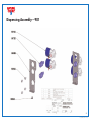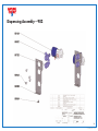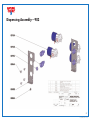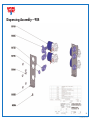
1
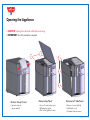
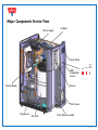
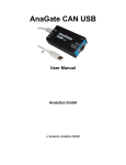
TECHNICAL SERVICE MANUAL
NCC7222-07 R2- 111207
Opening the Appliance
• CAUTION: Unplug from electrical outlet before servicing
• IMPORTANT: Torx 20 screwdriver required
Remove Faucet Cover
• Squeeze sides at
arrows and lift
Remove Top Panel
Remove Left Side Panel
• Loosen 2 screws at top, rear
• Pull panel up at rear
• Then roll to right front corner
• Remove 3 screws left side
• Slide back 1 inch
• Tilt panel down to remove
1
NCC7222-07 R2- 111207
Major Components Service View
Power Supply
Ice Bank
Touch Panel
LED/
SleepMode
Sensor
Control Board
LED1
LED2
Sleep
Mode
Sensor
Faucet
Filter Access
Compressor
Hot Tank
Front Panel Assembly
2
NCC7222-07 R2- 111207
Evaporator
InstaChill™ Cooling System
Water Coil
• Uses a 20’ length of 1/4” OD Water
Coil inside a Tank (called Ice Bank)
filled with water and ice.
Ice Bank
• No reservoir of drinking water.
• 3” thick slab of ice is formed on left
side of Ice Bank.
• Ice Bank Pump circulates water in the
Ice Bank, chilling the drinking water
inside the Water Coil.
• Ice Bank Pump is activated for
1 minute, every time Cold or
Sparkling water is dispensed.
Condensor
Fan
• Ice Bank Pump comes on automatically
for 1 minute, every 10 minutes.
• Level Sensor at front of Ice Bank
automatically fills and maintains
water level inside Ice Bank.
• Thermistor measures temperature inside
Ice Bank within 0.5 degree F.
Compressor
• Separate valve used to fill Ice Bank
(Part #: 6519)
3
NCC7222-07 R2- 111207
InstaChill™ Cooling System
Model 901
Model 902
Cold and Ambient
Cold and Hot
Inlet to Ice Bank
from Filter
Inlet to Ice
Bank from Fill
Valve
Stainless Steel Water Coil
Tee to Hot or Ambient
Water Valve
Alternate Location
for Cold Thermistor
Cold Thermistor
Evaporator
Ice Bank Pump
Level Sensor
4
NCC7222-07 R2- 111207
InstaChill™ Cooling System
Model 903
Model 904
Model 905
Cold and Sparkling
Cold, Hot and Sparkling
Cold, Hot and Ambient
5
NCC7222-07 R2- 111207
Water Pathway
The Water pathway inside the ION is sealed and pressurized
in 1/4” OD tubing (about 23’ total inside the appliance).
Inlet to Ice Bank
from Fill Valve
Inlet to Water
Coil from Filter
Tap Water supply tubing connects directly at the rear of the
appliance to an Inlet Valve.
Dispensing
Valves
After the Inlet Valve, the water is directed to the Filter.
After the Filter, the Water travels up to the Ice Bank
Assembly, where it is either chilled inside a Stainless Steel
water coil, or bypasses to Ambient, Sparkling, or Hot
Water tubing.
After the Ice Bank, water is directed to Dispensing Valves at
the outlet of the appliance for Cold, Ambient, Sparkling,
and Hot Water.
KEY LEARNING - when you press one of the icons on the
Touch Panel, you are opening both the Inlet Valve and one
of the Dispensing Valves. You will always hear TWO valves
opening and TWO valves closing, in quick succession.
This double click is important when troubleshooting the
appliance and finding a valve which may not be opening
or getting electrical current to open.
Inlet Valve
Faucet
Ice Bank
Fill Valve
6
NCC7222-07 R2- 111207
RapidHot™ Water System
FUNCTION – Water from Filter enters Ice Bank Assembly,
but is diverted with Tee fitting and bypasses the Ice Bank
Water Coil.
Blue Water Tubing from Ice Bank Assembly travels to Hot
Water Valve, attached to Hot Tank.
Filtered Water
Inlet to Hot Tank
Hot Valve
Outlet Tube
Vent Tube
Hot Water tank is not pressurized, but extremely dangerous
to service when filled with Hot Water. To cool, turn switch at
rear of appliance to OFF. Then dispense water from using
Hot Water icon on Touch Panel until water is cool. Then,
water can be drained from Hot Tank by removing
1/4” plug at bottom of Hot Tank elbow fitting.
MANUAL FILL – On first STARTUP only, the software will
force you to make sure the Hot Tank is filled. On every
subsequent STARTUP, make sure the ON/OFF Switch at
rear of appliance is in OFF position before connecting
electrical power.
TRANSPORTATION – It is not necessary to empty the
Hot Tank before transport, except in temperatures below
freezing. The only outlet for water is through the Faucet. The
Hot Tank contains about 4 lbs of water and can be emptied
to make the appliance lighter to carry.
Drain Plug
7
NCC7222-07 R2- 111207
ION Software
Revision Level
Date
Notes/Changes
A
July 30, 2006
Production Release.
SleepMode default is OFF
Filter Settings at 1,500 gallons and 12 months
B
August 13, 2006
Changed Compressor cycle times
C
October 27, 2006
Increased Hot Temperature settings
D
December 10, 2006
Minor coding change
E
April 15, 2007
Changed Ice Bank Pump ON time from 30 seconds to 60 seconds
SleepMode default is ON
F
May 31, 2007
Changed Level Sensor setting.
G
not implemented
H
June 6, 2007
Corrected Filter Reset button to change LED’s green
Filter Monitor Settings – default OFF
J
June 25, 2007
Compressor Max ON and REST times added
Added Model 900 (all dip switches DOWN)
Added Dispense Error code for 2 minute dispense and 12 times/minute
Added Compressor/Fan fail check … if temp not lower after 1 hour, then LED signal error
K
July 29, 2007
Changed Code to new processor
L
August 24, 2007
Corrected Compressor timing loops.
8
NCC7222-07 R2- 111207
Model Valves
901
Cold #6516
ELECTRICAL SCHEMATIC
Wiring Diagram
(rev1 - for models produced after April 15)
902
DANGER-RISK OF DEATH
903
WARNING-HIGH VOLTAGE ON
MAIN CONTROL BOARD.
ALWAYS UNPLUG POWER SUPPLY
TO UNIT BEFORE SERVICE.
904
905
Touch Panel
Location
Circuit Board
Location
C
D
C
D
C
D
C
D
B
C
D
B
Ambient #6516
Cold #6516
Hot #6517
Cold #6516
Sparkling #6516
Cold #6516
Hot #6517
Sparkling #6516
Cold #6516
Hot #6517
Ambient #6516
C
D
C
D
C
D
C
D
B
C
D
B
100000
010000
110000
001000
101000
GROUND
SCREW
TOUCH PANEL
ICE
BANK
PUMP
CONTROL BOARD
PART # 1784
HIGH
VOLTAGE
AREA
B
C
FUSE - ICE BANK
PUMP (0.5 AMP)
ICE BANK PUMP
RELAY (K3)
H2O
HEATER
A
DIP Setting
DIP chart reference - 0 is DOWN and 1 is UP
DIP positions 1, 2, and 3 control model setting
DIP positions 4, 5, and 6 are special function
contact factory for more information
D
6-CONDUCTOR
RIBBON CABLE
10-CONDUCTOR
RIBBON CABLE
TO J21
6-PIN CONNECTOR
LEDS (2)
PHOTO SENSOR
OPTIONAL INPUT
(UNUSED)
REF
COMP
FILTER RESET SWITCH
DISPLAY BOARD
PART # 1785
PIN 3 = BLACK
PIN 3 = RED
WHITE
BLACK
OVERLOAD
(YELLOW)
GROUND
SCREW
DIP SWITCH
OPTIONAL INPUT
(UNUSED)
PIN 2 = WHITE
PTC RELAY
(BLUE)
BLUE FAUCET LED
PIN 3 - BLACK
PIN 2
PIN 1 + RED
PIN 1 = WHITE
PIN 3 - WHITE
PIN 2 + RED
PIN 1
PIN 1 = BLACK
PIN 3 - WHITE
PIN 2
PIN 1 + RED
24 VDC IN (J1)
POWER INLET
SEE DATA PLATE FOR
INPUT SPECFICATION
POWER SUPPLY
100-240 VAC IN
24 VDC OUT
PIN 3
PIN 2 - WHITE
PIN 1 + RED
PIN 3
PIN 2 - WHITE
PIN 1 + RED
NEUTRAL
Natural Choice Corporation
Rockford, IL 61109
phone 815.874.4444
PIN 3
PIN 2 - WHITE
PIN 1 + RED
C
SPARKLING/AMBIENT #6516
AC LINE
VOLTAGE IN
L1
GROUND
PIN 3
PIN 2 - WHITE
PIN 1 + RED
HOT TANK
TEMP SENSOR (TM3)
ICE BANK
TEMP SENSOR (TM1)
SPARKLING/AMBIENT #6516
D
COLD #6516
ICE BANK
LEVEL SENSOR (TM5)
IEC SOCKET
ICE BANK
FILL VALVE
#6519
HOT #6517
PIN 4 = RED
24 VDC OUT
24 Volt DC
Components
COMPRESSOR
FAN
www.naturalchoicewater.com
B
INLET
VALVE
#6518
24 Volt DC
Components
All Rights Reserved, Natural Choice Corp.
9
NCC7222-07 R2- 111207
Troubleshooting Guide
Problem:
Water Dispenses from Cold or Sparkling Valve, but Water not Cold
page 11
No Water Dispenses From Cold or Sparkling Valve
page 12
Water dispenses from Hot Valve, but water not Hot
page 13
No Water dispenses from Hot Valve
page 14
Low or No Water Flow
page 15
Blue LED not ON
page 16
Blinking RED lights (both together, not alternating)
page 17
Steady Orange lights (never goes to blinking Orange lights)
page 18
Water Leak
page 19
Steady RED lights – Filter Change required.
When pressing Filter Reset button, does not reset RED lights to GREEN.
page 20
10
NCC7222-07 R2- 111207
Troubleshooting Chart
Problem: Water Dispenses from Cold or Sparkling Valve, but Water not Cold
Cause
Action
1. ION has been in SleepMode (with compressor off) for
weekend or long holiday.
1. Allow ice to build over 3-4 hour time period. Optionally,
program SleepMode to be OFF (Ice Bank to be maintained
24 hours per day).
2. ION is constantly in SleepMode
- is cooler in room with low level lighting?
- is Blue LED ON or OFF?
2. If Blue LED is OFF, this indicates ION is in SleepMode.
To lockout ION from SleepMode, see programming section in
Owners Manual.
3. ION may be plugged into outlet controlled by light switch.
3. Change Outlet and retest.
4. Is Fan operating?
4. Check wiring at Control Board.
5. Is Compressor Running?
5. Check wiring at Control Board
6. Freon Leak.
6. If no ice after 3 hours of Compressor and Fan operating,
call factory.
7. Software bug
7. Software Rev Level J and K have higher than normal incidence
of compressor malfunction – either freeze-up or no ice condition.
Call factory for replacement of product or new Circuit Board.
11
NCC7222-07 R2- 111207
Troubleshooting Guide
Problem: No Water Dispenses From Cold or Sparkling Valve
IMPORTANT – Do you hear both Inlet Valve and Cold Valve “double-click” when opening and closing?
Inlet Valve must open to allow water into ION. Dispensing Valve then allows water out of appliance.
Therefore, when dispensing water, you will hear two valves clicking open and closed in quick
succession. The clicking indicates the plunger is moving up and down and that the valve has electrical
current. Place your finger on the back of the appliance where Inlet Valve is located and you can feel it
click open and closed. Place your finger on Dispensing valve and you can also hear it click open and
closed. A dead valve (no electrical current) is indicated when you cannot feel the plunger moving
up inside.
Cause
Action
1. Dead Valve - No electrical current.
1. Check Touch Panel connector to Display Board,
behind Front Panel.
Check valve wiring on Control Board.
Check DIP Switch setting for correct ION model
(see wiring diagram).
2. Valves are clicking, indicating electrical current is present.
2. Double-check Water Supply tubing, shutoff valves, and undersink
connection.
Check inside Ice Bank for frozen Ice Bank … thaw and set
DIP 4 to UP position. Or contact factory for latest software
revision level.
12
NCC7222-07 R2- 111207
Troubleshooting Guide
Problem: Water dispenses from Hot Valve, but water not Hot
Cause
Action
1. ON/OFF switch at back of ION
1. Turn to ON position.
2. Wiring and connectors at Control Board
2. Check for continuity (not voltage) through the hot tank connector
and wiring harness at Control Board (with ION unplugged and
Switch in ON position).
3. Thermal Overload in Hot Tank Assembly has been tripped
(from dry-firing hot tank).
3. Replace Thermal Overload (this is very rare as the software does
not allow temperature to rise quickly inside hot tank). Instead you
will get an LED error message reminding you to fill the hot tank
and check the thermistor.
4. Faulty Control Board.
4. Replace Control Board.
13
NCC7222-07 R2- 111207
Troubleshooting Guide
Problem: No Water dispenses from Hot Valve
Cause
Action
1. Are customers pressing BOTH Hot and Safety button
at same time?
1. Refer to Instruction Label inside filter door of appliance
and notify customer.
2. Do you hear both Inlet and Dispensing Valve clicking
open and closed?.
2. Do you hear both Inlet and Dispensing Valve clicking
open and closed?
2. Check for dead valve or water supply problem.
Check DIP switches on Control Board (see wiring diagram).
Check Valve Wiring on Control Board (see wiring diagram).
14
NCC7222-07 R2- 111207
Troubleshooting Guide
Problem: Low or No Water Flow
IMPORTANT – Keep in mind that inside the ION, there is a 1 micron carbon filter and 23’ of 1/4” tubing (the Water
Coil is 20’ in length). Plan ahead for adequate water pressure and flow rate into the ION.
Cause
Action
1. Using 1/4” water supply tubing may restrict water flow, depending on available water pressure inside building.
1. Change to 3/8” water supply tubing.
2. Inlet Valve is quick connect fitting that requires cleanly cut 1/4”
water supply tubing.
2. Check water supply tubing and cut cleanly with razor knife.
3. Is copper tubing used at Inlet Valve?
3. Do not use copper tubing to connect to ION appliance … use
a 1/4” compression union fitting and only connect to ION with
plastic tubing.
15
NCC7222-07 R2- 111207
Troubleshooting Guide
Problem: Blue LED not ON
IMPORTANT – SleepMode is an energy saving feature that is programmed into the Control Board. A photo sensor
behind the LED3 on Front Panel allows software to turn the compressor OFF when room is dark.
Check the location carefully… if room light is turned ON and OFF frequently during the day, this will be a problem for
the cooling system. See Owners Manual, programming section, and program the SleepMode feature to be OFF.
When SleepMode is ON, compressor is OFF after room is dark for 5 minutes; hot tank drops to 135F. When any
button is pressed, OR in light room after 5 minutes, SleepMode cycle ends, and hot tank and compressor are both
ON as needed to reach temperature.
Cause
Action
1. Loose connection behind Front Panel at Display Board
1. Reconnect or replace as needed.
2. ION in SleepMode
2. In very low light, after 5 minutes, ION goes into SleepMode
(default setting) unless programmed OFF (see Owners Manual,
programming section).
16
NCC7222-07 R2- 111207
Troubleshooting Guide
Problem: Blinking RED lights (both together, not alternating)
IMPORTANT – Ice Bank automatically fills by using a Level Sensor. To prevent endless water flow from failed Level
Sensor, software only allows the Ice Bank to fill for 5 minutes on STARTUP. Once the ION has passed STARTUP, the Ice
Bank is limited to a fill time of 2 minutes. To fill the Ice Bank, you will need to unplug and reconnect the ION to
electrical outlet until the Ice Bank is filled.
Cause
Action
1. Level Sensor Timeout
1. Unplug ION and reconnect to electrical supply.
Continue as need until Ice Bank is filled and LED1 and LED2 are
both Green and Steady (with Blue LED under the faucet). This
indicates Normal Operation.
17
NCC7222-07 R2- 111207
Troubleshooting Guide
Problem: Steady Orange lights (never goes to blinking Orange lights)
IMPORTANT – on software rev level prior to L (Sept. 2007), a hot or cold sensor unplugged (or not completely
connected) will cause this condition. During shipping, the sensor connections can become unstable and may require
careful removal (straight back) and reinsertion onto the Control Board (see wiring diagram). CAUTION – unplug ION
before any contact with Control Board.
Cause
Action
1. Are Cold and Hot sensors (thermistors) in the correct position?
1. Check wiring diagram, remove, and reinsert. CAUTION - unplug
ION before any contact with Control Board.
2. On Models produced after September 1 … can you hear
a single initialization beep when ION is first plugged in?
2. If YES, then double check sensor wires and replace sensors
as needed.
If NO, then replace Control Board – programming error or defect
on Control Board (perhaps, shipping damage) is preventing
Control Board from initialization.
18
NCC7222-07 R2- 111207
Troubleshooting Guide
Problem: Water Leak
IMPORTANT – the ION uses an Inlet Valve to allow water to enter the appliance. Only when the customer presses
Touch Panel to dispense water – or when Ice Bank automatically fills – does the Inlet Valve open to allow water to enter
the appliance.
On units with “Bypass” feature, the Inlet Valve is bypassed to allow for Filter Water from the ION to be routed out the
back of the appliance and over to a coffee machine. This option provide for continuous water flow (bypassing the Inlet
Valve) and is not recommended for installations that want to maintain the maximum level of leak prevention.
Cause
Action
1. Filter not completely rotated into correct position.
1. Some filters (produced June 2007) have been spinwelded
incorrectly and can only be rotated clockwise into ION to a
certain point. If you want these filters replaced, contact the factory.
2. Ice Bank leak
2. Level inside Ice Bank is checked by software every 24 hours and
refilled (2 minute limit)… a small pinhole leak inside Ice Bank can
cause leak. Contact factory for replacement.
3. Tubing, Fitting, or Valve Leak
3. Check all fittings, tubing, and valves, and repair as needed.
19
NCC7222-07 R2- 111207
Troubleshooting Guide
Problem: Steady RED lights – Filter Change required.
When pressing Filter Reset button, does not reset RED lights to GREEN.
IMPORTANT – When changing filters, ALWAYS reset the filter monitor (time and gallons) to zero by pressing the Filter
Reset button until you hear a beep (about 6 seconds).
The Filter monitor works as follows: (1) Gallons (can be set for 750, 100, or 1,500 gallons) based on 0.5 GPM flow
rate; (2) Time (elapsed calendar time of 3 months, 6 months, or 12 months).
On models produced after June 2007, an optional setting of OFF for either Gallons or Time is available… see
Owners Manual for programming instructions.
Cause
Action
1. On units produced prior to June 2007, a software bug may not
allow the LED’s to be reset to GREEN.
1. Unplug the ION, and for first few seconds, the LED’s will start out
as GREEN, quickly press the Filter Reset button and gold until you
hear an audible beep.
LED’s will remain GREEN.
Contact factory if any further difficulty.
20
NCC7222-07 R2- 111207
Frame Assembly
21
NCC7222-07 R2- 111207
Display Valve Assembly (Models 903,904 only)
(for Models 903, 904 only)
22
NCC7222-07 R2- 111207
Filter Manifold Assembly
23
NCC7222-07 R2- 111207
Front Panel Assembly
24
NCC7222-07 R2- 111207
Dispensing Assembly – 901
25
NCC7222-07 R2- 111207
Dispensing Assembly – 902
26
NCC7222-07 R2- 111207
Dispensing Assembly – 903
27
NCC7222-07 R2- 111207
Dispensing Assembly – 904
28
NCC7222-07 R2- 111207
Ice Bank Assembly
29
NCC7222-07 R2- 111207
Final Assembly
30
NCC7222-07 R2- 111207