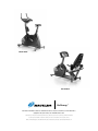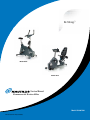
1
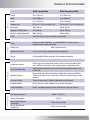
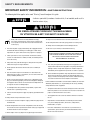
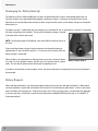
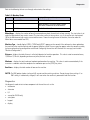
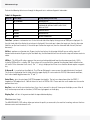
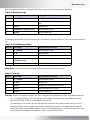
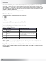
Be Strong.™
Model U916
Model R916
Service Manual
Commercial Series Bike
Model: U916 & R916
PN 001-6884 Rev B (03/27/2007)
Important—Please Read
This manual is intended for authorized Nautilus or Nautilus certified service personnel and not for the consumer.
There are no user serviceable parts. Servicing of the Nautilus® Commercial Series Bike by other than authorized
Nautilus or Nautilus certified service personnel may result in voiding of the warranty.
If you are a consumer and require technical support to resolve a problem with your Nautilus® Commercial
Series Bike, please call Nautilus® Customer Service at 800-628-8458 (North America) or +41-26-460-77-77
(outside North America).
Table of Contents
Product Specifications................................5
Important Safety Information...............6
Cable Connections - U916......................................53
Cable Connections - R916......................................56
Safety Warning Labels . ..........................................7
Appendixes.........................................................59
Maintenance........................................................9
Required Tools........................................................60.
Using a Multimeter................................................61
Maintenance Records........................................... 11
International Power Plug Configurations...............64
Resetting the Maintenance Hour Timer................ 11
Routine Maintenance............................................ 11
Warranty Information....................................................65
Checking the Battery Charge................................ 11
Contact Numbers..........................................................67
Recharging the Battery Back-up........................... 12
Battery Disposal.................................................... 12
Console Codes.................................................13
Overview................................................................15
Defaults..................................................................15
Customize...............................................................15
Machine Status......................................................16
Diagnostics.............................................................17
Maintenance Logs..................................................18
Machine Configuration...........................................20
Electrical Troubleshooting. .....................21
U916/R916 Main Wiring Diagram ........................23
U916 Console Heart Rate Wiring Diagram............24
R916 Console Heart Rate Wiring Diagram............25
General Bike Electronics Troubleshooting.............26
Mechanical Troubleshooting.................35
Removing/Replacing Parts -.
U916 and R916 Common Parts..............................37
Removing/Replacing Parts -.
U916 Parts..............................................................48
Removing/Replacing Parts -.
R916 Parts..............................................................51
Nautilus® Commerical Series Bike Service Manual Contents
Functionality
Electrical
Physical
product specifications
U916 Upright Bike
R916 Recumbent Bike
Length
45 in. (114.3 cm)
67 in (170.18 cm)
Width
24 in. (60.96 cm)
24 in. (60.96 cm)
Height
57 in. (144.78 cm)
46 in. (116.84 cm)
Workout Area
50” W x 81” L (127 cm x 205.74 cm)
50” W x 103” L (127 cm x 261.62 cm)
Unit Weight
150 lb. (68 kg)
180 lbs (82 kg)
Shipping Package Weight
178 lb. (81 kg)
231 lbs (105 kg)
Max User Weight Supported
400 lb. (182 kg)
400 lb. (182 kg)
Belt(s)
Two: Poly-V (6V) self-tensioning belt and timing belt
Power
Cordless; or 108-132VAC 60 Hz, or 220-240VAC 50 Hz, 20 watts maximum
(operation with charger connected)
Battery Type
Battery Charge Time
8 hours to full charge, starting with discharged battery
Display
C51 blue/white LCD with backlight. Tactile membrane keypanel
Number of Functions
Eleven: Heart rate, elapsed time, calories burned, calories burned per hour,
watts, METS, resistance level, rpm, speed, distance, and workout profile
Heart Rate Monitoring
Integrated heat rate monitoring system with polar-compatible wireless and
contact HR
Workout Programs
Eleven: Quick Start, Manual, Fat Burner, Calorie Burner, Intervals, HR Zone
Trainer, multi-stage Fit Test. Calorie Goal, HR Intervals, Random Play, Custom
Intervals
Resistance Range
Twenty: 20 watts (level 1, 20 rpm) to 500 watts (level 20, 80 rpm)
Language Options
English, German, French, Spanish, Italian, Dutch, Portuguese
C-Safe Compatible
Level 2 compatible. Owner/manager will be able to customize console.
Operating Temperature
Environmental
6VDC sealed lead-acid
Storage Temperature
o
o
50–90 F (10–32 C)
o
-25–50 C
Operating Humidity (noncondensing)
3–95% relative humidity
Storage Humidty (noncondensing)
3–95% relative humidity
Nautilus® Commerical Series Bike Service Manual safety requirements
Important Safety Information:
SAVE THESE INSTRUCTIONS
The following definition applies to the word “Warning” found throughout this guide:
7! 2 . ) . '
$!.'%2
- Indicates a potentially hazardous situation which, if not avoided, could result in
death or serious injury.
7! 2 . ) . '
This symbol appearing throughout this manual means
Pay Attention! Be alert! Your safety is involved!
!4 4 % . 4 ) / .
$!.'%2
1. R
ead, understand and carefully follow all warnings,
instructions and procedures in this manual. Failure to do
so can produce a serious electrical shock hazard or other
)--%$)!4%!#4)/.2%15)2%$
serious injury.
#!54)/.
2.The external power supply should always be unplugged from the
AC wall outlet before removing or installing parts. Never make
adjustments or repairs while an exercise program is in progress.
14. Keep the area underneath and around the machine clear.
15. Do not operate where aerosol (spray) products are being used.
16. Always wear insulated gloves when handling batteries.
17. Do not crush, incinerate, or dismantle the battery.
!4 4 % . 4 ) / .
3. Close supervision is necessary whenever the machine is being
used or serviced whenever children, invalids, or disabled persons
are in the vicinity.
The electrolyte contains sulfuric acid, which can
cause serious damage to eyes and skin. Should
this occur, flush profusely with water
and seek medical attention.
4. Keep hands away from all moving parts. Keep feet on the pedals
while exercising or testing the machine.
)--%$)!4%!#4)/.2%15)2%$
18.The safety level provided by the design of this equipment can
5. Do not operate the machine with the side covers removed, or
outdoors.
only be maintained when the equipment is regularly examined for
damage and wear. Inoperable components should be replaced
immediately or the equipment be put out of use until it is repaired.
#!54)/.
6. Use this machine only for its intended use as described in this
Manual. Do not use parts, attachments, or accessories other than
those provided by Nautilus, Inc.
7. Do not use the external power supply if it has a damaged cord or
plug, it is not working properly, if it has been dropped or damaged,
or dropped in water. Contact our Technical Service Department to
arrange for the return of damaged parts.
8. To avoid potential safety and electrical problems, replace with
manufacturer’s specified parts only.
9. Connect the external power supply to a properly grounded AC wall
outlet.
10. Keep all cords away from heated surfaces.
11. To disconnect the external power supply, remove the plug from the
AC wall outlet.
12. Do not let liquid enter the console. If liquid does enter the console,
the console must be inspected and tested for safety by an approved
technician before it can be used again.
13. Never drop or insert any object into any opening on the machine.
19.Failure to follow the guidelines may compromise the effectiveness
of the exercise experience, expose you (and possibly others) to
injury, and reduce the longevity of the machine. Follow all training
instructions listed in the manual and/or on the machine.
Failure to follow the conditions set forth below shall limit, to the extent
allowed by law, Nautilus, Inc. responsibility for the safety, reliability,
and performance of this equipment.
• The operator manual must be read in full by each owner and trainer
before the product is first used. Each user must be instructed in the
proper use of the bike and its accessories.
• The equipment must be used in accordance with the instructions
for use.
• Only Nautilus-trained or Nautilus-authorized personnel should
carry out assembly operations, extensions, readjustments,
modifications, or repairs.
• For further information or instruction on use, maintenance or
specifications, please contact your Authorized Nautilus Fitness
Dealer or Service Technician.
Safety Warning Labels
The following safety warnings are located on the Nautilus® Commercial Series Bike. Please read all safety precautions and
warning information prior to using your product. Be sure to replace any warning label if damaged, illegible, or missing. If
you need replacement labels, please call a Nautilus Representative at (800) 628-8458 (North America) or +41-26-460-77-77
(International office).
Label 2
Label 1
Label 2
Label 1
Nautilus® Commerical Series Bike Service Manual Safety Warning Labels
The following safety warnings are located on the unit. Please review and understand the safety warning labels and their
locations on the unit prior to use.
If you do not have, or cannot find, or need to replace a warning label please call 1-800-628-8458 (North America) or .
+41-26-460-77-77 (International office) to obtain a new label.
Label 1: See Figure 1 for general warning label.
Location: The warning label in Figure 1 is located on the
side of the console mast.
Figure 1
Label 2: S
ee Figure 2 for general exercise warning label.
Figure 2
Location: Affixed to the console face below the keypanel.
1
Maintenance
Contents
Maintenance Records.................................................................................. 11
Resetting the Maintenance Hour Timer...................................................... 11
Routine Maintenance.................................................................................. 11
Checking the Battery Charge....................................................................... 11
Recharging the Battery Back-up.................................................................. 12
Battery Disposal........................................................................................... 12
Nautilus® Commerical Series Bike Service Manual 10
Maintenance
Maintenance Records
For ease of maintenance the U916 and R916 console will keep track of hours, number of workouts, time between last
servicing, etc. You can quickly access any of the custom menus by pressing [LEVEL: UP], [4], [ENTER]. The console will
then display “MACHINE STATUS.” Use the [Level: UP] and [Level: DOWN] keys to scroll through the options. For details,
refer to the Machine Status Console Codes.
Resetting the Maintenance Hour Timer
After each maintenance period reset the counter. Press [LEVEL: UP], [7], [ENTER]. Then use the Level keys to scroll
through the options. When “MAINT HOURS” is displayed, press [ENTER]. Press the [0] key, then press [ENTER]. Press
[CLEAR] to return to the opening screen.
Routine Maintenance
Upon receiving your machine, use a soft, clean towel to wipe off the dust, which may have accumulated during shipping.
Your new machine will require minor assembly. Refer to the “Installation Instructions” section for details.
Cleaning
1.DO NOT USE GLASS CLEANERS OR ANY OTHER HOUSEHOLD CLEANERS ON THE CONSOLE. Clean the console daily
with a water-dampened cloth and wipe dry after cleaning.
2.Clean the exterior of the machine daily using soap and water or a diluted, non-mineral based household cleaner such
as Fantastic®.
Inspection
1. F rame: Inspect the frame for any rust, bubbling, or paint chips during the weekly cleaning. The salt in perspiration
can damage the unpainted surfaces. Repair the damaged area with a touch-up paint kit purchased from Nautilus (call
Customer Service for order information).
Checking the Battery Charge
1.Using your multimeter, touch the red lead to the positive terminal of the battery and the black lead to the negative
terminal.
2.
If the voltage level is less than 6.1 VDC, charge the battery.
Nautilus® Commerical Series Bike Service Manual 11
Maintenance
Recharging the Battery Back-Up
The Commercial Series U916 and R916 bikes are both self-powered (cordless) with a rechargeable battery back-up.
Typically, the bike can be operated without plugging in the battery charger. If, however, the console flickers during
operation or the console display does not light up while using the machine, then use the battery charger to recharge the
battery back-up.
The battery charger is supplied with the unit and plugs into a standard 115 volt, 15 amp outlet, or a 220 volt, 15 amp outlet.
(All major voltage plugs are available.) The plug-in for the battery charger is located
in the front of the machine at the base.
NOTE: If installing the optional LCD Monitor, refer to the NV915 installation manual at
this time.
Plug the wall pack battery charger into the connector and charge the battery for
approximately 24 hours and then recheck it. It is okay to use the machine while the
battery charger is connected.
When the bike is not connected to an external power source, the console will power
on as the user starts to pedal machine, and will stay lit for up to 60 seconds in pause
mode. The console will power off after 60 seconds of stopping exercise.
Battery charger plug-in
If the bike is connected to an external power source, the console will power on automatically and stay on until power is
disconnected.
Battery Disposal
When ordering new batteries, you will need to properly dispose of (recycle) your old lead-acid batteries. Most federal
and state regulations require lead-acid batteries to be recycled. Do not throw away old batteries. Lead is a toxic heavy
metal, hazardous to living organisms. Disposal instructions and a list of recycling centers are tabulated in the Appendix.
If you have questions, contact the Customer Service Department at 800-628-8458 (North America) or +41-26-460-77-77
(International office).
12
2
Console Codes
Contents
Overview...................................................................................................... 15
Defaults........................................................................................................ 15
Customize..................................................................................................... 15
Machine Status............................................................................................ 16
Diagnostics.................................................................................................. 17
Maintenance Logs....................................................................................... 18
Reset Maintenance Hours....................................................................... 19
Error Log.................................................................................................. 19
Machine Configuration................................................................................ 20
Nautilus® Commerical Series Bike Service Manual 13
14
Customization
Overview
To enter a Service Mode, the unit must be in IDLE DISPLAY state or an ERROR. The service screens cannot be entered during
a workout, paused or in a WARNING state. (If the unit is in a Warning state, you must press [CLEAR] before entering the
Service Modes.) To access the console codes, press the Level Up button (▲), the group number code, and [Enter]. Then use
the arrow buttons to scroll through the menu options for each group. The procedures are outlined in the tables below.
There are six groups of Service Mode console codes: Defaults (codes starting with 2), Customize (codes starting with 3),
Machine Status (codes starting with 4), Diagnostics (codes starting with 6), Maintenance Logs (codes starting with 7), and
Change Machine (codes starting with 8). Each group of codes is defined below.
Defaults
You can customize several workout parameters on the R916/U916 Bike with default values to conform to your individual
requirements, including:
• % target heartrate (10-90%)
• age (10-99)
• workout time (5-99 min)
• workout level (1-20)
• weight (50-400 lbs. or 25-180 kg)
Refer to the following table to scan through and customize the settings:
Table 2–1. Defaults
Step No.
Press Keys
Display (What you will see)
1
▲, 2, ENTER
DEFAULTS
2
▼ or ▲
CHR PERCENT, AGE, TIME, LEVEL, WEIGHT
3
ENTER
Selected choice
4
▼ or ▲ (or numeric keypad)
Default value changes
5
ENTER
DEFAULTS
6
clear
SELECT WORKOUT
Customize
You can customize several console settings on the R916/U916 Bike with default values to conform to your individual
requirements, including:
• resetting all configurable settings to factory defaults (see below)
• adjusting lower screen contrast (0-15)
• adjusting upper screen contrast (0-15)
• console language
• choosing type of heartrate inputs (description below)
Nautilus® Commerical Series Bike Service Manual 15
Machine Status
• change units (USA units or metric units)
• cooldown time (1-10 min)
• maximum time limit (10-99 min or OFF)
Refer to the following table to scan through and customize the settings:
Table 2–2. Customize
Step No.
Press Keys
Display (What you will see)
1
▲, 3, ENTER
CUSTOMIZE
2
▼ or ▲
SET DEFAULTS, CONTRAST ADJ LOWER,
CONTRAST ADJ UPPER, LANGUAGE,
SELECT STATS*, HR INPUTS, CHANGE
UNITS, COOL DOWN, MAX TIME LIMIT
3
ENTER
Selected choice
4
▼ or ▲ (or numeeric keypad)
Default value changes
5
ENTER
CUSTOMIZE
6
clear
SELECT WORKOUT
*The Select Stats menu display option is not active for the R916 and U916.
Set Defaults – resets the machine to the factory defaults for all configurable values. Please note that selecting this option
will require the machine to be reconfigured (see Change Machine section).
NOTE: All error and history counter data (Maint Hours, Distance, Workouts, Run Hours, Error Log, and QA ID Number) will
be lost if Set Defaults is selected.
HR Inputs – enables the various heart rate inputs that can be used. Heart rate configurations include: Locked Inputs (both
heart rate monitors are read until it detects a valid signal to lock on, at which point the other HR inputs are ignored), HAND
HR PRGM OFF, Both HR OFF, Hand Only, Telemetry Only, and Either Input (if one input is lost, then the other input may
become active).
Change Units - changes all displayed data (service information and user data) to the selected units. Units are: Miles or
Kilometers, MilesPerHour or KilometersPerHour, Pounds (LB) or Kilograms (KG), MinutesPerMile or MinutesPerKM.
Machine Status
Use the machine status codes to view maintenance information such as:
• maintenance hours
• machine type (U/R916)
• console software version
• distance traveled
• number of workouts
• machine run-time hours
16
Diagnostics
Refer to the following table to scan through and customize the settings:
Table 2–3. Machine Status
Step No.
Press Keys
Display (What you will see)
1
▲, 4, ENTER
MACHINE STATUS
2
▼ or ▲
MAINT HOURS, U/R916 [or other], CONS,
DISTANCE, WORKOUTS, RUN HOURS
3
CLEAR
SELECT WORKOUT
Maint Hours – displays the number of hours (incremented every hour) the machine has been running. The start value is set
under the Maintenance Logs service screen. (The start value can be set to any value—e.g. if the service tech had entered
100 in the Maintenance Logs service screen and there was 1 hour of running time on the machine, the value under this
Maint Hours screen would read 101).
Machine Type – should display U/R916. “NTM Config REQD” appears on the console if the software has been updated on
the machine or the machine froze up and the power had to be cycled. The message also appears when the console assembly
has been replaced and no configuration established. Configuring the machine will eliminate this message (see the table
“Machine Configuration”).
Distance – displays the total distance in miles (or kilometers) of machine operation. This value is auto-incremented every
1/100th or 1/10th unit, depending on how many miles/km have accrued.
Workouts – displays the total number of workouts performed on the machine. This value is auto-incremented only if the
user enters a workout and either completes the workout or presses the [Stop] key twice.
Run Hours – displays the total number of hours on the machine.
Note: The R&D options (codes starting with 5) are not used for servicing machines. Do not change these settings. If an
R&D setting is inadvertently changed, it will reset when the machine is powered off and then back on.
Diagnostics
Use diagnostic codes to test various components of the machine such as the:
• tachometer
• alternator
• I/O
• sensor (for EV9.16 only)
• serial ports
• keypad
• display
Nautilus® Commerical Series Bike Service Manual 17
Maintenance Logs
Refer to the following table to scan through the diagnostic tests and view diagnostic information:
Table 2–4. Diagnostics
Step No.
Press Keys
Display (What you will see)
1
▲, 6, ENTER
DIAGNOSTICS
2
▼ or ▲
TACH TEST, ALT TEST, I/O TEST,
A SENSOR B, SERIAL PORTS, KEY TEST,
DISPLAY TEST
3
ENTER
Selected choice
4
CLEAR
DIAGNOSTICS
5
CLEAR
SELECT WORKOUT
Tach Test – performs a tachometer test. On the left hand side of the display the target rate of 2000 rpm is displayed. On
the right hand side of the display the actual rpm is displayed. If the actual rpm is above the target rate, then the alternator
field turns on (the level increases). If the actual rpm is below the target rate, then the alternator field shuts off (the level
decreases).
Alt Test – performs an alternator test. By pressing the level up key, the alternator field will turn on and the steps will
become harder to rotate. By pressing the level down key, the alternator field will turn off and the steps will become easier to
rotate.
I/O Test – The AUX and B+ values represent the current and voltage delivered from the alternator respectively. AUX is
scaled by 1000 and B+ is scaled by 300. These values will increase with the speed of the alternator (note that both values
will reach 0 if the alternator is left at rest). The “---” string is displayed at all times since the bikes do not require a magnetic
key.
A Sensor B – is used only on the ellipticals. The A Sensor B diagnostic screen ensures the optical detector is functional.
The A value is displayed on the left hand side of the upper display (B is not used on the EV9.16). Under normal conditions,
the A value should toggle between the “0” and “1”.
Serial Ports - tests the serial ports (UARTS) for proper functionality. The tech can choose from either the CSAFE-1
Loopback or TM Loopback tests. Both of these tests result in PASS or FAIL. Please note that a null modem must be used to
perform these tests.
Key Test - tests all of the user interface keys. Once a key is pressed, its value will show up on the display screen. After all
keys have been pressed and are functional, a PASS message appears on the display.
Display Test - will test all segments on both the top and bottom displays.
Maintenance Logs
The MAINTENANCE LOGS settings allow you to view the quality assurance data, the machine’s error log, and reset the time
between service and maintenance calls.
18
Maintenance Logs
Refer to the following table to scan through the Maintenance Logs tests and view diagnostic information:
Table 2–5. Maintenance Logs
Step No.
Press Keys
Display (What you will see)
1
▲, 7, ENTER
MAINTENANCE LOGS
2
▼ or ▲
QA ID NUMBER*, MAINT HOURS, ERROR
LOG
3
ENTER
Selected choice
4
CLEAR after viewing (or reset)
MAINTENANCE LOGS
5
CLEAR
SELECT WORKOUT
* The QA ID NUMBER option is not used for servicing machines in the field.
The following tables provide the steps for resetting the time between service or maintenance calls, and for viewing the error
log:
Table 2–6. Reset Maintenance Hours
Step No.
Press Keys
Display (What you will see)
1
▲, 7, ENTER
MAINTENANCE LOGS
2
▼, ▼
MAINT HOURS
3
ENTER
MAINT HOURS
4
CLEAR to exit after viewing, or
0, ENTER to reset
MAINTENANCE LOGS
5
CLEAR
SELECT WORKOUT
####
Maint Hours – lets the service technician enter a value representing the maintenance hours.
Table 2–7. Error Log
Step No.
Press Keys
Display (What you will see)
1
▲, 7, ENTER
MAINTENANCE LOGS
2
▼, ▼, ▼
ERROR LOG
3
ENTER
NO ERROR or the highest priority error
4
▼ or ▲
Scrolls through the error log list
5
CLEAR
SELECT WORKOUT
Error Log – displays fatal errors accrued on the system. The log holds up to 8 error entries. Errors are handled in two ways:
First, as a non-fatal Warning, which will display the error response text but continue system operation until you
press the [Clear] key. Warnings are not logged in the Error Log.
The second way is a fatal Error, which will stop the exercise and return the system to an idle intensity state. The
console will display the error response and a number showing how many errors were logged during the specific
event. (Some errors trigger multiple responses). To view the non-displayed errors, access the Error Log. The unit will
not let you restart the program unless power has been turned off and then back on.
n
n
Nautilus® Commerical Series Bike Service Manual 19
Machine Status
Once you access the Error Log, you can cycle the display through 8 entries by using the up/down keys. Each entry displays
the error label, its position in the log (1-8), and the time (hours) the error occurred. Note that the most recent error might
not be in log position 1—as the number of errors exceeds 8, the newest error will overwrite the oldest. In addition, if a new
error is identical to the log’s previous entry, the system checks the time. If the time is the same (within minutes), the error is
not logged, to help prevent redundant errors.
The only way to reset the Error Log is to reconfigure the machine.
Machine Configuration
Use Machine Configuration to change the machine type. The choices are:
• Stepper
• StepMill
• U/R916
• Elliptical
In general, only the U/R916 machine type is used for the U916 or R916.
Refer to the following table to scan through and customize the settings:
Table 2–8. Machine Configuration
Step No.
Press Keys
Display (What you will see)
1
▲, 8, ENTER
CHANGE MACHINE
2
ENTER
U/R916
3
▼ or ▲
NTM CONFIG RQD, STEPPER CL, STEPMILL,
ELLIPTICAL, U/R916
4
ENTER
Selects your choice
5
CLEAR
SELECT WORKOUT
NTM Config RQD – resets the machine to a “blank” configuration. The configuration must be set to Elliptical (or other
machine type) for the workout functions to operate.
Stepper CL – configures the machine as a cordless Stepper. Please note that there is a sense line to let the software
know if the system is a Stepper PT (corded); if the system is indeed a Stepper PT, then Stepper PT will appear in the screen
instead of Stepper CL.
20
3
Electrical Troubleshooting
Contents
U916 and R916 Main Power Wiring Diagram......................................... 23
U916 Console Heart Rate Wiring Diagram............................................. 24
R916 Console Heart Rate Wiring Diagram............................................. 25
General Bike Electronics Troubleshooting............................................... 26
Contact Heart Rate Testing..................................................................... 28
Battery Charge Testing............................................................................ 29
Alternator Testing.................................................................................... 30
Start-Up Circuit Testing........................................................................... 31
Load Resistor Testing.............................................................................. 32
Shut-Down Testing.................................................................................. 33
Nautilus® Commerical Series Bike Service Manual 21
Electrical Troubleshooting
22
!,4%2.!4/2
"!44%29
7()4%
"2/7.
7()4%"
",!#+
'2/5.$
U916 and R916 Main Power Wiring Diagram
",!#+
7()4%
52-AIN0OWER7IRING
%840/7%2
30%%$
3%.3/2
467)2%
2%3)34/2
U916/R916 Main Power Wiring Diagram
Nautilus® Commerical Series Bike Service Manual 23
24
RED
FRONT
GRIP
001-6349
(PCBA)
"DISPLAY LOCK
QUICKSTART"
BLACK
REAR
GRIP
40465
LEFT HANDGRIP
BLACK
REAR
GRIP
001-6349
(PCBA)
"LEVEL (UP) - (DOWN)"
40466
RIGHT HANDGRIP
001-5378
U916 Console Heart Rate Wiring Diagram
RED
FRONT
GRIP
U916 Console Heart Rate Wiring Diagram
NAUTILUS
GREEN
001-5378
40679
WHITE
FIXED "T-BAR" CONTACT
HEART RATE GRIPS
BLACK
RIGHT
41700 (CONSOLE)
RED
LEFT
TO BIKE
POWER ELECTRONICS
AND ALTERNATOR
25473
41702
41187
(TELEMETRY SENSOR)
U916 Console Heart Rate Wiring Diagram
NAUTILUS
BLACK
REAR
GRIP
BLACK
REAR
GRIP
001-6349
(PCBA)
"LEVEL (UP) - (DOWN)"
40466
RIGHT HANDGRIP
RED
FRONT
GRIP
R916 Console Heart Rate Wiring Diagram
RED
FRONT
GRIP
001-6349
(PCBA)
"DISPLAY LOCK
QUICKSTART"
40465
LEFT HANDGRIP
001-5100
R916 Console Heart Rate Wiring Diagram
001-5110
RIGHT
41703 (CONSOLE)
LEFT
TO BIKE
POWER ELECTRONICS
AND ALTERNATOR
25473
41702
41187
(TELEMETRY SENSOR)
R916 Console Heart Rate Wiring Diagram
Nautilus® Commerical Series Bike Service Manual 25
General Bike Electronics Troubleshooting
Perform
general bike
electrical
testing
With external
power removed,
pedal the bike at
25RPM or greater
Does
the console
turn on?
This section applies to both
Contact Heart Rate and
Telemetry sensing
No
No
Is
battery in a
charged state?
Yes
Yes
Hold both Contact
Heart Rate grips
firmly
Remove plastic
shrouds so
electronics can be
observed
Does a
heart symbol
appear
Have a helper
pedal bike at 25
RPM or greater
No
Using external
power supply,
charge battery for
8 hours
Yes
No
Perform Contact
Heart Rate Testing
In 10S
or less, does the
heart beat?
Yes
On the console,
press "Quick Start"
to enter a manual
workout
No
Perform Alternator
Testing
Is an
increase in
resistance felt?
Yes
On the 27451
PCB, measure the
voltage on J1 pins
2 and 3
Is
battery voltage 6V
or greater?
26
Perform Battery
Charge Testing
Yes
On the 27451
PCB, measure the
voltage on J5 pins
1 and 10
Is
voltage here 6V
or greater?
Yes
2
No
3
No
Perform Start-Up
Circuit Testing
General Bike Electronics Troubleshooting
Continuation of General Bike Electronics Troubleshooting
2
Does
the resistance feel
smooth?
3
Remove 4 screws
holding console to
mast
No
Perform Alternator
Testing
Yes
Increase RPM and
levels until firm
resistance is felt
Is
firm resistance
felt?
No
Perform Load
Resistor Testing
Yes
Stop pedaling, and
press stop twice if
workout results
are desired
Using OHM Meter,
perform continuity
check on main
interface cable,
using wire colors
as a guide
Is
continuity OK?
No
Yes
Approximately 1
minute after
pedaling stops, the
console should
shut off
Did
the console shut
off?
While noting
locations, carefully
unplug all
connections to
console coming
from mast
Replace console
Replace main
interface cable
No
General bike
electrical testing
Yes
Perform ShutDown Testing
Bike Is Operating
Properly!
Nautilus® Commerical Series Bike Service Manual 27
Contact Heart Rate Testing Contact Heart
Rate Testing
Remove the
screws securing
the Contact Heart
Rate plates
Turn on console,
by either pedaling
bike, or installing
external power
supply
Remove 4 screws
holding console to
mast
Using volt meter,
measure voltage
potential on ALL
Contact Heart
Rate plates
While noting
locations, carefully
unplug the suspect
Contact Heart
Rate cable
When performing
measurement,
confirm positive
lead is on top plate
(users' palm)
Is a
voltage of about 2V
measured?
No
Using OHM Meter,
perform continuity
check on cable,
using wire colors
as a guide
Yes
No
Remove the
screws securing
the Contact Heart
Rate plates
No
Reverse the
polarity of the
plates' wires. Red
should be on top,
black on bottom
Is
the voltage
positive?
Is
continuity OK?
Yes
Yes
Have you had
success previously with
Contact Heart Rate
Systems?
*
No
Replace Contact
Heart Rate cable
Yes
General bike
electrical testing
Replace console
Perform Contact
Heart Rate Testing
* Contact Heart Systems perform properly on roughly 87% of the population, according to latest data from Salutron. Many factors affect the
pulse strength at the user's palms.
28
Battery Charge Testing
Battery
Charge
Testing
Measure the
voltage of the
contacts of this
connector on pins
1 and 2
Remove the
battery connector
from the 27451
PCB at location J1
Is
the voltage 9V
+/- 10%
Apply power to the
bike from the
external power
supply, first
confirming AC
voltage is present
Yes
Replace the 27451
PCB
Measure the
voltage on the
27451's J1 pins 2
and 3
Is
the voltage 6.8V
+/- 3%
Yes
No
Unplug the power
supply and
measure its
voltage on pins 1
and 2
Is
the voltage 9V
+/- 10%
No
Yes
No
Replace the
external power
cable
Measure the
voltage on test
points 1 and 3 of
the 27451
Replace the power
supply
Replace the
battery
Is
the voltage 9V
+/- 10%
Charge the battery
for 8 hours, or until
6.8V is achieved
No
Yes
General bike
electrical testing
Replace the 27451
PCB
Unplug the
external power
supply cable at
location J3
Charge the battery
for 8 hours, or until
6.8V is achieved
General bike
electrical testing
Due to requiring many pieces of test equipment, this procedure does not test the complete functionality of the charger but rather its final "float" state.
If the battery voltage is less than 3V, no more than 50mA is applied. From 3V to 6.8V current control applies nearly .4A until voltage control or float
state is entered.
Batteries can only be tested under load. Even if it measures 6V or more unloaded, it can still produce little or no voltage under load as a defective
battery's internal impedance increases.
Nautilus® Commerical Series Bike Service Manual 29
Alternator Testing
To minimize the complexity of the flowchart, this section will best be described in terms of system theory.
The colored connections to the alternator are as follows:
White-B+ — Alternator output voltage
Brown-Field — Alternator Control Current
Black-Ground — Alternator return
Prior to proceeding with tests below, perform continuity checks on the alternator cable, and confirm cable is securely
fastened to the alternator and the 27451 PCB.
For workouts that require levels of less than 50W resistance to the user, clinical mode must be used. In this condition,
the console is powered by an external power supply, and the alternator is not powered unless the user decides to
achieve levels of 50W or more.
If the bike’s speed is 40 RPM or greater, and assuming clinical mode is not desired, the system can subject the user
to a workout that is self-generating. Under self-generating conditions, the alternator is on; it is powering itself, the
console, and providing charge to the battery.
Prior to entering workout information, it is desired to have the user subjected to minimal resistance, and the console
is powered by the battery. Once the console knows all the user’s desired information, it turns on the alternator. The
alternator is turned on by a logic low on pin 2 of J5 of the 27451 PCB. This signal is also accessible on the 27451’s TP11.
Once the alternator is powered, the user sees an increase in resistance due to the alternator’s internal magnetic fields.
The 27451 PCB maintains a regulated voltage on the alternator’s B+ by varying the amount of current sourced into the
alternator’s field. B+ is sensed by the 27451, and the field current is altered until the alternator is at the desired voltage.
As the RPM increases, the alternator’s efficiency increases, and less field current is required.
Depending on the desired resistance level, the console can control the alternator’s output voltage by controlling the
logic level of pin 7 of J5 on the 27451 PCB. A logic low on pin 7 tells the 27451 to control at 7.8V or a logic high sets
9.8V.
If the alternator is not powering on, first confirm the bike is cranked at ~50 RPM, and that pin 2 of J5 (TP 11) is NOT
high. If it is, and a workout has been entered, suspect the console. If pin 2 of J5 is low, measure the alternator’s field
voltage. Without B+ the 27451 will attempt to force full current into the field, and in this condition it will be limited by
its input voltage, or the battery in this case. Therefore, if 5V or more is measured on the field with no B+, either B+ is
shorted or the alternator is defective. Before replacing the alternator, disconnect the B+ wires from the alternator’s
B+ terminal and see if an output voltage exists. If voltage is now present, which could easily exceed 30V in an uncontrolled state, the 27451 PCB is probably defective. With no load on B+, 5V or more field current, adequate RPM and no
B+, replace the alternator.
If no field voltage is detected, disconnect the B+ connections on the alternator, along with the field wire. Measure
the field resistance to alternator ground, which should be approximately 4 ohms which is a typical value of Prestolite
units. If the field resistance is way less than this or shorted, replace the alternator. If the field measures ~4 ohms, take
a jumper wire, and make a connection from the positive battery terminal to the alternator’s field tab. If the voltage now
jumps up to a level of 20 to 30V the alternator is good, and the 27451 needs replacing.
If the B+ voltage is sporadic first look for loose connections. This type of problem could be caused by a defective
alternator or 27451. If a known-good 27451 unit is available it will be the easiest component to replace. If the problem
goes away, confirm the other PCB still causes sporadic behavior, and the problem was not in fact a loose connection.
30
Start-Up Circuit Testing
Start-Up
Circuit
Testing
Connect external
power supply
Does
Console turn
on?
No
Using the Battery
Charge Testing
section as a
reference, confirm
operation of
external power
supply and
external power
cable
Yes
Unplug external
power supply
Confirm the
magnetic pick-up
on the alternator is
mounted such that
its face is parallel
and within 1mm of
every fin on the
speed disk
Adjustment
required?
Yes
Tighten magnetic
pick-up securely,
and confirm the
sensor is free of
contact from the
sensor
9V +/- 10%
measured on TP1?
No
Yes
Unplug the speed
sensor from the
27451 at J2
~8V
measured on J5
#1?
No
No
Yes
Have a helper
pedal bike at 25
RPM or greater
while measuring
the AC voltage on
J2 pins 1 and 2
Replace 27451
PCB
Perform continuity
check on main
interface cable,
pins 1 and 10
General bike
electrical testing
Voltage
measure 4VAC
or more?
Continuity
OK?
No
Yes
Replace 27451
PCB
No
Yes
Replace the
magnetic pick-up
Replace console
Replace or repair
main interface
cable
General bike
electrical testing
Nautilus® Commerical Series Bike Service Manual 31
Load Resistor Testing
Load Resistor
Testing
Remove plastic
shrouds so
electronics can be
observed
Measure
resistance from
the 27451's J6 pin
3 to the
alternator's B+
terminal
Is the
resistance .33
+/- 3%?
No
Yes
Have a helper
pedal the bike in
elevated
resistance workout
levels
Is the
resistance high?
No
Is the
resistance low?
Yes
Yes
Resolve any loose
connections, and
replace the
resistor cable or
the resistor is
opened
Resolve any
shorted
connections in the
resistor cable or
resistor
Measure the
voltage potential
on the resistor
terminals
Is
voltage present?
No
Measure the
voltage potential
on J5 pin 4
Yes
General bike
electrical testing
Is
voltage less than
5V?
No
Yes
Replace the 27451
PCB
Replace the
console
General bike
electrical testing
32
Shut-Down Testing
Perform ShutDown testing
One minute after a
workout ends, the
console should
turn off
Does
the console shut
off?
Yes
No
Is
external power
supplied?
No
Yes
It is normal for the
27451 PCB to
keep the console
powered if
externally powered
General bike
electrical testing
Measure the
voltage potential of
J5 pin 9 and 10
Is
this close to 0V?
No
Yes
Replace the 27451
PCB
Replace the
console
General bike
electrical testing
Nautilus® Commerical Series Bike Service Manual 33
Electrical Troubleshooting
34
4
Mechanical Troubleshooting
Contents
Removing/Replacing Parts - U916 and R916 Common Parts...................... 37
Removing the Console.................................................................... 37
Removing the Mast......................................................................... 38
Removing the Right and Left Pedals............................................... 39
Removing the Load Resistor........................................................... 40
Removing the Battery..................................................................... 41
Removing the Power Board............................................................ 41
Removing the Power Inlet Connector............................................. 42
Removing the Speed Sensor........................................................... 43
Removing the Alternator................................................................. 44
Removing the HTD Belt................................................................... 46
Removing the Poly-V Wheel........................................................... 47
Removing/Replacing Parts - U916 Parts...................................................... 48
Removing the Upper Handle Bar.................................................... 48
Replacing the Upper Right or Left CHR Plates............................... 48
Nautilus® Commerical Series Bike Service Manual 35
Mechanical Troubleshooting
Replacing the Lower T-Bar Right or Left CHR Plates...................... 49
Removing the Seat Assembly......................................................... 50
Removing the Side Covers.............................................................. 50
Removing/Replacing Parts - R916 Parts...................................................... 51
Removing the Side Covers.............................................................. 51
Removing the Left and Right Rear Covers...................................... 52
Cable Connections - U916........................................................................... 53
Cable Connections - R916............................................................................ 56
36
Mechanical Procedures
This section of the Service Manual provides instructions for removing and replacing parts of the U916 and R916
bikes. The first segment contains procedures that apply to both bike models. The second segment contains
instructions specific to the U916 bike, and the third contains instructions specific to the R916 bike. The fourth
segment focuses on the cable connections for the U916 and R916 bikes. For part number information, please
refer to the separate documents for warranty parts lists and exploded drawings.
U916 and R916 Procedures
REMOVING THE CONSOLE:
Tools needed:
• Phillips screwdriver or Cordless drill with Phillips tip Step 1:Remove the four Phillips screws attaching the Console
to the Mast. See Figure 1a and 1b.
Set the screws aside for Step 5.
Figure 1a - U916 console
Figure 1b - R916 console
Step 2:Tilt the console forward and disconnect all the cables
from the Mast to the PC board connectors (Figure 2).
Note: M
ake note of each cable and the location of its
connector on the PC board.
Step 3:Remove the Console.
Step 4: T o replace the Console, position the Console at the top
of the Mast so that you can connect the cables to the
PC board (Figure 2). For specific connector locations,
refer to the CABLE CONNECTIONS segment later in
this section.
Figure 2 - Cable connections in back of
Console (R916 console shown)
Nautilus® Commerical Series Bike Service Manual 37
Mechanical Procedures
Step 5:Install the Console to the Mast using the four Phillips screws that you removed in Step 1. See Figure
1a and 1b.
REMOVING THE MAST:
Tools needed:
Phillips screwdriver or Cordless drill with Phillips tip 6 mm Allen wrench
8 mm Allen wrench
Figure 3a - Remove right mast cover
Step 1: R
emove the console according to the REMOVING
THE CONSOLE procedure.
Step 2: F or the U916 only – Remove the Upright Handlebar
according to REMOVING THE UPPER HANDLE BAR
procedure.
Step 3: R
emove the right and left Mast covers with a phillips screw driver. See Figure 3a and 3b.
Figure 3b - Remove left mast cover
Step 4: F or the U916 only – Remove the Cupholder from the
Mast with a phillips screwdriver (see Figure 4).
Figure 4 - Remove cupholder (U916 only)
Step 5: U
sing a 8mm Allen wrench, remove the four bolts
securing the Mast to the bottom half frame. See
Figure 5a and 5b.
Figure 5a - Unbolt mast from frame (U916)
38
Mechanical Procedures
Step 6: Carefully lift and remove the Mast, allowing clearance so that the wires coming out the bottom are
not pinched or scraped. See Figure 6a and 6b.
Figure 5b - Unbolt mast from frame (R916)
Figure 6a - Lift mast
off frame (U916)
Figure 6b - Lift mast off
frame (R916)
REMOVING THE RIGHT AND LEFT PEDALS:
Tools needed:
15mm Wrench
Step 1:Position yourself on the left side of the bike and
place your left hand on the left pedal to stabilize it.
Step 2: Using a 15mm Wrench, turn the pedal nut clockwise
to loosen and remove the left pedal (Figure 7).
Figure 7 - Loosen left pedal nut
Step 3: Position yourself on the right side of the bike and
place your right hand on the right pedal to stabilize.
Step 4: Using a 15mm Wrench, turn the pedal nut counterclockwise to loosen and remove the pedal (Figure
8).
Figure 8 - Loosen right pedal nut
Nautilus® Commerical Series Bike Service Manual 39
Mechanical Procedures
REMOVING THE LOAD RESISTOR:
Tools needed:
Phillips screwdriver or Cordless drill with Phillips tip 5/16 Nut driver
Step 1: Remove the right and left side covers according
to the appropriate REMOVING THE SIDE COVERS
procedure (U916 or R916).
Step 2: Using a 5/16 Nutdriver and Phillips screwdriver,
remove the hardware attaching the black and white
wires of the Load Resistor cable from the tabs of
the resistor. See Figure 9a and 9b.
Figure 9a - Detach resistor wires (U916)
Figure 9b - Resistor wires (R916)
Step 3: Using a Phillips screwdriver, remove the two
mounting screws attaching the Load Resistor to the
frame (Figure 10a) and remove the resistor (Figure
10b).
Figure 10a - Unscrew resistor (U916 shown)
Figure 10b - Remove resistor (U916 shown)
40
Mechanical Procedures
REMOVING THE BATTERY:
Tools needed:
Phillips screwdriver or Cordless drill with Phillips tip Wire cutters
Step 1: Remove the right and left side covers according
to the appropriate REMOVING THE SIDE COVERS
procedure (U916 and R916).
Step 2: Cut the cable tie holding the Battery in place (Figure
11).
Cable tie
Figure 11 - Cut cable tie
Step 3: D
isconnect the black and white Battery cable from
the Battery. See Figure 12.
Figure 12 - Disconnect battery cable
Step 4: Lift and remove the Battery (Figure 13).
Figure 13 - Remove battery
REMOVING THE POWER BOARD:
Tools needed:
Phillips screwdriver or Cordless drill with Phillips tip Step 1: Remove the right and left side covers according
to the appropriate REMOVING THE SIDE COVERS
procedure (U916 and R916).”
Step 2: Disconnect the attaching cables from Power board.
See Figure 14a and 14b.
Figure 14a - Disconnect power board cables
(U916 shown)
Nautilus® Commerical Series Bike Service Manual 41
Mechanical Procedures
Step 3:Remove the four mounting screws at the corners
of the Power board. See Figure 15 (U916 shown).
REMOVING THE POWER INLET CONNECTOR:
Figure 14b - Power board cables disconnected
(R916 shown)
Figure 15 - Power board mounting screws
Tools needed:
#0 Phillips screwdriver
Wire cutters
Step 1: Remove the right and left side covers according
to the appropriate REMOVING THE SIDE COVERS
procedure (U916 or R916).
Step 2:Disconnect the cable end of the Inlet connector
from J3 on the Power board. See Figure 16.
Step 3: Cut the cable tie from the wire bundle to remove
the cable. See Figure 17.
Figure 16 - Disconnect inlet connector cable
Figure 17 - Cut cable tie
42
Mechanical Procedures
Step 4: Remove the screw attaching the ground wire to the
frame. See Figure 18.
Figure 18 - Remove ground wire screw
Step 5: Using a #0 Phillips screwdriver, remove the four
screws attaching the Power Inlet Connector to the
frame and remove the connector. See Figure 19a and
19b.
Power Inlet
Connector
Figure 19a - Remove mounting screws
Figure 19b - Remove power inlet connector
REMOVING THE SPEED SENSOR:
Tools needed:
Phillips screwdriver or Cordless drill with Phillips tip Wire cutters
Step 1: Remove the right and left side covers according to
the appropriate REMOVING THE SIDE COVERS procedure (U916 or R916).
Step 2: Cut the cable tie from the wire bundle. See Figure 20.
Figure 20 - Cut cable tie
Nautilus® Commerical Series Bike Service Manual 43
Mechanical Procedures
Step 3: Disconnect the cable end of the Speed Sensor from
J2 on the Power board and remove the wire from the
bundle. See Figure 21.
Figure 21 - Disconnect speed sensor cable
Step 4: Loosen the adjustment screw and remove the Speed
Sensor from the Alternator (Figure 22).
Note: E arly model Speed Sensors are tightened with
a screw adjustment. Later models are tightened
with a nut and bolt.
When you (re)place the sensor on the Alternator, be sure the gap between the fan blade and
the Sensor is .020 - .040.
Figure 22 - Loosen adjustment screw
REMOVING THE ALTERNATOR:
Tools needed:
Phillips screwdriver or Cordless drill with Phillips tip Wire cutters
Impact cordless wrench
15/16” socket and ratchet
6mm Allen wrench
8mm Allen wrench
9/16” socket
Step 1: Remove the right and left side covers according to the
appropriate REMOVING THE SIDE COVERS procedure
(U916 or R916).
Figure 23 - Detach all cables from alternator
Step 2: Remove all the attached cables from the Alternator,
then detach the Speed Sensor from the Power board.
See Figure 23.
Note: M
ake note of where and how the cables are
attached to the Alternator.
44
Figure 24 - Remove flywheel
Mechanical Procedures
Step 3: Using the 15/16 socket, remove the Flywheel nut with
an Impact wrench or similar tool. See Figure 24.
Step 4: Remove the Alternator Poly-V belt by slowly “walking
off” the belt in a clockwise motion (Figure 25).
Figure 25 -
Step 5: Remove the Flywheel and Fan disk (Figure 26).
Figure 26 -
Step 6: Using a 6mm Allen wrench, 8mm Allen wrench, and
9/16 socket with ratchet, remove the two bolts that
attach the Alternator to the frame. See Figure 27a and
27b.
Figure 27a - Remove alternator mounting bolts
Figure 27b -
Nautilus® Commerical Series Bike Service Manual 45
Mechanical Procedures
Step 7: Remove the Speed Sensor from the old Alternator according to the Removing the Speed Sensor procedure, and install the Speed Sensor on the new Alternator. See Figure 28.
Note:When placing the sensor on the Alternator, be
sure the spacing between fan blade and the Sensor is .020 - .040
Figure 28 -
REMOVING THE HTD BELT:
Tools needed:
Phillips screwdriver or Cordless drill with Phillips tip 17mm Wrench
19mm Wrench
Step 1: Remove the Side covers according to the appropriate
REMOVING THE SIDE COVER procedure (U916 or R916).
Figure 29a - Loosen belt tensioner
Belt tensioner
Step 2: Using a 17mm wrench and 19mm wrench, loosen the belt
tensioner and slide upward along the slotted cut-out.
Note: D
o not completely remove the screw. See Figure
29a and 29b.
Slotted
cutout
Figure 29b - Belt tensioner
Step 3: Remove the belt and place a new one on (Figure 30).
Figure 30 - Replace HTD Belt
46
Mechanical Procedures
REMOVING THE POLY-V WHEEL:
Tools needed:
Phillips screwdriver or Cordless drill with Phillips tip 3/16 Allen wrench
Snap ring pliers
Step 1: R
emove the Side covers according to REMOVING THE
SIDE COVER procedure for the U916 or R916.
Figure 31 -
Step 2: R
emove the Alternator Poly-V belt by slowly “walking”
the belt off the Poly-V wheel in a clockwise motion.
See Figure 31.
Step 3: U
sing a 3/16 Allen wrench, loosen and remove the
four mounting screws. See Figure 32.
Figure 32 -
Step 4: R
emove the Snap ring (Figure 33) and pull off the PolyV wheel.
Snap ring
Figure 33 -
Nautilus® Commerical Series Bike Service Manual 47
Mechanical Procedures
U916 Procedures
REMOVING THE UPPER HANDLEBAR:
Tools needed:
Phillips screwdriver or Cordless drill with Phillips tip 6 mm Allen wrench
Step 1: Remove the console according to Removing the
Console procedure.
Figure 34 -
Step 2: R
emove the four Allen screws attaching the Handlebar
to the frame with a 6mm Allen wrench. See Figure 34.
Step 3: Carefully pull the cables out from the Mast (Figure 35).
Step 4: Reverse the steps to install a new Handlebar assembly
on the machine.
Figure 35 -
REPLACING THE UPPER RIGHT OR LEFT CHR PLATES:
Tools needed:
#0 Phillips screwdriver
Step 1: Carefully remove the two screws from the rear CHR
plate and separate the plates. See Figure 36.
Figure 36 -
Step 2: Disconnect the black CHR wire from the rear plate and
place to the side. See Figure 37.
Figure 37 -
48
Mechanical Procedures
Step 3: Disconnect the cable wire connected to the PC board
from the front plate. See Figure 38.
Figure 38 -
Step 4: Disconnect the red CHR wire from the front plate and
place to the side. See Figure 39.
Step 5: Reverse the steps when reinstalling the plates.
Note: B
e careful not to pinch the cable wires when
reattaching the Front and Rear housings.
Figure 39 -
REPLACING THE LOWER T-BAR RIGHT OR LEFT CHR PLATES:
Tools needed:
#0 Phillips screwdriver
Step 1: Carefully remove the two screws from the rear CHR
plate and separate the plates. See Figure 40.
Step 2: Disconnect the black CHR wire from the rear plate and
place to the side.
Step 3: Disconnect the red CHR wire from the top plate and
place to the side.
Step 4: Reverse the steps when reinstalling the plates.
Figure 40 -
Note: B
e careful not to pinch the cable wires when
reattaching the Front and Rear housings.
Nautilus® Commerical Series Bike Service Manual 49
Mechanical Procedures
REMOVING THE SEAT ASSEMBLY:
Step 1: Press and hold the adjustment seat lever, then pull
seat upward, straight out of the frame. See Figure 41a
and 41b.
Figure 41a -
REMOVING THE SIDE COVERS:
Figure 41b -
Tools needed:
Phillips screwdriver or Cordless drill with Phillips tip Step 1: Position yourself on the left side of the bike, and
remove the 13 phillips screws from the left side cover.
See Figure 42.
Step 2: Position the left pedal so the cover may be carefully
lifted and removed. See Figure 43.
Figure 42 -
Step 3: Position yourself on the right side of the bike and
remove the two phillips screws from the bottom of the
right side cover.
Step 4: Position the right pedal so the cover may be carefully
lifted and removed.
Figure 43 -
50
Mechanical Procedures
R916 Procedures
Removing the side covers
REMOVING THE LEFT AND RIGHT FRONT COVERS:
Tools needed:
Phillips screwdriver or Cordless drill with Phillips tip Step 1: Remove the six screws attaching the right and left
Mast covers (Figure 44). Place the covers to the
side.
Figure 44 -
Step 2: Position yourself on the left side of the bike, and
remove the eight phillips screws from the left side
cover. See Figure 45.
Figure 45 -
Step 3: Move the Seat Assembly back to the top position
on the seat rail. Position the left pedal so the cover
may be carefully lifted and removed. See Figure 46.
Figure 46 -
Step 4: Position yourself on the right side of the bike, and
remove the one phillips screw located near the
Mast from the right side cover. See Figure 47.
Figure 47 -
Nautilus® Commerical Series Bike Service Manual 51
Mechanical Procedures
Step 5: Position the right pedal so the cover may be carefully
lifted and removed. See Figure 48.
Figure 48 -
REMOVING THE LEFT AND RIGHT REAR COVERS:
Tools needed:
Phillips screwdriver or Cordless drill with Phillips tip Step 1: Remove the left and right Front covers according to
the REMOVING THE LEFT AND RIGHT FRONT COVERS
procedure.
Step 2: Position yourself on the left side and remove the 13
Phillips screws from the side cover, then carefully lift
and remove. See Figure 49a and 49b.
Figure 49a -
Figure 49b -
Step 3: Position yourself on the right side and remove the
three Phillips screws from the side cover, then carefully lift and remove. See Figure 50.
Figure 50 -
52
Cable Connections - U916
Cable Connections - U916
Routing and connector points for the main U916 cable connections are shown below. Wiring diagrams for the U916
console, handles and main power are provided in Section 2.
Main and TV Cables - Frame to Front Mast:
Cables exit from Mast
Connect the attached long Wire Tie to the
main and TV cables and use it to pull the
cables up through the Mast . Discard the
Wire Tie after use.
MAST
NOTE: TAKE CARE NOT TO PINCH CABLES
WHEN ASSEMBLING.
Cables enter Mast
WIRE TIE
CABLES
MAIN FRAME
Nautilus® Commerical Series Bike Service Manual 53
Cable Connections - U916
HR Cables - Handlebars to Front Mast:
Connect the attached long Wire Tie to the
handlebar cables and use it to pull the
cables out through the Mast . Discard the
Wire Tie after use. (The main and TV cables
are not shown, for clarity.)
NOTE: TAKE CARE NOT TO PINCH CABLES
WHEN ASSEMBLING.
HANDLEBARS
WIRE TIE
CABLES
Cables exit
from Mast
MAST
54
Cables enter Mast
through handlebar
support arm
Cable Connections - U916
Main and HR Cables - Front Mast to Console:
Figure A - Heart Rate Wires Not Bound
If the Ferrite Bead Housing is not bound around
the Main Console Wire and all three Heart Rate
Wires (Figure A), open the bead and reconnect it
around those wires (Figure B). Confirm that all
four wires are the same length before closing
the bead. .
Do not include the TV wires.
Ferrite Bead
Housing
Plug the Main Console Wire into the large
connector labeled J5 on the back of the Console.
Figure B - Ferrite Bead Housing Reconnected
The Right Heart Rate Wire is labeled with an
“R”. Plug the Right Heart Rate Wire into the
connector labeled P1 on the back of the console.
Plug the Left Heart Rate Wire into the P2
connector.
Plug the Center Heart Rate Wire into the P3
connector.
Ferrite Bead Housing
Gently push the excess wires back down into
the mast.
TV Cables
NOTE: If installing the optional LCD Monitor
refer to the NV915 installation manual at this
time. If not installing the LCD Monitor, wrap the
end of the TV Cables with electrical tape and
tuck them into the Mast.
CONSOLE
Back of Console:
P1 P3 J5
P2
Right Heart Rate Wire
Left Heart Rate Wire
Center Heart Rate Wire
Main Console Wire
Ferrite Bead Housing
TV Cables
MAST
Nautilus® Commerical Series Bike Service Manual 55
Cable Connections - R916
Cable Connections - R916
Routing and connector points for the main R916 cable connections are shown below. Wiring diagrams for the R916
console, handles and main power are provided in Section 2.
Main and TV Cables - Frame to Front Mast:
Cables exit from Mast
Connect the attached long Wire Tie to the
main and TV cables and use it to pull the
cables up through the Mast. Discard the
Wire Tie after use.
NOTE: TAKE CARE NOT TO PINCH CABLES
WHEN ASSEMBLING.
MAST
Mast attached to Main Frame:
Cables exit
from Mast
WIRE TIE
Cables enter Mast
CABLES
MAIN FRAME
56
Cable Connections - R916
Main and HR Cables - Front Mast to Console:
Plug the Main Console Wire into the large
connector labeled J5 on the back of the
Console.
CONSOLE
The Right Heart Rate Wire is labeled with
an “R”. Plug the Right Heart Rate Wire into
the connector labeled P1 on the back of the
console.
Main Console Wire
Right Heart Rate Wire
TV Cables
Left Heart Rate Wire
Plug the Left Heart Rate Wire into the P2
connector.
NOTE: If installing the optional LCD Monitor
refer to the NV915 installation manual at this
time. If not installing the LCD Monitor, wrap
the end of the TV Cables with electrical tape
and tuck them into the Mast.
MAST
Back of Console:
P1
J5
P2
Nautilus® Commerical Series Bike Service Manual 57
Cable Connections - R916
HR Cables - Handlebars to Main Frame:
Carefully Align the Seat Assembly with the
Seat Carriage. Connect the Heart Rate
Cables from the Handlebars to the corresponding connectors exiting the Seat
Carriage.
NOTE: Use caution as the Seat Assembly
is not secured to the Seat Carriage. It is
easier to connect the cables if the Carriage
is positioned toward the bottom of the the
range.
To avoid damage to the Heart Rate Cables,
do not apply excessive force.
SEAT ASSEMBLY
SEAT CARRIAGE
CABLE CONNECTORS
HEART RATE
CABLES
MAIN FRAME
58
Appendixes
Contents
Appendix A—Required Tools...................................................................... 60
Appendix B—Using a Multimeter............................................................... 61
Appendix C—International Power Plug Configurations.............................. 64
Nautilus® Commerical Series Bike Service Manual 59
Appendix
Required Tools
This is a list of the most common tools you will need to service the R916 and U916 Bikes.
Table A–1. Required Tools and Uses
60
Tool
Purposes
Socket wrench
General
#0 Phillips screwdriver
General
#2 Phillips screwdriver
General
Cordless drill w/bit
General
Rachet
General
Wire cutters
General
15mm Pedal Wrench
Removing Pedals
8mm Allen Wrench
Removing/Installing crank bolts
ISIS Crank puller
Removing Crank Arms
17mm and 19mm open end wrench
Adjusting timing belt tension
Impact cordless drill
Flywheel
3/16 Allen
Poly-V wheel
5/16 Nut driver
Resistor cable
9/16 socket
Alternator
Snap Ring Pliers
Intermediate Hub
5mm Allen Wrench
Intermediate Pulley
6mm Allen Wrench
Removing/Installing Handlebars
Multimeter
Electrical troubleshooting
Appendix
Using a Multimeter
How to Use a Multimeter
This is a basic overview of mutlimeters. For in depth directions, please use the manual provided
with your multimeter.
What Does a Multimeter Do?
A multimeter combines the functions of three instruments: ammeter (measures current),
voltmeter (measures voltage), and ohmmeter (measures resistance).
Electronic signals are usually thought of in terms of voltage. For that reason, and because it is an
easier measurement to take, we will use the volts setting. We will not want to use the ammeter
setting to troubleshoot fitness equipment.
The ohmmeter setting is used to determine whether there is an open circuit (a bad connection
or break in the wires) or a short circuit (two wires that normally would not come in contact with
each other have been pinched together or crossed in some way).
Ohmmeters work by passing a small current through the wire or component and measuring the
voltage produced.
Type of Multimeters
Multimeters are available in digital and analog models. Digital meters give an output in numbers
usually on a LCD. Analog meters move a needle along a scale.
We recommend using a digital meter. While analog meters can be very cheap, they are difficult
for beginner to read accurately, especially on resistance scales. Also, the components are
delicate and easily damaged.
Settings
For the beginner the multimeter can be intimidating because of the range of settings available.
The diagrams on the next page show what settings to use when checking voltage and resistance
on the fitness equipment. Perhaps more importantly, it shows which settings are not needed.
There are two types of digital multimeters commonly available:
• switched range and
• autoranging.
Switched range meters require you to choose the appropriate position from the many choices
available on the dial. For example, if the dial is switched to 20VDC, 20 volts is the maximum
voltage that can be measured. This is important when you want to read small increments in
voltage accurately. For example, if the required voltage is 13.5 volts and the meter is set too high,
you may only see 13 volts on the readout. Setting the meter to a lower maximum will show 13.5
volts.
Nautilus® Commerical Series Bike Service Manual 61
Appendix
Autoranging meters automatically adjust the range to give an accurate reading. This type of
meter is more expensive but much easier to use.
Switched Range Meter
Set here to check DC
voltage
20 will be the most used
setting for measuring
DC voltage output
Set here to check AC
voltage
These are for
checking amps and
are not needed for
our purposes
Set here to check
resistance (ohms)
Or here to listen for
an audible response
(useful when testing a
sensor)
Black (negative) lead
always goes here
Autoranging Meter
Set here to check AC
or DC voltage
Set here for an
audible response
The remaining three
are for amps settings
Set here to check
resistance (ohms)
62
Black (negative) lead
always goes here
Appendix
Checking Resistance
Use this procedure to check for broken wires:
1 Set the multimeter to the lowest OHMs (resistance) range.
2 Attach the test leads on both ends of the wire being tested.
3 Observe the reading.
• A short circuit will read less than approximately 3 ohms. This is the correct reading for an
undamaged wire.
• An open circuit will usually read infinite; on a digital meter it will have an error code. This signals
a broken or cut wire.
Use this procedure to test for crossed wires. In most circumstances all indivudual wires in a
cable will be insulated from each other. When a wire is pinched, it becomes short circuited to an
adjacent wire. This can cause problems resulting in blown fuses or fried components.
1 Set the multimeter to the lowest OHMs (resistance) range.
2 Attach one test lead of the multimeter to one wire and check all adjacent wires. This can all
be done at one end of the cable. However, the other end of the cable must be disconnected
from the circuit board. All wires should be insulated from each other and therefore test open.
3 Observe the reading.
Checking Voltage
Use this procedure to check voltage output:
1 Determine whether the voltage is AC or DC voltage, and choose the appropriate setting on the
multimeter.
2 Set the multitmeter to the lowest setting that is still higher than the highest output of the
component being tested.
3 Place the black and red leads or probes on the appropriate corresponding wires, pins, or
connectors.
4 Observe the reading, and proceed according to the troubleshooting sections in this manual.
Nautilus® Commerical Series Bike Service Manual 63
Appendix
International Power Plug Configurations
Table B–1. International Power Plugs
Power Cords
System
Country
G
UK
C, E, F
Europe
J
Swiss
K
Australia
L
64
Limited Warranty
Commercial Market Warranty Information
All Nautilus ® exercise products are warranted to the
commercial market purchaser to be free from defects in
materials and workmanship. Warranty coverage valid to
the original purchaser only and proof of the purchase will
be required. Any product sold or placed in an application
not recommended by Nautilus will void any warranty
coverage set forth by Nautilus warranty policies and
procedures.
Time Period
15 Years - Frame
3 Years- Mechanical and electrical parts 1 Year- Labor
1 Year - Wear items
Warranty terms may differ outside the USA.
What this warranty does not cover
1. Users weighing more than 400 lbs (182 kg).
2. Any damage, failure or loss caused by accident,
misuse, neglect, abuse, improper assembly, improper
maintenance or failure follow instructions or warnings
in Owner’s Manual.
3. Use of product in a manner or environment for which it
was not designed.
amount of the purchase price of the exercise product
in question. Some states do not permit the exclusion
or limitation of implied warranties or incidental or
consequential damages, so the preceding limitations and
exclusions may not apply to you.
Procedures
Warranty service will in most cases be performed by an
authorized Nautilus Fitness Dealer or Service Technician.
The original purchaser must provide proof of purchase,
Service calls and/or transportation to and from the
Nautilus Dealer is the responsibility of the purchaser.
1. Nautilus will have the option to repair or replace any
exercise product, which requires service.
2. Nautilus will replace any equipment frame that is
structurally defective with a new frame or replace the
unit with a unit of equal value.
3. Nautilus is not responsible for dealer labor charges for
the component changeovers completed after the labor
related warranty period stated herein.
4. If you elect to repair an exercise product or part
yourself, using the services of someone other than
an authorized Nautilus Fitness Dealer or Service
Technician, or use a replacement part not supplied
by Nautilus, Nautilus shall not be liable for any cost,
damage, failure or loss caused by the use of such
unauthorized service or parts.
Limitations
The foregoing warranties are in lieu of and exclude all
other warranties not expressly set forth herein, whether
expressed or implied by operation of law or otherwise,
including, but not limited to, warranties of merchantability
or fitness for a particular purpose. Nautilus shall in no
event be liable for incidental or consequential losses,
damages or expenses in connection with its exercise
products. Nautilus’ liability hereunder is expressly limited
to the replacement of goods not complying with this
warranty or, at Nautilus’ election, to the replacement
Nautilus® Commerical Series Bike Service Manual 65
66
Important contact numbers
If you need assistance, please have both the serial number of your machine and the date of purchase available when
you contact the appropriate Nautilus office listed below.
worldwide customer service
• NORTH AMERICA OFFICE
N
autilus, Inc.
World Headquarters
16400 S.E. Nautilus Drive
Vancouver, Washington, USA 98683
Phone: 800-NAUTILUS (628-8458)
Fax: 800-686-6466
e-mail: [email protected]
INTERNATIONAL CUSTOMER SERVICE
• INTERNATIONAL OFFICE
Nautilus International S.A.
Rue Jean Prouvé 6
1762 Givisiez / Switzerland
Tel: +41-26-460-77-77
Fax: +41-26-460-77-70
E-mail: [email protected]
INTERNATIONAL OFFICES:
• CORPORATE HEADQUARTERS
Nautilus, Inc.
World Headquarters
16400 S.E. Nautilus Drive
Vancouver, Washington, USA 98683
Phone: 800-NAUTILUS
• CANADA OFFICE
N
autilus Fitness Canada, Inc.
925 Keewatin Street
Winnipeg, MB, Canada R2X 2X4
Phone: 866-381-5996
Fax: 800-532-6934
e-mail: [email protected]
• SWITZERLAND OFFICE
N
autilus Switzerland S.A.
Tel: +41-26-460-77-66
Fax: +41-26-460-77-60
• GERMANY and AUSTRIA OFFICE
N
autilus GmbH
Tel: +49-2203-2020-0
Fax: +49-2203-2020-45
• ITALY OFFICE
N
autilus Italy s.r.l.
Tel: +39-51-664-62-01
Fax: +39-51-664-74-61
• UNITED KINGDOM OFFICE
Nautilus UK Ltd.
Tel: +44-1908-267-345
Fax: +44-1908-267-346
• CHINA OFFICE
N
autilus Representative Office
Tel: +86-21-523-707-00
Fax: +86-21-523-707-09
© 2007. Nautilus, Inc. All Rights Reserved. Nautilus, the Nautilus Logo, ROC, Remote Operation Control, Be Strong, StairMaster and StepMill are either registered trademarks or trademarks of Nautilus, Inc. All others are trademarks of their
respective company.
Nautilus® Commerical Series Bike Service Manual 67
Model U916
Model R916
Be Strong.™
For more information about our Commercial Series exercise machines or other Nautilus ®
equipment for your home, visit www.Nautilus.com.
© 2006 Nautilus, Inc. All rights reserved. Nautilus, the Nautilus Logo, ROC, Remote Operation Control, Be Strong, StairMaster and StepMill
are either registered trademarks or trademarks of Nautilus, Inc. All others are trademarks of their respective company.
Nautilus, Inc. World Headquarters, 16400 SE Nautilus Drive, Vancouver, Washington, USA 98683, 1-800-628-8458, www.Nautilus.com.