1
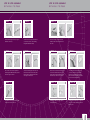
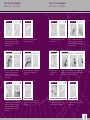
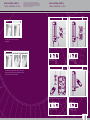
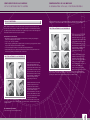
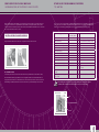
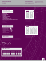
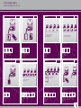
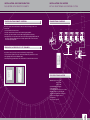
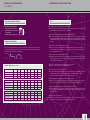
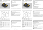
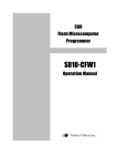
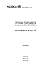
W arrant y & return P oli c y
USER AND INSTALLATION
MANUAL
f o r F M S an d T C S
T ou c h Control M otors , T C S and F M S D e v i c es
1.The Forest Touch Control Motor and Touch Control Devices are warranted against defects of
components and workmanship for three (3) years from the date of purchase from the Forest
Group Nederland B.V. factory. The FMS Devices are warranted against defects of components and
workmanship for five (5) years from the date of purchase from the Forest Group Nederland B.V.
factory.
2. Should any failure to conform with this warranty appear during the specified period under normal
and proper use, and provided that the motor and devices have been properly stored, installed and
maintained with due regard to any directives, instructions and operating procedures provided by the
manufacturer, Forest Group Nederland B.V. shall, upon presentation of proof of purchase, correct
such nonconformity either by repair or by replacement of the nonconforming part, Ex Works, at the
option of Forest Group Nederland B.V. Return of motors or devices pursuant to this paragraph shall be
at purchaser’s risk and expense.
3. Forest Group Nederland B.V. warrants motors and devices, repaired or replaced pursuant to the
foregoing warranties, under normal and proper use, storage, installation and maintenance, against
defects in materials for a period of thirty (30) days from date of start-up of such repaired or replaced
motors or devices or the expiration of the original warranty, whichever is longer.
The foregoing warranties do not cover defects resulting from misuse or failure to follow instructions.
They also do not cover labour on location, service calls, reinstallation or expenses involved in shipping,
packing or returning goods.
In no event shall Forest Group Nederland B.V. be liable for any indirect, incidental, consequential or
other damages in connection with this product. This disclaimer applies both during and after the period
of this warranty.
In no event shall Forest Group Nederland B.V. be responsible for providing working access to the defect,
including disassembly or reassembly of motors, hardware or devices.
R eturn P oli c y
TCS/FMS/MAN-12-2007
Forest Group Nederland B.V. products are customized, and as a rule, they cannot be returned. Any
goods to be returned to the Forest Group Nederland B.V. factory for repair, credit or otherwise must
be clearly marked with the RGA (Return Goods Authorization) number issued by the Forest Group
Nederland B.V. customer service department. No return goods will be accepted unless clearly marked
with an RGA number. Any return shipment to Forest Group Nederland B.V. must be freight prepaid.
All shipments from the Forest Group Nederland B.V. factory will be made EXW, freight collect, best
way, unless arranged otherwise. Final acceptance of returned goods is subject to factory inspection.
Restocking charges will apply.
CONTENT
USER AND INSTALLATION MANUAL
f o r F M S an d T C S
1. Important Instructions TCS Motor 3
2. Instructions for assembling FMS /TCS rail and motor 4
3. Application sheets TCS motor
9
4. Installation and Configuration TCS motor with RF remote/RF switch 12
5. Installation TCS motor with dry contact wall switch 15
6. Installation and Configuration TCS motor with IR remote
17
7. Configuration and programming RS 485 module TCS motor 18
8. Configuration RS 485 module in combination with Crestron/AMX controls
19
9. Configuration Z Wave module in combination with other Z Wave devices
20
10. Other User programming features TCS motor
21
11. Technical information TCS motor
24
12. Application sheets FMS motor
25
13. Installation and configuration FMS motor with RF remote
28
14. Technical information FMS motor
29
15. Frequently asked questions 31
16. Warranty & return Policy
32
I mportant I nstru c tions T C S M otor
Read these instructions carefully before using the TCS Curtain motor and save them for future reference.
This TCS Curtain motor is for indoor use ONLY and may not be installed in humid environments such as bathrooms, showers, etc. This TCS Curtain motor may ONLY be used in combination with the supplied transformer. Transformer specifications: P/N.:ADS-U0241P5.2302, Model: F10452-A, 100-240V~1.2A 50-60Hz. Do not apply reverse power (wrong polarity) to the TCS Curtain motor.
In case the TCS Curtain motor is overheating or smoke comes from the motor, disconnect power
immediately.
If the TCS Curtain motor is connected to the transformer and cannot be operated, disconnect power
immediately and contact your supplier.
Any changes or modifications to the TCS Curtain motor that are not approved by the manufacturer
will void the user’s authority to operate the equipment.
I nstru c tions for assem b lin g F M S / T C S
Necessary items:
FMS Track 5.80 cm or 700 cm
FMS Transport Belt
FMS / CCS Master Carrier Underlap R/L
FMS / CCS Master Carrier Overlap R/L
FMS / CCS Master Carrier Single Arm R/L
FMS / TCS Motor Pulley
FMS / TCS Return Pulley
FMS / TCS Connector
FMS / TCS Metal Clip for motor pulley Articlenumber:
5101001 …
5105501000
5215801000
5215901000
5216001000
5103011000
5103011100
5103011500
5103011001
When the track is to be fitted inside a window frame, make sure to cut off the track by 11 cm, to accommodate for the motor pulley and return pulley.
S T E P BY S T E P A S S E M B L Y
OF THE FMS / TCS TRACK
S tep 1
Slide the belt through the track by using the
FMS belt connector (1).
S tep 3
Take off the cord connector and push the
belt through the FMS Return Pulley (2) until
the above figure is achieved
S tep 5
Now pull the belt throug the track and take
off the belt connector at the end.
S T E P BY S T E P A S S E M B L Y
OF THE FMS / TCS TRACK
S tep 2
Cut the belt under an angle to remove the
1st tooth. This ensures a smooth sliding
through the FMS Return Pulley.
S tep 4
Cut off the remaining part of the 1st tooth,
then attach the belt connector and put the
belt back into the other trackchannel until
above figure is achieved (3).
S tep 6
Now start counting 17 teeth of the belt,
mark the 17th tooth of the belt and cut it
here after.
S tep 7
Now connect one end of the belt to the belt
connector and insert the first piece of the
master carrier into the track. Make sure the
first tooth stays outside of the connector.
S tep 9
Now take the FMS motor pulley apart by
removing the screws.
S tep 8
Connect the other end of the belt to the
connector to make a loop and slide the
master carrier fully into the track. Again
make sure that the first tooth stays outside
of the connector, in the middle.
S tep 1 0
Then position the bottom piece of the motor
pulley onto the track, making sure the belt
falls into place.
S T E P BY S T E P A S S E M B L Y
OF THE FMS / TCS TRACK
S tep 1 1
Now position the center piece onto the
motor pulley, making sure the ball bearing
falls into place, and place the top piece or
the motor pulley again.
S tep 1 3
On the side of the motor pulley; mark the
first visible tooth on the opposite part of
the belt where the first Master Carrier is
attached. Remove the motor pulley again
from the track.
S tep 1 5
On the side of the motor pulley, slide out the
belt, until the marked tooth becomes visible.
Now put the belt connector over this tooth.
It is very important that the marked tooth
will be clamped by the Connector as shown
in the picture.
S T E P BY S T E P A S S E M B L Y
OF THE FMS / TCS TRACK
S tep 1 2
Slide the master carrier to the end of the
track, against the end pulley.
S tep 1 4
Take off the Return Pulley and lift it together
with the belt up onto the track, like the
pictures show.
S tep 1 6
Now position the second master carrier over
the belt connector and slide them together
into the track.
S tep 1 7
S tep 1 8
Now reposition the end pulley onto the track
and fasten the screw.
S tep 1 9
Now tighten all the
screws of the motor
pulley again.
Place the metal FMS clip inside the track,
put the motor pulley on the track again and
place the metal clip over the motor pulley, to
ensure a good fixation.
S tep 2 0
In order to ensure a smooth running of all the components inside the
track, it is necessary to lubricate the track, the pulleys and the master
carriers with the special Forest lubrication spray.
S tep 2 1
Finally position the FMS Carriers onto the
track and click them into the track, by using
your thumbs. Remove the plastic strip.
S tep 2 2
The basic assembly of the track is now
complete, the system is ready to be installed
with the motor.
A ppli c ation s h eets
T o uch C o nt r o l S y stem
In this section Forest presents many different operating possibilities, in detailed
product schedules. Basic installation instructions together with product descriptions
and article numbers are mentioned. All motors have Touch Control and a freewheel
clutch in case of power failure, thanks to which manual operation is possible at all
times. All motors need a 24V DC power adaptor.
A ppli c ation s h eets
T o uch C o nt r o l S y stem
RF CONTROL WITH WALL SWITCH
RF CONTROL WITH REMOTE
S tep 1
1-channel
1-channel
4-channel
4-channel
RF Module
RF Module
First position the motor sideways onto the
motor pulley
TCS motor with RF Receiver and choice of 1- or 4-channel RF remote
control. N.B. it is possible to program two RF transmitting devices on
1 motor.
TCS motor with RF Receiver and choice of 1- or 4-channel RF wall switch.
N.B. it is possible to program two RF transmitting devices on 1 motor.
1x
1x
1x
TCS Motor
RF module RF remote
5201001000 5201001300 1-channel
5201001410
4-channel
5201001400
1x
1x
1x RF wall
TCS Motor
RF module switch
5201001000 5201001300 1-channel:
5201001510
4-channel:
5201001500
S tep 2
INFRARED CONTROL
RF Z-WAVE DOMOTICS
Now twist the motor into the motor pulley so the locking
slide is aligned, and push it into the motor pulley. Now the
motor is ready for set-up and operation.
Z-wave
Module
TCS motor with IR control. By using the IR remote control it is possible
to program different operating settings. Please consult the programming
sheet for further information. N.B. Specific tool for installer only.
TCS motor with Z-WAVE RF application with an RF remote control from
the Z-WAVE Alliance Group. Consult for further details www.z-wave.com
(Options
depend on
domotics
application)
1x
1x
1x IR remote TCS Motor
IR module control
5201001000 5201001200 5201001210
1x
1x
TCS Motor
Z-Wave
5201001000 module
5201001700
1x
Z-Wave
RF remote
control
A ppli c ation s h eets
T o uch C o nt r o l S y stem
PULSE WALL SWITCH
BUILDING AUTOMATION WITH
RS 485 MODULE
AMX / CRESTRON HOTEL AUTOMATION
WITH RS485 AND INDIVIDUAL RF CONTROL
HOTEL AUTOMATION THROUGH RELAY
AND INDIVIDUAL RF CONTROL
pulse-relais
RS 485
PC RS 485
Software
TCS motor with simple wall switch which can be connected through the
dry contact port. Switches with open, close and stop controls are also
possible, by using the switch interface.
TCS motor connected with multiple TCS motors in a building automation
system by using RS485 modules with central operation. Individual control
through building automation system also possible. Motors are interlinked
by using a 4-thread telephone cable with RJ11 connectors.
RF Module
RS 485
serial port AMX Control
(incl.Forest software driver)
Multiple TCS motors in a hotel automation system with AMX or Crestron
operation (download AMX or Crestron software driver). Thanks to RS485
modules possible to control the motors centrally, with AMX / Crestron
panels and / or individually by RF remote control. Motors are interlinked
by using a 4-thread telephone cable with RJ11 connectors
pulse-relais
pulse-relais
Hotel Automation
Pulse-Relay Steering
RF Module
Multiple TCS motors in a hotel automation system through a dry contact
relay. The relays can be interlinked. Individual RF remote control possible,
by using RF receivers and 1- or 4-channel RF remote controls or RF wall
switches.
4 thread
telephone
cable with
RJ11
connector
1x
1x pulse
1x Switch
switch
Interface
TCS Motor
5201001000 5201001520 5201001530
4x
4x
TCS Motor
RS 485
5201001000 module
5201001600
BUILDING AUTOMATION WITH RS 485
MODULE AND INDIVUDUAL RF CONTROL
1x
RS 485
software 5201001620
(Through
installer)
4x
RS485 Cable
(through
installer)
4x
4x
TCS Motor
RS 485
5201001000 module
5201001600
BUILDING AUTOMATION WITH RS 485
MODULE AND INDIVIDUAL PULSE SWITCH
RF Module
RS 485
Multiple TCS motors in a building automation system by using RS485
modules. Central operation and / or individual RF remote control, by
using RF receivers and 1- or 4-channel RF remote controls. Motors are
interlinked by using a 4-thread telephone cable with RJ11 connectors.
4x
RS485 Cable
(through
installer)
1x
RF remote
1-channel:
5201001410
4-channel:
5201001400
pulse-relay
pulse-relay
1x
RS 485
software
5201001620
1x
1x pulse
RS485 Cable switch
(through
5201001520
installer)
TCS motor in tandem application with a master and a slave motor.
Motors connected together with a cable. Control by means of individual
RF receiver and RF remote control or RF wall switch. Aplication under
development.
(Through KNX
installer)
4x
4x
1x
TCS Motor
RF module
RF remote
5201001000 5201001300 1-channel:
5201001410
4-channel:
5201001400
1x Home
1x RF wall
Automation
switch
1 kanaal:
relay
5201001510
4 kanaal:
5201001500
RF Module
Multiple TCS motors in a KNX building automation system through a
KNX interface relay on the dry contact port. The relays can be interlinked.
Choice between central and / or individual KNX control; and / or individual
RF control, by using RF receivers and 1- or 4-channel RF remote controls
or RF wall switches.
4 thread
telephone
cable with
RJ11
connector
4x
4x
1x
TCS Motor
RF module
RF remote
5201001000 5201001300 1-channel:
5201001410
4-channel:
5201001400
pulse-relay
KNX Automation
Pulse-Relais Steering
Multiple TCS motors in a building automation system by using RS485
modules with central operation. Optional individual switch control through
dry contact port. Motors are interlinked by using a 4-thread telephone
cable with RJ11 connectors.
4x
4x
TCS Motor
RS 485
5201001000 module
5201001600
1x RF wall
switch
1 kanaal:
5201001510
4 kanaal:
5201001500
TCS TANDEM APPLICATION
RS 485
SERIAL PORT OF BUILDING
AUTOMATION SYSTEM
4 thread
telephone
cable with
RJ11
connector
4x
4x RS 485
4x
4x
1x RS 485
TCS Motor
module
RF module
RF remote
software
5201001000 5201001600 5201001620 5201001300 1-channel:
5201001410
4-channel:
5201001400
1x
4x
RS 485
RF module
5201001300
software
5201001620
KNX BUILDING AUTOMATION THROUGH
RELAY AND INDIVIDUAL RF CONTROL
pulse-relay
SERIAL PORT OF BUILDING
AUTOMATION SYSTEM
pulse-relais
4x
1x RF wall
KNX relay switch
1 kanaal:
5201001510
4 kanaal:
5201001500
(On request)
2x
1x
1x
TCS Motor
RF module
RF remote
5201001000 5201001300 1-channel:
5201001410
4-channel:
5201001400
1x
Connection
cable tandem
motor
11
I nstallation and Confi g uration
T C S m o t o r with R F r em o te
When a 1-Way RF Receiver Module is connected to the TCS motor by using one of the slots at the front of the
motor, the motor can be operated with the Forest RF remote controls (1 or 4 channel).
I nstallation R F module
Remove one of the slot covers from
the motor and install the RF Receiver
Module in this slot. The slot cover can be
removed with a small screwdriver. Gently
push the RF Receiver in the slot until it is
connected; the front of the RF Receiver
is flush with the front of the TCS motor.
The antenna must be bend downwards
for optimal receiving capabilities. The RF
Receiver Module can be simply removed
by using a small screwdriver.
4-channel RF remote:
Connect the power to the TCS motor. Before the curtain can be operated with the RF remote control, the motor
must be programmed. Choose to which of the 4 channels you want to program the motor and select that
channel on the remote control (you can’t select “all” for programming). Press the configuration button on the
TCS motor twice (notice that the LED comes on every time when the configuration button is pressed, to help
you count the number of times you press this button). After about 3 seconds the LED comes on again. Now you
can program the motor to the remote control by pushing the ”OPEN” or “CLOSE” button shortly. The LED will
go off now the motor is programmed to the selected channel. Use the “OPEN, “CLOSE” and “STOP” buttons
to operate the curtain. It is possible to program a second RF remote control to the motor by following almost
the same procedure again with a different remote. This time, you will need to press the configuration button on
the TCS Motor 4 times (instead of two times). The curtain will now respond to both (different) remote controls.
It is possible to program more than one motor to the same RF remote control and RF frequency, within a
distance of 20 meters between the remote and the receiver.
C h an g in g t h e b atter y of t h e R F R emote c ontrol
To change the battery of the RF remote control, open the cover by
turning it to the left (push it down and to the left at the same time).
Now you have access to the battery compartment. Take the empty
battery out and replace it with a new one. Watch the polarity when you
insert the new battery. Now close the cover again.
Confi g uration R emote
1-channel RF remote:
Connect the power to the TCS motor. Before the curtain can be operated with the RF remote control, the
motor must be programmed. Press the configuration button (with a pen or screwdriver) on the TCS motor
twice (notice that the LED comes on every time when the configuration button is pressed, to help you count the
number of times you press this button).
Battery type: 23A (12V)
Batteries contain chemical substances so they should be disposed of properly, according to local
regulations.
After about 3 seconds the LED comes on again. Now you can program
the motor to the remote control by pushing the ”OPEN” or “CLOSE”
button shortly. The LED will go off, now the motor is programmed.
Use the “OPEN, “CLOSE” and “STOP” buttons to operate the curtain.
It is possible to program a second RF remote control to the motor by
following almost the same procedure again with a different remote. Only
this time the configuration button on the TCS2 motor must be pushed 4
times. The curtain will now respond to both (separate) remote controls.
Led
It is possible to program more than one motor to the same RF remote
control and RF frequency, within a distance of 20 meters between the
remote and the receiver.
13
I nstallation and Confi g uration
T C S m o t o r with R F r em o te
I nstallation of t h e R F W all S wit c h
The mounting plate must be fixed to the wall and then the RF wall switch can be snapped on the mounting plate.
INSTALLATION AND CONFIGURATION TCS MOTOR
W I T H DRY C O N T A C T W A L L S W I T C H
D r y c onta c t W all S wit c h
Any design dry contact wall switch can be connected to the TCS motor as long as it is a double throw,
momentary switch. The switch must be a momentary switch, which means that you only need to push the
switch shortly; the curtain starts moving and the switch will jump back to its neutral (middle) position. The
switch must be connected to the TCS motor with a 3-conductor cable with the following specifications:
Max length
Max AWG
Min AWG
Max mm2
Min mm2
Conductors
Shielding
Core 1-Channel RF Wall Switch (programming similar to RF remote)
This wall switch has 4 buttons and 1 LED. You can operate the curtain by pushing the open and close button.
You can stop the curtain by pushing the stop button. The fourth button has no function on the 1-Channel
remote. It is possible to program more than one motor to the same remote control, within a distance of 20
meters to the receiver.
4-Channel RF Wall Switch (programming similar to RF remote)
This wall switch has 4 buttons and 4 LEDs. First select the channel your curtain is programmed to by pushing
the channel button as many times as needed until the LED of the desired channel comes on (the 4 LEDs in the
centre of the switch). If all 4 LEDs are on, you are in the “ALL”-mode; this means that you will now operate all
curtains programmed to channel 1, 2, 3 and 4 at the same time. You can operate the curtain by pushing the
open and close button and you can stop the curtain by pushing the stop button.
15 meters / 50 feet
20
26
0.5
0.15
3
No
Solid or flexible
S tep 1
Determine the total cable length needed to go from the TCS motor to the wall switch, making sure the cable is
cut a bit longer (safety margin).
S tep 2
Strip the 3 wire ends on one side of the
cable and connect them to the switch
port on the TCS motor (green screw
terminals) as shown, the middle wire
goes to No. 2 on the screw terminal.
It is possible to program more than one motor to the same remote control, within a distance of 20 meters to
the receiver.
CH A N G I N G T H E B A T T E R Y O F T H E R F W A L L S W I T CH
To change the battery of the wall switch,
take the wall switch from the mounting
plate by using a small screwdriver to open
the clip on the side. At the back of the
wall switch you now have access to the
battery. Take the empty battery out and
replace it with a new one. Watch the
polarity when you insert the new battery.
Now click the wall switch back on the
mounting plate.
S tep 3
Route the cable through the cable-guide on the motor as shown, and then to the wall switch.
Battery type: CR2032 (3V)
Batteries contain chemical substances so they should be disposed of properly, according to local regulations.
15
INSTALLATION AND CONFIGURATION TCS MOTOR
W I T H DRY C O N T A C T W A L L S W I T C H
STEP 4
3
1 2
INSTALLATION AND CONFIGURATION
T C S M O T OR W I T H I R R E M O T E
I nfra R ed R e c ei v er M odule
Now the cable must be connected to the
wall switch. This is shown for a standard
wall switch.
Strip the wire ends and connect the wires
to the screw terminals of the switch as
shown in the pictures. The middle wire
is to be connected to pin 3, the other
two connect to pins 1 and 2 (swapping
these two wires will result in a changed
direction of rotation of the motor).
When the IR Receiver Module is connected to the Comm. Port at the bottom of the Touch Control motor, the
motor can be operated and programmed by using a 6-Channel IR Remote control.
INSTALLATION IR RECEIVER MODULE
Plug the IR Receiver Module in the Comm. Port at the bottom of the TCS motor. Position the IR receiver eye in
a location where the eye is visible to the IR remote control.
When another design switch is used, make sure that the middle wire of the 3-conductor cable
(wire 2) is connected to the “neutral” or “common” pin of the switch and that wires 1 and 3 are connected to
the remaining 2 pins (swapping these two wires will result in a changed direction of rotation of the motor).
Note: The arrows on the switch should correspond with the direction in which the curtain moves (open or
close). This can be achieved by turning the entire switch 180 degrees around or swapping the wires on pin 1
and 2.
S tep 5
Connect the power to the TCS motor. Now the curtain can be operated
with the dry contact wall switch. Pushing the switch shortly in one
direction will open the curtain, pushing the switch in the other direction
will close the curtain. Pushing the switch in the opposite direction while
the curtain is moving will stop the motor.
There are also so-called 3-command switches (OPEN, CLOSE and
STOP command) available on the market and for these type of switches
an interface module (see picture) is needed. The interface module is
connected to the switch port of the motor, the same way as described
above. The switch is connected via a RJ11 connector.
CONFIGURATION INFRARED REMOTE
Connect the power to the TCS motor. Before the curtain can be operated with the 6-Channel IR remote control,
the motor must be programmed. Press the configuration button on the TCS motor once (notice that the LED
comes on every time when the configuration button is activated, to help you count the number of times you
press this button). After about 3 seconds the LED comes on again. Now you can program the motor to Channel
1, 2, 3, 4, 5 or 6. You cannot program the motor to the “ALL” Channel. Determine which channel you want to
program the motor to, press the corresponding button on the remote and press the ◀ button or ▶ button. The
LED will go off, now the motor is programmed. Use the arrow buttons (◀ or ▶) to open and close the curtain.
Pressing the opposite direction button while the curtain is moving, will stop the motor. Use the “ALL” buttons
(▲ or ▼) to operate all groups.
Note: instead of using the configuration button on the TCS motor, the “P”-button on the IR remote control can
be used as well. This allows you to program the curtain motor from the ground rather then from a ladder. One
must be careful with programming via the “P”-button on the remote, making sure that only one motor gets in
programming mode at the same time.
17
Confi g uration R S 4 8 5 module
with P C s o ftwa r e f o r T C S m o t o r
R S 4 8 5 proto c ol
Confi g uration R S 4 8 5 module
I N C O M B I N A T I O N W I T H A M X / C R E S T RO N C O N T RO L S
Important: RS 485 from Forest can be used with AMX / Crestron in combination with specific AMX / Crestron
software drivers. Go to the website of AMX or Crestron to download the specific Forest software drivers.
When a RS485 Receiver Module is connected to the TCS motor by using one of the slots at the front of the
motor, the motor can be operated in a RS485 system. RS485 is a definition of an electrical interface standard,
especially designed for hard-wired communication over long distances (up to 1200 m of total cable length). The
functionality of RS485 is defined in the used protocol definition.
The RS485 protocol allows for:
•Main addresses and groups (maximum number is about 200) but no specific sub-groups, although it is
possible to control all groups at the same time;
• “Open”, “close” and “stop” commands;
•Address and group programming with configuration button on the motor (to get in program mode) and then
assign an address through the Home Automation computer;
• Local controls (simple RF and switch) to be disabled/enabled through RS485 protocol;
•An intermediate position to be set (time based), if the TCS motor is aware of its end-positions (this can be
achieved by programming an intermediate position for the motor).
I nstallation R S 4 8 5 module
Remove one of the slot covers from the
motor and install the RS485 receiver
module in this slot. The slot cover can be
removed with a small screwdriver. Gently
push the RS485 Receiver in the slot until
it is connected; the two RJ11 connectors
will stick outside the TCS Motor housing,
facing downwards. The RS485 receiver
module can be simply removed by
gently pulling it out of the slot.
Install the RS485 software on the home
automation computer and connect all
curtain motors (motors must be daisychained) to the serial port of the AMX or
Crestron control. Standard “telephone
cable” and standard RJ11 connectors can
be used for this installation. The
motors can now be operated via this
AMX or Crestron controller, by using the
installed Forest software driver from the AMX or Crestron website. You can operate curtains individually, in
groups of curtains or all curtains at the same time. It is also possible to close or open curtains for only a certain
percentage. The software includes a manual that describes all the possibilities in detail.
Install the RS485 software on the home
automation computer and connect
all curtain motors (motors must be
daisy-chained) to the serial port of this
computer. Standard “telephone
cable” and standard RJ11 connectors can
be used for this installation. The motors
can now be operated via this computer
by using the installed software.
You can operate curtains individually, in groups of curtains or all curtains at the same time. It is also possible
to close or open curtains for only a certain percentage. The software includes a manual that describes all the
possibilities in detail.
PROGRAMING RS485 SOFTWARE:
Contact Forest Group for more detailed information.
19
Confi g uration Z - W a v e module
in c o mbinati o n with o the r Z - W ave d evices
When a Z-Wave RF Transceiver Module is connected to the TCS motor by using one of the slots at the front
of the motor, the motor can be operated with the various Z-Wave control options (remote controls, timers,
computer software) from Z-Wave partners. At this moment, standard Z-Wave RF Modules can be connected to
the com port at the bottom of the TCS motor.
I nstallation Z - W a v e module
Plug the Z-Wave RF transceiver module in the com port at the bottom of the TCS motor.
Programming Z-Wave
Connect the power to the TCS motor. Before the curtain can be operated with one of the Z-Wave controls,
the Z-Wave Module must be programmed. Press the configuration button on the Z-Wave RF Module once
and program a Z-Wave remote (or other Z-Wave device) to the motor. Every Z-Wave control has its own user
manual that gives additional information on how the curtain can be operated with that specific control unit.
O t h er U ser pro g rammin g features
TCS motor
As soon as one or more receiver modules are installed and programmed, there is a possibility to program more
options. This can be done with the configuration button on the TCS motor, or by using the IR receiver module
and IR remote control with programming button. Below you will find all (user) programming options:
Option to be programmed:
Number of times to
press config. button
Type Remark
IR address/channel
1
User
3- or 6-Channel remote control
1-Way RF channel
2
User
1- or 4-Channel Forest remote control
Change direction of rotation
3
User
Toggle function
Additional/second 1-Way RF channel
4
User
1- or 4-Channel Forest remote control
RS485 main address and/or group
5
User
RS485 system required
50 mm fabric release
6
User
100 mm fabric release
7
User
150 mm fabric release
8
User
200 mm fabric release
9
User
Default value
Intermediate position
10
User
Set position
Enable/disable intermediate position
11
User
Toggle function
Switch TouchControl on/off
12
User
Toggle function (Touch Control is on
as default)
TouchControl sensitivity 2 pulses; less
sensitive
13
User
14
User
TouchControl sensitivity 1 pulse;
more sensitive
Return to default value
Before installing the motor and before you start programming the channel and the direction
of rotation, make sure that the lead carrier is halfway to its open or closed position.
Led
Configuration button
Power
21
O t h er U ser pro g rammin g features
TCS motor
Programming the TCS motor is done through the configuration button on the TCS motor or by using the
IR receiver module and IR remote control with programming function. The configuration button is recessed
and can be pushed with a pen or small screwdriver. Notice that the LED comes on every time when the
configuration button is pressed, to help you count the number of times you press this button.
1 Pressing the configuration button once, programs the IR address.
Press the configuration button once, wait for about 3 seconds until the LED comes on, decide which channel
you want to program the motor to, push the corresponding button (1, 2, 3, 4, 5 or 6) on the IR remote
control, then push the ◀ button or ▶ button. The LED will go off, now the motor is programmed to the
selected channel.
2 Pressing the configuration button twice, programs the 1-Way RF address.
Press the configuration button twice, wait for about 3 seconds until the LED comes on, push the “OPEN” or
“CLOSE” button on the RF remote control (1-Channel) or RF wall switch (1-Channel). The LED will go off,
now the motor is programmed to that specific RF remote control or RF wall switch. In case of a 4-Channel RF
remote control or RF wall switch, the desired channel (1, 2, 3 or 4) must be selected before the “OPEN” or
“CLOSE” button is pressed.
3 Pressing the configuration button three times changes the direction of rotation.
If the direction of rotation of the motor needs to be changed, press the configuration button three times and
wait for about 3 seconds until the LED blinks. Now the direction of rotation is changed. The same procedure
must be followed if you want to undo this.
4 Pressing the configuration button four times, programs a second 1-Way RF address.
Press the configuration button four times, wait for about 3 seconds until the LED comes on, push the
“OPEN” or “CLOSE” button on the RF remote control (1-Channel) or RF wall switch (1-Channel). The LED
will go off, now the motor is programmed to that specific RF remote control or RF wall switch. In case of a
4-Channel RF remote control or RF wall switch, the desired channel (1, 2, 3 or 4) must be selected before the
“OPEN” or “CLOSE” button is pressed.
5 Pressing the configuration button five times, programs the RS485 address.
First make sure that the appropriate RS 485 module software is installed on the home automation computer
system and the module is inserted into the motor. Now press the configuration button five times, wait for
about 3 seconds until the LED comes on. In the RS 485 computer program, choose “address program”,
adjust the main address and group address sliders to the desired values and press the “program” button in
the same screen. The LED will go off, now the motor is programmed.
6 Pressing the configuration button six times, programs a curtain relax distance of 50 mm.
A certain curtain relax distance is needed to give the curtain the opportunity to relax, so the fabric is not all
bunched up. By default, the TCS motor will close the curtain 200 mm (8”) after opening. Depending on the
type of fabric and the size of your curtain you may want to change this value. Press the configuration button
six times, wait for about 3 seconds until the LED blinks. Now the curtain relax distance is set to 50 mm (2”).
8 Pressing the configuration button eight times, programs a curtain relax distance of 150 mm.
Press the configuration button eight times, wait for about 3 seconds until the LED blinks. Now the curtain
relax distance is set to 150 mm (6”).
9 Pressing the configuration button nine times, programs a curtain relax distance of 200 mm.
Press the configuration button nine times, wait for about 3 seconds until the LED blinks. Now the curtain
relax distance is set to 200 mm (8”).
10Pressing the configuration button ten times, programs an intermediate position.
To program an intermediate position, press the configuration button ten times, wait for about three seconds
until the LED comes on again. The motor will now automatically go to its open (end) position (curtain is fully
open). Press the “CLOSE” button on the remote control until you reach the desired intermediate position,
then press the configuration button on the TCS Motor one time to confirm this. Press the “CLOSE” button
again and keep it pressed until the fully closed position is reached (motor shuts off automatically). Now
press the configuration button on the TCS Motor one time to confirm this. The motor will now automatically
return to its fully open position and the LED turns off. Now the intermediate position is programmed and the
curtain will stop every time at this intermediate position, whether it is opened or closed.
11Pressing the configuration button eleven times disables/enables the intermediate position.
If you want to disable the intermediate position that is programmed, press the configuration button eleven
times and wait for about 3 seconds until the LED blinks. Now the intermediate position is disabled and the
curtain will no longer stop at this intermediate position. The same procedure must be followed if you want to
re-enable the intermediate position.
12Pressing the configuration button twelve times switches Touch Control off or on.
By default Touch Control is on. Press the configuration button twelve times and wait for about 3 seconds
until the LED blinks. Now Touch Control is switched off. The same procedure must be followed if you want
to switch Touch Control on again.
13Pressing the configuration button thirteen times sets Touch Control less sensitive.
By default Touch Control is set to its highest sensitivity. Should you find this too sensitive in certain
conditions, you can set the sensitivity to a less sensitive level. Press the configuration button thirteen times
and wait for about 3 seconds until the LED blinks. Now Touch Control is set less sensitive.
14Pressing the configuration button fourteen times sets Touch Control more sensitive.
If you want to return to a more sensitive TouchControl setting,press the configuration button fourteen times
and wait for about 3 seconds until the LED blinks; now Touch Control is set to its original setting.
7 Pressing the configuration button seven times, programs a curtain relax distance of 100mm.
Press the configuration button seven times, wait for about 3 seconds until the LED blinks. Now the curtain
relax distance is set to 100 mm (4”).
23
T e c h ni c al information
TCS motor
A ppli c ation s h eets
F o r est M o t o r ise d S y stem
In this section Forest presents many different operating possibilities, in detailed
product schedules. Basic installation instructions together with product descriptions
and article numbers are mentioned. All motors are 220 V AC motors, in 30 W, 45 W
or 60 W versions.
S tep 1
S pe c ifi c ations M otor
• Maximum torque: 1,5 Nm;
• Speed at maximum torque 90rpm;
• No load Current 0,4A;
• Current draw at max. torque 1,5 Nm: 1,05 A;
• Voltage 24 DC with adapter;
• Operational temperature range: 0-50 Cº / 32-122 Fº
• Weight per carrier 1,0 kg - max 10 kg/mtr; straight and curved (two bends of 90 degrees)
• Noise level at 1 mtr distance: <60 Db;
• Speed 15cm/sec;
• CE / FCC and IC approval.
First position the motor sideways onto the
FMS / TCS motor pulley
S pe c ifi c ations T ra c k
S tep 2
• Weight 303 gr/mtr (3.25 ounce/ft);
• Size: 20x20 mm (0.79 x 0.79 inch);
• Aluminium Extrusion 6063 T5, powder coated, lubricated;
• Available lengths 5,80 m and 7,00 m.
Now twist the motor into the motor pulley so the locking
slide is aligned, and push it into the motor pulley. Now the
motor is ready for set-up and operation.
Bendin g / Cur v in g
The motor can be used in a track with one or two bends of 90 degrees. The track can be curved and reversed
curved in any horizontal direction with a radius of 20 cm (8”). Bends with a larger radius and continuous curves
can be made with the electrically powered bending tool.
Min. 55 cm (2110/16“)
30 cm (1Ft.)
L oad ta b le
Min. radius 50 cm (1911/16“)
(with carriers)
Motor
1m
2m
3m
4m
5m
6m
7m
TCS straight
kg
10
20
30
40
50
60
60
TCS 1 bend
kg
10
20
30
40
50
50
50
TCS 2 bends
kg
10
20
30
40
45
45
45
Load table for tandem application available on request.
25
A ppli c ation s h eets
F o r est M o t o r ise d S y stem
RF CONTROL WITH TIMER
RF CONTROL WITH REMOTE
FMS AC Motor
KNX BUILDING AUTOMATION THROUGH
KNX RELAY
RF Z-WAVE DOMOTICS
FMS AC Motor
Hotel/Building Pulse-Relay
Steering Automation
(AMX/Crestron/KNX)
1x RF remote control
4-channel
FMS motor with RF receiver module and 4-channel RF remote control.
Home Automation Pulse-Relay
Steering Z-Wave RF Integrated
1x RF timer
FMS motor with RF Timer, 2 programmable time settings.
FMS motor in Building Management Application (KNX)
FMS motor in a RF Z-WAVE Home Automation network,
with integrated RF relay
(Through
installer)
1x
1x
FMS Motor
RF module
5104011411
230 Volt
5101001030
5101001045
5101001060
1x RF remote
control 4-channel:
5104011401
WALL SWITCH
1x
FMS Motor
230 Volt
5101001030
5101001045
5101001060
1x
1x
RF module
RF timer
5104011410 5104011405
(Somfy
ontvanger)
4x
1x
FMS Motor
KNX Relay
interface
230 Volt
5101001030
5101001045
5101001060
AMX / CRESTRON BUILDING MANAGEMENT SYSTEM
WITH BI-DIRECTIONAL COMMUNICATION FEEDBACK
4x
FMS Motor
230 Volt
5101001030
5101001045
5101001060
DOMOTICS THROUGH HOME
CONTROL BOX
FMS AC Motor
(Through
Z-Wave
integrator)
(Through
Z-Wave
integrator)
4x
RF relay
module
Nieuw nummer
1x
RF Z-WAVE remote
FMS TANDEM APPLICATION
Home Automation Europe
Home Control Box
Hotel/Building Automation
AMX/Crestron
FMS motor with wall switch
FMS motor in AMX / Crestron / etc. with bi-directional position
communication. Optional individual infrared or RF control possible.
FMS motor in a Home Automation Network, with the Home Control Box
from Home Automation Europe
(Through
Home
Automation
Europe)
Datacable
15 cm and
30 cm.
1x
1x FMS wall
switch
FMS Motor
5104001000
230 Volt
5101001030
5101001045
5101001060
4x
1x
FMS Motor
Infrared
receiver
230 Volt
5101001030
5101001045
5101001060
4x
RQ Bus
Controller
1x
Data cable
1x
RQ Bridge
4x
FMS Motor
230 Volt
5101001030
5101001045
5101001060
4x
Home
Control
Box
(Through
Home
Automation
Europe)
1x
RF remote
FMS motor in tandem application with a master and a slave motor. Motors
connected together with a cable. Control by means of individual RF
receiver and RF remote control or RF wall switch.
Aplication under development.
(Through
Home
Automation
Europe)
1x
RF receiver
(On request)
1x
FMS Motor
230 Volt
5101001030
5101001045
5101001060
1x
Tandem
Motor
5101001088
1x
1x
Tandem
RF module
cable
5104011411
5101001888
1x RF remote
control
4-channel:
5104011401
27
I nstallation and c onfi g uration
F M S m o t o r with F o r est R F r em o te
I nstallation F M S motor
with B i Di r ecti o nal B us c o nt r o l s y stem
CONFIGURATION REMOTE CONTROL
Conne c tion S c h edule
In order to program a remote control channel onto the receiver box, the following procedure needs to be executed:
1. Choose a channel on the remote control;
2. Push the “channel” button on the RF receiver box while the signal light blinks;
3. Push the “stop” button on the RF receiver box while the signal light shines continuously;
4. Now push the “up” and “stop” button on the remote control, when the signal light blinks 3 times and
turns off, the channel programming has been successfully completed. If this is not the case, wait 10
seconds and repeat the procedure.
RQ60AUMHG
motor control
RQ60AUMHG
motor control
RQ60AUMHG
motor control
RQ60AUMHG
motor control
RQ60AUMHG
motor control
RR433 V2
Radio Receiver
SP2E2R
AUX
R E M O V I N G A P R E V I O U S L Y S E T CH A N N E L
BUS
BUS
BUS
SP2E2R
RQ Bridge
T24S Dual 433
Transmitter
It is possible to remove a previously set remote control channel, by doing the following:
1. On the receiver box, push both “stop” and “down” button simultaneously and hold for 7 seconds;
2. The signal light on the receiver box will blink 3 times;
3. Now all previously programmed remote control channels have been removed from the receiver box.
RE2S Infrared Eye
OPEN
CLOSE
OPEN
ALL
2 / 14
8 / 20
3 / 15
9 / 21
4 / 16
10 / 22
5 / 17
11 / 23
7 / 19
To RS-232 Input from
Hotel / Building Automation
(AMX / Crestron)
CLOSE
1 / 13
6 / 18
To Optional Input Device
12 / 24
SHIFT
STOP
S pe c ifi c ations M otor
•
•
•
•
•
•
•
•
Maximum torque: 30 W : o,8 Nm
45 W : 1,2 Nm
60 W : 1,6 Nm
Speed at maximum torque 90rpm;
Voltage 230 and 110 V;
Operational temperature range: 0-50 C / 32-122 F
Weight per runner 1,0 kg - max 10 kg/mtr;
straight and curved (two bends of 90 degrees);
Noise level at 1 mtr distance: <60 Db;
Speed 15cm/sec;
CE / FCC and IC approval.
29
T e c h ni c al information
FMS motor
F re q uentl y asked q uestions
S pe c ifi c ations T ra c k
TCS
Q:Can the TCS motor still operate when there is a power failure?
A:Yes, each TCS motor has standard the emergency feature , which means that the motor can still be operated
(by hand) when there is a power failure in house or the building.
• Weight 303 gr/mtr (3.25 ounce/ft);
• Size: 20x20 mm (0.79 x 0.79 inch);
• Aluminium Extrusion 6063 T5, powder coated, lubricated ;
• Available lengths 5,80 m and 7,00 m.
Q:Is the TCS motor compatible with Home and Building Automation systems?
A:Yes , the TCS motor is a modular system. By using the RS485 module or the dry contact input it is compatible
with any Building Automation system. By using the Z Wave module it is compatible with Z Wave enabled
Home Automation systems , and by using the dry contact input any Home Automation relay can connect the
TCS motor.
Bendin g / Cur v in g
The motor can be used in a track with one or two bends of 90 degrees. The track can be curved and reversed
curved in any horizontal direction with a radius of 20 cm (8”). Bends with a larger radius and continuous curves
can be made with the electrically powered bending tool.
Q:How many rails can be controlled with one remote ?
A:With the one channel remote it is possible to control more then one rail. It depends on the user requirement
in the project that you decide. One can choose a 1-channel and 4-channel remote, where a single frequency
can be programmed to multiply motors.
Min. 55 cm (2110/16“)
30 cm (1Ft.)
L oad ta b le
Min. radius 50 cm (1911/16“)
Q:Can you use 1 hard wired switch to control TCS motors at the same time?
A:No, please contact Forest Group for more detailed information.
(with carriers)
Motor
1m
2m
3m
4m
5m
6m
7m
FMS 30W straight
kg
8
16
24
32
40
48
48
FMS 45W straight
kg
10
20
30
40
50
60
60
FMS 60W straight
kg
13
26
39
52
66
80
80
1m
2m
3m
4m
5m
6m
7m
Motor
FMS 30W 1 bend
kg
8
16
24
32
40
40
40
FMS 45W 1 bend
kg
10
20
30
40
50
50
50
FMS 60W 1 bend
kg
13
26
39
52
66
66
66
1m
2m
3m
4m
5m
6m
7m
Motor
Q:Is it possible to connect more then 1 motor in a system?
A:Yes that is no problem. Via de RS485 module and a standard 4 thread phone data cable, motors can be
connected and addressed individually or by group. It is possible to connect up to 200 motors at the same
time, by using the RS485 modules.
FMS 30W 2 bends
kg
8
16
24
32
36
36
36
FMS 45W 2 bends
kg
10
20
30
40
45
45
45
FMS 60W 2 bends
kg
13
26
39
52
60
60
60
Q:Is it possible to choose optional for Touch Control?
A:Yes, by programming with the configuration button or using the IR remote for programming you can decide
to switch off or turn on the touch control. Standard the touch control is always activated. You can also
influence the sensitivity of the touch control by the programming procedure.
Q:How many kilogrammes can the TCS motor handle : straight and curved?
A:In general you can calculate with the existing glider on the CS rail with 10 kg per meter/glider for straight
rails. For curved rails it will be lower. See page 25 and 31 on the manual for exact weight figures.
Q: What is the difference between Radio Frequency Control and Infra red control?
A: The easiest analogy to make concerning user operation is that radio frequency is like a garage door operator,
where you don’t point the transmitter; while infra red is like a TV, where you point the transmitter at the
device to be controlled.
Q: Can the curtain be stopped by hand
A: No This is not possible, as the motor needs a regulated force to operate. If it would be possible to stop the
curtain by hand, the motor would not be able to pull larger/heavier curtains.
Load table for tandem application available on request.
31