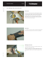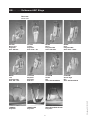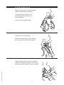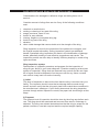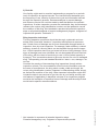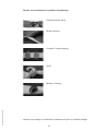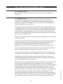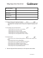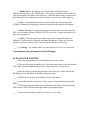
1
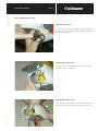
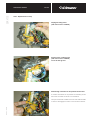
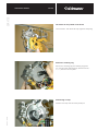
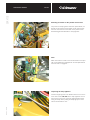
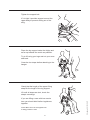
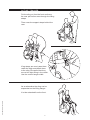
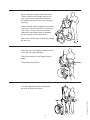
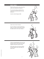
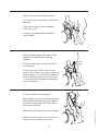
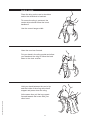
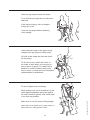
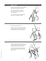
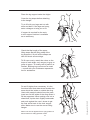
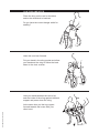
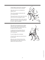
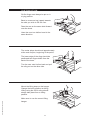
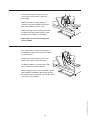
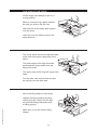
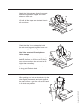
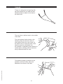
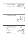
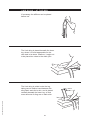
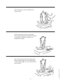
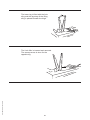
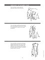
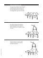
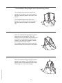
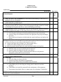
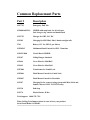
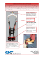
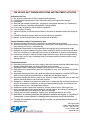
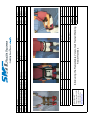
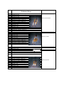
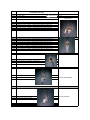
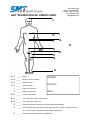
Ceiling Lift
User Manual
For Technical Support
Call
SMT HEALTH SYSTEMS
1380 Legion Rd
Detroit Lakes, MN 56501
1-800-725-7761
Ask for “Ceiling Lift Tech Support”
Or
Call your local SMT Representative
www.smths.com
© Guldmann · 1071/07/06· SIDE 75
SERVICE
GH2 Service manual
GH2 – Service manual
7.01.00
SERVICE
GH2 Service manual
7.01.01
GH2 – Demounting of covers
Opening of end cover
To open the end cover, press against the grooved marks
as shown in the illustration and pull outwards. It might be
necessary to press hard.
Demounting of side cover
Tip up the end covers and loosen two setscrews in each
end with a 3 mm / 1/8’’ Allen key.
Demounting of side covers
© Guldmann · 1071/07/06· SIDE 76
Move the side covers slightly apart from one another and
demount the end covers. Then demount the side covers
SERVICE
GH2 Service manual
7.01.02
GH2 – Replacement of batteries
Demounting of batteries
Turn the yellow battery lock anti-clockwise and demount the
batteries.
Demounting of battery connections
Remove the female push-on terminals from the batteries.
Note the position of wires and polarity of connections.
Mounting of new batteries
© Guldmann · 1071/07/06· SIDE 77
Mount the batteries in reverse order of the demounting.
The wires of the lower battery MUST be placed in the gap
in order not to be jammed.
SERVICE
GH2 Service manual
7.01.03
Positioning of batteries
© Guldmann · 1071/07/06· SIDE 78
Position the poles of the batteries as illustrated.
ALWAYS BE SURE that polarity is as shown in the
illustration.
Check that the wires are placed in the gap without
being jammed between battery and chassis.
SERVICE
GH2 Service manual
7.01.04
GH2 – Replacement of strap
Unplug the lifting motor
(and drive motor if installed)
Pull the wires of lifting motor
(and drive motor if installed)
out of the wire groove
Demounting of bracket for the printed circuit board
To release the bracket for the printed circuit board, pull the
front hook outwards as shown in the illustration.
© Guldmann · 1071/07/06· SIDE 79
Then pull the bracket towards the front hook and outwards
in order to disengage the hooks at the end of the bracket.
SERVICE
GH2 Service manual
7.01.05
Tilt bracket for the printed circuit board
Tilt the bracket. Then demount strap tightener and spring.
Removal of retaining ring
Remove the retaining ring with retaining ring pliers
(no. 2 for the outer retaining rings, diameter 26 mm /
1 1/16’’). Demount the reel plate.
Demounting of strap
© Guldmann · 1071/07/06· SIDE 80
Demount the strap with sole and cylinder pin.
SERVICE
GH2 Service manual
7.01.06
Mounting of new strap
IMPORTANT: The strap MUST be mounted as shown in
the illustration.
Be sure to position the plane surface of contact anticlockwise (i.e. against the pulling direction); then secure the
strap with the original cylinder pin.
The length of the folded part of the strap should be 100
mm / 4’’.
Mount the strap as shown in the previous illustration.
Mounting of strap tightener
Reinstall reel plate and retaining ring CAREFULLY.
Mount spring and strap tightener.
The strap tightener should be positioned UNDERNEATH
the strap. If necessary, lift the strap with the 3 mm / 1/8’’
Allen key when mounting the strap tightener.
Push down strap tightener
© Guldmann · 1071/07/06· SIDE 81
Before mounting bracket for the printed circuit board, push
the strap tightener slightly down as shown in the illustration. If necessary, the 3 mm / 1/8’’ Allen key can be used as
leverage by placing it above the strap tightener and below
the emergency stop switch.
SERVICE
GH2 Service manual
7.01.07
Mounting of bracket for the printed circuit board
Only when the strap tightener has been pulled down, the
bracket for the printed circuit board can be mounted without the micro switch on the back of the printed circuit
board being jammed behind the strap tightener.
Note:
Make sure that the hooks at the end of bracket of the printed circuit board have engaged with the side plate before
the front hook is engaged.
Inspecting the strap tightener
© Guldmann · 1071/07/06· SIDE 82
Check through spyhole in the bracket that the lever of the
micro switch rests ON TOP of the strap tightener. Check
the function of the micro switch by tightening and slackening the strap. When pulling the strap lightly the micro
switch should make a click.
SERVICE
GH2 Service manual
7.01.08
GH2 – Replacement of the hand control
Demounting of hand control
Unscrew fork terminal and remove it from the emergency
stop switch, and remove the 6-way connector from the
printed circuit board.
Disengage the hook of the wire suspension and push the
wire suspension sideways out of the chassis.
Wire suspension
The route of the wire through the labyrinth of the wire
suspension.
© Guldmann · 1071/07/06· SIDE 83
Mounting of wire suspension
IMPORTANT! Make sure that the chassis does not cut into
the wire when mounting the wire suspension.
Press the wire into position in the track, before
CAREFULLY pushing the wire suspension into position.
Check that the hook is engaged behind the chassis. Insert
the 6-way connector into the printed circuit board.
SERVICE
GH2 Service manual
7.01.09
GH2 – Mounting of side covers and end covers
Side covers
Position the side covers with the lobes facing the receptacles on the chassis. Make sure that the tension pieces are
located behind the lobes. Check that wires are not being
jammed. Make sure that the wire of the power intake is
positioned correctly in the opening on top of the chassis.
When both side covers have been mounted, tighten setscrews in the tension pieces lightly.
End covers
It is possible to mount the end covers after having mounted
the side covers because the end covers are very flexible.
© Guldmann · 1071/07/06· SIDE 84
Mounting of end cover
Fit the end cover into the slot on one side by means of the
hinge in the corner of the cover.
Position the end cover at an angle of approximately 45º, as
shown in the illustration, in order to ensure that the hinge
in the opposite corner of the cover faces the groove in the
slot.
© Guldmann · 1071/07/06· SIDE 85
SERVICE
GH2 Service manual
7.01.10
Bend the end cover and fit it into the slot on the
other side through the groove.
© Guldmann · 1071/07/06· SIDE 86
SERVICE
Main inspection of GH2, GH2 HD
and rail system
7.02.00
Performance testing GH2 ang GH2 HD
• The performance test provides a first-hand impression
of the status of the entire system. A note is made of any
instances of non-compliance which are subsequently
investigated further during the main inspection.
• The hoist is run through the entire system by the technician, who makes a general observation of the system
while all system functions are tested.
• Testing of up/down function.
• Testing of drive motor, if any.
• Checking of any undesired noises from the wheels.
• Checking of any undesired noises from the gears/motor.
• Testing of Combi-lock, switch tracks and turntables, if
any.
Main inspection GH2 and GH2 HD
• Remove covers and follow the procedure below, if
necessary together with the electrical functional description for GH2 ang GH2 HD.
• Check transformer min. 24 V AC
• Check voltage from the transformer to the charging
station, including any room-covering charging station,
thereby ensuring that the cable connections are correct.
• Check batteries:
Measure battery voltage on both batteries without load.
It must be above 12.0V and the difference between the
two batteries must be max. 0.3V. Now measure the voltage with load (60-80 kg/132-176lbs). The rate of speed
at which the voltage drops must be the same on both
batteries, and the difference between the two batteries
must be max. 0.3V.
• Check emergency stop and emergency lowering function with a load corresponding to 85 kg/187lbs.
• Check endstop down – first without load on the lifting
strap. It should not be possible to lower. Then test with
the weight of the lifting hanger on the strap. It should
now be possible to lower.
• Check endstop up. Run lifting strap all the way up and
against the stop. This should cause the micro switch to
stop the lifting function immediately. The same should
apply when the strap is at an angle of more than 45º
relative to the hoist lengthways and 10º crossways.
• Check lifting strap for correct installation and check
for cut threads. If the edges of the strap are very worn
due to swings or if there are any other signs of wear,
the strap should be replaced. Also check the hoist to
identify any sharp edges or burrs. Any defects must
be repaired before fitting of the new strap. Follow the
instructions on the fitting of lifting straps.
• Check trolley – as regards the fitting of the trolley to the
hoist, locking rings must be fitted at either end of the
axle which holds the trolley.
• Check coating if the hoist is coated. It must be ensured
that the coating remains functional. If not, the hoist must
be recoated using Silicone Spray – Sil Slip A.
• Fit covers.
• Carry out performance test of the entire system with
rated load.
Rail system in general
• Carry out a performance test of the entire system with
rated load.
• Check that the system is completely level.
• Check the bracket to ensure it has been correctly
tightened.
• Check rail connections to ensure correct positioning
of cylinder pins and rail connectors.
• Retighten all endstops and check for installing safety
split pin.
• The rail system should be marked with the maximum
load, cf. the distance between the fittings.
Combi-locks
• Function test, including checking the diode function on
the manual control.
• Check transformer, 24 volt AC.
• Check attachment to rail (remove covers).
• Check that the tongue does not subject the safety lock
on the traverse rail to a maximum load – the safety lock
must not fully open. If this is the case, the combi-lock
must be adjusted.
• Both safety locks must be checked manually and electronically – must return normally without problems.
Switch track manual/electrical
• Function testing.
• Check transformer 24 V AC.
Turntable
• Function testing.
• Check transformer 24 V AC.
• Check endstop function – the turntable rail must be
completely in line with rails on either side of the turntable. If this is not the case, the rail system must be
adjusted, and if the turntable turns too much, the cover
plates must be removed and the end stop adjusted.
GB/US . . . . Guldmann ABC Slings
GB . . . . . . . Guldmann ABC Slings
ACTIVE
Micro Plus
Polyester
Size: XS-XXL
ACTIVE
Trainer
Polyester
Size: Kids – XL
BASIC
Basic
Polyester/Net
Size: Kids-XXL
BASIC
High
Polyester/Net
Size: Kids – XXXL
BASIC
Low
Polyester/Net
Size: XS – XXL
CUSTOM
Amputee
Polyester
Size: S-L
CUSTOM
Sit-On
Net
Size: Standard/Wide
CUSTOM
Sit-On High
Net
Size: Standard/Wide
TURNER
Polyester
LIMB SLING
Polyester
REPOSITIONING SLING
Polyester
© Guldmann GB-1005/06/07
Item nos:
xxxxx-xxx
C ontents
© Guldmann GB-1005/06/07
Active Micro Plus. . . . . . . . . . . . . . . . . . . . . . . . . . . . . . . . . . . . . . . . . . . . . . . . . . . . . . . . . . . . 5
Active Trainer . . . . . . . . . . . . . . . . . . . . . . . . . . . . . . . . . . . . . . . . . . . . . . . . . . . . . . . . . . . . . . 7
Basic Basic. . . . . . . . . . . . . . . . . . . . . . . . . . . . . . . . . . . . . . . . . . . . . . . . . . . . . . . . . . . . . . . . 9
Basic High. . . . . . . . . . . . . . . . . . . . . . . . . . . . . . . . . . . . . . . . . . . . . . . . . . . . . . . . . . . . . . . . . 11
Basic Low . . . . . . . . . . . . . . . . . . . . . . . . . . . . . . . . . . . . . . . . . . . . . . . . . . . . . . . . . . . . . . . . 13
Custom Amputee. . . . . . . . . . . . . . . . . . . . . . . . . . . . . . . . . . . . . . . . . . . . . . . . . . . . . . . . . . . 15
Custom Sit-On. . . . . . . . . . . . . . . . . . . . . . . . . . . . . . . . . . . . . . . . . . . . . . . . . . . . . . . . . . . . . 17
Custom Sit-On High . . . . . . . . . . . . . . . . . . . . . . . . . . . . . . . . . . . . . . . . . . . . . . . . . . . . . . . . 19
Turner . . . . . . . . . . . . . . . . . . . . . . . . . . . . . . . . . . . . . . . . . . . . . . . . . . . . . . . . . . . . . . . . . . . 21
Limb sling – at the bed. . . . . . . . . . . . . . . . . . . . . . . . . . . . . . . . . . . . . . . . . . . . . . . . . . . . . . 23
Limb sling – at the wheel chair. . . . . . . . . . . . . . . . . . . . . . . . . . . . . . . . . . . . . . . . . . . . . . . . 26
Repositioning sling . . . . . . . . . . . . . . . . . . . . . . . . . . . . . . . . . . . . . . . . . . . . . . . . . . . . . . . . . 27
Repositioning sling – use of different lifting hangers when repositioning patients. . . . . . . . . 29
Laundering recommendation. . . . . . . . . . . . . . . . . . . . . . . . . . . . . . . . . . . . . . . . . . . . . . . . . . 30
Sling inspection checklist . . . . . . . . . . . . . . . . . . . . . . . . . . . . . . . . . . . . . . . . . . . . . . . . . . . . 30
Safe Operating Practices with Slings . . . . . . . . . . . . . . . . . . . . . . . . . . . . . . . . . . . . . . . . . . . 31
WARRANTIES. . . . . . . . . . . . . . . . . . . . . . . . . . . . . . . . . . . . . . . . . . . . . . . . . . . . . . . . . . . . . 34
© Guldmann GB-1005/06/07
A ctive M icro P lus
Place the sling on the user’s shoulders
and/or the wheelchair’s backrest.
To ensure sling is centered, the
center stripe should follow the
user’s backbone.
Use the correct hanger width.
Have the user lean forward.
Position the upper edge of the sling at
the lower edge of the shoulder blade.
© Guldmann GB-1005/06/07
Pass the upper straps under the armpits.
However, not higher up than a minimum of
two finger widths between sling and armpit.
Tighten the support belt.
If it is tight it provides support around the
upper body to prevent sliding out of the
sling.
Place the leg support under the thighs and
as far up towards the crotch as possible.
Try to lift using your legs and not your arms
and back.
Cross the les straps before attaching to the
hanger.
Check that the length of the upper lifting
strap fits the length of the leg support.
If you are lifting a user with low muscle
tone you should hold his/her legs/knees
together.
Active Micro Plus can be applied from
a sitting position in bed.
© Guldmann GB-1005/06/07
Lift until all straps are taut, check the
straps’ mountings.
A ctive T rainer
Put the sling on from the front and have
the user put his/her arms through the lifting
straps.
Then cross the support straps behind the
user.
If leg straps are used, pass them
under the thigh and attach them
to the sling. Be careful that they
are not too tight fitting in the crotch.
Use the correct hanger width.
As an alternative the sling can be
suspended on the lifting hanger.
© Guldmann GB-1005/06/07
It is then attached from the front.
When using the hanger (bar) with Active
Trainer, position the hanger (bar) to the
rear of the user’s head while attaching
the straps and prior to the user coming to
standing.
Check that the support straps are correctly
tensioned. There should be no more than
max 15 cm / 6 inch space at the back
where the rear straps cross in between
the two halves of the trainer sling.
Make sure that the size of the lifting hanger
fits the user.
Have the user lean slightly forward and lift
a bit until the strap stretches.
Check the tension of the support straps’
again.
Then start the actual lift
© Guldmann GB-1005/06/07
You must not lift to such a height that
the user is lifted off the floor.
B asic B asic
Place the sling on the user’s shoulders
and/or the wheelchair’s backrest.
To ensure the sling is centered, the
center stripe should follow the user’s
backbone.
Use the correct hanger width.
Have the user lean forward.
Put your hand in the sling pocket and
allow your hand and the sling to follow
the back down to the chair cushion.
Hold your hand between the user’s hip
and the inside of the sling at the back
support and press down the sling.
© Guldmann GB-1005/06/07
At the same time pull the leg support
forward towards the knees with your
other hand.
Place the leg support under the thighs.
Try to lift with your legs and not with arms
and back.
If the legs are heavy, ask a colleague
to help you to lift.
Cross the leg straps before attaching
to the hanger.
Check that the length of the upper lifting
straps fits the lifting strap of the leg
supports.
Lift until all the straps are taut and check
all mountings.
To lift user evenly, match colors on the
loops of each strap, such as grey to grey or
green to green. To modify user’s position or
comfort, differing loop colors can be used
– consult with your Guldmann representative for assistance.
Do not lift higher than necessary.
Make sure to use the correct lifting hanger.
Basic Basic can be applied from a lying position
in bed as well as a sitting position in bed.
10
© Guldmann GB-1005/06/07
When putting user into a wheelchair, tip the
chair slightly backwards and push against
the user’s knees to get user as far back in
the chair as possible.
B asic H igh
Place the sling on the user’s shoulders
and/or the wheelchair’s backrest.
To ensure the sling is centered, the
center stripe should follow the user’s
backbone.
Use the correct hanger width.
Have the user lean forward.
Put your hand in the sling pocket and allow
your hand and the sling to follow the back
down to the chair cushion.
Hold your hand between the user’s hip
and the inside of the sling at the back
support and press down the sling.
© Guldmann GB-1005/06/07
At the same time pull the leg support
forward towards the knees with your
other hand.
11
Place the leg support under the thighs.
Try to lift with your legs and not with arms
and back.
If the legs are heavy, ask a colleague
to help you to lift.
Cross the leg straps before attaching
to the hanger.
Check that the length of the upper lifting
straps fits the leg support’s lifting strap.
Lift until all the straps are taut and check
all mountings.
To lift user evenly, match the colors on
the loops of each strap, such as grey to
grey or green to green. To modify user’s
position or comfort, differing loop colors
can be used – consult with your Guldmann
representative for assistance.
Do not lift higher than necessary.
Make sure to use the correct lifting hanger.
Basic High can be applied from a lying position in
bed as well as a sitting position in bed.
12
© Guldmann GB-1005/06/07
When putting user into a wheelchair, tip the
chair slightly backwards and push against
the user’s knees to get the user as far back
in the chair as possible.
B asic L ow
Place the sling on the user’s shoulders
and/or the wheelchair’s backrest.
To ensure the sling is centered,
the center stripe should follow the
user’s backbone.
If you have the correct hanger width,
put arms, for example, outside.
Have the user lean forward.
Put your hand in the sling pocket and
allow your hand and the sling to follow
the back down to the chair cushion.
Hold your hand between the user’s hip
and the inside of the sling at the back
support and press down the sling.
© Guldmann GB-1005/06/07
At the same time pull the leg support
forward towards the knees with your
other hand.
13
Place the leg support under the thighs.
Cross the leg straps before attaching
to the hanger.
Try to lift with your legs and not with
arms and back. If the legs are heavy,
ask a colleague to help you to lift.
If support is required for the neck,
a neck support cushion is available
as an accessory.
Check that the length of the upper
lifting straps fits the lifting strap of the
leg supports. Lift until all the straps are
taut and check all mountings.
Do not lift higher than necessary. It is the
functional level that determines whether the
arms should be inside or outside the sling.
Users with paralysis should have the paralyzed arm on the inside of the sling where it
will be supported. When putting user into a
wheelchair, tip the chair slightly backwards
and push against the user’s knees to get
the user as far back in the chair as possible. Make sure to use the correct lifting
hanger.
Basic Low can be applied from a lying position in
bed as well as a sitting position in bed.
14
© Guldmann GB-1005/06/07
To lift user evenly, match the colors on the
loops of each strap, such as grey to grey or
green to green. To modify user’s position or
comfort, differing loop colors can be used
– consult with your Guldmann representative for assistance.
C ustom A mputee
Place the sling on the user’s shoulders
and/or the wheelchair’s backrest.
Do you have the correct hanger width for
stability?
Have the user lean forward.
Put your hand in the sling pocket and allow
your hand and the sling to follow the back
down to the chair cushion.
Hold your hand between the user’s hip
and the inside of the sling against the back
support and press down the sling.
© Guldmann GB-1005/06/07
At the same time pull the leg support
forward towards the knees with your
other hand.
15
Always begin by placing the leg support
on the side that the stump is shortest.
Have the user lean over towards the
opposite side.
Place the leg support underneath with
your hand held flat.
Then get the user to lean over to the other
side and pull the leg support forward.
Repeat the process with the other leg support, which should be layered underneath
the first or upper leg support.
When both the leg supports are in place
under the user, put the top one through
the inner strap guide and the bottom one
through the outer strap guide.
It means that the leg support that you
started with will always go though the
inner strap guide.
Do not lift higher than necessary.
Lift until all the straps are taut and check
all mountings.
16
© Guldmann GB-1005/06/07
When the user is lifted, he/she will be
tilted backwards for safety reasons and
appropriate weight distribution
C ustom S it- O n
Sit-On slings must always be put on in
a lying position.
Bend or cross one leg (upper) towards
the side you wish to roll the user.
Pass the arm on the same side forward
over the chest.
Have the user turn his/her head in the
same direction.
The center stripe should end approximately
at the end of spine, beginning of the pelvis.
The lower edge of the sling should be
positioned two finger-widths from the
back of the knee.
Turn the user onto his/her back and pull
the sling out on the other side.
© Guldmann GB-1005/06/07
Mount the lifting strap on the hanger.
Change the bed’s position to sitting.
Lifting using the Sit-On sling should
always take place from a sitting
position.
Make sure to use the correct lifting
hanger.
17
Lift until all straps are taut, but user
is still sitting on the bed. Check all
mountings.
Attach the Velcro straps that will
connect and hold together the upper
and lower straps on each side.
Check that the Velcro straps that hold
the back and leg parts together have
not become caught in the hanger.
Note! You must not lift using these
Velcro straps
It is a good idea to lower the height of
the bed first, whenever possible, before
you lift the user.
It feels more secure and you do not
need to lift higher than necessary.
Do these stages in reverse when the
user is being put back into bed.
18
© Guldmann GB-1005/06/07
When putting user into a wheelchair, tip the
chair slightly backwards and push against
the users knees to get the user as far back
in the chair as possible.
C ustom S it- O n H igh
Sit-On slings must always be put on in
a lying position.
Bend or cross one leg (upper) towards
the side you wish to roll the user.
Pass the arm on the same side forward
over the chest.
Have the user turn his/her head in the
same direction.
The center stripe should end approximately
at the end of the spine, beginning of the
pelvis.
The lower edge of the sling should be
positioned two finger-widths from the
back of the knee.
The upper edge of the sling will support the
head.
Turn the user onto his/her back and pull
the sling out on the other side.
Mount the lifting strap on the hanger.
© Guldmann GB-1005/06/07
Change the bed’s position to sitting.
Lifting using the Custom Sit-On High
sling should always take place from
a sitting position.
Make sure to use the correct lifting
hanger.
19
Attach the Velcro straps that will connect
and hold together the upper and lower
straps on each side.
Lift until all the straps are taut and check
all mountings.
Check that the Velcro straps that hold
the back and leg parts together have not
become caught in the hanger.
Note! You must not lift using these
Velcro straps
It is a good idea to lower the height of the
bed first, before you lift the user. It feels
more secure and you do not need to lift
higher than necessary.
Do these stages in reverse when the user
is being put back into bed.
20
© Guldmann GB-1005/06/07
When putting user into a wheelchair, tip the
chair slightly backwards and push against
the users knees to get the user as far back
in the chair as possible.
T urner
Turner is a triangular turning sling with
two lifting straps on one side and one
fastening strap to attach to the bed on
the other side.
The user lies on his/her back in the middle
of the bed.
The carer places his/her hand on the
fastening strap for the bed, which is
now passed under the user’s back, at
the same time as using the palm of the
hand to press the sling down into
the mattress, compressing the mattress to
create space, allowing carer’s hand and
sling to pass beneath the user.
© Guldmann GB-1005/06/07
The fastening strap is pulled as far as
possible out on the other side to be
attached to the frame of the bed.
21
The user is now put in a preparatory
position for one sided turning.
The user’s arms are put on his/her
chest and legs are crossed.
The sling’s lifting strap is now mounted
onto the hanger in a ceiling or floor lift.
The lift is now activated while the carer
supports the user’s shoulders and hips.
This will improve the user’s comfort while
turning.
It is a good idea to support the user’s
head with a pillow.
The user is now turned to the other side.
22
© Guldmann GB-1005/06/07
Do not operate the hanger higher up
than necessary.
L imb sling – at the be d
If necessary the stiffener can be placed
before use
The Limb sling is placed beneath the lower
leg, where it is most appropriate for the
care task to be done. However, it ought not
to be placed too close to the ankle joint.
© Guldmann GB-1005/06/07
The Limb sling is pulled under the leg,
taking care to keep a hand between the
sling fabric and user’s skin, and is placed
centrally beneath the lower leg, so that
even amounts of sling are on each side.
23
The Limb sling is now mounted to the
lifting hanger.
If the Limb sling is used in connection
with personal hygiene for bariatric patients,
it can also be used as assistance to
separate the thighs.
24
© Guldmann GB-1005/06/07
The Limb sling can also be utilized when
fitting a lifting sling if the user has heavy
or very heavy thighs or very compromised
skin integrity.
The lower leg is lifted with the limb
sling and the leg strap of the lifting
sling is placed beneath the thigh.
© Guldmann GB-1005/06/07
The Limb lifter is lowered and removed.
The same process is done for the
opposite leg.
25
L imb sling – at the wheel chair
The Limb lifter is lead under the
thigh at the back of the knee joint.
The Limb lifter is pulled through, taking
care not to shear the user’s skin, so that
it is centralized in relation to the thigh
lengthwise.
26
© Guldmann GB-1005/06/07
The Limb lifter is mounted to the lifting
hanger and the thigh can now be lifted
slightly from the seat. The sling’s limb
strap can now be placed either beneath
the user’s thigh or be drawn out without
putting strain on the skin.
R epositioning sling
The repo sling is placed under the patient
centralized at the mattress and so that
the top of the sling is in line with the
top of the patient’s head. It is fine with
exceeding textile higher than the head.
By rolling the patient he is placed in
the position prepared for side-lying
and as a general rule the strap no 2
and 3 (counted from the patient’s head)
are used.
© Guldmann GB-1005/06/07
When the patient has been “rolled”
to side-lying place relevant pillows
to support the patient.
27
28
© Guldmann GB-1005/06/07
Hereafter the straps are removed from
the lifting hanger.
Repositioning sling .
– use of different lifting hangers when repositioning patients
The 2 straps nearest to the head of the
patient are mounted in the cross hanger’s
two lifting hooks closest to the head of the
patient.
The 2 straps closest to the feet of the
patient are mounted to the cross hanger’s
two lifting hooks closest to the patient’s
feet.
When the standard lifting hanger is placed
perpendicular to the patient. The 3 (6)
straps closest to the head of the patient are
mounted in the hangers two lifting hooks
closest to the head of the patient. Always
mount the head straps at last.
The 2 bottom straps are placed at the two
hooks furthest from the head of the patient.
© Guldmann GB-1005/06/07
When the standard lifting hanger is placed
parallel to the patient. The straps are now
placed similar to first drawing on this page
illustrating use of the cross hanger.
29
L aun d ering recommen d ation
85°
S ling inspection checklist
Before using a Guldmann sling / accessory check the following*:
Is the sling clean?
Follow facility specific infection control and laundering procedures
Is the sling’s label present, legible and complete?
Missing, illegible or incomplete sling label(s) could compromise identification
of appropriate size of the sling, function of sling, and or weight limit capacity of
the sling
Are the lifting straps and stitches intact?
Look for broken or worn stitches
Look for knots in straps
Look for tears or fraying of straps
Look for snags or punctures or holes
Look for any particles in fabric of straps
Is the fabric intact?
Look for abnormal wear patterns, excessive wear, abrasive evidence
Look for cuts or frayed fabric
Look for unusual or significant discoloration
Look for snags, punctures, tears, holes
Look for frayed or insecure seams
Look for any acid / caustic / thermal burns
Look for changes in material consistency, e.g. increased stiffness
Look for any imbedded particles
*
Not intended to represent all potential inspection steps.
Potential damage may vary. Judgment of inspector/site prevails.
30
© Guldmann GB-1005/06/07
Are slings the original size and length without the use of knots, pins,
tape or other methods to change the shape, shorten or lengthen them?
S a f e O perating P ractices with S lings
Considerations for damaged or defective slings and taking them out of
service*:
Consider removal of slings from service if any of the following conditions
exist:
1 .
.
3 .
4 .
5 .
6 .
7 .
.
chemical or caustic burns
melting or charring of any part of the sling
snags, punctures, tears or cuts
broken or worn stitches
missing, illegible or incomplete sling tag
knots in any part of the sling
abrasion
other visible damage that causes doubt as to the strength of the sling
Sling inspection is done for the protection of the patient, the caregiver, and
the overall hospital site safety. A sling inspection system has additional
benefit. Systematic sling inspection will assist in the identification of damage
trends, potentially leading to cost effective suggestions and results. The
inspection process can also help to identify inventory duplicity in certain sling
types and sizes.
Sling inspection system
Development of a specific procedure and program for the inspection of
slings at your facility is your best safeguard. Consider employing a three part
system of inspection. Slings that are removed from service and are not capable of repair should be disposed of so they are unfit for any future use and
can not find a way back into active inventory.
1) Initial
This level of inspection is done at the time that the sling is received into your
facility. The inspector should insure that no damage has occurred during
transit, and also verify that the sling work load limits match those contained in
the manufacturer’s catalogue. If your facility documents the sling inspection
process through written inspection records, the paper trail should begin at this
stage
© Guldmann GB-1005/06/07
2) Frequent
The frequent level of inspection should be done by the sling user before each
use. The sling should be examined and removed from service if damage is
detected. The sling user should also determine that the sling is proper for the
patient conditions, care task required and the required weight capacity.
31
3) Periodic
Your facility might want to consider implementing a program for a periodic
level of inspection at regular intervals. The interval should be based upon
the frequency of use, severity of the service cycle and information derived
through the inspection process. Recommendations to prevent damage
and enhance service life could be made by staff that perform the periodic
inspections. If written inspection records are maintained, they should always
reference the unique sling identification number, and be updated to record
the condition of the sling. Not intended to represent all potential inspection
steps or all potential aspects of product management program. Judgment of
inspector/site prevails. Guldmann ™
*
Not intended to represent all potential inspection steps.
Potential damagemay vary. Judgment of inspector/site prevails.
32
© Guldmann GB-1005/06/07
Sling inspection technique*
The sling inspection procedure should be thorough, systematic and consistent; both visual and “hands on” inspection techniques are recommended. Certain forms of damage are far more discernable through hands-on
inspection, than by visual inspection. For example, fabric stiffness, crushed
webbing, as well as, thinning fabric can be identified through tactile inspection. Visual inspection alone may not reveal all forms of sling damage. Once
signs of damage have been identified, do not downgrade the work load limit
of the sling, with the intent of continuing to use it, but at limited capacity or
frequency. This is sometimes done to get more service life out of a damaged
sling. The operating rule and standard should be: intact = use; damage = do
not use.
Consider the practice of documenting sling inspections through written
inspection records. The documentation should include information such as:
the name of manufacturer, the sling stock number, width and length, the
unique sling identification number (important in differentiating similar slings),
as well as the condition of the sling. Other important information might also
include the date it was received or put into use at your facility and any special features (if applicable). A beneficial outcome of an inspection program
would be the realization of repetitive forms of damage and the analysis that
would lead to specific recommendations.
Sample visual examples of synthetic sling damage*
Chemical/caustic burns
Broken stitching
Crushed / Frayed webbing
Knots
© Guldmann GB-1005/06/07
Melting / Charring
*
sample visual images not intended to represent all types of potential damage
33
U . S . A . an d countries outsi d e the E U
A . U sers gui d e
Before using the product, read the entire operation manual including all
warranties.
B . WA R R A N T I E S
The Guldmann lifting equipment is designed to be used for the lifting,
transferring, and transporting of persons with a physical handicap who are
not able to physically self transfer or who are temporarily incapacitated by
illness, anesthesia or other causes.
This lifting equipment is designed to relieve the users, their caregivers, and
nursing personnel in the task of lifting elderly or handicapped people, thereby
minimizing the risk of back injury during such lifting and transfer operations.
If the product is used irresponsibly or for any use other than that described
above or in the enclosed written instructions, the manufacturer’s warranty will
be nullified and rendered void.
There are no warranties which extend beyond the description in the enclosed
written instructions.
Guldmann warrants that its lifting equipment is free from defects in materials
and workmanship under normal use. Guldmann warrants that the lifting
equipment itself will perform substantially in accordance with the
specifications set forth in the documentation provided with the equipment.
The above express warranties are made for a period of 365 days from the
date the lifting equipment is delivered to you as the first user.
Your distributor will replace any lifting equipment which proves defective in
materials or workmanship, without additional charge, on an exchange basis.
Guldmann does not warrant that the functions contained in the lifting devices
will meet your requirements or that the operation of the services will be
uninterrupted or error-free. The warranty does not cover any of the part of the
lifting equipment which has been subject to damage or abuse by you. The
warranty does not cover any part of the lifting equipment which has been
altered or changed in any way by you or others. Guldmann is not responsible
for problems caused by changes in the operating charasteristics of the
operating system which are made after the delivery of the lifting equipment.
Any implied warranties including any warranties of merchant abillity or fitness
for a particular purpose are limited to the term of the express warranties.
34
© Guldmann GB-1005/06/07
Your distributor will either replace or repair without additional charge any
Guldmann lifting equipment that does not perform in substantial accordance
with the specifications of the document.
Guldmann shall not in any case be liable for special, incidental, consequential,
indirect or other similar damages arising from any breach of these warranties
even if Guldmann or its agent has been advised of the possibillity of such
damages.
You must call Guldmann or your distributor for an authorization to return
any defective item during the warranty period. If your distributor is unable
to correct your problem by telephone, you will be provided with a return
authorization number and address for returning the defective item for
warranty service or replacement. You must insure any defective item being
returned because Guldmann does not assume the risk of loss or damage
while in transit. Do not return items or warranty service to Guldmann.
© Guldmann GB-1005/06/07
The warranties set forth above are in lieu of all other express and implied
warranties, whether oral, written or implied, and the remedies set forth
above are your sole and exclusive remedies. Only an authorized officer of
Guldmann may make modifications to this warranty, or additional warranties
binding on Guldmann. Accordingly, additional statements such as advertising
or presentations, whether oral or written, do not constitute warranties by
Guldmann and should not be relied upon as such. The warranty gives you
specific legal rights, and you may also have the other rights which vary from
state/country to state/country.
35
36
Guldmann Inc.
5525 Johns Road
Suite 905
Tampa, FL 33634
Tel.800 664 8834
Tel.813 880 0619
Fax813 880 9558
E-mail [email protected]
www.guldmann.net
© Guldmann GB-1005/06/07
V. Guldmann A/S
Corporate Office:
Graham Bells Vej 21-23A
DK-8200 Århus N
Tel. +45 8741 3100
Fax +45 8741 3131
E-mail [email protected]
www.guldmann.com
Sling Inspection Check List
Sling Part Number
Serial Number
Inspected By
Inspection Date
Comments
1. Is the sling’s label present, legible and complete?
Yes
No
Missing, illegible or incomplete sling labels could compromise identification of an
appropriate size of the sling, function of sling, and or weight limit capacity of the
sling
2. Are the lifting straps and stitches intact?
Yes
No
Check sling is free of broken or worn stitches
Check sling is free of knots in straps
Check sling is free of tears or fraying of straps
Check sling is free of snags or punctures or holes
Check sling is free of any particles in fabric of straps
3. Is the fabric intact?
Yes
No
Check sling is free of abnormal wear patterns, excessive wear, abrasive evidence
Check sling is free of cuts or frayed fabric
Check sling is free of unusual or significant discoloration
Check sling is free of snags, punctures, tears, holes
Check sling is free of frayed or insecure seams
Check sling is free of any acid / caustic / thermal burns
Check sling is free of any imbedded particles
4.
Mark the sling label with the month and year of the inspection when available.
GTD-080802.01
Sling Periodic Inspection
Inspection must be performed every 6-months
The sling inspection procedure should be thorough, systematic and consistent; both visual and “hands on” inspection
techniques are required.
Certain forms of damage are far more discernable through
hands-on inspection, than by visual inspection. For example,
fabric stiffness, crushed webbing, as well as thinning fabric
can be identified through tactile inspection. Visual inspection
alone may not reveal all forms of sling damage.
Once signs of damage have been identified, do not downgrade the work load limit of the sling with the intent of continuing to use it, but at limited capacity or frequency. The
operating rule and standard is: intact = use; damage = do
not use.
Sling inspections must be documented through written inspection records. The documentation must include information such as: the name of manufacturer, the sling stock number, the unique sling identification number (important in differentiating similar slings), as well as the condition of the
sling. Other important information might also include the date
it was received or put into use at your facility and any special
features.
Remove the slings from service if any of the following conditions exist:
1. Chemical or caustic burns
2. Snags, punctures, tears or cuts
3. Melting or charring of any part of the sling
4. Broken or worn stitches
5. Missing, illegible or incomplete sling tag
6. Knots in any part of the sling
7. Abrasion
8. Other visible damage that causes doubt as to the
strength of the sling
Sling inspection is done for the protection of the patient, the
care-giver, and the overall hospital site safety. A sling inspection system has additional benefit. Systematic sling inspection will assist in the identification of damage trends,
potentially leading to cost effec-tive suggestions and results.
The inspection process can also help to identify inventory
duplicity in certain sling types and sizes.
NB: Inspections should be perfor-med by a person who is
suitably and properly qualified and well acquainted with the
design, use and care of the slings.
GTD-080801.01
(Name- Department-Shift)
In-service Checklist
I have received training in how to operate the Guldmann Lift System. I
understand and can perform the following:
HOIST
___
1. Lifiting Capacity – I understand that the GH2HD has a lifting capacity of
550lbs. The hoist will provide approximately 92 lifts (up and down) at a distance of
1meter @ 187lbs. on a single charge. The hoist will not drop a patient who exceeds the
load limit; the hoist will simply not activate.
___
2. Battery Connection – I understand that the GH2HD is equipped with batteries
which require regular recharging. I understand the battery is charging at any point along
the rail. The rail is connected to the electrical 110 power supply. The battery can be
replaced only by duly trained maintenance.
___
3. Charging – The GH2HD hoist batteries are continually recharged anywhere on
the rail. When the batteries are getting low, the green ring will begin to blink on and
off. The lift will continue to operate for about 20 lifts even when the green light is
blinking.
____ 4. Pictograms – I understand the Pictograms on the motor which indicate
charging, emergency lowering, emergency stop, service needed, direction of travel.
____ 5. Emergency Stop – I understand the emergency stop/lowering device should
only be used in an emergency. The first pull on the emergency stop will STOP the hoist.
The second pull and continuous light pull will result in slow “bleed” or lowering of the
hoist. I understand that the emergency stop must be reset in order to connect power.
_____ 6. Reconnect Power – To reconnect power after the emergency red cord has been
pulled, place the motor directly overhead. PUSH the yellow safety cut-off up. The yellow
safety cut-off is attached to the red emergency strap. To reach, use the hangar bar or
index finger. Push the yellow safety cut-off up until it clicks. Push up twice on the hand
control to fully re-engage the lift action.
____ 7. Hand Control – Pressing the up or down button on the hand control
automatically switches on the GH2HD hoist. The control will automatically switch off
after approximately one minute when not in use. When the hand control is activated, the
hoist motor indicates connection/activation by means of a green ring which lights up.
____ 8. Load – I understand there must be a load on the strap corresponding to the
weight of Guldmann’s lifting hanger before the lifting/lowering function will operate.
____ 9. Strap - Routinely look at the lifting strap for fraying and wear before using the
hoist. Any irregularity means I SHOULD NOT use the hoist. Contact my supervisor to
have the strap replaced.
____ 10. Safety - The hoist system is mechanically protected against derailment or
jamming. If I utilize the hoist properly and annual maintenance is done, the expected
lifetime of the hoist is fifteen years. The lift must be used only to lift people.
____ 11. Cleaning – Use a damp cloth to wipe the motor or rail. Never use chemicals.
I can demonstrate performance of the following:
SLING SEATED POSITION
____1. Move the lifting hangar to the same height as the person’s chest.
____2. Place the lifting sling behind the user’s back between the back of the chair and the
user’s back. Push the sling down the patient’s back completely to the chair seat.
____3. Draw the sling leg portion along the outer sides of the user’s shins and beneath
the thighs between the hollow of the knees and the hip joints.
____4. CROSS the leg straps over each other in front of the patient
____5. Attach the hooks at closest point – front straps to front and back straps to back
hooks.
___ 6. The lifting hanger should be at the same height as the person’s chest and should
not be moved closer to the user than approximately mid-thigh position.
____7. Patient can put hands on hanger bar or on lap or cross chest
SLING SUPINE / PRONE POSITION
___ 1. Make sure bed is in position under the rail so that the patient’s hips are directly
under the rail.
___ 2. Turn the user onto his/her side.
___ 3. The lifting High Back sling should be placed so that its top is at the same height
as the top of the user’s head. Place the sling over the user so that the center follows the
user’s spine. Turn the user onto his/her back and pull out the remaining part of the lifting
sling.
___ 4. Bring the lifting hanger over the center of the person to be lifted.
___ 5. Elevate the head of the bed so that the user is sitting up slightly once the sling is
under the patient.
___ 6. Place the leg straps beneath the user’s thighs and cross them over each other.
___ 7. If possible raise the bed so that the patient’s knees are slightly bent.
___ 8. All four lifting straps are now ready to be attached and the lifting sling can be
mounted on the lifting hanger.
SIGNATURE
Name _______________________/_____________________/ __________
First Last
Department/Unit
Date
Signature of Trainer /Date_________________________________________________________________
Guldmann Lift
Competency Checklist
Staff Name:
Please Initial + Date below
Critical Elements
1. Policy for when to use Guldmann Lift: Demonstrates understanding of when the lift is
appropriate for use with patient.
2. Explains equipment to patient: provides an overview of the equipment operations to the
patient both prior to and during use.
3. Safe patient handling: Demonstrates proper body mechanics practices when positioning
sling and operating lift. For example: raises bed to appropriate height, minimizes reaching
by working close to patient and devices, and avoids bending and twisting.
4. Sling Selection: Identifies the appropriate sling for a specific patient’s medical condition,
weight and application (supine to side-lying, raising in bed, WC to and from bed).
5. Bed to and from wheelchair:
a. Correctly places and removes the sling with the patient in the bed and chair.
b. Attaches sling to the Guldmann lift unit by the appropriate sling loops and hanger
bar hooks.
c. Raises and lower the patient with the hand unit control and keeps one hand on the
patient.
6. Supine to and from side- lying: For Turning Sling (triangle) or Repositioning Sling
a. Places the sling correctly under/around the patient in the bed.
b. Anchors the sling to the bed frame ( for Turner triangle sling ).
c. Attaches the sling to hanger bar by the correct hooks.
d. Rolls the patient with the hand unit control and keeps hand(s) on the patient.
7. Positioning patient in bed:
a. Places the sling correctly around the patient in the bed.
b. Attaches sling to the hanger bar by the correct hooks.
c. Raises and lowers the patient with the hand unit and moves the patient to
appropriate position and location in the bed.
8. Bariatric patients: Identifies appropriate equipment, including hanger bar, sling, motor
unit (or need for additional motor)
9. Limb sling:
a. Places the sling correctly on the limb
b. Attaches the sling to the hanger bar appropriately
c. Supports limb appropriately with manual contact locations.
10. Care of the equipment:
a. Understands policy for the sling care during patient’s admission and after
discharge.
b. Understands who should be contacted for the maintenance of the equipment
c. Demonstrates knowledge of how to engage motor for recharging ( if applicable)
.
11. Motor malfunction: Demonstrates competency in operating the lift device manually if
there was a motor malfunction.
Instructor:
____________________________________Date: ____________________
Met
Not
Met
Common Replacement Parts
Part #
Description
G127725
Emergency Pull Tab
G120001-4023US
GH2HD with snap hook, for all rail types
Incl. charger, chg. station and handcontrol
G123753
Charger for GH2, 24 V DC
G12385
Charging kit GH2 Mini, Maxi, Jumbo straight rails
2746
Battery 12 V for GH2 (2 per Motor)
G935054.3
Guldmann Hand Control for GH2, 2 functions
G93452-2000
Circuit Board GH2HD
G21187
Lifting Hanger Standard
G12444
Cover Plate for Mini Rail
G12442
Cover Plate for Maxi Rail
G937000
Transformer for Combi Lock
G935046
Flush Mount Control for Combi Lock
G935047
Flush Mount Control for Turntable
G12387
Charging kit for room-covering system with Mini, Maxi and
Jumbo rails-use ONLY W/12354 Trolley
G12330
End Stop
G12376
Plastic Rosette, White
Tech Support: 1-800-725-7761
When Calling Tech Support please be sure to have your product
Serial # and Model # available.
---------------------------------------------------------------------------------------------
Slings ABC
Use the colored loops to
balance the user’s position
during lift and transfer.
Size
Max lifting capacity for all
Guldmann ABC slings: 250 kg
Kids
4-6
Kids
6 - 10
Kids
10 - 14
281001
281011
281021
XS
S
M
L
XL
XXL
XXXL
ACTIVE
26
Micro plus
polyester
Micro plus
polyester
281531
281541
281551
281561
281571
281581
Trainer
polyester
283001
283011
283021
283031
283041
283051
283061
283071
283081
Basic
polyester
270001
270011
270021
270031
270041
270051
270061
270071
270081
Basic
net
270102
270112
270122
270132
270142
270152
270162
270172
270182
BASIC
Basic Low
polyester
271031
271041
271051
271061
271071
271081
Basic Low
net
271132
271142
271152
271162
271172
271182
Basic High
polyester
Basic High polyester
x)
Basic High
net
272001
272011
272021
272031
272041
272051
272061
272071
272081
272102
272112
272122
272132
272142
272152
272162
272172
272182
290041
290051
290061
273031
CUSTOM
Amputee
polyester
Sit-On xx)
net
291052
291082
Sit-On High xx)
net
292052
292082
x) Basic High XXXL can lift up to 1000 lbs.
xx) Sit-On slings are available in two all-size models: Standard and Wide
Guidelines on choosing the size of a sling
Kids
4-6
Kids
6 - 10
Kids
10 -14
XS
S
M
L
XL
XXL
XXXL
H
18 1/8 - 23 5/8
215/8 - 30 3/8
26 6/8 - 314/8
29 4/8 - 32 2/8
314/8 - 34 2/8
33 4/8 - 36 2/8
35 3/8 - 38 2/8
37 3/8 - 40 1/8
37 3/8 - 40 1/8
37 3/8 - 40 1/8
W
9 7/8 -116/8
11 - 13 6/8
13 - 15
13 - 14 5/8
14 1/8 - 15 6/8
15 3/8 - 16 7/8
16 4/8 - 17 6/8
17 6/8 - 19 2/8
18 7/8 - 20 4/8
212/8 - 22 7/8
H
W
Material
Nylon
Special woven polyester
Polyester
Net
INTRODUCING THE VOLARO GAIT TRAINER
The VOLARO Gait Trainer - a new concept in an ambulatory harness. The Gait
Trainer cuff support system changes the dynamic of the ambulating experience. The
design of this harness with the gripping cuffs supports the individual from the thigh,
eliminating the pressure between the legs and permitting easy access for personal hygiene. Take a look:
Specific weight bearing
activity can be achieved
when used in conjunction
with a scale (not shown)
Multiple adjustments
for height
Open torso design allows
for a more natural freedom of movement and
ostomy access.
Cuff support allows for
freedom of movement,
hygiene access and more
patient dignity.
Comfortable support for returning to a seated position or commode. Sling can be applied
from either a standing or seated
position.
1380 Legion Road
Detroit Lakes, MN 56501
Toll Free: 1.800.725.7761
Local: 218.847.3386
www.smths.com
THE VOLARO GAIT TRAINER INDICATIONS AND TREATMENT ACTIVITIES
Indications for Use:
Any physical impairment to sitting upright/standing/walking
Limited weight-bearing status lower extremities and limited upper body strength
Hemiplegia
Abnormal gait related to head injury, progressive neurological diseases (ie. Parkinson’s),
tardive dyskinesia, peripheral neuropathies, Guilliane-Barre
Lower body amputations with or without prosthetics
Fear or history of falling
Variable cognition to follow directions/safety instructions to ambulate safely with single assist
Combative residents who put staff at risk with attempts to ambulate
Bariatric residents with difficulty with sit-stand and ambulation
Contraindications and/or Precautions for Use:
Wounds on thighs that would be covered by leg straps and cause pressure
New amputees with low tissue tolerance or new hip ORIF with weight bearing precautions,
may need leg cuff only on unaffected leg
Inadequate head control to keep head midline and upright away from harness straps
Moderate to severely impaired cognition where resident is unable to follow one-step directions with consistency to understand the process of ambulation or support of the harness
Limited core strength to hold torso/head upright and over hips to promote weight bearing
stance. May need to start in standing frame to increase standing tolerance before using
walking harness
Treatment Activities
Supported sitting activities on mat or edge of bed with harness providing stabilization while
therapist addresses upper and lower gross/fine motor activities
Supported transfer training with sliding board without risk of coming off board
Supported pivot transfer training with new amputees for chair, mat, wheelchair, tub without
risk of falls
Supported standing activities with variable weight bearing capacities, resident NWTB bilaterally to total weight bearing bilaterally or unilaterally with therapist support.
Supported standing activities in room at sink, closet, or edge of bed with work on static and
dynamic standing balance with functional activities
Ambulation in parallel bars and/or free space with or without gait aid and being hands-on to
specific movements or extremities, or hands-off and assessing quality of movement from
multiple angles in front, side and behind resident
Ambulation up/down stairs with maximal to minimal support with or without gait aid
High level balance activities with maximal to minimal support, like kicking or catching ball
and supported sitting on therapy ball to gain core strength
Trialing new gait aids to determine support given and needed without risk of falls
Ambulation or standing activities with bariatric residents with dignity vs. including 24 caregivers to keep resident in standing while attempting functional activities
Training with residents on how to get up from falls on ground without having to lift
patient from floor
1380 Legion Road
Detroit Lakes, MN 56501
Toll Free: 1.800.725.7761
Local: 218.847.3386
www.smths.com
with Leg Cuffs
Item #
SMT/Volaro Gait-Trainer (S)
SMT/Volaro Gait-Trainer (M)
SMT/Volaro Gait-Trainer (L)
SMT/Volaro Gait-Trainer(XL)
SMT/Volaro Gait-Trainer(C)
Qty
71000
71001
71002
71003
71100-CB
SMT Health Systems
1380 Legion Rd.
Detroit Lakes, Mn 56501
1-800-725-7761 toll free
1-888-385-2345 Fax
[email protected]
SMT/Volaro Gait-Trainer (Child) with Leg Cuffs
71000-C
Description
Size-Custom Bariatric 400+ lbs
Size X-Large
Size Large
Size Medium
Size Small
Size Child
Call for Sling sizing template
24" - 30"
22" - 26"
20" - 24"
16" - 20"
12" - 16"
Thigh Circumference:
Total Discount
Unit Price
Must specify thigh circumference
Notes:
Introducing the Remarkable Volaro Gait Trainer/Walking
Assist Harness
with Leg Cuffs
with Leg Cuffs
with Leg Cuffs
with Leg Cuffs
Description:
Part Number
Total
Shipping 4%
Sales Tax
Subtotal
Discount
Each
Each
Each
Each
Each
Each
U/M
Line Total
$658.00
$369.00
$329.00
$329.00
$329.00
$309.00
MSRP
Guldmann Slings
270001
270002
270011
270012
270021
270022
270031
270032
270041
270042
270051
270052
270061
270062
270071
270072
270081
270082
Basic Basic 4-6 - Polyester - Padded Legs
Basic Basic 4-6 - Net
Basic Basic 6-10 - Polyester - Padded Legs
Basic Basic 6-10 - Net
Basic Basic 10-14 - Polyester - Padded Legs
Basic Basic 10-14 - Net
Basic Basic XS - Polyester - Padded Legs
Basic Basic XS - Net
Basic Basic S - Polyester - Padded Legs
Basic Basic S - Net
Basic Basic M - Polyester - Padded Legs
Basic Basic M - Net
Basic Basic L - Polyester - Padded Legs
Basic Basic L - Net
Basic Basic XL - Polyester - Padded Legs
Basic Basic XL - Net
Basic Basic XXL - Polyester - Padded Legs
Basic Basic XXL - Net
271031
271032
271041
271042
271051
271052
271061
271062
271071
271072
271081
271082
Basic Low XS - Polyester - Padded Legs
Basic Low XS - Net
Basic Low S - Polyester - Padded Legs
Basic Low S - Net
Basic Low M - Polyester - Padded Legs
Basic Low M - Net
Basic Low L - Polyester - Padded Legs
Basic Low L - Net
Basic Low XL - Polyester - Padded Legs
Basic Low XL - Net
Basic Low XXL - Polyester - Padded Legs
Basic Low XXL - Net
272001
272002
272011
272012
272021
272022
Basic High 4-6 - Polyester - Padded Legs
Basic High 4-6 - Net
Basic High 6-10 - Polyester - Padded Legs
Basic High 6-10 - Net
Basic High 10-14 - Polyester - Padded Legs
Basic High 10-14 - Net
272031
272032
272041
272042
272051
272052
272061
272062
272071
272072
272081
272082
Basic High XS - Polyester - Padded Legs
Basic High XS - Net
Basic High S - Polyester - Padded Legs
Basic High S - Net
Basic High M - Polyester - Padded Legs
Basic High M - Net
Basic High L - Polyester - Padded Legs
Basic High L - Net
Basic High XL - Polyester - Padded Legs
Basic High XL - Net
Basic High XXL - Polyester - Padded Legs
Basic High XXL - Net
Divided Leg-Standard Back
Divided Leg-Low Back
Pediatric Slings
Divided Leg-High Back
Guldmann Slings
273021 Sling, Poly, XXL
273031 Sling, Poly, XXXL
273041 Sling, Poly, XXXXL
Bariatric Slings
Toileting Sling
281031
281041
281051
281061
281071
281081
Active Micro Plus XS - Polyester - Padded legs and back with support belt
Active Micro Plus S - Polyester - Padded legs and back with support belt
Active Micro Plus M - Polyester - Padded legs and back with support belt
Active Micro Plus L - Polyester - Padded legs and back with support belt
Active Micro Plus XL - Polyester - Padded legs and back with support belt
Active Micro Plus XXL - Polyester - Padded legs and back with support belt
283011
283021
283031
283041
283051
283061
283071
283081
Active Trainer 6–10 - Polyester - W/detachable leg straps and buckle in front
Active Trainer 10–14 - Polyester - W/detachable leg straps and buckle in front
Active Trainer XS - Polyester - W/detachable leg straps and buckle in front
Active Trainer S - Polyester - W/detachable leg straps and buckle in front
Active Trainer M - Polyester - W/detachable leg straps and buckle in front
Active Trainer L - Polyester - W/detachable leg straps and buckle in front
Active Trainer XL - Polyester - W/detachable leg straps and buckle in front
Active Trainer XXL - Polyester - W/detachable leg straps and buckle in front
290041 Custom Amputee - S - Polyester - Padded Legs
290051 Custom Amputee - M - Polyester - Padded Legs
290061 Custom Amputee - L - Polyester - Padded Legs
291052 Custom Sit-On - Net - Standard
291082 Custom Sit-On - Net - Wide
Hammock-Standard Back
292052 Custom Sit-On High - Net - Standard
292082 Custom Sit-On High - Net - Wide
Hammock-High Back
1380 Legion Road
Detroit Lakes, MN 56501
Toll Free: 1.800.725.7761
Fax: 1.888.385.2345
[email protected]
GAIT TRAINER SPECIAL ORDER CHART
J
H
I
F
G
K
E
D
C
B
A
A—J ______ Height
PATIENT:
A—H ______ Height up to the underarm
A—F ______ Height to navel
F—H ______ Navel to armpit
I
FACILITY:
______ Chest circumference
G ______ Waist circumference
DATE:
B—E ______ Crotch to top of knee
B—J ______ Top of the knee to the top of the head
B—G ______ Top of the knee to the waist
D ______ Distance between the center points of the thighs while standing
C ______ Circumference around the leg from just above the knee to about 7” above the knee, 3
to 4” for child. (one measurement at the middle of that area)
K ______ Position of the ostomy (Draw in, if applicable.)
For Technical Support
Call
SMT HEALTH SYSTEMS
1380 Legion Rd
Detroit Lakes, MN 56501
1-800-725-7761
Ask for “Ceiling Lift Tech Support”
Or
Call your local SMT Representative
www.smths.com
Guldmann™
1-800-725-7761
See more of our products at www.smths.com