1
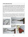
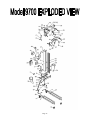
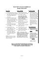
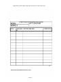
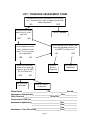
Section 1: User Manual PAGE PAGE PAGE PAGE PAGE PAGE PAGE PAGE PAGE PAGE PAGE PAGE PAGE Section 2: Maintenance Guide PAGE PAGE PAGE PAGE PAGE PAGE PAGE PAGE PAGE PAGE 1 INDEX 2 CAUTIONS 3 MECHANICAL OPERATION 4 MECHANICAL OPERATION VIEW 5 SELECTING THE STYLE OF SLING TO BE USED 5 LIFTING FROM CHAIR TO BED 6 LIFTING FROM BED TO CHAIR & SLING LAUNDERING 7 LIFTING FROM THE FLOOR 8 LIFTING WITH RECUMBENT BARS (optional) 9 CHARGING PROCEDURE 10 CHARGER SPECS & WEIGHING WITH ELECTRONIC SCALE 11 CALIBRATION INSTRUCTIONS 12-14 GENERAL PROCEDURE GUIDE / SAFE WORKING LOADS (Should be copied for each operator and kept with their personnel records.) 15 EXPLODED VIEW 16-17 PARTS LIST 18 SPECIFICATIONS 19 CIRCUIT BOARD WIRING 20-21 TROUBLE SHOOTING GUIDE 22 MAINTENANCE SCHEDULE 23-25 ITEMS TO INSPECT 26 MONTHLY LIFT INSPECTION CHECK LIST (To be copied) 27 LIFT / TRANSFER ASSESSMENT FORM 28 WARRANTY PROBLEMS OR QUESTIONS??? PARTS & SERVICE ConvaQuip Ind., Inc. P.O. Box 3417 Abilene, TX 79604 Phone (325) 677-4177 Toll Free (800) 637-8436 Fax (325) 677-7217 Revised 7/1/09 Page 1 9700 PLEASE READ BEFORE OPERATING 1. Model 9700 IS DESIGNED FOR TRANSFERRING ONLY, NOT FOR TRANSPORTING OVER LONG DISTANCES. 2. FOR THE SAFEST TRANSFER, VOLARO LIFT LEGS MUST BE FULLY EXTENDED INTO THE WIDE POSITION WHEN LIFTING A PATIENT OR RESIDENT. 3. FOR EMERGENCY STOP, PULL BATTERY FROM BATTERY RECEPTACLE. 4. MAKE SURE ALL FOUR LOOPS FROM THE SLING ARE PROPERLY “NESTED” IN THE BOTTOM OF THE HOOKS BEFORE LIFTING OR TRANSFERRING A PATIENT OR RESIDENT AND THAT ALL FOUR RETAINER SPRINGS ARE FUNCTIONING. 5. USE Only Model 9700 SLINGS AND ACCESSORIES DESIGNED FOR USE WITH THE Model 9700 LIFT MODELS. 1. DO NOT PUSH OR PULL ON THE BEAM OR RESIDENT. THIS WILL JEOPARDIZE THE LIFT’S STABILITY. 2. DO NOT USE ANY OTHER BATTERY CHARGER.USE ONLY THE BATTERY CHARGER SUPPLIED WITH THE LIFT. 3. DO NOT EXCEED THE WEIGHT LIMIT LISTED ON THE LIFT 4. DO NOT PLACE FINGERS BETWEEN THE SAFETY GUARDS OF THE BEAM TRACK. 5. DO NOT ATTEMPT A TRANSFER FROM THE FLOOR BEFORE EXAMINING FOR ANY INJURIES THAT MAY NEED SPECIAL ATTENTION. 6. DO NOT USE A SLING THAT SHOWS WEAR, IS TORN, BLEACHED OUT, OR HAS ANY LOOSE THREADS. INSPECT BEFORE EVERY LIFT. Page 2 (Operation Corresponds with the View on Page 4) 1. This lift is powered by a 12VDC removable battery pack located at the back of the lift. The battery fits either way in the lift and charger receptacle to make it easy to remove and replace the battery. NOTE: Battery removal is your emergency stop feature. 2. The lift has a built-in battery indicator which illuminates when the battery is about 60% discharged. This would be the best time to replace with the battery with one that is fully charged. 3. Once the battery is inserted into the charging receptacle, the charge light on the charging unit comes on. Make sure this yellow light comes on to assure your battery is charging. Once the battery is fully charged, the light will shut off. The charger is fully automatic and will quit charging when the battery reaches a full charge. You will not damage the battery or charger if the battery is left plugged in. 4. The lift is operated by switches located at the tips of the handles. This allows proper ergonomics by keeping the hands on the handles while operating the lift and maneuvering it at the same time. 5. The optional hand control provides a second source to operate the lift. This allows the operator to be next to the person being transferred and to operate the lift at the same time. It also aids as a back-up source to operate the lift. 6. If for any reason the lift would stop in mid travel, the first thing to check is the circuit breaker located on the battery receptacle. If the breaker has popped out, simply press it back in and try lifting. If the problem is not the breaker, and you cannot lower the patient/resident by the switch on the handle or the remote control, you must use the manual safety override 5/16‖ x 3/8‖ bit provided with the lift. 7. To operate the lift manually, remove the plastic plug at the top of the mast and use the 5/16" hex driver supplied with the lift, and a 3/8" socket and ratchet with extension. Insert the hex driver into the hex head at the top of the ball screw and simply turn in the desired rotation. 8. The leg adjuster opens and closes the legs of the lift. By pulling back the handle, the pin is pulled out of the notch plate. This allows you to rotate the handle back and forth. Keep the handle pulled back while rotating to keep the pin from rubbing on the notch plate. This process enables the lift to be narrowed to go through doorways and widened to go around a wheel chair or lounge chair. 9. The brakes are located on the rear wheels. Press the tab with your foot to lock the wheel and the pivot. Press the upper portion of the tab forward to release the brakes. Page 3 1. 2. 3. 4. 5. 6. 7. 8. 9. 10. Page 4 12 V BATTERY PAC BATTERY LEVEL INDICATOR BATTERY CHARGER BASE HANDLE UP AND DOWN SWITCHES REMOTE UP AND DOWN SWITHCES CIRCUIT BREAKER PLASTIC PLUG FOR MANUAL OVERRIDE LEG ADJUSTER HANDLE REAR BREAK HANGER ASSEMBLY SELECTING THE STYLE AND SIZE OF SLING TO BE USED The first step is to select the Style of sling to be used. The most common sling is the divided leg sling. The person must have two full legs in order for you to use the divided leg sling. (Not meant for amputees) This sling is designed to be removed from the person after they have been transferred into their wheelchair so the patient does not have to sit on the sling throughout the time they are sitting in their chair. If you find it difficult to remove a divided leg sling from behind a person while they are seated in a wheelchair, you may choose to leave it behind them. However, be sure to observe the correct position of the sling before you lift that person. The sling may have moved. If a person has leg discomfort while you use the divided leg sling on them, we would recommend the hammock sling. If you are lifting a single or bilateral amputee, you must always use a hammock sling. The hammock sling comes with or without the commode hole and with or without head support.. The second step is to determine the proper Size. It’s simple. Lay a sling across the persons chest. If it’s the proper size sling, you will note 2-8 inches of extra material extended past the side of each arm. NOTE: This is only a guide. Body shapes vary so much that fitting the patient to the sling ultimately needs to be determined by the health care professional. If you observe little or no fabric extended past the arms, you must upgrade to a larger sling. All styles have a color coded border to easily indicate the size of sling. (Refer to your sling sizing chart available on the website at www.smths.com) The loops on the straps are color coded to match each side in positioning the sling to the desired location. Changing the orientation of these loops will change the angle of the person being transferred. This comes in handy for charting the colors that would work best for each individual. All sling styles come with built in positioning handles on the back of the sling. These always face out and are used to position a person back in a chair. LIFTING FROM CHAIR TO BED (NOTE: ALWAYS INSPECT THE SLING BEFORE EVERY LIFT—READ CAUTION SHEET) To apply the divided leg sling on someone sitting in a wheelchair, first lean the person slightly forward to get clearance between the back of the person and the back of the wheelchair. Keeping the sling from twisting, work the sling along the crevice between the legs and the chair. Make sure the sling is all the way down and that there is no gap behind the person. If the sling is not all the way down, it will not come under the leg easily. Work the sling alongside the legs, getting as much material going toward the front of the chair as possible. Raise the leg and pull the material through, trying to prevent any wrinkles. Crisscross the inside flaps with the main loops, then thread the strap with the color-coded loops through the main loop. Crisscrossing the inside flaps will keep the legs tight together for a more comfortable and dignified transfer. If during the transfer it is required for the person’s legs to relax open, you can hook it up without crisscrossing the inside flaps. This will allow the legs to relax open. Now that the sling is positioned, bring the lift toward the person, open the legs of the lift to the wide position, lower the hanger until the desired colored loops can be hooked on the hanger. It doesn't matter if the front or back is hooked up first. (NOTE: RAISE UNTIL THERE IS TENSION ON THE STRAPS, THEN DOUBLE CHECK TO MAKE SURE SLING LOOPS ARE NESTED INTO THE BOTTOM OF THE HOOKS PROPERLY.) Now push the up button on the handle or use the remote control to raise the person high enough to clear the bed. Position the lift so that the person will be lowered to the proper position in the bed. Once there is plenty of slack in the straps, remove the loops from the hanger and pull the lift out of the way. Unthread the straps from the main loops. Roll the person on their side and fold the sling, then roll to the other side and remove the sling. Page 5 LIFTING FROM BED TO CHAIR When transferring from bed to chair just reverse the previous steps. Roll the person to their side and fold the sling. Align the bottom of the back of the sling by the tailbone. Roll the person to their side and pull the rest of the sling through, straightening any wrinkles. Bring material under the legs the same way as if they were in the chair. Crisscross the inside flaps and thread the straps through the main loops. Bring the lift in, spread the legs, and lower hanger near the center of the person being transferred. It is recommended to keep the legs in the widest position at all times when transferring a person who is uncooperative or combative. Bend the knees and hook up the color coded loops that were previously used to bring them to a sitting position. Press the button to raise the lift and make sure the material under the leg stays straight toward the knee, keeping out as many wrinkles as possible. Note: Raise until there is tension on the straps and then double-check to make sure the loops are nested in the bottom to the hooks. If the base is in the narrow position, adjust it to the widest position once you are clear from the bed and always before turning the lift. Once the patient is over the chair, lower and guide them by the built-in handles on the sling to bring them back far into the chair. (Do not attempt to move the lift by pushing on the person or the beam.) To remove the sling, reverse the step. Unthread the straps from the main loops, raise the legs, and pull the material aside. Now lean the person forward and pull sling clear. SLING LAUNDERING INSTRUCTIONS Model 9700 (FULL BODY LIFTS) The sling material and webbing are made of nylon. If possible, put the sling in a mesh bag to prevent the straps from getting tangled. Recommended washing instructions are as follows: Machine wash warm - gentle cycle Tumble dry - LOW HEAT ONLY - or drip dry Non-chlorine chemical disinfectants OK NO BLEACH WARNING: EXCESSIVE HEAT AND/OR BLEACH WILL SHORTEN THE SERVICABLE LIFE OF THE SLING. IF THE SLING IS DAMAGED DUE TO IMPROPER LAUNDERING, WARRANTY IS VOID. Page 6 Page 7 RECUMBENT BAR INSTRUCTIONS (optional) The R-bars were developed in response to several requests from customers to develop a system that will transport hip patients. The system will also lift patients whose bodies are rigid. Previous to the R-bar system, nurses had no choice but to lift their patients manually, therefore placing themselves and patients at risk. Caution: Be sure to consult with the patient’s health care provider for proper patient positioning and transport. The R-bar system is designed to be used on Model 9700 LIFT only! Instructions: 1. Assess the Patient: Consult with the patient’s nurse. 2. Prepare the Model 9700: Remove the R-bars from the bag. Attach the R-bars to the Jhooks on the Model 9700 LIFT. Double check the connections. Observe the black nylon loops. If frayed, cease activity and order new loops. Be sure to hang the R-bars directly under each moving hanger bar from the lift. You want the R-bars to mirror image the movement of the existing hanger bars. Do not attach the R-bars perpendicular to the hanger bars. 3. Safety: Observe the R-bar sling you will be using. Check the fabric for tears, holes and frays. If damaged, replace with a new sling. 4. Place the Abductor Pillow: Place the pillow between the groin and the knees. You should be able to read that label as it is placed properly between the legs. 5. Place the Sling: Rest the sling beside the patient. Log roll the patient to one side. Carefully slide the sling underneath the patient. Be sure the bottom of the sling will rest at knee level. Roll the patient back and pull the remaining material out until you see that the patient will be directly in the middle of the sling. 6. Lift the Patient: Open the legs of the Model 9700LIFT. Place the R-Bars directly over the patient. Use the patient’s navel as a centering point. Lower the lift enough to provide ease of sling hook-up. Double check your connections. Adjust the head support. Tell the patient you are about to lift them, then lift. Lift the patient high enough to clear the bed and transport to the nearest recliner. Center the patient over the recliner and lower the patient. DO NOT MANIPULATE THE LIFT BY PULLING ON THE PATIENT! Remove the abductor pillow and leave the sling underneath the patient. Before you lift the patient from the recliner to transport back to bed, check to see that the sling is in the correct lifting position. If not, reposition the sling. Open the legs on the Model 9700 LIFT. Apply the abductor pillow. Lift, Transport and Lower the patient into bed. Unhook the sling and move the lift aside. Remove the sling from under the patient. Observe the sling for contaminants. If soiled, launder per sling instructions. Page 8 CHARGING PROCEDURE 1) The lift has a RED battery indicator light located on the receptacle that will come on when the battery is low. This is the best time to exchange the battery with one that is fully charged from the charger. 2) Locate the charger receptacle near an outlet and on a counter or flat surface where the suction cups will have good contact. 3) Insert the battery. (It will fit in either direction.) 4) Plug in the charger. (Note: if no battery is in the charger the GREEN light will be on.) The RED light may come on briefly if the battery is excessively discharged, but it should go off within the first few minutes followed by the YELLOW light. If the RED light stays on it may mean the battery is extremely discharged. Leave the battery on the charger overnight to see if it can be restored. 5) When the YELLOW light has gone out, the battery is fully charged and will shut off automatically. The GREEN light will stay on. Note: Charging sequence: Insert battery and then plug into outlet for proper electronic function. Leaving the battery on the charger will not cause it to overcharge. If the battery goes to GREEN in a short period it may mean you have a bad cell that will not take a charge. Plug battery into charger every night. Do not remove until charging cycle is complete. Battery will not be damaged if left plugged in. The charger will get warm during its charge cycle. Additional charging information: The Volaro charger uses a three part process and should take about 12 hours. The first part is called the bulk charge. During this stage the charger supplies 1.5 Amps until the battery terminal voltage reaches 13.8 volts. The current then begins to ramp down from 1.5 Amps to about .5 Amps at the conclusion of the charging process. This ramping charge (absorption mode) will take several hours. Finally, the GREEN light will come on indicating that the charger has switched to the third part of the cycle, the temperature compensated float charge. The charger is now in its maintenance mode, keeping the battery in its ideal charged state. The Volaro charger is not a trickle charger nor will the battery be damaged if left permanently attached and powered. If a the GREEN light comes on soon after putting the battery on the charger it means that, either the battery is already charged OR you have a weak battery that will only hold a minimal charge. Maintaining the proper battery voltage when the battery is not in use will extend the service life of the battery. Page 9 Model 9700 CHARGER SPECIFICATIONS Bulk Charge Current 1.5 Amps Bulk Charge Voltage Range 10-14 Volts Absorption Mode Current 1.5 - .5 Amps Absorption Mode Voltage Range 14.0 - 15.0 Volts Float Voltage 13.6 - 13.8 Volts AC Voltage In 115 - 130 VAC Power In 30 Watts WEIGHING WITH ELECTRONIC SCALE (optional) Press the ―ON/ZERO” button to turn on the scale. If ―LOW BAT‖ appears, replace in slide out box on the back of the scale. The scale will take about 5 seconds to zero itself. Attach the desired VOLARO, Fleece Cover, Litter, Recumbent Bars, or anything else you plan to use on the person being weighed, making sure it is not touching anything. (Keep the hand control off the lift while weighing.) Press the ―ON/ZERO” button – The scale counts down for 3 seconds (DO NOT touch lift during countdown, or countdown will reset for additional 3 seconds.) This will place the weight of the sling into memory and the scale will automatically deduct the weight of the sling from the reading. NOTE: To switch from Lbs. to Kilos - Press and hold the LB/KG button until ”CONV” disappears. Press and hold again to convert back to Lbs. (Note: this may trigger a need to recalibrate after weighing.) Now with the scale still on, remove the sling and place it beneath the person to be weighed. NOTE the appearance of the screen. You will see a flashing #. This is the weight of the items previously weighed. They will automatically be subtracted from the person’s weight. This reading will stay in memory even if the scale is turned off or the battery is removed. Attach and lift the person clear of chair or bed. Once the reading is steady, the scale will lock on to the reading to make it easier to read if the person starts to move. NOTE: Before you record weight, Be Sure That You Are Not Touching Lift. This will show a false weight. Let weight steady and record reading. Scale shuts off automatically after two minutes when not in use. Press the recall button to review the last recorded weight. (See Calibration Procedures on the next page.) Page 10 HANGING AND DUAL DISPLAY SCALE CALIBRATION INSTRUCTIONS Model 9700 1. Should calibration be necessary, all that is required is a 25 lb. precision weight. Do not use packaged goods, fitness weights, or other items that say they weigh 25 lbs. Failure to use a precision weight may cause the scale to display an inaccurate weight. Using a certified weight is the method preferred. 25 lb. certified weights are available from SMT Health Systems. 2. When calibrating scale, remove hand control from the lift and have the beam positioned in the middle of its stroke. 3. To enter calibration mode, push “ON/ZERO” button. 4. While holding the “ON/ZERO” button, press and hold the “LB/KG” button. After approximately 3 seconds the message on the display will change from “ZERO” to “CAL”. Release both and the display will show “C O”. 5. Hang strap or sling that will hold calibration weight on the hanger hooks. If using a sling, make sure it is empty. Push the “ON/ZERO” button and release. The display will count down from “16” to “0”. When finished the display will show the message “C 25”. 6. Now hang 25 LB. calibration weight on strap which you previously attached to the hanger (step 4, above) or place it in the sling and permit the scale to stabilize. (Failure to stabilize the unit may cause the scale to display an inaccurate weight – see below.) 7. Push “ON/ZERO” button again. Scale will count down from “16” to “0” as before and then the display should read “25”, which is the weight of the calibration weight. Calibration is now complete. DO NOT TOUCH LIFT WHILE IT IS COUNTING DOWN. 8. Remove the 25 lb. precision weight, stabilize the sling or strap, and press the “ON/ZERO” button to zero the scale. The scale is ready to use. Notes on how to stabilize the unit: Weight must be centered directly below the beam Do not side load the scale Permit the weight to stop bouncing or swinging NOTE: Switching between lbs. and kg. may trigger a need to recalibrate. Call ConvaQuip Customer Service if you have any questions. Page 11 This form is intended as a guide to help you develop a procedure sheet that will fit your specific application in your facility. It is recommended that everyone be in serviced by the company representative or use the manufacturer’s in-service video before operating any mechanical lift. (This for should be copied for each operator and kept with their personnel records.) Staff Name: Date: Checked Off By: General Preparation: Yes No 1. Identify the resident. 2. Explain what you are going to do 3. Wash hands. 4. Get supplies ready, sling, wheelchair, blanket or lap robe. 5. Get Help from experienced team member for this procedure. 6. Have assistant stand on opposite side of bed to assist with transfer. 7. Provide privacy. Pull curtain all around the bed. General Procedure: Yes No 1. Position wheelchair at foot of bed. 2. Adjust bed to working level. 3. Make sure battery indicator does not indicate a low battery. (If so replace) 4. a.) Examine lift sling for any damage: tears, frays, or weak areas. b.) Make sure the correct size sling is to be applied. c.) If weighing resident, hang the sling on the hanger hooks, press the on button Page 12 Yes No 5. Lower side rails. 6. Roll resident to one side and place sling, folded halfway under resident. Top of sling should be approximately at shoulder blade area. Bottom of sling should be approximately near the tail bone. 7. Roll resident to other side and pull rolled half of sling through. Smooth sling and check correct placement. 8. Roll resident onto center of sling. Pull padded legs on sling along each side and wrap inside thigh areas close to groin area. Crisscross straps through the holes before hooking to the lift. 9. Raise head of bed slightly 10. Position lift over bed and instruct assistant to help guide lift into proper position. 11. Check that base legs of lift are in wide position where applicable. If base position must remain in a narrow position, make sure the lift area between bed and chair are clear of any obstacles. Widen once clear from bed. 12. Attach straps on sling to lift with the strap ―nesting‖ in the bottom of the hook. Remember, with the divided leg sling, the straps at the thigh area must be crisscrossed at the hanger before lifting. 13. Tell assistant to guide resident as you begin to lift them from the bed using ―up‖ button on hand control or up button at handle grips. Once there is slight tension on the straps check to make sure all four loops are still nested in the bottom of the hooks before lifting. 14. Lift resident until buttocks have cleared the bed. Give reassurance to allay fears. If weighing, steady resident and look at the reading on the scale. 15. Tell assistant to steady the resident in lift and guide to position over wheelchair, trolley, tub lift, etc. CAUTION: Push and turn the lift from the handles only. Pushing on the top of the beam or on the resident could jeopardize the lift’s stability. 16. Lock wheelchair brakes. 17. Instruct assistant to stand behind wheelchair and place hands in positioning straps on both sides of sling while the resident is coming down pull the handles back to position the resident in an upright position. Page 13 Yes No 18. Disconnect all straps from the hanger and remove sling by raising legs and pulling along sides. Ask resident to lean forward as you assist and support them to remove for back and hip area. 19. Move lift away and adjust for comfort. Apply safety belt if ordered. Position feet on foot pedals. 20. Cover lap with blanket and leave call light within reach. 21. Wash hands. report reaction and overall tolerance to team leader. SAFE WORKING LOADS Model 9700 Patient slings have been developed, tested and manufactured to have a safe working load of 1000 lbs. Due to the variety of resident shapes and dimensions, the appropriate size should be selected to accommodate specific patients. Care should be taken to ensure that the mechanical lift selected has the capacity to safely lift the resident. The Sling Sizing Chart is designed only to suggest which resident will safely fit into the sling based on their size and weight. (Sling sizing chart is available on the ConvaQuip website www.convaquip.com/sling_chart.pdf ) NOTE: Lifts are designed to ―transfer‖ a resident, not ―transport‖ them. Page 14 Page 15 ITEM # QTY PART # DESCRIPTION 1 1 HC45001A HD Frame Assembly 2 1 PC45001A PC Frame Assembly 3 1 PC45002A Mast & Base Plate Assembly 4 2 PC4003A Leg Assembly 5 1 PC45020 Notch Plate 6 1 10015-1 Power Box Assembly 7 2 2293 Rear Caster Mount Cap 8 1 PC45022 Safety Limit Switch 9 2 2196 / LT2046 PC 4” Rear Caster / HD 5” Rear Caster (with brake) 10 2 2003 / 2034 PC 3” Dual Caster / HD 4” Single Caster 11 1 PC45005A Counter Balance Spring Mount Assembly 12 1 PC45026 Mast Cap 13 1 PC45027 Actuator Support Bearing 14 1 PC45023-1 Actuator Support Bearing Mount 15 1 PC45031NS Non Scale Beam (Optional) 16 1 PC45006A Scaled Beam Assembly (Optional) 17 4 2013 Cam Follower 18 4 PC45037 Carriage Slide Block 19 4 35237-1 Nylatron Roller 20 1 2039 Actuator Assembly 21 1 PC45008A Handle Bar Assembly 22 2 2008 Red Push Button Switch 23 1 PC4509A-1 Leg Adjuster Handle Assembly 24 1 35506-2 Scale Cover (Optional) 25 4 2159 Saddle Bag Strap Retainer 26 2 35005-2 Saddle Bag 27 2 2125 Mast Plug 28 1 2279 Mast Cap Plug 29 1 PC45056 Lower Circuit Board Mount (Optional) Page 16 30 1 PC45057 Upper Circuit Board Mount (Optional) 31 1 2743 Scale Battery Box (Optional) 32 1 2791 Scale Circuit Board (Optional) 33 1 PC45060 Load Cell (Optional) 34 1 PC45031-1 Non Scale Adapter (Optional) 35 1 2087 Counter Balance Spring 36 2 35022-1 Mast Brush Holder 37 2 35021-1 Mast Brush 38 2 45023-1 Leg Adjuster Rod Assembly 39 2 PC45065-1 Leg Bumper 40 1 50178-1 Actuator Mount Bushing 41 1 10006-A2 Charger Assembly (includes 2026 transformer) 42 1 10047-2 Remote Hand Control 43 2 35506-2 Scale Face Plate 44 1 PL10004A Hanger Assembly 45/46 1 70756 Strap Retainer & Spring Kit (set of 4) 47 2 2033 Hanger Thrust Bearing 48 2 2035 Leg Bearing 49 1 PP40053-1 Leg Adjuster Spring (Urethane) 50 1 PA62201-1 Remote Holder 51 1 PL44000 Hanger Cover Center 52 2 PL44001 Hanger End Cover 53 1 PL44002 Beam End Cover 54 1 10048-2 12V Battery Assembly (Cell-2001) 55 1 2026 Wall Transformer (White) 56 1 2272 Square End Cap 57 1 2006 Adjuster Handle Grip 58 2 2102 Foam Handle Grip Page 17 450 LBS Lifting Capacity—PC450 700 LBS Lifting Capacity—HD450 (NOTE: Base on HD450 is 5‖ wider in both open and closed positions) 1000 LBS Lifting capacity (see manual for model HD1000) Non-Arcing Lift Beam Thrust Bearing Mounted Hanger Spring Retainer Clips Vinyl Safety Padding Vinyl Storage Bags Plastic Case Batteries with Cushion Grip Handles, 12VDC 12Amp/Hr Gel Cell 12VDC Ball-Screw Actuator with 1‖ diameter screw. Steel Hand Control Powder Coat Paint 3 Position Positive Lock Leg Adjuster Abuse-Resistant Scale, Mounted in Beam High Impact ABS Leg Covers Front Casters 3 ‖ Dual Swivel Rear Casters 4‖ Single Swivel w/Brake Safety Pressure Switch Manual Override Page 18 Model 9700 ~ MAINTENANCE MANUAL 1 5 2 6 3 7 4 8 1 - POSITIVE POWER LARGE RED 5 - POSITIVE UP TO SWITCH SM GREEN 2 - POSITIVE TO SWITCH SMALL RED 6 - NEGATIVE POWER LARGE WHITE 3 - UP THUMB SWITCH & REMOTE - 2 SMALL BLACK 7 - SAFETY SWITCH 1 SMALL PURPLE 4 - MOTOR - LARGE RED 8 - MOTOR - LARGE BLACK NOTE: 3 WHITE WIRES ARE ATTACHED TOGETHER WITH WIRE NUTS Circuit board plug position relative to relays may vary on different boards. Page 19 Patient Lift Model 9700 Model 9700S (W/SCALE) PROBLEM CAUSE SOLUTION LIFT 1. Lift won’t go up. 1. 2. 3. 4. 5. 6. Bad lift control switch Dead battery Hand control is broken Actuator not working Battery is not making connection Circuit Breaker popped 1. Remove and replace 2. Switch batteries 3. Send in hand control for repair or order new parts 4. Replace motor 5. Make sure battery pack is making contact with terminals in the receiver box; replace terminal contacts. 6. Push in circuit breaker ACTUATOR 1. Actuator makes noise 1. Not enough grease on actuator 2. Loud ticking noise when lift goes up and down 3. Faulty or worn out actuator 1. Put #2 grease on the full length of the actuator screw 2. Replace actuator nut 3. Replace actuator 1. Batteries are worn out or circuit board is bad 2. Batteries are not being charged when the RED charge battery light comes on 1. Order new batteries or order new circuit board 2. Leave battery on overnight; order new batteries; also make sure that you charge the batteries when the RED light comes on at the lift. 1. Fuse is blown in the Transformer 2. Electrical outlet may not be operational 1. Order a new transformer 2. Yellow light does not come on when battery is inserted 1. Charger bad – verify by using new battery 2. Battery dead 1. Order new charger 2. Order new battery 3. Red light stays on 1. Battery shorted or reversed leads 2. Charger needs to be reset 3. Battery is totally discharged 1. Check terminal contact springs for wear and replace 2. Take out battery, unplug transformer, but battery back in, plug in 3. Leave battery on charger for 24 hours to see if it will revive. BATTERY PACK 1. Charge battery light stays on constantly 2. Batteries wearing out too quickly BATTERY CHARGER 1. Battery charger lights do not come on when plugged in Page 20 2. Use different outlet Patient Lift Model 9700 Model 9700S (W/SCALE) TROUBLESHOOTING and MAINTENANCE GUIDE PROBLEM CAUSE SOLUTION SCALE 1. Inaccurate weights 1. Not zeroing out scale properly 2. ―Lb‖ to ―Kg‖ switch is in the wrong setting 3. Batteries in scale are low 4. Person in lift is moving excessively while taking weight 5. Scale is out of calibration 1. Zero scale according to instructions 2. Switch to desired setting 3. Replace the four ―AA‖ batteries in scale 4. Make sure the patient is hanging evenly under the hanger and there is minimal movement 5. Calibrate the scale following the calibration instructions 2. Display is erratic 1. ―AA‖ batteries in scale low. 2. Scale is out of calibration 3. Wire from load cell to circuit board is loose. 4. Circuit board is bad 5. Load cell is bad 1. Replace four ―AA‖ batteries 2. Calibrate scale 3. Remove battery box and check connection 4. Replace circuit board 5. Replace load cell 3. Display is blank 1. Power to scale is not turned on 2. 4 AA batteries are bad 3. Scale is damaged 1. Turn scale on 2. Replace batteries 3. Call tech. support for instructions Page 21 MAINTENANCE SCHEDULE Model 9700 LIFT Every Day Every 3 Months Periodic Testing General Lift CondiAfter each person you lift, Lube pivot points on lift tion: A general visual you should check the sling, Grease actuator with a good inspection of the exterand wash if needed. Refer heavy duty #2 grease. nal parts and all functo the Sling laundering in(Note: DO NOT USE A tions can be carried out structions SILICONE OR WD 40 at any time to ensure Check the condition of all TYPE LUBRICANT ON no adverse damage has slings. If you are in doubt THE ACTUATOR) occurred. If any of its operational ability to Check leg adjuster stop for doubt, withdraw the safely lift a person, then signs of wear equipment from use discard the sling and order Check the movement of the and call the Convaa new sling lift; remove hair from the Quip Service DepartCheck to see that strap recasters if needed ment. tainer flapper and spring Check leg covers; if cracked are working. replace with new Other Maintenance Check the lift; if the Check all vinyl covers; if ―RED‖ light is on , then worn, replace with new Hanger bolt must be charge the batteries Check all external fittings; replaced every three Keep your Model 9700 tighten where needed years. lift clean by wiping it down with a damp cloth. NOTE: At the back of this Actuator bearing Use a mild detergent if manual you will find a sample (ball screw nut) must needed monthly inspection sheet and be replaced when check off list. We encourage grinding wear is NOTE: Do not use a petroyou to make copies for each heard but not longer leum based solvent on paint, lift and keep for your records. than 5 years. stickers, or plastic. (800) 637-8436 THIS IS A SUGGESTED MAINTENANCE SCHEDULE DEPENDING ON USE. THE EQUIPMENT MAY NEED TO BE INSPECTED MORE FREQUENTLY. Page 22 LIFT ITEMS TO INSPECT 1. HANGER: FULL BODY LIFT STRAP RETAINER SPRINGS ATTACHING HARDWARE BEARINGS ARM PIVOT PADDING HANGER BOLT REPLACED EVERY THREE YEARS 2. Y-BEAM: STAND LIFT STRAP RETAINER SPRINGS PADDING 3. BOLTS AND NUTS TORQUE BOLTS UNDER BEAM PADDING TO 55 POUNDS CHECK ALL BOLTS AND NUTS 4. LEG ADJ. HANDLE CONDITION (Check wear at pivot points.) ATTACHING HARDWARE SPRING 5. LEG ADJ. NOTCH PLATE WEAR (Are legs kept securely in locked position?) ATTACHING HARDWARE 6. LEG ADJ. STOP PIN/ ROD WEAR 7. LEG LINKAGE HARDWARE CONDITION 8. SLINGS (Reasons to discard) WORN FRAYED BLEACHED OUT 9. ACTUATOR: NOISE-UP/DOWN (Replace bearing after 5 years.) WITH AND W/O WEIGHT GREASE (should be greased at least semi-annually) 10. SCALE: ACCURACY (Calibration needed?) BATTERIES MOUNT Page 23 11. POWER BOX: PLASTIC GUIDES TERMINALS (Bent or worn) 12. LED: REMOTE JACK HOLDER OR LENS 13. THUMB SWITCHES LEFT AND RIGHT 14. REMOTE SWITCHES STRAIN RELIEF CORD (Replace if stretched out or cut.) 15. CASTERS BRAKES SWIVEL ROLL BEARINGS 16. LEG BUMPERS CRACKED OR MISSING 17. KNEE REST: (STAND LIFT) SAFETY STRAP PADDING PIVOT ADJUSTING PINS/KNOBS 18. CHARGER OPERATION LIGHTS TERMINALS (Bent or worn) 19. BATTERIES LOAD TEST AGE 20. GRIPS 21. LEGS PIVOT ATTACHING HARDWARE ALIGNMENT Page 24 22. WELDS VISUALLY INSPECT FOR CRACKS 23. PAINT 24. BEAM SAFETY SWITCH LIFT UP ON BEAM WHILE HOLDING DOWN BUTTON 25. DECALS CORRECT MISSING 26. OTHER: Page 25 FORM SHOULD BE COPIED AND USED ON EACH LIFT FOR ONE YEAR Page 26 LIFT / TRANSFER ASSESSMENT FORM CAN INDIVIDUAL SAFELY PERFORM > OR = 50% OF LIFT / TRANSFER WITH ONLY STANDBY ASSISTANCE FROM CAREGIVER? NO YES CAN INDIVIDUAL BEAR NO LIFT NEEDED WEIGHT ON AT LEAST ONE LEG? YES NO DOES THE INDIVIDUAL DOES THE INDIVIDUAL WEIGH LESS HAVE MODERATE UPPER BODY STRENGTH AND ABILITY TO FOLLOW SIMPLE COMMANDS? YES THAN THE MAXIMUM CAPACITY OF THE SMT FULL BODY LIFT? NO NO DOES THE INDIVIDUAL WEIGH LESS THAN THE CAPACITY OF THE SMT SIT-TO-STAND LIFT YES SIT-TO-STAND REQUIRED YES CONTACT SAFETY COMMITTEE FULL BODY LIFT REQUIRED NO CONTACT SAFETY COMMITTEE Patient Name _________________________ ID#_________________Room#_____ Assessment Completed by____________________________Date_____________ Lift(s) Required___________________________Sling Size___________________ Comments for PRN Use_______________________________________________ Assessment Updated by_____________________________ Date_____________ _____________________________Date_____________ _____________________________Date_____________ Assessment Care Planned by_________________________Date_____________ Page 27 1 YEAR *LIMITED WARRANTY ON ALL PARTS ONLY UNDER CONDITIONS OF NORMAL AND INTENDED USE. *10 YEAR WARRANTY ON THE MAIN STRUCTURE OF THE LIFT. MISUSE, DAMAGE OR ALTERATION OF BODY LIFT OR ANY OF ITS PARTS, VOIDS THE WARRANTY. NO OTHER WARRANTIES WRITTEN, VERBAL, IMPLIED OR OTHER THAN LISTED HERE WILL BE HONORED. *SHIPPING CHARGES NOT INCLUDED. CONVAQUIP IND., INC. P.O. BOX 3417 ABILENE, TX 79604 CUSTOMER SERVICE: PHONE: (325) 677-4177 or (800) 637-8436 FAX 325-677-7217 www.convaquip.com Page 28