1
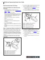
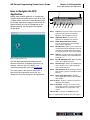
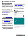
General Motors
Service
Programming
System
User’s Guide
IMPORTANT NOTICES
SAFETY
All Warning, Caution, Important, and Notes messages must be followed for your safety. These safety messages
are in the following formats:
Warning:
•
Means you may risk serious bodily harm or loss of life.
Caution:
•
Means you may risk moderate bodily harm, property (vehicle) damage, or tool damage.
Important:
•
provides information demanding special attention.
Notes: are special information to provide clarity and helpful tips.
These safety messages cover situations SPX is aware of. SPX cannot know, evaluate and advise you as
to all of the possible hazards. You must be certain that any conditions or service procedures encountered
do not jeopardize your personal safety.
COPYRIGHT
No part of this manual may be reproduced, stored in a retrieval system or transmitted, in any form or by any
means, electronic, mechanical, photocopying, recording, or otherwise, without the prior written permission
of SPX.
DISCLAIMER
All information, illustrations, and specifications contained in this technical instruction manual are based on the
latest information available at the time of publication. The right is reserved to make changes at any time without
obligation to notify any person or organization of such revisions or changes. Further, SPX shall not be liable for
errors contained herein or for incidental or consequential damages (including lost profits) in connection with the
furnishing, performance or use of this material.
TRADEMARKS
SI 2000, SPS, TIS 2000, are registered trademarks of General Motors Corporation. Microsoft, Microsoft Windows
and MS-DOS are trademarks or registered trademarks of Microsoft Corporation. Windows screen shots are used
for instructional purposes. All other product names mentioned here are used for identification purposes only and
may be the trademarks of their respective companies.
This manual tells you how to use the General Motors Service Programming System application, any vehicle
specific information given is for purposes of illustration only.
© 2004 SPX Corporation. All rights reserved.
General Motor’s
Techline Information System
(TIS) 2000
Service Programming System
Application for
General Motors
Reprogrammable Controllers
GM Service Programming System User’s Guide
Contents
Contents
Chapter 1: Software Installation . . . . . . . . . . . . . . . . . . . . . . . . . . 1
General Information . . . . . . . . . . . . . . . . . . . . . . . . . . . . . . . . . . . . . . . . . . .
Software CDs . . . . . . . . . . . . . . . . . . . . . . . . . . . . . . . . . . . . . . . . . . . . . . . .
System Requirements . . . . . . . . . . . . . . . . . . . . . . . . . . . . . . . . . . . . . . . . . .
Before You Begin . . . . . . . . . . . . . . . . . . . . . . . . . . . . . . . . . . . . . . . . . . . . . .
Installation Procedures . . . . . . . . . . . . . . . . . . . . . . . . . . . . . . . . . . . . . . . .
Installation Overview . . . . . . . . . . . . . . . . . . . . . . . . . . . . . . . . . . . . . . . . . . .
Check and / or Install TCP/IP Protocol . . . . . . . . . . . . . . . . . . . . . . . . . . . . .
Install the SPS Software . . . . . . . . . . . . . . . . . . . . . . . . . . . . . . . . . . . . . . . .
Update the SPS Data . . . . . . . . . . . . . . . . . . . . . . . . . . . . . . . . . . . . . . . . . .
Software Removal (Uninstall) . . . . . . . . . . . . . . . . . . . . . . . . . . . . . . . . . . .
Troubleshooting . . . . . . . . . . . . . . . . . . . . . . . . . . . . . . . . . . . . . . . . . . . . . .
Troubleshooting Routine . . . . . . . . . . . . . . . . . . . . . . . . . . . . . . . . . . . . . . . .
USB Device or COM Port Conflicts . . . . . . . . . . . . . . . . . . . . . . . . . . . . . . . .
NOTES: . . . . . . . . . . . . . . . . . . . . . . . . . . . . . . . . . . . . . . . . . . . . . . . . . . . . .
1
1
1
2
2
2
2
4
7
7
8
8
8
9
Chapter 2: SPS Application . . . . . . . . . . . . . . . . . . . . . . . . . . . . . 11
Introduction . . . . . . . . . . . . . . . . . . . . . . . . . . . . . . . . . . . . . . . . . . . . . . . .
Software Update. . . . . . . . . . . . . . . . . . . . . . . . . . . . . . . . . . . . . . . . . . . . .
Vehicle Diagnosis. . . . . . . . . . . . . . . . . . . . . . . . . . . . . . . . . . . . . . . . . . . .
Equipment Setup . . . . . . . . . . . . . . . . . . . . . . . . . . . . . . . . . . . . . . . . . . . .
Tech 2 Flash Setup . . . . . . . . . . . . . . . . . . . . . . . . . . . . . . . . . . . . . . . . . . .
Next Generation Scan Tool Setup . . . . . . . . . . . . . . . . . . . . . . . . . . . . . . . .
Service Programming Cautions . . . . . . . . . . . . . . . . . . . . . . . . . . . . . . . .
How to Navigate the SPS Application . . . . . . . . . . . . . . . . . . . . . . . . . . .
Service Programming System . . . . . . . . . . . . . . . . . . . . . . . . . . . . . . . . .
How to Program an Electronic Control Module (ECM) with SPS. . . . . . . . .
How to Check the Programming . . . . . . . . . . . . . . . . . . . . . . . . . . . . . . . . .
11
11
11
11
11
14
16
17
18
18
23
Appendix. . . . . . . . . . . . . . . . . . . . . . . . . . . . . . . . . . . . . . . . . . . . . 25
Next Generation Scan Tool Special Instructions . . . . . . . . . . . . . . . . . .
Vehicle Configuration Index (VCI) Information . . . . . . . . . . . . . . . . . . . .
About VCI . . . . . . . . . . . . . . . . . . . . . . . . . . . . . . . . . . . . . . . . . . . . . . . . . .
How to get a GM VCI. . . . . . . . . . . . . . . . . . . . . . . . . . . . . . . . . . . . . . . . . .
25
26
26
26
Vehicle Coverage Tables . . . . . . . . . . . . . . . . . . . inside back cover
i
ii
GM Service Programming System User’s Guide
Software License and Warranty
Software License and Warranty
GENERAL MOTORS SERVICE PROGRAMMING SYSTEM
SOFTWARE SUBLICENSE AGREEMENT
The software and data encoded on the enclosed disks are the property of General Motors Corporation, a
Delaware corporation (“GM”). GM has authorized SPX Corporation, a Delaware corporation, (“Sublicensor”) to
grant to purchasers of the General Motors Service Programming System a sublicense to the Software, as defined
below, under the terms of this Software Sublicense Agreement (“Agreement”). USE OF THE ENCLOSED DISKS
OR SOFTWARE CONSITUTES YOUR AGREEMENT AND ACCEPTANCE OF SUCH TERMS.
1.0
Definitions.
(a)
“Software” shall mean that GM’s proprietary computer software program called General Motors Service
Programming System containing the technical service information (and updates thereto) provided by GM
(Sublicensor) in object code form or suitable media and the documentation provided in connection with the
program. “Software” shall also include any and all improvements, enhancements and modifications which
are made to the Software during the term of this Agreement.
(b)
“Hardware” shall mean a computer based system.
(c)
“Site” shall mean a building or geographically contiguous buildings (i.e., adjacent tracts or parcels of real
property separated, if at all, only by publicly dedicated rights of ways or private easements), each of which,
in whole or in part, is occupied by End User.
2.0
Sublicense.
(a)
Sublicensor hereby grants to End User, and End User hereby accepts from Sublicensor a nonexclusive and
nontransferable license (the “Sublicense”) to install, use, execute and display the object code version of the
Software and the technical service information contained therein only on one piece of Hardware at End
User’s site at any given time, and End User may only copy the Software as necessary for archival, maintenance or back-up purposes. If End User desires to run the Software simultaneously on more than one piece
of Hardware for the purpose of transferring operations from one (1) piece of Hardware to another piece of
Hardware, End User may operate the Software on two (2) pieces of Hardware only for the period of time
reasonably necessary to complete the transfer.
(b)
The Software may be installed and used on a local area network located at the End User’s Site, so long the
Software is used, executed or displayed only by one user or at one piece of Hardware on the network at any
time.
(c)
End User acknowledges that this License is for internal use only and agrees not to re-license, re-sell, or use
the Software or the technical service information contained therein for any unauthorized commercial
purposes, including but not limited to, using the Software or technical service information contained therein
in any data retrieval, timesharing, or similar system which would permit the Software or technical service
information contained therein to be utilized by anyone other than employes of End User.
(d)
End User shall not at any time, during the term of this Agreement or thereafter, without the prior written
consent of GM, (i) reverse assemble, reverse compile, create or recreate or attempt to create or recreate
the source code, object code, or other aspect of the Software, or allow any third party to do so (ii) permit any
third party or entity to copy, reproduce or duplicate any physical embodiment of the Software (including the
technical service information contained therein) or any documentation connected therewith, or (iii) make any
alterations, modifications, enhancements or derivative works from or to the Software or the technical service
information contained therein.
GM Service Programming System User’s Guide
Software License and Warranty
(e)
End User agrees not to remove or destroy any copyright notice or other proprietary markings or proprietary
legends placed upon or contained within the Software or any related materials or documentation.
(f)
End User agrees that violation of this Section 2.0 shall be a material default of this Agreement and shall
entitle General Motors Corporation (“GM”), Sublicensor or their parents, subsidiaries, affiliates or agents (i)
to injunctive relief to prevent further violation, (ii) to terminate this Agreement immediately and (iii) to seek
any other remedy available at law or in equity.
3.0
Term, Updates.
(a)
Term. The license granted under this Sublicense shall commence upon use of the Software and shall
continue in effect for the period designated on Sublicensor’s Order Form, unless earlier terminated in accordance with the provisions of this Agreement.
(b)
Updates. Sublicensor shall provide appropriate updates to the Software to End User.
4.0
Fee, Payment.
The Sublicense fee for use of the Software and updates thereto shall be in accordance with Sublicensor’s
published price list. Payment shall be due and payable by End User upon execution of this Agreement and
each anniversary of the Effective Date or other period indicated on Sublicensor’s Order Form, unless terminated earlier as provided herein.
5.0
Update Installation.
End User is responsible for the installation of Software updates into its system.
6.0
Ownership.
GM shall retain title at all times to the Software, and End User shall have no rights therein except to use it
as set forth herein.
7.0
Confidential Information and Nondisclosure.
End User acknowledges that the Software and the technical service information contained therein are and
are composed of confidential and/or proprietary data, know how and valuable trade secrets of GM. End User
agrees that the Software (including the technical service information contained therein) was and shall be
received in strict confidence and that the End User will use the Software (including the technical service
information contained therein) solely for its own internal business purposes and will not disclose the
Software in any form (including methods or concepts utilized therein or the technical service information
contained therein) to anyone, except to employes of End User to whom such disclosure is necessary for the
use of the Software by treating the Software with the same degree of care as End User treats confidential
information of its own which it does not wish to be disclosed to the public. End User will notify each employe
to whom any such disclosure is made that such disclosure is made subject to the restrictions contained
herein to be complied with by such employe. End User will take whatever steps are appropriate to assure
that each employe complies with the nondisclosure obligations of this provision. End User agrees that
violation of this Section 7.0 shall constitute a material default of this Agreement and shall entitle Sublicensor,
GM, or their suppliers (i) to injunctive relief to prevent further violation, (ii) to terminate this Agreement
immediately, and (iii) to seek any other remedy available at law or in equity.
iii
iv
GM Service Programming System User’s Guide
Software License and Warranty
9.0
Trademarks and Trade Names.
End User recognizes the exclusive rights of GM and Sublicensor in their trademarks and trade names, and
the good will associated therewith, and End User agrees to conduct its business in a manner consistent with
the protection of such exclusive rights. Specifically, and without limiting the foregoing, End User agrees not
to use in its corporate or business name any Sublicensor trademark or trade name.
10.0 WARRANTY.
THIS SOFTWARE IS PROVIDED TO END USER AS IS AND WITH ALL FAULTS. NEITHER SUBLICENSOR NOR GM MAKES ANY WARRANTIES WHETHER EXPRESS OR IMPLIED, INCLUDING
WITHOUT LIMITATION, THE IMPLIED WARRANTIES OF MERCHANTABILITY OR FITNESS FOR A
PARTICULAR PURPOSE WITH RESPECT TO THE SOFTWARE, ITS USE, OR ANY INFORMATION OR
DATA CONTAINED WITHIN THE SOFTWARE. THIS LIMITATION AND EXCLUSION OF WARRANTIES
WAS A MATERIAL FACTOR IN THE ESTABLISHMENT OF THE LICENSE FEE CHARGED FOR THE
SOFTWARE.
11.0 Indemnity.
End User shall defend, hold harmless and indemnify Sublicensor and its suppliers from any against any and
all claims, actions, damages, liabilities, costs, and expenses (including attorney’s fees and expenses) and
for any damages, injuries, losses or any destruction of property of End User or any third party or any
employe or invitee of End User or any third party, which damage, injury, loss of destruction results directly
or indirectly from or arises out of the use of the Software or Sublicensor’s performance or nonperformance
under this Agreement.
12.0 Limitation of Liability.
IN NO EVENT WILL SUBLICENSOR OR GM BE LIABLE TO OR THROUGH END USER FOR: (1) ANY
INDIRECT, PUNITIVE, SPECIAL, INCIDENTAL AND/OR CONSEQUENTIAL DAMAGES (INCLUDING,
BUT NOT LIMITED TO LOSS OF USE, REVENUE OR PROFITS, ANTICIPATED SALES, BUSINESS
OPPORTUNITIES, GOODWILL OR INTERRUPTION OF BUSINESS) SUFFERED BY END USER FOR
ANY REASON: (2) ANY DAMAGES SUFFERED BY END USER AS A RESULT OF END USER’S FAILURE
TO LIVE UP TO END USER’S OBLIGATIONS UNDER THIS AGREEMENT: (3) ANY CLAIM AGAINST END
USER BY ANY THIRD PARTY FOR DAMAGES OF ANY KIND, INCLUDING ANY WHICH MAY ARISE
FROM OR IN CONNECTION WITH THE DELIVERY, USE, OR PERFORMANCE OF SOFTWARE EVEN
IF SUBLICENSOR OR GM HAS BEEN ADVISED OF THE POSSIBILITY OF SUCH LOSS OF DAMAGE.
The liability of Sublicensor or GM from any and all causes, whether for negligence, breach of contract,
warranty or otherwise, shall in the aggregate, not exceed the sublicense fee paid by End User hereunder.
In addition to the foregoing, End User acknowledges and agrees that neither Sublicensor nor GM make any
representations with respect to the completeness or accuracy of any data provided hereunder and shall
have no liability whatsoever to End User in the event data contained in the Software proves to be incomplete
or inaccurate in any respect.
GM Service Programming System User’s Guide
Software License and Warranty
13.0 Termination.
Sublicensor may terminate this Agreement immediately upon any default by End User of any of the terms
of this Agreement including failure to pay the Sublicense fee noted on Sublicensor’s Order Form. Upon
termination of this Agreement, End User shall promptly return to Sublicensor or destroy all originals and
copies, including partial copies, of the Software and any related documentation, including technical service
information, in End User’s possession. Upon request, End User shall, through an officer or other duly authorized representative of its organization, certify in writing such destruction.
14.0 Governing Law.
This Agreement shall be construed in accordance with and governed by the laws of the State of Michigan,
United States of America, and the courts of the State of Michigan, United States of America shall have
exclusive jurisdication over any disputes arising hereunder.
15.0 Binding Nature and Assignment.
This Agreement shall be binding on the parties hereto and their respective successors and assigns, but End
User may not, nor shall it have the power to, assign this Agreement without the prior written consent of Sublicensor.
16.0 Survival of Terms.
The provisions of Sections 2.0, 6.0, 7.0, 8.0, 9.0, 11.0, 12.0, 14.0, 16.0, 21.0, 22.0 and 28.0 shall survive
the termination or expiration of this Agreement for any reason.
17.0 Sole Agreement of Parties.
Except as otherwise provided or referred to herein, Sublicensor has made no promises to End User and
there are no other agreements or understandings, either oral or in writing, between the parties affecting this
Agreement or relating to any of the subject matters covered by this Agreement.
Except as otherwise provided herein, this Agreement cancels and supersedes all previous agreements
between the parties that related to any matters covered herein.
No agreement between Sublicensor and End User which relates to matters covered herein, and no change
in, addition to or erasure of any printed portion of this Agreement, will be binding unless it is approved in a
written agreement executed by duly authorized representatives of both parties.
18.0 Force Majeure.
Any delay in or failure of the performance of either party hereunder shall be excused if and to the extent
caused by occurrences beyond such party’s control, including, but not limited to, acts of God; fire or flood;
war, government regulations, policies, or actions; any labor, material, transportation or utility shortage or
curtailment; or any labor trouble in the plants of Sublicensor, GM or its or their subsidiaries, affiliates and
suppliers.
19.0 Assignment of Rights of Delegation of Duties.
Sublicensor may assign this Agreement and any right or obligation hereunder to any affiliated or successor
company and will provide written notice of such assignment to End User. In addition, Sublicensor may
delegate the performance of any obligation hereunder to any affiliated or successor company.
20.0 End User’s Responsibility for its Operations.
Except as provided otherwise in this Agreement, Sublicensor has no liability in connection with the establishment or conduct of End User’s business, and End User will be solely responsible for all expenditures,
liabilities and obligations incurred or assumed by End User in connection with End User’s responsibilities
under this Agreement.
v
vi
GM Service Programming System User’s Guide
Software License and Warranty
21.0 Taxes.
End User will pay all applicable taxes and file required tax returns related to its business, and will hold Sublicensor harmless from any claims or demands made by any taxing authority with respect thereto.
22.0 Notices.
Any notice required to be given by either party to the other in connection with this Agreement will be in
writing and delivered personally or by mail. Notices to End User will be directed to End User or its representatives at End User’s principal place of business.
Notices to Sublicensor will be directed to 28635 Mound Road, Warren, MI 48092-3499. Notices to GM will
be directed to GM Service Operations, 100 Renaissance Center, Detroit, Michigan 48265-1000.
23.0 No Implied Waivers.
The delay or failure of either party to require performance by the other party of any provision hereto will in
no way affect the right to require such performance at any time thereafter; nor will the waiver by either party
of a breach of any provision hereof constitute a waiver of any succeeding breach of the same or any other
such provision nor constitute a waiver of the provision itself.
24.0 Accounts Payable.
In addition to any right of setoff provided by law, all monies or accounts due End User shall be considered
net of indebtedness of End User to Sublicensor (and its affiliated companies), including indebtedness
arising from the chargeback to End User of claims previously credited to End User and later determined not
to be properly payable. Sublicensor may deduct any amounts due or to become due from End User to Sublicensor and its affiliated companies from any sums or accounts due or to become due from Sublicensor or
its affiliated companies to End User.
25.0 Extension, Waiver and Amendment.
Either party hereto may (a) extend the time for performance of, or waive, any of the obligations or acts of the
other party, (b) waive any inaccuracy in, or breach of, any of the representations or warranties made by the
other party, or (c) agree to the amendment of this Agreement, provided that such extension, waiver or
amendment is made in writing, signed by a duly authorized officer or representative of the party to be
charged therewith in the case of an extension or waiver and by duly authorized officers of both parties in the
case of an amendment.
26.0 Construction.
Wherever the singular is used herein, the same shall include the plural, and vice versa, if the context so
requires. Any gender used herein shall likewise include any other gender, and each shall include a corporation, partnership, joint venture or other legal entity when the context so requires.
27.0 Headings.
The section headings contained herein are for convenience and reference only and in no way shall be
construed to modify, amplify or otherwise affect the construction of interpretation of this Agreement.
28.0 Severability.
If for any reason any term(s) or provision(s) of this Agreement should be found to be illegal or unenforceable,
then notwithstanding such illegality or unenforceability, this Agreement shall remain in full force and effect
and such term(s) or provision(s) shall be deemed to be deleted.
GM Service Programming System User’s Guide
How to Use this Manual
How to Use this Manual
This manual gives procedures for software installation and for using the General Motors Service Programming
System (SPS) application.
All instructions in this manual assume that you are familiar with basic personal computer and Windows operating
system operations such as clicking and dragging with the mouse and choosing commands from toolbars or pulldown and pop-up menus. If you are not familiar with these operations, read your Introducing Microsoft Windows
manual.
vii
viii
GM Service Programming System User’s Guide
Technical Service
Technical Service
If you have any questions on the operation of the product, please call:
(800) 533-6127
If your software requires warranty service, return it to the manufacturer with a copy of the sales receipt
and a note describing the problem. If the software is determined to be in warranty, it will be replaced at
no charge and returned freight pre-paid. Send the software pre-paid to:
SPX Corporation, Owatonna Facility
PO Box 994
2300 Park Drive, Owatonna, MN 55060
Attn: Repair
GM Service Programming System User’s Guide
Chapter 1: Software Installation
General Information
Chapter 1: Software Installation
General Information
Software CDs
The GM Service Programming System (SPS) kit
contains two compact discs (CD):
•
•
An Application CD which loads the SPS application
A Data CD which loads SPS data
System Requirements
GM Service Operations has created a document to
assist in making the best decisions when choosing new
PCs for a service department. It is recommended to
purchase equipment from the designated suppliers to
ensure that the highest levels of quality and support are
provided. The platforms offered by these suppliers are
reviewed in a continuous product analysis managed by
GM Service Operations to ensure compatibility with
Techline hardware and software. For example, the
following specifications are the minimum required for
a desktop PC to effectively run all Techline applications
as of May, 2005. Point your web browser to
http://service.gm.com/techlineinfo/techlinepc.html to
receive the complete requirements for minimal PC
specification.
Any PC that is less than specified may not perform
adequately as a service PC.
Note:
Non Pentium processors such as Celeron®, Cyrix and AMD
are NOT compatible with Techline software.
Note: The minimum PC specification is subject to change
more frequently due to changes in new technology and product end of life cycle.
CPU, Desktop
Intel Pentium® III 1 GHz
Hard Drive
20 GB ATA
RAM
128 MB SDRAM
Video Memory
16 MB DRAM
Optical Drive (CD-ROM/DVD)
40X/16X CD/DVD combo drive
Network Adapter
PCI or ISA Ethernet Network Interface
Card
Communications Port
1 Parallel 1 Serial
Monitor
17" SVGA
Operating System
Microsoft® Windows® 2000 Professional or XP Professional
Internet Browser
Internet Explorer 6.0
Anti-Virus Software
Current version of commercially available virus protection
System Recovery
Full Operating System Recovery Package
Note: LAPTOPS
The Hewlett Packard NC6000, NC4010, Gateway 450 E/X
series, Nobilis CL51, Dell Latitude D800 / D600, and Panasonic Toughbooks CF-29/CF-51 are currently the only laptop
PCs validated to function with all Techline applications including TIS Service Programming System (SPS). Other laptops
may not support SPS or communicate properly with the Tech
2 and will not be supported for hardware communication
issues.
Note: Tech 2 Flash minimum requirement located on “Tech
2 Flash Setup” on page 11
Note: NGIS minimum requirement located on “Next Generation Scan Tool Setup” on page 14
1
GM Service Programming System User’s Guide
2
Installation Procedures
Important:
PCs that do not meet the specifications outlined
in this document are considered "NonSupported Hardware." As a result the Techline
Customer Support Center (TCSC) and the
Regional Techline Field Consultants will be
unable to provide troubleshooting support for
Techline applications. Ensure the PC meets the
specifications recommended before purchase.
•
If you have a network card installed then you only need
to verify that TCP/IP protocol has been configured.
•
If your PC is already set up with TCP/IP protocol, go to
“Install the SPS Software” on page 4.
To install the TCP/IP protocol, follow these steps:
1
Do one of the following:
•
For Windows XP, click the Window’s Start button,
and then select Control Panel. With the Control Panel
window displayed, select Network and Internet
Connections (see Figure 1.1 and Figure 1.2 on page
2). This displays the Connection Properties dialog box
(see Figure 1.4 on page 3).
•
For Windows 2000, right click the My Network
Places icon on the Windows desktop. With the
Internet Connections window displayed, right click
Local Area Connection and then select Properties
(see Figure 1.3 on page 2). This displays the
Connection Properties dialog box (see Figure 1.4 on
page 3).
Before You Begin
•
To install and use the GM SPS application, you should be
knowledgeable and well-trained in the use of a personal
computer (PC) and Microsoft Windows.
•
Your computer system must be fully set up with the
required operating system installed. All components of
your personal computer system must be working together
properly before installing additional applications.
•
One serial port (also called a COM port) must be open
(not assigned) for connecting the scan tool (Tech 2 Flash
or Next Generation Tool) to the PC.
Installation Procedures
Before you install the SPS application, answer the
following question to determine if the SPS application
is already installed on the PC:
“Is there a TIS 2000 icon on the Window’s desktop?”
•
If YES, go to “Update the SPS Data” on page 7.
•
If NO, proceed with the steps below.
Figure 1.1: Windows XP, Control Panel Window
Installation Overview
The SPS application installation procedures include
three groups of steps. They are:
•
Determine if TCP/IP protocol is installed on the PC and
install if necessary. See “Check and / or Install TCP/IP
Protocol”, below.
•
Install the SPS Application CD software, which includes
installing the USB security key (security device). See
“Install the SPS Software” on page 4.
•
Update the data with the SPS Data CD. See “Update the
SPS Data” on page 7.
Figure 1.2: Windows XP, Network and Internet Connections Window
Check and / or Install TCP/IP Protocol
These installation steps are for setting up the TCP/IP
protocol for first-time, stand-alone users. Be aware of
the following:
Figure 1.3: Windows 2000, Network and Internet Connections
Window
GM Service Programming System User’s Guide
Chapter 1: Software Installation
Installation Procedures
Figure 1.6: Select Network Protocol Dialog Box
4
Under Manufacturer, select Microsoft and under
Network Protocol, select Internet Protocol (TCP/IP).
Then click the OK button. Windows then installs the
protocol automatically.
5
Continue with the steps in the next section, “Install the
SPS Software” on page 4.
Figure 1.4: Connection Properties Dialog Box
2
In the Connection Properties dialog box, see if TCP/IP is
already listed under “This connection uses the following
items.” If not, click the Install button to display the Select
Network Component Type dialog box.
Figure 1.5: Select Network Component Type Dialog Box
3
Click Protocol and then click the Add button to display
the Select Network Protocol dialog box.
3
GM Service Programming System User’s Guide
4
Installation Procedures
Install the SPS Software
To install the SPS software, follow these steps:
1
Insert the Application CD into the PC’s CD drive.
The TIS 2000 Installation Welcome window appears automatically (Figure 1.8).
Note: If the TIS2000 software was previous installed and
removed from the PC, a message may appear asking to
reuse old settings. If so, click the NO button to NOT reuse
old settings.
Note: If setup doesn’t begin automatically,
click Start and then Run. In the Run box
that appears, type: D:\autorun.exe (where
D represents the letter of the CD-ROM
drive) and then click the OK button as
shown below.
Figure 1.9: Language Selection Window
3
Select a language for the application and then click the
Next button. This displays the Choose Destination
Location window.
Figure 1.7: Run Box
Figure 1.10: Choose Destination Location Window
4
Click the Next button. This displays the Choose Serial
Port window (Figure 1.11 on page 5).
Note: Clicking the Next button on the Destination
Location window places the SPS application in the
destination directory C:\Program Files\cosids. You can
optionally click the Browse button to select a different
destination directory for the files.
Figure 1.8: Welcome Window
2
Click the Next button to continue. This displays the
Language Selection window.
GM Service Programming System User’s Guide
Chapter 1: Software Installation
Installation Procedures
Figure 1.11: Choose Serial Port WIndow
Figure 1.13: Set DEALERSHIP Window
5
7
Select the serial port to use for the scan tool connection.
This must be an open COM port where no external
devices are connected. Then click the Next button. This
displays the TIS2000 Installation Mode window.
Select NAO (North American Operations) and then
click the Next button. This configures settings, starts the
Decurity Device Installation module, and displays the
TIS2000 Security Device Add / Remove window.
Note: This installation of TIS2000 supports reflash of
Saturn vehicles. Other dealership installations are not
supported.
Figure 1.12: TIS2000 Installation Mode Window
6
Select Standalone and then click the Next button. This
displays the Set DEALERSHIP window.
Figure 1.14: TIS2000 Security Device Add / Remove Window
Note: The Security Device Installation module configures
the USB security key, which is a component of the SPS
Kit. The installation of the USB security key requires strict
attention or TIS2000 will not perform as expected.
5
GM Service Programming System User’s Guide
6
Installation Procedures
Important:
• Do not install the USB security key into the PC
until the TIS2000 application instructs you to
do so!
8
Click the checkbox above USB Security Key to place a
checkmark in the box (Figure 1.14 on page 5). Then click
the Continue button. This displays an Information window
(Figure 1.15).
Figure 1.17: TIS2000 Security Device Program Completed Window
11 Install the purple USB security key as instructed on the
window and then click the OK button.
Note: Make sure the security key installs securely into
the PC’s USB port. After installing the software, do not
remove the security key from the USB port; it must remain
in the port for the TIS2000 SPS application to work.
12 This begins the TIS2000 software installation and
displays a progress indicator message (Figure 1.18).
Wait for the installation to complete and for the completion
message to appear (Figure 1.19).
Figure 1.15: TIS2000 Security Device Information Window
9
Follow the instructions on the Information window and
then click the OK button. This displays a Hardware
Installation message box.
Figure 1.18: Update Progress Indicator
Figure 1.19: Update Completion Message
13 Click the OK button.
14 Remove the Application CD from the PC’s CD drive.
15 Continue with the steps in the next section, “Update the
SPS Data” on page 7.
Figure 1.16: Hardware Installation Message Box
10 Click the Continue Anyway button. This displays the
Program Completed window.
GM Service Programming System User’s Guide
Chapter 1: Software Installation
Software Removal (Uninstall)
Update the SPS Data
Important:
• If updating both the Application CD and the
Data CD, ALWAYS install Application CD first!
Use the following steps to update the SPS data at initial
software installation and whenever you have a data
update.
Note: During the update, the TIS2000 software skips the
initial language, dealership, etc. steps and uses current
TIS2000 settings. TIS2000 also skips over SecDevIns (Security Device Installer) and uses the current TIS2000 settings.
If installing a new or different security key, see details
pertaining to security key issues in “Troubleshooting” on
page 8.
To update the SPS data, follow these steps:
1
Insert the Data CD into the PC’s CD drive and wait approximately 20 seconds for the TIS2000 Update message to
appear (Figure 1.20).
Note: On Windows XP systems, a browser window may
open displaying the contents of the CD. If so, close the
window and double-click the TIS2000 icon on the
Window’s desktop. Because TIS2000 looks for new
updates each time you start the application, the Update
message appears.
Figure 1.20: TIS 2000 Update Message
2
Click the OK button to continue. This begins the update
and displays a progress indicator message (Figure 1.21).
When the update completes, a completion message
appears (Figure 1.22).
Figure 1.21: Update Progress Indicator
Figure 1.22: Update Completion Message
3
Click the OK button. The application is ready to use.
4
Begin using the SPS application by double-clicking the
TIS 2000 icon located on the Window’s desktop. Refer to
“How to Navigate the SPS Application” on page 17 to
learn the basics of using the application.
Software Removal (Uninstall)
To uninstall the SPS application, click the Windows
Start button and then select Programs, TIS 2000, TIS
2000 Uninstall.
7
GM Service Programming System User’s Guide
8
Troubleshooting
Troubleshooting
Resolving a USB Device Problem
If you are having difficulty connecting to the application
or downloading a VIN number or file, you may have a
communication problem. Follow the “Troubleshooting
Routine” below to help find and fix a communication
problem between your personal computer and your
Tech 2 Flash or Next Generation scan tool.
Follow the steps in the previous section (“USB Device
or COM Port Conflicts”) and then do the following:
1
Right-click USB SuperPro and select Properties to display the Properties dialog box.
2
Click the Driver tab to display the Drivers page.
3
Click the Reinstall Driver button to reinstall the driver. If
the driver will not reinstall, remove and then reinstall the
application. Refer to “Software Removal (Uninstall)” on
page 7 and “Installation Procedures” on page 2.
Troubleshooting Routine
1
2
Is the USB security key connected securely into the PC’s
USB port?
Do one of the following:
•
Tech 2 Flash – Is the RS-232 cable (P/N 3000110) and
serial port adapter (P/N TA00040) plugged securely
into a COM port on the PC?
•
Next Generation tool (NGS) – Is the update cable (P/N
3421-08) connected to the NGS RS-232 port and to
the COM port on the PC.
Checking for COM Port Conflicts
Follow the steps in the previous section (“USB Device
or COM Port Conflicts”) and then do the following to
check each COM port for a conflicting device.
1
Right-click the COM port to be verified and select Properties to display the Properties dialog box.
2
Click the Resources tab to display the Resources page.
Clear the PC’s memory by closing all applications and
shutting down the computer, then restart and make your
SPS selections again.
3
On the Resources page, look at the Conflicting Device List
at the bottom. If it says “No conflicts,” the COM port is OK.
Click OK to close the dialog box.
If, after the suggestions above, you are unable to
resolve the problem, you may have a USB device driver
or a COM port conflict. Review the settings with the
steps in the next section.
4
From the Systems Properties dialog box, select the next
COM port and check it using the steps above.
5
Check all COM ports to be sure there are no conflicts.
6
If there are conflicts, follow the steps in the next section,
“Resolving a COM Port Conflict”.
USB Device or COM Port Conflicts
Resolving a COM Port Conflict
To resolve USB device (security key) problems or COM
port conflicts, first access the Windows Device Manager. Then follow the appropriate steps as instructed.
1
For the COM port with a conflict, display the Resources
page as described above.
2
Click the white box next to Use Automatic Settings to
remove the checkmark so that changes can be made.
Accessing the Windows Device Manger
3
In the drop-down list next to Setting based on, select a
different number by clicking on the existing setting and
then double-clicking on a new setting (see Figure 1.23).
3
1
For Windows XP, click the Window’s Start button and right
click My Computer to display a menu. For Windows 2000,
right click the My Computer icon on the desktop.
2
On the menu, click Properties to display the System
Properties dialog box.
3
Click the Hardware tab to display the Hardware
Properties page.
4
Click the Device Manager button to display the Device
Manager dialog box.
5
With the Device Manager dialog box displayed, doubleclick either Ports (to check the COM port) or Universal
Serial Bus Controllers (to check the USB device).
Note: If an item in the list has an exclamation mark (!)
next to it, it means there is a problem with that item.
6
Depending on which device you are checking, continue
with the steps in either “Resolving a USB Device
Problem” or “Checking for COM Port Conflicts”.
Windows Operating System
COM1
Scan Tool
Scan Tool & Modem
Scan Tool
Scan Tool
Basic
Configuration
COM2
0
Not Allocated
Basic
Configuration
Modem
Basic
Configuration
COM3
Not Allocated
Not Allocated
COM4
Not Allocated
Not Allocated
Figure 1.23: COM Port Settings
0
2
GM Service Programming System User’s Guide
Chapter 1: Software Installation
NOTES:
NOTES:
9
10
GM Service Programming System User’s Guide
NOTES:
GM Service Programming System User’s Guide
Chapter 2: SPS Application
Introduction
Chapter 2: SPS Application
Introduction
The GM Service Programming System (SPS) is a
personal computer (PC) application used to reprogram
vehicle electronic control modules (ECMs). The SPS
application programs General Motors programmable
control modules by using the Tech 2 Flash or the Next
Generation scan tool as a “pass-thru” device to
communicate program data to the vehicle control
module. All programming steps are activated and
finalized through the PC.
3
Refer to the vehicle service manual and to any TSBs to
determine if any special conditions are required; for
example, resetting the IAC valve after programming is
complete.
4
If you are replacing a vehicle computer, refer to the vehicle
service manual and to any TSBs to determine any special
conditions; for example, identifying vehicle computers
that require the transfer of plug-in modules.
Equipment Setup
Important:
• Carefully follow the steps detailed in this
manual and, if issued, a service bulletin.
The cable requirements are different for the Tech 2
Flash and the Next Generation Scan Tool setup.
However, when the tool “pass-thru” device setup is
complete, the SPS Application performs in the same
manner regardless of the scan tool used as the “passthru” device.
Software Update
Tech 2 Flash Setup
The SPS application can be updated through SPX/OTC
to add additional vehicle year coverage.
What You Will Need for Tech 2 Flash Setup
1
The GM SPS application installed onto your PC
(with the USB security key). Also see “System Requirements” on page 1
2
32 MB PCMCIA card recommended (May, 2005). Call
OTC Technical Services at 800-533-6127 to determine
the current minimum requirements.
3
SPS Kit Components:
Vehicle Diagnosis
Important:
• Updating a reprogrammable control module is
not a means to correct a driveability condition. Once you have reprogrammed the stored
memory, you can’t retrieve it to go back.
Before reprogramming a control module, do the
following to diagnose the vehicle’s problems:
1
2
Diagnose and correct the vehicle condition if possible.
Locate any GM Technical Service Bulletins (TSBs) that
may address the vehicle condition. If the condition can be
corrected, you do not need to program the control module.
If programming is necessary, refer to “Vehicle Coverage
Tables” (on the inside of the back cover of this manual)
to determine if the vehicle computer is programmable.
4
•
RS-232 DB9 Serial Port Adapter (P/N 3000111)
•
RS-232 Communications Cable (P/N 3000110)
•
USB Security Key (already installed during software
installation)
•
RS-232 Loop-back Adapter (P/N 3000112)
•
User’s Guide (P/N 526933)
T2F Kit Components (from Tech 2 Flash Kit):
•
Tech 2 Flash Scan Tool
•
Cigarette Lighter Power Cable (P/N 3000096) or
Battery Power Cable (P/N 3000097)
•
SAE 16/19 Pin Adapter (if the vehicle is OBD II
compliant)
•
NAO 12/19 Pin Adapter (if the vehicle is not OBD II
compliant)
•
(Optional) AC to DC Power Supply (P/N 3000113)
•
DLC Cable (P/N 3000095)
•
DLC Loop-back Adapter (P/N 3000110)
11
GM Service Programming System User’s Guide
12
Equipment Setup
Step 1: Verify the Tech 2 Flash and DLC Cable
(Power On Self Test - POST)
To do a POST, follow these steps:
4
4
3
2
1
3
2
1
Item 1 Battery Power Cable (P/N 3000097)
Item 1 RS-232 Loop-back Adapter (P/N 3000112)
Item 2 Cigarette Lighter Power Cable (P/N 3000096)
Item 2 DLC Cable (P/N 3000095)
Item 3 AC to DC Power Supply (P/N 3000113)
(Optional)
Item 3 DLC Loop-back Adapter (P/N 3000110)
Item 4 Tech 2 Flash Scan Tool
Figure 2.1: POST Loop-back Connections
1
Make the loop-back connections as follows:
3
Supply power to the Tech 2 Flash.
a
Plug the RS-232 loop-back adapter (item 1) into the
Tech 2 Flash RS-232 port. See Figure 2.1.
4
Perform the Power On Self Test (POST) as detailed in the
Tech 2 Flash User’s Guide.
b Connect the DLC cable (item 2) to the Tech 2 Flash
VCI connector.
5
The POST automatically verifies the hardware and
detects any Tech 2 Flash malfunctions. Do one of the
following:
c
2
Item 4 DLC Cable (P/N 3000095)
Figure 2.2: POST Power Connections
Connect the DLC loop-back adapter (item 3) to the
DLC cable.
To make the power connection, connect one of the
following to the power jack on the DLC cable
(see Figure 2.2. - Item 4):
•
battery power cable (item 1), or
•
cigarette lighter power cable (item 2), or
•
the optional AC to DC power supply.
•
If any errors are detected, refer to the POST
Troubleshooting Chart located in the Tech 2 Flash
User’s Guide.
•
If no errors are detected, go to the next step.
6
Disconnect the RS-232 loop-back adapter, the power
supply, and the DLC loop-back adapter.
7
Go to the steps in the next section, “Step 2: Connect the
Tech 2 Flash Scan Tool to the PC and to the Vehicle
DLC”.
GM Service Programming System User’s Guide
Chapter 2: SPS Application
Equipment Setup
Step 2: Connect the Tech 2 Flash Scan Tool to
the PC and to the Vehicle DLC
7
To connect the scan tool to the PC and the vehicle,
follow these steps:
6
5
4
3
2
1
6
5
Note: USB security key installed during software
installation is not shown. (Can be in USB port on
front or back of computer.)
4
3
2
1
Item 1 RS-232 DB9 Serial Port Adapter (P/N 3000111)
Item 2 RS-232 Communications Cable (P/N 3000110)
Note: USB security key installed during software
installation is not shown. (Can be in USB port on
front or back of computer.)
Item 3 VCI Cable Connection
Item 4 Tech 2 Flash RS-232 Port
Item 1 RS-232 DB9 Serial Port Adapter (P/N 3000111)
Item 5 DLC Cable (P/N 3000095)
Item 2 RS-232 Communications Cable (P/N 3000110)
Item 6 NAO 12/19 Pin Adapter, non-OBD II Equipped
Vehicles (P/N 3000099)
Item 3 VCI Cable Connection
Item 7 Cigarette Lighter Power Cable (P/N 3000096
or Battery Power Cable (P/N 3000097)
Item 4 Tech 2 Flash RS-232 Port
Item 5 DLC Cable (P/N 3000095)
Item 6 SAE 16/19 Pin Adapter, OBD II equipped
vehicles (P/N 3000098)
Figure 2.3: Tech 2 Flash Connection to PC and to Vehicle DLC
(OBD II Equipped Vehicle)
1
Connect the RS-232 DB9 serial port adapter (Item 1) to
the open COM port on your PC that you selected when
you installed the SPS application.
2
Connect the RS-232 communications cable (Item 2) to the
DB9 serial port adapter (Item 1) and to the Tech 2 RS-232
port (Item 4).
3
If the vehicle is OBD II equipped (Figure 2.3), connect the
SAE 16/19 pin adapter (Item 6) to the DLC cable (Item 5).
(If the vehicle is non-OBD II equipped, skip this step.)
Figure 2.4: Tech 2 Flash Connection to PC and to Vehicle DLC
(non-OBD II Equipped Vehicle)
4
If the vehicle is non-OBD II equipped (Figure 2.4), make
the following connections. (If the vehicle is OBD II
equipped, skip this step.)
a
Connect the NAO 12/19 pin adapter (Item 6) to the
DLC cable (Item 5).
b Connect a power supply (Item 7) to the DLC cable
(Item 5).
c
5
Connect the power supply to the appropriate power
source (cigarette lighter, battery, or outlet).
Connect the DLC cable (Item 5) to the Tech 2 VCI cable
connection (Item 3).
Important:
• Carefully review “Service Programming
Cautions” on page 16 before reprogramming a
vehicle control module. Permanent damage to
the control module could result if all cautions
are not followed.
13
GM Service Programming System User’s Guide
14
Equipment Setup
Next Generation Scan Tool Setup
1
a
What You Will Need for the Next Generation
Scan Tool
•
•
If the vehicle is OBD II equipped, do the following. (If the
vehicle is non-OBD II equipped, skip this step.)
Plug the GM reflash insert (Figure 2.5 - Item 1) into
the OBD II cable connector.
b Connect the OBD II cable (Item 2) to the scan tool.
The GM SPS application installed onto your PC
(with the USB Security key). Also see “System Requirements” on page 1
c
Connect the update cable (Item 3) to the scan tool.
Next Generation Scan Tool (NGIS) (
1
Note: As of May, 2005 NGIS Operating System version
1.87 and SPS System 1.6 is required. Call OTC Technical
Services at 800-533-6127 to determine the current
minimum requirements.)
•
Smart Card, General Motors Service Programming
System
•
Update Cable (P/N 3421-08)
•
USB Security Key (already installed during software
installation)
•
Users Guide (P/N 239012)
•
OBD II Cable (P/N 3305-73) with GM Reflash Insert (P/N
3306-12)
•
Non-OBD II Cable (P/N 3305-72) with GM Adapter (P/N
212633)
Step 1: Connect the Cable(s) to the Scan Tool
Note: All GM vehicles manufactured from 1996 to current
year and some 1995 GM vehicles require the OBD II cable
setup. GM vehicles manufactured prior to 1995 and most
1995 GM vehicles require the non-OBD II cable setup. If there
is any question which cable to use, match the pin configuration of the vehicle diagnostic link connector (DLC) to the cable
connector.
To connect the cable(s) to the scan tool, follow
these steps:
1
2
4
3
Item 1 GM Reflash Insert (P/N 3306-12)
Item 2 OBD II Cable (P/N 3305-73)
Item 3 Update Cable (P/N 3421-08)
Item 4 Next Generation Scan Tool
Figure 2.5: OBD II Cable Connections
4
3
2
Item 1 Non-OBD II Cable (P/N 3305-72)
Item 2 GM Cable (P/N 212633)
Item 3 Update Cable (P/N 3421-08)
Item 4 Next Generation Scan Tool
Figure 2.6: Non-OBD II Cable Connections
2
If the vehicle is non-OBD II equipped, do the following.
(If the vehicle is OBD II equipped, skip this step.)
a
Connect the non-OBD II cable (Figure 2.6 - Item 1) to
the scan tool (item 4).
b Connect the GM adapter (item 2) to the non-OBD II
cable (Item 1).
c
Connect the update cable (item 3) to the scan tool
(Item 4).
GM Service Programming System User’s Guide
Chapter 2: SPS Application
Equipment Setup
Step 2: Connect the Next Generation Scan
Tool to the PC and to the Vehicle DLC
4
To connect the scan tool to the PC and the vehicle,
follow these steps:
3
2
1
3
Note: USB security key installed during software
installation is not shown. (Can be in USB port on
front or back of computer.)
2
1
Item 1 Update Cable (P/N 3421-08)
Item 2 Non-OBD II Cable (P/N 3305-72)
connected to GM Cable (P/N 212633)
Note: USB security key installed during software
installation is not shown. (Can be in USB port on
front or back of computer.)
Item 3 DLC Location
Item 4 Non-OBD II Cable Power Plug
Item 1 Update Cable (P/N 3421-08)
Figure 2.8: Next Generation Scan Tool Connection to PC and to
Vehicle DLC (non-OBD II Equipped Vehicle)
Item 2 OBD II Cable (P/N 3305-73)
Item 3 DLC Location
Figure 2.7: Next Generation Scan Tool Connection to PC and to
Vehicle DLC (OBD II Equipped Vehicle)
1
Connect the update cable to the open COM port on your
PC that you selected when you installed the SPS
application (Item 1).
2
If the vehicle is OBD II equipped (Figure 2.7), connect the
OBD II cable (Item 2) to the DLC (Item 3). (If the vehicle
is non-OBD II equipped, skip this step.)
3
If the vehicle is non-OBD II equipped (Figure 2.8), make
the following connections. (If the vehicle is OBD II
equipped, skip this step.)
a
Connect the non-OBD II cable (Item 2) to the DLC
(item 3).
b Connect the power plug on the non-OBD II cable to
the vehicle cigarette lighter (item 4).
Important:
• Do not use an AC power adapter with the scan
tool during programming.
•
Carefully review “Service Programming
Cautions” on page 16 before reprogramming a
vehicle control module. Permanent damage to
the control module could result if all cautions
are not followed.
15
GM Service Programming System User’s Guide
16
Service Programming Cautions
Service Programming Cautions
CAUTION: There are a number of programming
preparations that must be followed exactly or permanent damage to a reprogrammable control module
could result:
•
Battery voltage – The battery must be between 12.6 and
14 volts. The battery must be completely charged before
programming. Important: Do not program while charging the battery. Connecting a second battery in parallel
to the vehicle battery helps prevent drawing the battery
charge low enough to cause a fatal error to the vehicle
ECM while programming.
•
Ignition key on, engine not running – One of the PC
message screens requests that the ignition key be turned
on, engine not running. Important: Do not turn the key
to any other position until the programming is complete. Once programming is complete, turn the ignition
key off, wait about 30 seconds, and then disconnect the
tools. This allows time for the vehicle computer to power
down properly.
•
Power interruption – Important: During programming, do not interrupt power or DLC connections in
any way. This could cause permanent damage to the
reprogrammable control module. Before programming,
check all connectors and cords for wear, and check all
connections to be sure they are secure. All cords must be
properly routed and secure to prevent any entanglement
with feet or hands.
•
Tampering – A new control module is not preprogrammed. The memory of an in-use reprogrammable
control module contains the vehicle identification number
(VIN) as well as calibration data. In the course of reprogramming an in-use control module, the VIN and the
calibration date are replaced. The VIN entered into the
scan tool must match the VIN on the vehicle’s VIN plate.
It is important that the correct VIN be installed in the control module for future service and in the event of a recall
campaign that requires reprogramming the module. Other
information entered into the program must also be correct.
Programming improper calibration data could adversely
affect vehicle exhaust emissions resulting in violation of
emission control laws and regulations.
•
Self-starting computer applications – ALL personal
computer applications must be turned off before you use
the SPS application. A screen saver, virus detection application, network connections, or any other applications
that can activate without user prompting must also be
turned off to prevent any disruption in communication.
Any disruption during the reprogramming function can
cause a programming failure and damage the vehicle
computer.
•
Current drain – Headlights and fans may be activated
during the reprogramming steps. This can cause enough
current drain to the battery to bring the battery voltage
below an acceptable level for programming, or low
enough to damage the vehicle computer. Set the parking
brake to disable “automatic on” headlights. Remove the
fuses for high current body electronic circuits, but do not
remove the fuse for the vehicle computer circuit.
•
Doors may lock – During programming, leave a window
open to enable access into the vehicle.
GM Service Programming System User’s Guide
Chapter 2: SPS Application
How to Navigate the SPS Application
How to Navigate the SPS
Application
Moving about the SPS application is accomplished
using the keyboard and the mouse. If you do not have
a mouse, please review your system software manual
for the steps required to navigate the menus with the
keyboard. When you click the TIS2000 icon on the
WIndow’s desktop, the SPS Application Selection
window opens.
2
1
4
5
6
The working area is directly below the title bar. It
contains the SPS application launch icon. You
double-click the icon to activate the SPS application.
7
8
9
10
11
12
Item 1
Title Bar - Contains the name of the software
application and contains the Minimize,
Maximize, and Close buttons (Item 3).
Item 2
Application Name - the name of the
application is displayed in the Title Bar.
Item 3
Minimize/Maximize/Close buttons Increase or decrease the window display
area or exit the application.
Item 4
Main Menu Bar - Click to access menus with
commands that tell the application what to do
next. Menu commands that do similar actions
are grouped under the same menu heading.
Item 5
Tool Bar - Contains buttons that graphically
represent frequently used commands (Items
6 through 12).
Item 6
Exit TIS 2000 Application - Quits TIS 2000;
returns to the Windows desktop.
Item 7
Selection Page - Returns to TIS 2000 main
(home) window; leaves current application
open in the background.
Item 8
Vehicle Context - Opens the Display Vehicle
Data window (currently unavailable in North
America)
Item 9
Close Active Applications - Quits the
current application; returns to the TIS 2000
main window.
Figure 2.9: SPS Application Icon
The SPS Application Selection window contains
elements common to all Windows applications; for
example, a title bar, menu bar, tool bar, and
minimize/maximize/close icons (see Figure 2.10).
3
Item 10 Printer - Produces a printout of whatever is
displayed in the window.
Item 11 Newsletter - Provides an overview of the
current data contents, new product features
and modifications to the operation of the
system
Item 12 Help - Launches TIS 2000 built-in Help.
Figure 2.10: Application Title Bar, Menu, and Icon Descriptions
17
18
GM Service Programming System User’s Guide
Service Programming System
Service Programming System
The Service Programming System (SPS) is a PC
application that updates (programs or reprograms)
the flash calibration files that are stored in a vehicle’s
ECM. To do this, the application reads VIN information
from the vehicle, extracts the correct update data from
the SPS application’s data files, then updates the
vehicle reprogrammable memory with the data.
Note: The software also has a Vehicle Configuration Index
(VCI) function for special programming cases, such as
programming a transmission ECM when a different type
of transmission has been installed (e.g. manual to auto),
programming a speedometer for different sized tires, or
programming a newly built vehicle for which the VIN is not yet
available in the SPS data files. For more information about
VCI, see “How to get a GM VCI” on page 26.
How to Program an Electronic Control
Module (ECM) with SPS
1
Check that all cables and the USB security key are
properly and securely attached to the PC, Tech 2 Flash
or Next Generation scan tool, and the vehicle DLC. Refer
to Figure 2.3 and Figure 2.4 on page 13 for Tech 2 Flash
or Figure 2.7 and Figure 2.8 on page 15 for Next
Generation scan tool.
2
Start the PC. Do not activate any other applications!
3
Quit any self-starting computer applications – screen
saver, virus detection application, network connections,
or any other applications that can activate without user
prompting.
CAUTION
•
ALL personal computer applications must be
turned off before you use SPS or permanent
damage to a reprogrammable control module
could result.
4
Turn the vehicle ignition to the ON position (do not start
the engine).
5
From the Windows desktop, double-click the
TIS 2000 icon. This displays the TIS 2000 Application Selection window, shown below.
Important:
• Review the“Service Programming Cautions” on
page 16 before programming an ECM.
Note: If you know that you will need a VCI number for the
programming steps, you may want to obtain the VCI number
before starting the programming steps. To obtain a VCI
number from either the GM website or from technical service,
refer to “How to get a GM VCI” on page 26.
Note: Some controllers require entry of a software part
number during the programming steps. If you are using the
Tech2 scan tool for the programming, you may want to use
the scan tool to scan the vehicle and request the module
(controller) information before starting the programming
steps (see Figure 2.18 on page 20).
To use the SPS application to program an ECM, follow
these steps:
Important:
• Do not power up the Tech 2 Flash or the Next
Generation scan tool until instructed to do so
in Step 9 on page 19.
Figure 2.11: TIS 2000 - Application Selection Window
6
Click the Service Programming System icon to start the
SPS application. This displays the SPS System’s Select
Diagnostic Tool and Programming Process window
(Figure 2.12 on page 19).
GM Service Programming System User’s Guide
Chapter 2: SPS Application
Service Programming System
b In the Vehicle Data area, for each item, click the down
arrows (at the right side of each line) and select the
correct options for the vehicle salesmake, model
year, vehicle type, car line, and engine type(s).
a
c
When finished, click the Next button. This displays a
connection instructions window.
b
c
a
d
Figure 2.12: Select Diagnostic Tool and Programming Process Window
7
Select the following on this window:
a
b
In the Select Diagnostic Tool area, select Pass-Thru.
Note: The Information Only/PROM Data option
displays PROM or calibration data for a vehicle.
b In the Select Programming Process area, select one
of the following:
c
•
Select Reprogram ECU to reprogram (reflash or
calibrate) the selected ECM (ECU).
•
Select Replace and Program ECU to program a
new ECM.
In the Select ECU Location area, select Vehicle.
Note: The OBPA option applies only if an off-board
programming adapter (J41207-C) is available for the
Tech 2 Flash.
Figure 2.14: Connection Instructions Window
9
Do the following:
a
Follow the instructions on the window. Double-check
the following:
•
For the Tech 2 Flash, press the power key to turn
on the Tech 2 Flash and then make sure it displays
the version number screen.
•
For the Next Generation scan tool, press the
power key to turn on the scan tool and then select
GM SPS Reprogramming. Set the baud rate for
the PC by selecting CONFIGURATION > I/O
management > Pass-thru > Properties > Baud >
38400, 57600, or 19200 (whichever works best) >
OK. Use Exit to return to the Service Programming
screen. Then make sure the scan tool displays the
GM Reflash Pass-Thru Mode screen.
d Click the Next button to continue. This displays the
Determine Vehicle window.
CAUTION: Do not change the baud rate
after starting the programming process.
a
•
Make sure the vehicle key is in the run position and
the battery is fully charged. It is permissible to use
a booster pack, but not a battery charger!
b Click the Next button to continue.
b
c
Figure 2.13: Determine Vehicle Window
8
Do the following on this window:
a
Skip the VIN area. It is not necessary to enter a VIN.
Figure 2.15: SPS Warning Message
10 An SPS warning message may appear to warn that you
must input the VIN number. If so, click the OK button to
continue. This displays the Validate VIN window (Figure
2.16 on page 20).
19
20
GM Service Programming System User’s Guide
Service Programming System
(calibrate) a vehicle for a different transmission or
to calibrate the speedometer for changed tire size
or axle ratio.
Note: The Reconfigure selection is not supported for
all vehicles, it is not recommended to choose this
selection.
c
Click the Next button to continue. Depending on which
controller and programming type you entered, this
displays either the Calibration Selection window or a
a dialog box requesting more information (reconfigure
information, a part number, or the VCI number).
Note: If the Calibration Selection window displays right
away, go to step 15.
Figure 2.16: Validate VIN Window
11 Verify the VIN that is automatically read from the vehicle
(compare it to the vehicle VIN plate) or manually enter the
VIN. Then click the Next button to continue. This displays
the Supported Controllers window.
Note: If an option window appears, enter all of the
information required and then click the Next button to
continue. Also, if you need to enter a VCI number, a
message appears to tell you so.
a
b
13 If you selected a controller that requires additional
information (in Figure 2.17), an information request dialog
box appears (Figure 2.18). If this dialog box appears, do
the following. (Otherwise, skip this step.)
a
Obtain the required information using the Tech 2 or
Next Generation scan tool as follows:
•
If you are using the Tech 2 scan tool for the passthru procedure, exit the procedure and use the
scan tool to scan the vehicle and request the
module (controller) information.
•
If you are using the Next Generation scan tool for
the pass-thru procedure and have the GM Reflash
Pass-Thru Mode screen displayed, press the
Enter key to display the list of controllers. Select
the controller from the list and press the Enter key
to display the module (controller) information.
Note the required information and press the Enter
key again to return to the Pass-Thru Mode. For
additional information, and to see screen prints,
refer to “Next Generation Scan Tool Special
Instructions” on page 25.
c
Figure 2.17: Supported Controllers Window
12 On the Supported Controllers window, do the following:
a
In the Select Controller area, select the controller to
program.
b In the Select Programming Type area, follow these
steps:
•
First, select Normal to update an existing
calibration or to program a new controller.
•
If a VCI number is required, contact technical
service at 1-800-533-6127. Once the VCI number
is obtained, select VCI (Vehicle Configuration
Index) under Select Programming Type to update
an existing calibration or to program a new
controller on new vehicles for which the VIN code
is not yet in the SPS database. Also select VCI
under Select Programming Type to program
Figure 2.18: Module Information Request Box
b Select the correct value from the drop-down list and
then click the OK button to continue (Figure 2.18).
Note: If the correct value is not in the list, do not program
the controller; exit this procedure.
GM Service Programming System User’s Guide
Chapter 2: SPS Application
Service Programming System
•
14 If you selected VCI as the programming type (in Figure
2.17), a dialog box appears for entering the VCI number
(Figure 2.19). If this dialog box appears, do the following.
(Otherwise, skip this step.)
a
Obtain the VCI number from technical service at 800
533-6127.
The window lists valid calibrations for the VIN
entered. Selecting the right calibration is
critical. Check the history of each calibration.
The history lists an explanation of the calibration
file, telling what the calibration is for and whether
it supersedes any other calibrations. Related
bulletin numbers are sometimes listed along with
the calibration files. Read the latest bulletins to
stay up to date on why certain calibrations have
been released. Based on the history and bulletins,
select the appropriate calibration file.
Note: If calibrations are the same, the NAODRUI
Control box appears (Figure 2.21) stating that the calibrations selected are already the current calibrations
in the control module. Click OK and Back out or click
Cancel on the Summary screen.
Figure 2.19: VCI Number Request Box
b
Enter the VCI number into the VCI box (Figure 2.19).
Note: If there is a ZERO (0) in the box, delete it before
entering the VCI number.
c
Click the OK button. This displays the Calibration
Selection window.
Figure 2.21: NAODRUI contro Box
Important:
• Before continuing, consult any service
bulletins identified for the calibration and
follow all specific steps before beginning
the programming.
b
b Click the appropriate box(es) to select the
calibration file(s) (Figure 2.20).
c
c
Click the Next button to continue. This displays the
Summary window (Figure 2.22).
Note: If a warning message appears about the Tech 2,
follow the instructions and then click the OK button.
Figure 2.20: Calibration Selection Window
15 View the calibration file history descriptions for the
controller being programmed; for example, Powertrain
(PCM) or Vehicle Control Module (VCM). Select the file(s)
for updating the controller as follows:
a
Use the following information to determine which
file(s) to select:
•
Vehicles with PCMs display as a single “tab” that
summarizes all calibration files for the vehicle.
•
Vehicles with VCMs display as multiple “tabs” one for each distinct calibration file contained in
the VCM. A selection must be made under each
tab to successfully select the programming files.
Figure 2.22: Summary Window
21
22
GM Service Programming System User’s Guide
Service Programming System
16 The Summary window displays a summary of calibration
selections that are about to be programmed to the
controller. Confirm the selections and click the Next
button to begin the programming.
17 One or more warning message boxes may appear. If so,
follow any instructions they provide and click the OK (or
YES) button on each one to continue the procedure. Do
this until the Transfer Data window appears (Figure 2.23
on page 22).
Figure 2.23: Transfer Data Window
18 The Transfer Data window displays the programming’s
progress and remaining time. Wait for the progress
indicator to reach 100%, indicating the programming is
complete. This displays the Programming Complete
window automatically.
Figure 2.24: Programming Complete Window
19 Make note of any special instructions provided on the
window and follow the instructions when necessary.
Note: The instructions may include something like
“crankshaft position variation relearn procedure must be
followed” or other similar items.
20 Click the Close button. This displays the initial SPS
window.
21 Use the steps in the next section to check for successful
programming.
GM Service Programming System User’s Guide
Chapter 2: SPS Application
Service Programming System
How to Check the Programming
After programming an ECM, check for the success of
the programming.
To check the programming, follow these steps:
1
Turn the vehicle ignition off for a minimum of 30 seconds.
(This allows the controller to power down and reset itself.)
2
Start the engine and let it run for a few minutes. If the
engine does not start or starts and runs roughly, repeat
the programming procedure.
3
Clear all Diagnostic Trouble Codes (DTCs).
Note: The vehicle should start and run normally, all DTCs
that were set will be cleared and should not reset. Some vehicles will require that Idle Learn, TP Learn, Theft Deterrent
Relearn, or Crankshaft Learn procedures be performed after
programming. Consult the appropriate service information for
these procedures.
23
24
GM Service Programming System User’s Guide
Service Programming System
GM Service Programming System User’s Guide
Appendix
Next Generation Scan Tool Special Instructions
Appendix
Next Generation Scan Tool Special Instructions
During reprogramming of some controllers, the SPS
application displays a Module Information Request
dialog box. This dialog box appears for controllers that
require entry of additional information, such as a
software part number.
If you are using the Next Generation scan tool for the
pass-thru programming procedure, you can use the
scan tool find information about the controller without
exiting the SPS programming procedure.
When the Module Information Request box appears in
the SPS application (Figure 2.18 on page 20), use the
following Next Generation scan tool steps to find the
information.
Figure 3.2: Controller Selection Screen
To use the Next Generation scan tool to find information
about the controller, follow these steps:
2
Note: The following steps assume that the scan tool is turned
on and set up for the pass-thru procedure (that is, it has the
GM Reflash Pass-Thru Mode screen displayed).
Select the controller from the list and press the Enter
key to display the module (controller) information.
Figure 3.3: Controller Information Screen
3
Note the required information and press the Enter key
return to the Pass-Thru Mode.
4
Enter the information into the SPS application (see
Figure 2.18 on page 20).
Figure 3.1: GM Reflash Pass-Thru Mode Screen
1
Press the Enter key to display the list of controllers.
Note: Notice the instructions provided on each screen in
the scan tool.
Note: If the correct value is not in the list, do not program
the controller; exit the SPS programming procedure.
25
26
GM Service Programming System User’s Guide
Vehicle Configuration Index (VCI) Information
Vehicle Configuration Index (VCI) Information
About VCI
How to get a GM VCI
A Vehicle Configuration Index (VCI) is a number representing a valid combination of parts and systems built
in a vehicle, including optional equipment. GM Service
and Parts Operations uses VCI numbers to identify a
unique calibration or group of calibrations.
If a Vehicle Configuration Index (VCI) number is
required, contact Technical Service at 1-800-522-6127.
Have the following information available:
If the VIN of the vehicle is not part of the TIS data, or if
the vehicle has been reconfigured from its original build
specifications (such as changes in tire sizes and axle
ratios), you will need a VCI number to access the SPS
vehicle calibration files during reprogramming.
Note: Keep in mind that many calibrations for reconfiguring
vehicles (adding/changing options, such as fog lamps) are
selectable in SPS and a VCI number is not necessary. If the
VIN is not part of the TIS data that is currently loaded, a TIS
error message will state that the VIN is incorrect or a VCI number is needed. If a VCI number is required, contact Technical
Service at 1-800-533-6127.
1
2
Type of PC (must be equal or better than “System
Requirements” on page 1)
•
Desktop
•
Laptop
Windows Operating System
•
2000 Pro SP3
•
XP Pro
3
SPS Application (CD revision number)
4
SPS Data CD date
5
SPS Error Message
6
Module Type
7
Module part #
•
Old
•
New
8
TIS Error message
9
Change tire size (Manufacturers Regular Production
Option only)
•
old
•
new
10 Change gear ratio (Manufacturers Regular Production
Option only)
•
Old
•
New
11 VIN #
Vehicle Coverage Tables
After diagnosing that an ECM needs programming, use
the following tables to determine if the vehicle computer
is programmable.
1993 Model Year
Vehicle Model Engine Type
4th Character 8th Character
of VIN - Cars
of VIN
5th Character
of VIN - Trucks
Transmission Emission
Type
W - Car (Olds) 3.1L L82 (M)
Auto 4 Speed
Federal /
California
W - Car
3.1L LHO (T)
Auto 4 Speed
California
F - Car
3.4L L32 (S)
Manual / Auto
Fed / Cal / Exp
S/T Truck
(Only Pickup)
4.3L LB4 (Z)
Manual
Federal /
California
1994 Model Year
Vehicle Model Engine Type
4th Character 8th Character
of VIN - Cars
of VIN
5th Character
of VIN - Trucks
Transmission
Emission
Type
B - Car
4.3L L99 (W)
Automatic
Fed/Cal/Exp
B - Car
5.7L LT1 (P)
Automatic
Fed/Cal/Exp
D - Car
5.7L LT1 (P)
Automatic
Fed/Cal/Exp
F - Car
3.4L L32 (S)
Manual / Auto
Federal /
California
F - Car
5.7L LT1 (P)
Manual / Auto
Fed/Cal/Exp
L - Car
3.1L L82 (M)
Automatic
Fed/Cal/Exp
N - Car
3.1L L82 (M)
Automatic
Federal /
California
W - Car
3.1L L82 (M)
Automatic
Fed/Cal/Exp
Y - Car
5.7L LT1 (P)
Manual / Auto
Fed/Cal/Exp
S/T Truck
(Only Pickup)
4.3L LB4 (Z)
Manual
Federal /
California
1995 Model Year
Vehicle Model Engine Type
4th Character 8th Character
of VIN - Cars
of VIN
5th Character
of VIN - Trucks
Transmission
Emission
Type
B - Car
Automatic
Fed/Cal/Exp
4.3L L99 (W)
B - Car
5.7L LT1 (P)
Automatic
Fed/Cal/Exp
D - Car
5.7L LT1 (P)
Automatic
Fed/Cal/Exp
F - Car
3.4L L32 (S)
Manual / Auto
Federal /
California
F - Car
3.8L L36 (K)
Automatic
Federal /
California
F - Car
5.7L LT1 (P)
Manual / Auto
Fed/Cal/Exp
J - Car
2.3L LD2 (D)
Automatic
Federal /
California
L - Car
3.1L L82 (M)
Automatic
Fed/Cal/Exp
Automatic
Federal /
California
N - Car
3.1L L82 (M)
W - Car
3.1L L82 (M)
Automatic
Fed/Cal/Exp
Y - Car
5.7L LT1 (P)
Manual / Auto
Fed/Cal/Exp
S/T Pickup
4.3L LB4 (Z)
Manual
Federal /
California
S/T Truck
(see note)
4.3L L35 (W)
Manual / Auto
Federal /
California
Note: Except S/T trucks with RPO K29. See vehicle RPO
sticker.
1996 and Later Model Years
General Motors vehicles for most model years 1996
and later have programmable engine control modules
and may include additional modules that are
programmable.
2004 SPX Corporation. All rights reserved
05/31/05 Part Number 526933