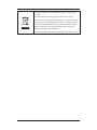
1
DPM Central Station Service Manual Intellectual Property Statement SHENZHEN MINDRAY BIO-MEDICAL ELECTRONICS CO., LTD. (hereinafter called Mindray) owns the intellectual property rights to this product and this manual. This manual may refer to information protected by copyrights or patents and does not convey any license under the patent rights of Mindray, nor the rights of others. Mindray does not assume any liability arising out of any infringements of patents or other rights of third parties. Mindray intends to maintain the contents of this manual as confidential information. Disclosure of the information in this manual in any manner whatsoever without the written permission of Mindray is strictly forbidden. Release, amendment, reproduction, distribution, rent, adaptation and translation of this manual in any manner whatsoever without the written permission of Mindray is strictly forbidden. , and are the registered trademarks or trademarks owned by Mindray in China and other countries. All other trademarks that appear in this manual are used only for editorial purposes without the intention of improperly using them. They are the property of their respective owners. Contents of this manual are subject to changes without prior notice. For this manual, the issued Date is 2015-02 (Version: 2.0). © 2013-2015 Shenzhen Mindray Bio-Medical Electronics Co., Ltd. All rights reserved NOTE z This manual describes all features and options. The equipment may not have all of them. Contact Mindray service department for any questions. DPM Central Station Service Manual I Manufacturer’s Responsibility Contents of this manual are subject to changes without prior notice. All information contained in this manual is believed to be correct. Mindray shall not be liable for errors contained herein nor for incidental or consequential damages in connection with the furnishing, performance, or use of this manual. Mindray is responsible for safety, reliability and performance of this product only in the condition that: All installation operations, expansions, changes, modifications and repairs of this product are conducted by Mindray authorized personnel; and The electrical installation of the relevant room complies with the applicable national and local requirements; and This product is operated under strict observance of this manual. Warranty This warranty is exclusive and is in lieu of all other warranties, expressed or implied, including warranties of merchantability or fitness for any particular purpose. Exemptions Mindray's obligation or liability under this warranty does not include any transportation or other charges or liability for direct, indirect or consequential damages or delay resulting from the improper use or application of the product or the use of parts or accessories not approved by Mindray or repairs by people other than Mindray authorized personnel. This warranty shall not extend to II Any Mindray product which has been subjected to misuse, negligence or accident; or Any Mindray product from which Mindray's original serial number tag or product identification markings have been altered or removed; or Any product of any other manufacturer. DPM Central Station Service Manual Return Policy In the event that it becomes necessary to return a unit to Mindray, follow the instructions below. 1. Obtain a return authorization. Contact the Mindray Service Department and obtain a Mindray Customer Service Authorization Number. The Mindray Customer Service Authorization Number must appear on the outside of the shipping container. Return shipments will not be accepted if the Mindray Customer Service Authorization Number is not clearly visible. Please provide the model number, serial number, and a brief description of the reason for return. 2. Freight policy The customer is responsible for freight charges when this product is shipped to Mindray for service (including any relevant customs fees or other freight related charges). 3. Return address Please send the part(s) or equipment to the address offered by Customer Service Department. DPM Central Station Service Manual III Contact Information Manufacturer: Shenzhen Mindray Bio-Medical Electronics Co., Ltd. Address: Mindray Building, Keji 12th Road South, Hi-tech Industrial Park, Nanshan, Shenzhen 518057 P.R. China Tel: +86 755 81888998 Fax: +86 755 26582680 Website: www.mindray.com Distributor: Mindray DS USA, Inc. Address: 800 MacArthur Boulevard Mahwah, New Jersey 07430 USA Tel: 1.800.288.2121, 1.201.995.8000 Website: www.mindray.com IV DPM Central Station Service Manual Contents 1 Safety ......................................................................................................................................... 1-1 1.1 Safety Information .......................................................................................................... 1-1 1.1.1 Dangers ................................................................................................................ 1-2 1.1.2 Warnings............................................................................................................... 1-2 1.1.3 Cautions ............................................................................................................... 1-2 1.1.4 Notes .................................................................................................................... 1-3 1.2 Equipment Symbols ........................................................................................................ 1-3 2 Introduction .............................................................................................................................. 2-1 2.1 Overview ......................................................................................................................... 2-1 2.2 Intellectual Property Protection....................................................................................... 2-1 2.3 Versions ........................................................................................................................... 2-2 3 System Installation ................................................................................................................... 3-1 3.1 Pre-installation Preparations ........................................................................................... 3-1 3.1.1 Environmental Requirements ............................................................................... 3-1 3.1.2 Power Requirements ............................................................................................ 3-1 3.2 Display Hardware Installation......................................................................................... 3-2 3.2.1 Double Screen Display Adapter ........................................................................... 3-2 3.2.2 Implementing Double Screen Display by DP-to-VGA Adapter........................... 3-3 3.2.3 Cancelling the Hot Keys ...................................................................................... 3-5 3.2.4 Setting My Main Display ..................................................................................... 3-6 3.2.5 Aligning the Double Screens ................................................................................ 3-7 3.2.6 Installing Multi-Screen Extend Device (SUNIX VGA2715) ............................... 3-8 3.2.7 Setting the Audio Properties................................................................................. 3-9 3.3 IP Address Setup and Network Connection .................................................................. 3-10 3.3.1 Network Connection Using Multiple Network Adapters ................................... 3-10 3.3.2 Monitor LAN ......................................................................................................3-11 3.3.3 External Network ............................................................................................... 3-15 3.4 Database Software Installation ...................................................................................... 3-16 3.5 Installation of the CS Software ..................................................................................... 3-18 3.5.1 Setting the Region and Language of the Operating System ............................... 3-18 3.5.2 Setting Operating System Time.......................................................................... 3-18 3.5.3 Setting User Account.......................................................................................... 3-19 3.5.4 Installing the CS System Software ..................................................................... 3-20 3.5.5 Initial Database Backup ..................................................................................... 3-24 3.6 Printer Installation ......................................................................................................... 3-25 3.6.1 Supported Printers .............................................................................................. 3-25 3.6.2 Printer Installation Procedures ........................................................................... 3-26 3.6.3 Tasks after Printer Installation ............................................................................ 3-31 3.7 Recorder Installation ..................................................................................................... 3-32 DPM Central Station Service Manual 1 4 About Telemetry Monitoring System (TMS) ......................................................................... 4-1 5 Software Upgrades ................................................................................................................... 5-1 5.1 Upgrading the CS Software ............................................................................................ 5-2 5.2 USB Dongle Compatibility ............................................................................................. 5-2 6 McAfee Solidcore S3 Control .................................................................................................. 6-1 6.1 Installation ....................................................................................................................... 6-1 6.2 Enabling the Solidifier .................................................................................................... 6-2 6.3 Adding or Editing Additional Applications ..................................................................... 6-3 7 System Recovery ...................................................................................................................... 7-1 7.1 Overview ......................................................................................................................... 7-1 7.2 HDD Replacement Procedure ......................................................................................... 7-1 7.2.1 Tools Required ..................................................................................................... 7-1 7.2.2 Replacing Both Hard Drives in a RAID Configured DPM CS ............................ 7-2 7.3 Database Backup ........................................................................................................... 7-12 7.4 Configuring Printer ....................................................................................................... 7-12 7.5 Installing Dual Displays ................................................................................................ 7-13 7.6 Installing Multiple Displays .......................................................................................... 7-13 7.7 Setting the Size of CS Screen........................................................................................ 7-13 7.8 Setting Language and Time ........................................................................................... 7-13 8 Maintenance and Cleaning ...................................................................................................... 8-1 8.1 Maintenance .................................................................................................................... 8-1 8.1.1 General Inspection ............................................................................................... 8-1 8.1.2 System Performance Test ..................................................................................... 8-2 8.2 Cleaning .......................................................................................................................... 8-2 9 Troubleshooting ........................................................................................................................ 9-1 9.1 The displaying text on the CS screen is abnormal. ......................................................... 9-1 9.2 Recorder/printer-related technical alarm messages ......................................................... 9-1 9.3 Network printing fails ..................................................................................................... 9-2 9.4 No waveform displayed in waveform review ................................................................. 9-2 9.5 Multi-/Dual-screen changes to Single-screen during the CS installation ........................ 9-2 9.6 Remove Dongle Error ..................................................................................................... 9-3 9.7 CS Unable to Connect the Bedside Monitor ................................................................... 9-3 9.8 Abnormal Database Service Handling ............................................................................ 9-4 9.9 Database Backup and Recovery in Case of System Failure ............................................ 9-4 2 DPM Central Station Service Manual 1 Safety 1.1 Safety Information DANGER z Indicates an imminent hazard situation that, if not avoided, will result in death or serious injury. WARNING z Indicates a potential hazard situation or unsafe practice that, if not avoided, could result in death or serious injury. CAUTION z Indicates a potential hazard or unsafe practice that, if not avoided, could result in minor personal injury or product/property damage. NOTE z Provides application tips or other useful information to ensure that you get the most from your product. DPM Central Station Service Manual 1-1 1.1.1 Dangers There are no dangers that refer to the product in general. Specific “Danger” statements may be given in the respective sections of this operation manual 1.1.2 Warnings WARNING z The device is intended for use only by clinical professionals or under their guidance. It must only be used by persons who have received adequate training in its use. Anyone unauthorized or untrained must not perform any operation on it. z The CS is a clinical information device. Except for using such components as the mouse and keyboard to perform normal operations, do not touch or disassemble any other component, especially the power component; otherwise, it may result in personnel injury. z Do not connect this system to outlets with the same circuit breakers and fuses that control current to devices such as life-support systems. If this system malfunctions and generates an overcurrent, or when there is an instantaneous current at power ON, the circuit breakers and fuses of the building’s supply circuit may be tripped. z Failure on the part of the responsible hospital or institution employing the use of the CS to implement a satisfactory maintenance schedule may cause undue equipment failure and possible health hazard. z Be sure to keep the packaging materials from children’s reach. Disposal of the packaging materials shall comply with your local requirements. 1.1.3 Cautions CAUTION z 1-2 Hospitals without stable power source should use an Uninterruptible Power Supply (UPS) to power the CS. When there is a power failure, the system should be shut down by following the specified shutdown procedure before the UPS is turned off. If the system has a sudden power failure, system failure may occur and consequently the system will not work correctly next time or even have a serious result. DPM Central Station Service Manual CAUTION z The host of the CS should be installed with the original Microsoft Windows’s system and standard upgrade program, such as the service package. Illegal software may lead to abnormal or incorrect system operating. z The host of the CS should be maintained every three to six months. Its long time continuous operating may lead to failure of the operating system. z Protect the device from damage caused by drop, impact, strong vibration or other mechanical force during servicing. 1.1.4 Notes NOTE z Refer to the Operator’s manual for more information. 1.2 Equipment Symbols Caution (Attention, consult accompanying documents) CAUTION: To reduce the risk of electric shock, do NOT remove cover. Refer servicing to qualified service personnel. Alternating current Power switch Keyboard port Mouse port DPM Central Station Service Manual 1-3 Serial communication˄COM˅port Display port Printer port USB port or device Network port Sound output port Sound input port Microphone port DATE OF MANUAFACTURE MANUFACTURER Serial number Equipotentiality 1-4 DPM Central Station Service Manual The following definition of the WEEE label applies to EU member states only. This symbol indicates that this product should not be treated as household waste. By ensuring that this product is disposed of correctly, you will help prevent bringing potential negative consequences to the environment and human health. For more detailed information with regard to returning and recycling this product, please consult the distributor from whom you purchased it. * For system products, this label may be attached to the main unit only. DPM Central Station Service Manual 1-5 FOR YOUR NOTES 1-6 DPM Central Station Service Manual 2 Introduction 2.1 Overview DPM Central Station (hereinafter called CS) is intended for professional physicians or paramedics to conduct centralized monitoring over patients monitored by Mindray individual monitors and/or telemetry systems in hospitals or medical institutions. The central station comprises powerful system software and high-performance computer. It constructs a monitoring network by connecting monitors and/or telemetry. By collecting, processing, analysing and outputting the information coming from monitors and/or telemetry, the central station can achieve centralized monitoring over multiple patients so as to greatly promote the efficiency and quality of the monitoring work. 2.2 Intellectual Property Protection The DPM Central Station uses a USB dongle for intellectual property protection. You must plug the dongle into the system’s USB interface before starting the system. Otherwise, the system cannot start. NOTE z When installing or using the CS, you must plug in the USB dongle. If the dongle is damaged or lost, you may need to reinstall the system software before using a new one. NOTE z When reinstalling the system software, try not to remove the old database so as to keep the old monitoring data. DPM Central Station Service Manual 2-1 2.3 Versions The CS system software, dongle and service manual versions correspond to each other as below. 2-2 CS System Software Dongle Service Manual 01.01.00 03.00.00 1.0 DPM Central Station Service Manual 3 System Installation 3.1 Pre-installation Preparations 3.1.1 Environmental Requirements The CS should be installed in an environment where the system can be easily viewed, operated and maintained. The environment where the CS is installed should be reasonably free from noises, vibration, dust, and corrosive, flammable and explosive substances. If the CS is installed in a cabinet, sufficient space in front and behind should be left for convenient operation, maintenance and repair. Moreover, to maintain good ventilation, the CS should be at least 2 inches (5cm) away from around the cabinet. When the CS is moved from one place to another, condensation may occur as a result of temperature or humidity difference. In this case, never start the system before the condensation disappears. 3.1.2 Power Requirements Each component of the CS must be powered by the specified power source. To protect the hospital personnel from electric shock, the CS (including the host and displays) and its recorder must have their casings properly grounded. The host of the CS is provided with a 3-wire power cable, which must be plugged into a properly grounded 3-wire receptacle. If a 3-wire, grounded receptacle is not available, consult the hospital electrician. WARNING z Make sure that the operating environment and power source of the CS meet the specific requirements; otherwise, unexpected consequences, e.g. damage to the equipment, may result. z Appropriate power supply must be selected according to the setup of the system power voltage; otherwise, serious damage may be caused to the system. z Never use a 3-wire to 2-wire adapter with any unit of the CS. DPM Central Station Service Manual 3-1 WARNING z The CS host cannot be installed with any other software besides the Windows system, necessary drivers, and drivers/software listed in this manual. Otherwise, normal operation of CS may be affected and unexpected consequences may result. NOTE z The CS software only supports Windows® 7 Professional Embedded SP1 operation system. z Before performing the operations described below, make sure that the main unit is not installed with any application software except the accompanying software of Windows. 3.2 Display Hardware Installation 3.2.1 Double Screen Display Adapter WARNING z Disconnect the power cord of the host before installing the PCI double screen display adapter. If it is necessary to install a double screen display adapter, do the following: 3-2 1. Install the double screen display adapter: Disconnect the power supply; insert the double screen display adapter into the PCI slot on the main board and then connect the primary and secondary display respectively to port 1 and port 2 of the double screen display adapter. 2. Install display adapter driver: Refer to the accompanying documents of the display adapter for details. Restart the computer after the display adapter driver has been installed. 3. Set double screen display mode: Refer to the accompanying documents of the display adapter for details. DPM Central Station Service Manual 3.2.2 Implementing Double Screen Display by DP-to-VGA Adapter The double screen display in the CS can be achieved by DP-to-VGA adapter: 1. Shut down the computer first. 2. Then connect two screens by DP-to-VGA adapter by referring to below HP8180: Connect display’s VGA cable Connect display’s VGA cable Connect DP port The plug has a spring 3. When the display is connected, power on the PC. 4. Right click the mouse on the desktop, and then select “Graphics Properties…” from the pop-up menu. 5. In the “Intel ® HD Graphics Control Panel” window, click “Display” Æ “Multiple Displays” to enter the “Multiple Displays” window, as shown in the following figure. DPM Central Station Service Manual 3-3 7 6 8 6. In the “Select Display Mode” field, select “Extended”. 7. In the “Select Active Displays” field, set the primary display to “Monitor ***”; set the second display to “Digital Display***”. “Monitor ***” refers to the display directly connecting the VGA interface of the PC. “Digital Display***” refers to the display connecting the VGA by DP-to-VGA adapter. 8. Click the “Apply” option. The “The new settings have been applied. Do you want to keep these settings?” message displays. 9. Click the “Yes” button to apply the setting. 10. Click the icon to close the window. NOTE z When unplugging the DP-to-VGA adapter, press the spring button on the DP plug and then unplug it downward. Failure to do so may damage the DP plug. The label beside DP port is: 3-4 . DPM Central Station Service Manual 3.2.3 Cancelling the Hot Keys To avoid the user error operation, follow the procedure to cancel the functional hot keys: 1. Enter the “Intel ® HD Graphics Control Panel” window, and then click the “Options” option to display the “Hot Key Manager” window, as shown in the following figure. 2 3 2. In the “Enable Hot Keys” field, click the “Off” option. 3. Click the “Apply” option to apply the setting. The “The new settings have been applied. Do you want to keep these settings?” message displays. 4. Click the “Yes” button to apply the setting. 5. Click the icon to close the window. DPM Central Station Service Manual 3-5 3.2.4 Setting My Main Display To make the desired screen as main display, follow this procedure: 1. Right click the mouse on the desktop, and then select “Screen resolution” from the pop-up menu to display the window, as shown in the following figure. 2 3 3-6 2. In the screens displaying list box, select the desired screen. 3. Select the “Make this my main display” option. 4. Click the “Apply” button to apply the setting. 5. Click the “OK” button to save the setting and close the window. DPM Central Station Service Manual 3.2.5 Aligning the Double Screens When the alignment between the screens is ragged, follow this procedure to align the screens at the same horizontal line: 1. Right click the mouse on the desktop, and then select “Screen resolution” from the pop-up menu to display the window, as shown in the following figure. 2. Click the screen signed with number 1 to select it, and then drag the screen down until the screen signed with number 1 aligns with the screen signed with number 2. 3. Click the “Apply” button to apply the setting. 4. Click the “OK” button to save the setting and close the window. You can refer the above steps to adjust the multi-screens alignment. DPM Central Station Service Manual 3-7 3.2.6 Installing Multi-Screen Extend Device (SUNIX VGA2715) 1. Take out the accompanying USB cable. Connect one end of the cable with the connector of SUNIX VGA2715, and the other end with the CS. 2. Place the SUNIX VGA2715 driver CD in the CS drive. Double click the driver in the CD and install by default configuration. The following icon will display in menu bar on the lower right corner of screen when installation is complete. VGA2715 icon 3. Connect the VGA cable of display with SUNIX VGA2715. Right click VGA2715 icon in the menu bar. When the CS are equipped with three or four displays, the following menu will pop up. Three Display Menu 3-8 Four Display Menu 4. Select the arrow to open the submenu. 5. Select the option of “Extend” in the corresponding submenu. Then the extension of the screen is done. 6. To adjust the display sequence, select the option of Advanced from the pop-up menu or sub-menu. The following Display Properties window will show. Set the sequence in the “Settings” tab. Click “Apply” to save your settings. DPM Central Station Service Manual Drag individual display icon to adjust display sequence. 3.2.7 Setting the Audio Properties 1. Right click Audio icon at the lower right corner of the screen, and then select the option of “Adjust Audio Properties”. The “Sounds and Audio Devices Properties” window will pop up. Select “Audio” tab, and then set default devices of “Sound playback” and “Sound recording” to the devices related to Realteck HD. 2. Restart PC when the above installation is done. Verify that the display effect meets the requirement. DPM Central Station Service Manual 3-9 3.3 IP Address Setup and Network Connection The PC will be equipped with two network adapters to isolate the monitor LAN and the external network to ensure network bandwidth and data safety for the monitors. NOTE z If two network adapters are used, be sure to identify which is for monitor network and which is for external network connecting multiple CSs, CS viewer or other information systems. Correctly set IP address for each network adapter. z If two network adapters are used, connect them to corresponding networks as desired. z Do not connect both network adapters to the same network segment, e.g., do not connect them to the monitor network at same time. 3.3.1 Network Connection Using Multiple Network Adapters The figure below shows the network connection using multiple network adapters. As shown in the figure, the two network adapters are respectively connected to the monitor LAN and the external network. 3-10 DPM Central Station Service Manual 3.3.2 Monitor LAN NOTE z If two network adapters are used, the one (hereinafter called integrated network adapter) integrated on the PC main board is normally connected to the monitor network and the one (hereinafter called independent network adapter) installed in the PCI slot is connected to the external network. z The default network adapter is the integrated network adapter, which is used for the patient network using CMS+ protocol only. z For CMS+ protocol, use IP address scheme 196.76.0.xxx and subnet mask 255.255.0.0. z Every IP Address on each individual network has to be unique. Duplicate IP Addresses will cause network connection failures. To set the IP addresses of the integrated network adapter: 1. Select the icon at the bottom of the screen to enter the following screen. Then click “Open Network and Sharing Center”. DPM Central Station Service Manual 3-11 3-12 2. In the pop-up screen, select “Change adapter settings”. 3. After accessing the Network Connection screen, right click “Local Area Connection”. 4. In the “Local Area Connection Properties” screen, double click “Internet Protocol version 4 (TCN/IPv4)”. DPM Central Station Service Manual 5. In the “Internet Protocol Version 4 (TCP/IPv4) Properties” screen, set an IP address (The address in the following figure is used for reference only). 6. If you need to configure more IP addresses, select “Advanced” (see the figure above), you will see the following screen display: DPM Central Station Service Manual 3-13 7. Click “Add…” in the “IP Settings”, and then you will see the following screen display: NOTE z 3-14 The subnet mask code for 196.76.0.1 must be 255.255.0.0. 8. Click “Add” to return to the following screen display. To add more IP addresses, repeat Step 7. 9. Click “OK” to finish setting IP address. DPM Central Station Service Manual 3.3.3 External Network The independent network adapter is used to connect the external network. Its IP address should be configured according to actual use. The external network is required when: Other information systems are connected; Patients of different CSs are viewed; Local CS is remotely viewed using a CS Viewer; Routers are used. IP Address Setup To implement the Remote CS function between CSs, each CS needs to be equipped with at least two network adapters, one of which is for internal communication within the current CS and the other for inter-communication between the CSs. The typical configuration is shown below: Current CS A Target CS B Target CS C Network adapter A1 Network adapter A2 Network adapter B1 Network adapter B2 Network adapter C1 Network adapter C2 196.76.0.X1 168.168.4.X2 196.76.0.Y1 168.168.4.Y2 196.76.0.Z1 168.168.4.Z2 As shown in the table above, network adapter A1, B1 and C1 are used for the communication between the CS and the monitors. Their IP addresses are in the same network segment with the IP addresses of respective monitors. Network adapter A2, B2 and C2 are used for the inter-communication between the CSs. Their IP addresses belong to the same network segment and X2, Y2 and Z2 shall be different. NOTE z If a CS needs to implement the Remote CS function on other CS, the IP address of other CS has to be added into the CS. Please refer to 12.2.8 Other - Multi-CMS Communication Settings in DPM Central Station Operator’s Manual for details (P/N 046-005011-00). DPM Central Station Service Manual 3-15 3.4 Database Software Installation Insert the CS software CD, then go to the directory “MySQL Community Server” and install by following the steps. 1. Double click MySQLInstall.exe, and the following “Choose Setup Language” screen will be displayed: 2. Select a desired language and click “Next” button till the following screen is shown: Since the data of database is saved under this directory, make sure that the disk in which the directory is located can read-write and provide enough space. When the selection is completed, click “Next” button until the following screen is shown: 3-16 DPM Central Station Service Manual 3. Complete installation and restart the PC When the following screen is shown, it indicates that the database software installation is complete. Select as the following screen shows and then click the “Finish” button. The computer will restart automatically. DPM Central Station Service Manual 3-17 3.5 Installation of the CS Software 3.5.1 Setting the Region and Language of the Operating System If the language used by the current operating system is the same language the user wants to display on the CS, it is unnecessary to set the region and language for the operating system. In this case, skip this step. If the language of the operating system is English but the user requires a non-English interface for the CS, it is necessary to set the region and language of the operating system. To set the region and language, follow this procedure: 1. Enter the Windows desktop and select “Start” Æ “Control Panel” Æ “Clock, Language, and Region” to enter the “Clock, Language, and Region” window. 2. Click the “Region and Language” option to display the “Region and Language” window. 3. Click the “Format” tab, and then select the desired language (locale) from the “Format” drop-down list. 4. Click the “Location” tab, and then select the desired language (locale) from the “Current location” drop-down list. 5. Click the “Administrative” tab, and then click the “Change system locale…” button to display the “Region and Language Settings” window. 6. Select the desired language (locale) from the “Current system locale” drop-down list. 7. Restart the computer to apply the setting. 3.5.2 Setting Operating System Time 3-18 1. Enter the Windows desktop and select “Start” Æ “Control Panel” Æ “Date and Time” to display the “Date and Time” window. The current tab displays the “Date and Time” tab. 2. Click the “Change time zone…” button to display the “Time Zone Settings” window. 3. Select the “Automatically adjust clock for Daylight Saving Time” option. 4. Click the “Internet Time” tab. 5. Click the “Change settings…” button to display the “Internet Time Settings” window. 6. Unselect the “Synchronize with an Internet time server” option. 7. Restart the computer to apply the setting. DPM Central Station Service Manual 3.5.3 Setting User Account You can select the CS system software (P/N G-110-002742-00) for DPM CS (300D). Before the installation, you must set the information notification to “Never Notify” according to the following steps: 1. Enter the Windows desktop and select “Start” Æ “Control Panel” to enter the “Control Panel” window. 2. Click “User Accounts and Family Safety” Æ “User Accounts” Æ “Change User Account Control settings” to display the “User Account Control Settings” window, as shown in the following Figure. 3. Drag down the slider to “Never notify”. 4. Click the “OK” button to complete the configuration. DPM Central Station Service Manual 3-19 3.5.4 Installing the CS System Software NOTE z Insert the USB dongle before installing the system software. z The software version of the USB dongle must match the version of CS. z Connect the network cable. The independent network adapter needs to connect to network. Refer to 3.3 IP Address Setup and Network Connection for additional information of independent network adapter. 1. In the CS software CD, double click “SETUP.EXE” under the “Setup” directory to enter the following window. NOTE 3-20 z The language selected as shown in the figure above is the one for display on the screen during the process of installation but not the default one when the CS is operating. The language used when the CS is operating is to be set up in the following steps. z Set OS language to English before installing CS system software in English or other language operating system. Change to the desired OS language after the installation. DPM Central Station Service Manual 2. Select language as the figure shows. Then click “OK” to enter installation procedure. During the installation, unless required, follow the default installation path, clicking “Next” until the following dialog box pops up. 3. Select a network adapter from “Net Adapter” (Usually the independent adapter is preferred.) and then select its IP address (191.168.0.1) from “IP Address”. Click “Next” until the following box pops up. (The displayed parameter will be automatically adjusted in the process.) NOTE z The setup screen of network IP address shown above can be displayed only when the integrated network card with the IP address 196.76.0.1 connects to network. DPM Central Station Service Manual 3-21 4. Select the desired language from the pop-up box and then click “OK” to enter the following window. 5. Enter hospital name and department name as required. Then click “OK”. 6. Select the desired installation type as per the following NOTE: NOTE 3-22 z Selecting “Create Database” will destroy the data in the database. “Create Database” is not required in the case of recovering to install CS software to save the previous data. “Create Database” is required when the CS software is installed for the first time. z Selecting “Update Database” will upgrade the data in the database. It is applicable to system software updating from old version to the latest version. Upgrading the database will back up the data in the current database automatically. If the database is already the latest version, the following box is displayed when “Update Database” is selected and “Next” is clicked. z Select "Don’t Create Database" if CS system software rather than database software is reinstalled and the current database file is compatible with the reinstalled system software. DPM Central Station Service Manual 7. Select the “Yes, I want to restart my computer now” radio button and click on “OK”. After restarting the computer, the CS will run automatically. DPM Central Station Service Manual 3-23 3.5.5 Initial Database Backup After the CS is installed, the database needs to be backed up. 3-24 1. Run the CS. Select “System Setup” Æ ”Admin Setup”(password: 111111)>“Others” ,then click “Database Backup and Recovery” to enter the following window. 2. Select “Database Backup” to enter the following window: 3. Select “Local Hard disk” and then “Next” to enter the following window. DPM Central Station Service Manual 4. Click “Start” to start to backup the database until the following window appears: 5. Click “Finish” to start the CS. NOTE z The above is initial database backup when the CS is installed. The database at that time does not contain any data. During actual maintenance, it may be necessary to backup database which has saved a large amount of data. If they are backed up onto the hard disk, the old backup will be deleted and only the latest are backed up. z When backing up database onto removable storage medium, make sure that the removable storage medium is not infected with virus. Perform virus scanning or formatting in advance. 3.6 Printer Installation 3.6.1 Supported Printers The CS supports the following printers: HP LaserJet M401n HP LaserJet M602 DPM Central Station Service Manual 3-25 3.6.2 Printer Installation Procedures Using the installation of HP LaserJet M602 as an example: Insert the printer driver CD into the CD-ROM Verifying the Printer IP: 1. Load the printer with paper and connect with the computer (connect to the integrated network card with IP address 196.76.0.X). 2. Power on the printer. The printer IP address information will be shown on the screen of the control panel as below: The printer IP 3. Verify this IP address is in the same network segment with the computer. If not, add a new computer TCP/IP address so that it is in the same network segment with the printer IP address. Adding TCP/IP 3-26 1. Enter the Windows desktop and select “Start” Æ “Control Panel” Æ “Network and Internet” Æ “Network and Sharing Center” Æ “Change adapter settings” to display the network connection window. 2. Double-click the “Local Area Connection” icon to display the “Local Area Connection Status” window. 3. Click the “Properties” button to display the “Local Area Connection Properties” window. 4. Select the desired device from the “This connection uses the following items” list box, and then click the “Properties” button to display the “Internet Protocol Version 4 (TCP/IPv4) Properties” window. DPM Central Station Service Manual 5. Select the “Use the following IPv4 address” option, and then click the “Advanced…” button to display the “Advanced TCP/IP Setting” window. 6. Select the “IP Settings” tab, and then click the “Add…” button to display the “TCP/IP Address” window. 7. Input an IP address that is in the same network segment with the printer IP address. Click the “Subnet mask” input box, the default subnet mask displays. 8. Click the “Add” button to add the IP and close the “TCP/IP Address” window. 9. Click the “OK” button to save the setting and close the “Advanced TCP/IP Setting” window. 10. Click the “OK” button to save the setting and close the “Internet Protocol Version 4 (TCP/IPv4) Properties” window. 11. Click the “OK” button to apply the setting and close the “Local Area Connection Properties” window. 12. Click the “Close” button to close the “Local Area Connection Status” window. Adding or Editing Additional Applications If applications have to be added, deleted or updated after the installation of Solidcore S3 Control, perform the following to enable the changes under the control of Solidcore: 1. Double click the icon of McAfee Solidifier Command Line on the desktop and the corresponding window will display. 2. Input "sadmin disable" in the command line, press the “Enter” key, and then restart the PC. The Solidcore control is disabled. You can add or delete the additional applications. 3. Double click the icon of McAfee Solidifier Command Line on the desktop, and then input "sadmin so" to scan all of applications. 4. Input “sadmin enable” in the command line, press the “Enter” key, and then restart the PC. Other commonly used commands of McAfee Solidifier include: sadmin help: used to view the commonly used commands; sadmin status: used to view the status of McAfee. DPM Central Station Service Manual 3-27 Installing the network printer 1. Insert the printer driver CD into the CD-ROM. 2. Right click the mouse to run CD driver, and then double click “setup.exe” file in the root directory. 3. Install the driver by following the indications shown below in the order of from left to right and from top to bottom: Accept the installation agreement. Input printer’s IP. When the test page is successfully printed, please click this button. 3-28 DPM Central Station Service Manual 4. After test page is printed, close all the pop-up windows and access “Printers and Faxes”. 5. Select “HP LaserJet 600 M601 M602 M603 PCL6” printer and re-name it as “M602_net” to complete installation of printer’s network driver. Adding or Editing Additional Applications If applications have to be added, deleted or updated after the installation of Solidcore S3 Control, perform the following to enable the changes under the control of Solidcore: 1. Double click the icon of McAfee Solidifier Command Line on the desktop and the corresponding window will display. 2. Input "sadmin disable" in the command line, press the “Enter” key, and then restart the PC. The Solidcore control is disabled. You can add or delete the additional applications. 3. Double click the icon of McAfee Solidifier Command Line on the desktop, and then input "sadmin so" to scan all of applications. 4. Input “sadmin enable” in the command line, press the “Enter” key, and then restart the PC. Other commonly used commands of McAfee Solidifier include: sadmin help: used to view the commonly used commands; sadmin status: used to view the status of McAfee. Installing the USB printer NOTE z Make sure that the USB cable of the printer is not connected with computer. 1. Right click the mouse to open CD driver, and then double click “setup.exe” file in the root directory. 2. Install the driver by following the indications shown below in the order of from left to right and from top to bottom: Accept the installation agreement. DPM Central Station Service Manual 3-29 When this page shows, connect USB. When the test page is successfully printed, please click this button. 3. After test page is printed, close all the pop up windows and access “Printers and Faxes” again. 4. Select “HP LaserJet 600 M601 M602 M603 PCL6” printer and re-name it as “M602_usb” to complete installation of printer’s USB driver. NOTE 3-30 z For HP LaserJet 2035n Printer, Double click the ‘Setup.exe’ which is in the driver CD root directory. Follow the installation guide and choose to install network driver or USB driver as needed. z When installing a printer, select to install network driver or USB driver based on the actual requirement. Connect the printer to the CS network if network printing is needed. DPM Central Station Service Manual 3.6.3 Tasks after Printer Installation To improve the print effect, follow the steps as below: 1. Enter the Windows desktop and select “Start” Æ “Control Panel” Æ “Hardware and Sound” Æ “Devices and Printers”. 2. In the “Printers and Faxes” field of the “Devices and Printers” window, select the desired printer and right click the printer. 3. Click the “Printer properties” option from the pop-up menu to display the printer properties window. 4. Click the “Advanced” tab. 5. Unselect the “Enable advanced printing features” option. 6. Click the “OK” button to apply the setting and close the printer properties window. To block the pop-up functional window when running the CS, follow the steps as below: 1. After install the printer, implement a printing task. A prompt window displays at the bottom-right of the desktop, as shown in the following figure. 2. Click the “Supplies Details” option to display the “Settings” window, as shown in the following figure. DPM Central Station Service Manual 3-31 3. Click the “Notification” tab, and unselect the “Enabled:” check box. 4. Click the “Offers” tab, and unselect the “Allow special device information and offers to be displayed” check box. 5. Click the “OK” button to apply the settings and close the “Settings” window. 3.7 Recorder Installation No recorder driver is needed. Recording can function directly after system software is installed. 3-32 DPM Central Station Service Manual 4 About Telemetry Monitoring System (TMS) The configurations about the TMS are operated at the central station (CS), such as programming the telemetry packs, admitting the transmitter, discharging the transmitter from the CS, refer to the TMS-6016 Telemetry Monitoring System Service Manual (P/N 046-005121-00). DPM Central Station Service Manual 4-1 FOR YOUR NOTES 4-2 DPM Central Station Service Manual 5 Software Upgrades NOTE z If the system on which the software is being updated is running the McAfee Solidcore Application, refer to section 6.3 Adding or Editing Additional Applications before continuing. z It is recommended to backup the database before software upgrading. Please refer to 3.5.5 Initial Database Backup for operation. z Exit the CS before performing software upgrade. If the original monitored data does not need to be stored, you can reinstall the CS software by following the instructions in Chapter Three and create a new database. If the original monitored data needs to be stored, you have to upgrade the database. z Do not power off or restart computer during the software upgrade process. This may lead to Software upgrade failure. NOTE z Restart the computer manually only after the setup files are installed. DPM Central Station Service Manual 5-1 5.1 Upgrading the CS Software Enter the Windows Operating System and go to “Start” Æ “Control Panel” Æ “Add or Remove Programs”. Choose “Central Station” and remove it. If the following dialogue box appears during uninstallation, check “Don’t display this message again” and then select “Yes”. Restart the computer after the system software is completely uninstalled. After restart, insert the CS system software CD and run the “setup.exe” file under the “Setup” directory. Refer to 3.5 Installation of the CS Software. 5.2 USB Dongle Compatibility The upgraded CS software is compatible with the original dongle. However, some newly added functions may not be disabled. 5-2 DPM Central Station Service Manual 6 McAfee Solidcore S3 Control 6.1 Installation For the CS with Solidcore S3 Control software (Optional), the installation of Solidcore S3 Controlwill be required. 1. Re-start the CS host, and access the CS screen. 2. Start “Windows Task Manager”, and then click the “Processes” tab. 3. End the “Master.exe” process, and then close the “Windows Task Manager” window to return the OS desktop. 4. Insert the McAfee Application Control Software CD (P/N: 115-012226-00) into the drive, and then select “SOLIDCOR510-6824_WIN” Æ “Setup-win2008-win7”. 5. In the “Setup-win2008-win7” folder, right click the “setup-win-7-x86-6.0.0.340” .exe file to display a pop-up menu. 6. Select the “Run as administrator” option to enter the Installation Wizard window. 7. Click the “Next” button. The “License Agreement” window displays. 8. Select the “I accept the terms in the license agreement” option, and then click the “Next” button. 9. In the “Customer Information” window, input the information as follows: User Name: input “cmsuser”. Organization: input “hospital” Serial Number: input the serial number listed on the Solidcore authorization label. (The Solidcore authorization label is located on the CD case of the CMS system software) 10. After input the information, click the “Next” button. 11. In the subsequent steps of the installation, the configurations are set by default. DPM Central Station Service Manual 6-1 6.2 Enabling the Solidifier 1. Once the installation is complete, double click the icon of McAfee Solidifier Command Line on the desktop. Then the following McAfee Command Line window displays. 2. Input “sadmin so” in the command line window, and press the “Enter” key. The computer performs solidification scan. 3. After the scan is done, input “sadmin enable” in the command line window, and press the “Enter” key. At this moment, a message indicates that Solidcore will run after the computer restarts. 4. Re-start the CS host after the above operations are finished. 5. Enter the CS screen, and then press the group keys “Ctrl+Alt+Del” to start “Windows Task Manager”. 6. Click the “Processes” tab, and then end the “Master.exe” process. 7. Close “Windows Task Manager”, and return to the OS desktop. 8. Double click the “McAfee Solidifier Command Line” icon on the desktop to access to the “McAfee Command Line” window. 9. Input the “sadmin status” to check whether the Solidcore is in the “Enabled” state or not, as shown in the following figure. Solidcore state 6-2 DPM Central Station Service Manual If the state is correct, it indicates that the installation is complete. WARNING z Ensure that the operating environment of CS is free from virus before the installation of Solidcore. Otherwise, the CS may break down after the installation of Solidcore. NOTE z The above-mentioned installation is required only when you select to install the software of Solidcore S3 Control. z Perform the installation of Solidcore S3 Control after other software is installed. 6.3 Adding or Editing Additional Applications If applications have to be added, deleted or updated after the installation of Solidcore S3 Control, perform the following to enable the changes under the control of Solidcore: 1. Double click the icon of McAfee Solidifier Command Line on the desktop and the corresponding window will display. 2. Input "sadmin disable" in the command line, press the “Enter” key, and then restart the PC. The Solidcore control is disabled. You can add or delete the additional applications. 3. Double click the icon of McAfee Solidifier Command Line on the desktop, and then input "sadmin so" to scan all of applications. 4. Input “sadmin enable” in the command line, press the “Enter” key, and then restart the PC. Other commonly used commands of McAfee Solidifier include: sadmin help: used to view the commonly used commands; sadmin status: used to view the status of McAfee. DPM Central Station Service Manual 6-3 FOR YOUR NOTES 6-4 DPM Central Station Service Manual 7 System Recovery 7.1 Overview The central station (CS) is installed in the dual hard disks computer. When one of the dual hard disks fails, replace the faulty disk with a new one. The new disk recovers automatically. When both hard disks fail, perform the following procedure: 7.2 HDD Replacement Procedure 7.2.1 Tools Required Software: 801-300B-00010-00 DPM-CS FRU HD IMAGE 300B-30-47716 DPM-CS SOFTWARE TOOLS 110-002742-00 DPM-CS SYSTEM SOFTWARE 115-012226-00 MCAFEE SOLIDCORE Hardware: Screw driver with TORX T15 Bit or large flat blade screwdriver. Replacement Hard Drive/s PN 0992-00-0287 Seagate 500 GB. NOTE z In a DPM CS RAID configuration both drives must be the exact same type. DPM Central Station Service Manual 7-1 7.2.2 Replacing Both Hard Drives in a RAID Configured DPM CS 1. Replace both Hard Drives. NOTE z 7-2 Drives must be of the same manufacture and size. 2. Turn on computer, then hit “ctrl-I” on the keyboard as the first screen appears to enter “Intel Rapid Storage Technology” Main Menu screen. 3. Select “Create RAID Volume”. (You will delete everything on the hard drives if they already have information stored on them.) 4. Accept “default name”, then select “RAID1 (Mirror)” for the RAID Level, and finally select “Create Volume”. 5. Plug the USB stick containing the Windows 7 HDD image (P/N 801-330B-00010-00), into the USB port on the front of the computer. 6. Exit the Intel® Rapid Storage Technology program, the system will go through its normal boot sequence. Press “F9” to access the Boot Menu. The system will ask for a password. Type in “Hypernet” (case sensitive) and press “Enter”. 7. Highlight “USB Device” using the up and down arrows and press enter. 8. After the DPM CS boots from the USB drive hit ok at the Symantec Ghost Splash Screen. This may take several minutes. 9. When the “About Symantec Ghost” prompt screen appears, click the “OK” dialog to proceed. DPM Central Station Service Manual 10. From the Symantec Ghost menu, select “Local” Æ “Disk” Æ “From Image”. 11. When the prompt opens, click on the “Look in:” dialog to select the corresponding USB drive which contains the ghost image. As an example, in the image below the files are located on the G Drive. 12. Select the WIN.GHO file located within the “HP 8380 RAID WIN 7” folder. Click on the WIN.GHO file to select the actual ghost file. DPM Central Station Service Manual 7-3 13. When prompted, select the destination drive to install the operating system which is the “Intel Raid” volume as shown in the figure below. 14. In the next screen, the dialog will show the destination drive details. Click “OK” to accept all default values. 15. Click “Yes” to acknowledge that the destination drive will be erased during the ghosting process. 16. Allow the ghosting process to complete. While the process is underway, the dialog window will show its progress from 0% to 100% as well as an estimated time remaining to complete the task. 7-4 DPM Central Station Service Manual 17. When the ghosting process is finished, click on “Continue” to close the “Clone Complete” dialog window. 18. Select “Quit” to exit from the Norton Ghost program. for confirmation to quit, click “Yes”. If a popup dialog windows asks 19. Unplug the USB stick containing the ghosting images from the front of the machine. 20. Restart the computer by holding down the power button to turn off the PC, and then turn it back on. Once the computer has restarted allow the computer to start normally and display the Windows desktop. 21. Click on the windows “Start” button at the lower left hand corner of the Window. Right click on the “Computer” menu and select “Properties”. In the dialog window that appears, click on the bottom of the window over the text “You must activate today. Activate Windows now.” 22. When prompted, type in the Windows Product ID from the label that is affixed to the top of the machine. 23. Use the phone system for activation. Follow the onscreen instructions for dialing the phone number and inputting the installation ID. Once the system validates the ID, type in the Confirmation ID. Follow the on screen instructions to finish the activation process. At the conclusion of activation, exit back to the Windows desktop. 24. Click on the Date and Time in the tray at the lower right hand corner of the screen. DPM Central Station Service Manual 7-5 25. Click on “Change Time and Date Settings…”. 26. Click on the “Internet Time” tab. 27. Click “Change Settings”. 7-6 DPM Central Station Service Manual 28. Uncheck the “Synchronize with an Internet time server” box. Then click “OK”. 29. From the “Date and Time” tab click on “Change time zone…”. 30. Uncheck the box labeled “Automatically adjust clock for Daylight Saving Time”. Then Click “OK”. 31. From the “Date and Time” menu, click “OK”. 32. Insert the CD containing the Software Tool (P/N 300B-30-47716). 33. Click and open the folder titled “USB Dog Driver”. Open the subfolders and double click on the “MicroDogInstdrv” application. The application installs the driver for the license dongle. DPM Central Station Service Manual 7-7 34. When the Micro Dog Driver installation window opens, select “USB Dog Driver” under Driver Installation. Finally click Install Driver button on the lower left hand side of the window. 35. When installation is complete, look for the message in red “The driver has been installed successfully”. Click “Exit” to exit from installation of the Micro Dog Driver. 36. From the same CD, click and open the “MySQL Community Server” folder”. Double click on the “MySQLInstall” application. Follow the on screen prompts to start the SQL installation. 37. Follow the prompts to install the SQL server. Select English as the default language. Accept the default installation location on the D Drive, D:\MySQLData\. 7-8 DPM Central Station Service Manual 38. When prompted, choose “Yes, I want to restart my computer now” and click “Finish”. 39. Connect an Ethernet cable between the LAN connection on the back of the computer and an Ethernet hub or switch. 40. From the Windows 7 desktop, click the “START” icon, Click “CONTROL PANEL”, Click “NETWORK AND SHARING CENTER”, click “CHANGE ADAPTER SETTINGS”. 41. Configure the “Local Area Connection 2” for static IP address with an address of 196.76.0.XXX and a subnet mask of 255.255.0.0. 42. Configure the “Local Area Connection” for static IP address with an address of 191.168.0.XXX and a subnet mask of 255.255.255.0. 43. Insert the DPM CS Software CD, 110-002742-00. Click to select and open the “CMSSetup” folder. Double click to open the “setup.exe” application to begin the installation process. 44. When prompted, select English as the default language. Also select the Ethernet port with the static IP address of 196.76.0.XXX as the patient network port. When prompted, select “Create Database”. DPM Central Station Service Manual 7-9 45. A “Create database, please wait…” message will appear. Creating the database will take a few minutes to complete. 46. ĀRestarting Windows” will open automatically. Highlight the “Yes, I want to restart my computer now” radio button, the computer will reboot automatically after “OK” is clicked. 47. Allow the machine to startup normally and acknowledge any prompts that appear. From the Central Station, click on “System Setup” then “Factory Setup”. Enter the password “63640802”. Select “Exit to Windows” to reach the Windows desktop. 48. Install the McAfee Solidifier. Insert the McAfee Solidcore Software CD (P/N 115-012226-00). Select and open the “Setup-win2008-win7” folder. Double click on the application “setup-win-7-x86-6.0.0.340.exe”. 49. Follow the on screen instructions to install the software to install the McAfee Solidifier Software. a. 7-10 Click “Next”. DPM Central Station Service Manual b. c. Click “I accept the terms in the license agreement” followed by “Next >”. Enter “MINDRAY” for both user name and organization. Type in the serial number, “0710-2208-1402-0108-2708”. Click “Next >” when complete. d. At The “Destination Folder” prompt, click on “Next >”. e. At the ‘Ready to Install the Program” prompt, click on “Install >”. f. Click “Finish” after the install is complete. g. Double click on the “McAfee Solidifier Command Line” shortcut on the desktop. h. In the command prompt, enter “sadmin so” command and press the “Enter” button. This process should take approximately ten minutes. i. Next enter the following commands and press the “Enter” button after each one. z Āsadmin enable” z Āsadmin updaters add gui.exe” DPM Central Station Service Manual 7-11 z Āsadmin updaters add translator.exe” z Āsadmin features disable mp” j. Restart the computer and exit to Windows desktop. k. Double click on the “McAfee Solidifier Command Line” shortcut on the desktop. l. Run the following command and press the “Enter” button after each one: z Āsadmin status” z Āsadmin updaters list” z For “sadmin status” command, the software should show “McAfee Solidifier” and “McAfee Solidifier on reboot” as both enabled. z For “sadmin updaters list” command, the software should show a list of programs and their statuses. 50. Restart Computer. From the CS program select “System Setup” Æ “Admin Setup” Æ enter “111111” Æ “Other” Æ “Database Backup and Recovery” to Restore the Database using the previously backed up .bak file, or manually configure all DPM CS settings and Peripheral Devices. Return system to service. NOTE z Do not recover the system with the method of recovery from hard disk if system failure is caused by other reasons. NOTE z System recovery will format disk C and disk D of the hard disk.So backup your desired data in disk C and disk D before performing the recovery operation. We assume no responsibility for loss of data during the recovery. 7.3 Database Backup Refer to section 3.5.5 Initial Database Backup. 7.4 Configuring Printer Refer to section 3.6 Printer Installation. 7-12 DPM Central Station Service Manual 7.5 Installing Dual Displays Refer to section 3.2.2 Implementing Double Screen Display by DP-to-VGA Adapter for dual displays connection and settings. 7.6 Installing Multiple Displays Refer to section 3.2.6 Installing Multi-Screen Extend Device (SUNIX VGA2715) for three or four displays connection and settings. 7.7 Setting the Size of CS Screen Access the CS system. Select “System Setup”Æ “Admin Setup” Æ “Screen Size”. Adjust the screen size of the CS system in accordance with actual screen size. Restart PC to enable the screen size settings. 7.8 Setting Language and Time Refer to section 3.5.1 Setting the Region and Language of the Operating System for language settings. Refer to section 3.5.2 Setting Operating System Time for time settings. DPM Central Station Service Manual 7-13 FOR YOUR NOTES 7-14 DPM Central Station Service Manual 8 Maintenance and Cleaning 8.1 Maintenance Failure on the part of the responsible hospital or institution employing the use of the central station to implement a satisfactory maintenance schedule may cause undue equipment failure and possible health hazard. WARNING z The safety checks or servicing involving any disassembly of devices should be performed by professional servicing personnel; otherwise, it may lead to undue equipment failure and possible health hazards. 8.1.1 General Inspection Whenever your system is repaired or upgraded, a thorough inspection should be performed by qualified service personnel to ensure the reliability. Before the central station is put into use and when it is in use, follow these guidelines to inspect it: Inspect the equipment and its accessories for mechanical damage; Inspect if the environment and power supply meet the specified requirements; Inspect all power cords and signal lines for fraying or other damages, and if they are properly connected and insulated; Inspect if the sound system functions normally; Inspect if each function of the system is in good condition; In case of any damage or abnormality, do not use the central station. Contact the hospital biomedical engineers or our service personnel immediately. DPM Central Station Service Manual 8-1 8.1.2 System Performance Test After the central station is reinstalled or quick recovery installation is performed, follow this procedure to make sure that the system functions correctly: Display setup Functional test of admitting patient Record and print Clear test data Shut down 8.2 Cleaning Your equipment should be cleaned on a regular basis. If the CS accumulates heavy dust, it should be cleaned regularly. The equipment to be cleaned includes the main unit (including power fan, cabinet fan or other fan etc.), displays, printer, recorder, keyboard and mouse. Before cleaning the equipment, consult your hospital’s regulations for cleaning, disinfecting and sterilizing equipment WARNING z Be sure to shut down the system and disconnect all power cords from the outlet before cleaning the equipment. z Cooling fans installed on CPU, display adapter and cabinet should be cleaned on a regular 6-months time interval. If any malfunction of cooling fan is encountered, please contact supplier for replacement as soon as possible. Dust accumulation on cooling fans can lead to failure due to high temperature. The exterior surfaces of the equipment may be cleaned with a clean and soft cloth, sponge or cotton ball, dampened with a non-erosive cleaning solution. Drying off excess cleaning solution before cleaning the equipment is recommended. Following are examples of cleaning solutions: 8-2 Hydrogen peroxide (3%) Ethyl alcohol (70%) Workstation/server cleaning solutions Liquid crystal display (LCD) detergent DPM Central Station Service Manual Follow these rules to clean the equipment; Failure to do so may cause the material to melt, distort, or may dull the finish of the case, blur lettering on the labels, or cause equipment failures. ALWAYS dilute the solutions according to the manufacturer’s suggestions. ALWAYS wipe off all the cleaning solution with a dry cloth after cleaning. NEVER SUBMERGE the equipment into water or any cleaning solution, or POUR or SPRAY water or any cleaning solution on the equipment. NEVER permit fluids to run into the casing, switches, connectors, or any ventilation openings in the equipment. NEVER use abrasive materials and erosive or acetone –based cleaners. WARNING z Disinfection or sterilization may cause damage to the equipment; therefore, when preparing to disinfect or sterilize the equipment, consult your hospital’s infection controllers or professionals. z The cleaning solutions above can only be used for general cleaning. If you use them to control infections, we shall assume no responsibility for the effectiveness. DPM Central Station Service Manual 8-3 FOR YOUR NOTES 8-4 DPM Central Station Service Manual 9 Troubleshooting 9.1 The displaying text on the CS screen is abnormal. Please ensure the region and language of the operating system is the same with the language set in the CS system. 1. To set up the region and language of the operating system, refer to section 3.5.1 Setting the Region and Language of the Operating System. 2. To set up the language of the CS, Click “System Setup” Æ “Admin Setup”Æ “Other” Æ “Language”and select the desired language. 9.2 Recorder/printer-related technical alarm messages Please refer to the Appendix B in “DPM Central Station Operator’s Manual”. When print fails, please follow the instruction to recover the print job: 1. Restart the printer. 2. Click the “System Setup” button and then select the “Printing Control” tab. 3. Click the button “Restart Print Service” to resume. 4. Select the relevant printer in “Printing Control” tab. Also, after the paper is loaded in the main input tray, push the tab close to the end of paper. DPM Central Station Service Manual 9-1 9.3 Network printing fails Follow the steps below: 1. Click “System Setup” button and then select “Printing Control” tab. Restart the print job. Try other printers in the printer list. If the problem still exists, go to the next step. 2. Check whether network printing works in Windows system. If it works, restart the computer, enter the CS and repeat step 1. If the problem still exists, go to the next step. 3. Verify the network cable between printer and CS host is operational. 4. Verify the printer’s IP address and CS host’s IP addresses are in the same network segment. Please refer to printer’s accompanying documents or ask the vendor’s customer service for the method of getting printer’s IP address. For example, for HP LaserJet 1505n, press the print button on the panel to print the configuration report which has IP address information. For HP LaserJet 2035n, press the print button on the panel for 5-10s to print the configuration report. 5. If the verification is Ok but the problem still exists, try to delete the printer driver and reinstall it by referring to section 3.6 Printer Installation. 6. If the problem still exists after driver installation, please contact the printer vendor’s customer service. 9.4 No waveform displayed in waveform review This symptom indicates that the user does not add the waveforms that need to be saved. To remove this fault, click in the patient window and then select “Display Setup” to enter the “Display Setup” tab sheet, select “Wave Save” and then add your desired waveforms. 9.5 Multi-/Dual-screen changes to Single-screen during the CS installation 9-2 1. Check if the displays are connected to host and work functionally. 2. Check if the display mode is set correctly; please refer to section 3.2.1 Double Screen Display Adapter, 3.2.2 Implementing Double Screen Display by DP-to-VGA Adapter or 3.2.6 Installing Multi-Screen Extend Device (SUNIX VGA2715). DPM Central Station Service Manual 9.6 Remove Dongle Error The following prompt message may appear during installation or running. Dongle error may be caused by dongle driver not installed, dongle inserted improperly, or USB port damaged. Please check dongle driver or reinsert dongle. 9.7 CS Unable to Connect the Bedside Monitor This fault may be caused by network configuration, network cable plugged improperly, network cable damaged etc. Refer to the following procedures to troubleshoot this fault. 1. Check if the network cable is plugged properly. 2. Check network configuration to see if the IP address of the CS and that or network bed number of the monitor are configured correctly. 3. Check if the firewall configuration is correct as the following picture. If not, continue with the following procedures. Use ping command to check if the CS can be connected to the bedside monitor. Try to ping as many monitors as possible. In the case of ping failure, the fault may lie in hardware. DPM Central Station Service Manual 9-3 Check if the crystal connector on the network cable or the network cable is damaged. 9.8 Abnormal Database Service Handling If database service stops by accident or runs abnormally, it will make the CS unable to normally save patient data. When this situation occurs, please try to restart the CS. If the high level system alarm disappears, it indicates that database service has been restored to normal storage status. If the high level system alarm persists, it indicates that database is severely damaged. In this case, you need to re-install database software. Please refer to section 3.4 Database Software Installation for detailed operation. 9.9 Database Backup and Recovery in Case of System Failure You can use the database backup and recovery tool to backup the current database and restore the database. For example, you should backup the current database before you replace the hard disk drive, reinstall the operating system or recover the CS using the mobile hard disk tool, and then restore the database after the operating system has been installed or the CS has been recovered. For database backup and recovery, refer to the operating manual. 9-4 DPM Central Station Service Manual P/N: 046-005114-00 (2.0)