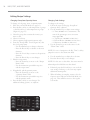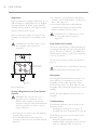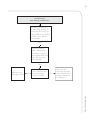
1
TM
Service Manual
for the turbochef ngo/sǒta
©2009-2014 TurboChef Technologies, Inc.
TM
rapid cook oven
For further information, call
800.90TURBO
or
+1 214.379.6000
The information contained in this manual is important for the proper installation, use, maintenance,
and repair of this oven. Follow these procedures and instructions to help ensure satisfactory baking
results and years of trouble-free service.
Errors – descriptive, typographic, or pictorial – are subject to correction. Specifications are subject to
change without notice.
Please carefully read this manual and retain it for future reference.
Table of Contents
Safety Instructions
General Safety Information
Reducing Fire Risk
Grounding Instructions
Power Cord Replacement
Precautions to be Observed Before and During Servicing to Avoid
Possible Exposure to Excessive Microwave Energy
RF Interference Considerations
i
i
ii
ii
ii
ii
Specifications and Installation
Theory of Operation
Dimensions
Certifications
Oven Construction
Electrical Specifications
Installation
Unpacking Instructions
Installation Warnings - Read Before Lifting Oven
Lifting and Placing the Oven
Installation Near Open Heat Source
Oven Connect Suite
Oven Connect
ChefComm Pro
ChefComm Limited
Voltage Selection
Ventilation
1
1
2
2
2
2
2
2
3
3
4
4
4
4
4
4
Daily Maintenance
5-6
Oven Controls and Cooking
Oven Controls
Cooking
Step 1: Turn the Oven On
Step 2: Select Cook Temperature
Step 3: Warming Up
Step 4: Soaking
Step 5: Ready to Cook
Step 6: Adjusting the Time
Step 7: Cooking
Step 8: Check/Remove Food from Oven
Step 9: Additional Cooking Options
Step 10: Cooling Down
7
8
8
8
8
9
9
9
9
10
10
10
Info, Test, and Edit Mode
Overview of the Info Mode
Viewing Cook Counter/Time Logs
Viewing the Fault Log
Viewing the Service Numbers
Setting the Language
F2 Bypass
Resetting the Oven
Set Options Screens
Network Setup
Auto On and Off: Setting the Time
Light Ring
Catalytic Recondition
Test Mode - Testing Oven Parts
Status Indicators
Turning Diagnostic Mode On/Off
Manufacturing Mode
Serial Number Edit
Changing Temperature Measurement Setting
Microwave Leakage Test (How to Use Oven for Testing)
Erase/Default Oven Settings
Updating the Oven Menu
Making a Copy of the Oven Menu
Updating the Oven Firmware
Menu Structure
Overview of the Edit Mode
Changing Set Temperatures
Edit Recipe Settings
Changing Group/Item/Quantity Name
Changing Cook Settings
11
11
11
11
11
12
12
12
12
13
13
13
14
14
14
15
15
15
15
15
16
16
17
17
17
17
18
18
18
Oven Systems
Convection System
Blower Motor (Bottom)
Blower Motor (Top)
Blower Motor Speed Controller (BMSC)
Heater Elements
Jetplate (Bottom)
Jetplate (Top)
Stirrer Motor and Assembly
Troubleshooting
Oven Door
Removing/Reinstalling the Oven Door
Adjusting the Oven Door
Interlock Switches
Adjusting the Primary, Secondary, and Monitor Switches
Measuring RF Leakage for Microwave Safety
Troubleshooting
19
19
19
19
19
19
19
19
19
20
20
20
21
21
22
22
Microwave System
Capacitors
Testing a Capacitor
Filament Transformers
Wiring the Filament Transformers
High-Voltage Transformers
Wiring the High-Voltage Transformers
Testing a Filament or High-Voltage Transformer
High-Voltage Diodes
Testing a High-Voltage Diode
Magnetrons
Testing a Magnetron for an Open/Shorted Filament
Stirrer Motor and Assembly
Waveguides
Troubleshooting
Control System
Control Board
Cooling Fans
Display
Electrical Compartment Cooling Fan Thermostat
Electrical Compartment Thermocouple
EMI Filter
Ethernet Extension Cable
Fuses
High-Limit Thermostat
Keypad
LED Light Ring (Sota only)
Magnetron Thermostats
Power Supply
Relay - K1 Filament
Relay - K2 Magnetron Cooling Fans
Relay - K3 Stirrer Motor
Relay - K6 Voltage
Relay - K7 Monitor
Relay - K8 Anode
RTD
Smart Card Reader
Solid State Relay - K4/K5 Heater
Speaker
Voltage Sensor
Wire Harness
Troubleshooting
Filtering System
Catalytic Converter
Air Filter
Vent Catalyst
Troubleshooting
23
23
23
23
23
24
24
24
24
25
26
26
26
26
26
27
27
27
27
27
27
27
28
28
28
28
28
28
28
28
28
28
28
29
29
29
29
29
29
29
29
29
30
30
30
30
30
Troubleshooting
Overview of Troubleshooting
Fault Code Descriptions
Fault Code Troubleshooting - F1 Blower Running Status Bad
Fault Code Troubleshooting - F2 Cook Temperature Low
Fault Code Troubleshooting - F3 Magnetron Current Low
Fault Code Troubleshooting - F4 Door Monitor Defective
Fault Code Troubleshooting - F5 Magnetron Over Temperature
Fault Code Troubleshooting - F6 Electrical Compartment Temperature High
Fault Code Troubleshooting - F7 RTD Open
Fault Code Troubleshooting - F8 Heat Low
Fault Code Troubleshooting - F9 Cook Cavity Temperature High
Non-Fault Code Troubleshooting - No Keypad Input
Non-Fault Code Troubleshooting - “Cook Door Open” Message when Door is Closed
Non-Fault Code Troubleshooting - No Display (Screen is Blank)
Non-Fault Code Troubleshooting - Food Not Cooking Properly
Non-Fault Code Troubleshooting - “Read Fail” Message when Loading a Menu
Non-Fault Code Troubleshooting - “Write Fail” Message when Loading a Menu
Non-Fault Code Troubleshooting - Menu Settings are Not Present
Non-Fault Code Troubleshooting - “Defective Media” Message When Oven is
Plugged in or Restarted
31
31
33
34
35
36
36
37
37
38
38
39
39
40
41
42
42
43
Oven Schematic
45
44
Appendix - Replacing Oven Components
Replacing Oven Components
Replacing Items - No Cover Removal Required
Replacing Items - Removing Outer Shell Required
Replacing Items - Removing Outer Shell and Back Cover Required
Replacing Items - Removing Outer Shell and Back Cover Required,
Single Magnetron Sota
A-1
A-2
A-4
A-11
A-12
i
IMPORTANT SAFETY INSTRUCTIONS
WARNING: When operating this oven, strictly adhere to the following safety precautions to reduce the risk
of burns, electric shock, fire, injury, damage to oven or property near oven, or possible exposure to excessive
microwave energy.
General Safety Information
DRead all instructions before using this appliance.
DRead and follow the specific “Precautions to be Observed Before and During Servicing to Avoid Possible
Exposure to Excessive Microwave Energy” found on page ii.
DThis appliance must be grounded. Connect only to a properly grounded outlet. See “Grounding
Instructions” on page ii.
DInstall or locate this appliance only in accordance with the provided installation instructions.
DThis appliance should be serviced by qualified service personnel only. Contact the nearest authorized
service facility for examination, repair, or adjustment.
DKeep the cord away from heated surfaces.
DLiquids, such as water, coffee, or tea are able to be overheated beyond the boiling point without
appearing to be boiling. Visible bubbling or boiling when the container is removed from the microwave
oven is not always present. this could result in very hot liquid suddenly boiling over when
the container is disturbed or a utensil is inserted into the liquid.
Dwarning: The contents of feeding bottles and baby food jars must be stirred or shaken and the
temperature checked before consumption, in order to avoid burns (IEC 60335-2-90)
DUse this appliance only for its intended uses as described in this manual.
DOnly use utensils that are suitable for use in microwave ovens (IEC 60335-2-90)
X do not use corrosive chemicals or vapors in this appliance; it is not designed for industrial/laboratory use.
X warning: do not heat liquids or other foods in sealed containers (e.g., jars, whole eggs, etc.) since
they are liable to explode.
X do not cook with metal lids or aluminum foil
X do not cook without food in the cook cavity.
X do not allow children to use this appliance.
X do not operate this appliance if it has a damaged cord or plug, is not working properly, or has been
damaged or dropped. See “Power Cord Replacement” found on page ii.
X do not cover or block any openings on this appliance.
X do not store this appliance outdoors.
X do not use this product near water (e.g., near a kitchen sink, in a wet basement, near a swimming pool).
X do not immerse the cord or plug in water.
X do not let the cord hang over the edge of a table or counter.
X do not use a water jet for cleaning. See pages 5-6 in this manual for proper cleaning procedures.
X This appliance is not to be used by children or persons with reduced physical, sensory or mental
capabilities, or lack of experience and knowledge, unless they have been given supervision or instruction.
DRemove wire twist-ties from paper or plastic bags used to facilitate cooking in the oven.
DIf materials inside the oven ignite, keep the oven door closed, turn the oven off, and disconnect the
power cord or shut off power at the fuse or circuit breaker panel.
DIf smoke is observed, switch off or unplug the oven. Keep the door closed to stifle any flames.
X
X
X
do not use the cook cavity for storage purposes.
do not overcook food. Carefully attend to the oven if paper, plastic, or other combustible materials are
placed inside the oven to facilitate cooking.
do not leave paper products, cooking utensils, or food in the cavity when the oven is not in use.
save these instructions
SAFETY INSTRUCTIONS
Reducing Fire Risk
ii
SAFETY INSTRUCTIONS
Grounding Instructions
This appliance must be grounded. In the event of an electrical short circuit, grounding reduces the risk of
electric shock by providing an escape wire for the electric current. This oven is equipped with a cord that has
a grounding wire with a grounding plug, which must be plugged into an outlet that is properly installed and
grounded. Consult a qualified electrician or serviceman if uncertain about the ability to follow grounding
instructions or if doubt exists as to whether the appliance is properly grounded.
X
do not use an extension cord. If the power cord is too short, have a qualified electrician or
serviceman install an outlet near the appliance.
WARNING: Improper grounding can result in risk of electric shock.
Power Cord Replacement
If the power cord is damaged, it must be replaced by the manufacturer, its service agent, or a similarly
qualified person.
Precautions to be Observed Before and During Servicing to Avoid Possible
Exposure to Excessive Microwave Energy
(a) do not operate or allow the oven to be operated with the door open.
(b) Make the following safety checks on all ovens to be serviced before activating the magnetron or other
microwave source, and make repairs as necessary: (1) interlock operation, (2) proper door closing,
(3) seal and sealing surfaces (arcing, wear, and other damage), (4) damage to or loosening of hinges
and latches, (5) evidence of dropping or abuse.
(c) Before turning on microwave power for any service test or inspection within the microwave
generating compartments, check the magnetron, wave guide or transmission line, and cavity for
proper alignment, integrity, and connections.
(d) Any defective or misadjusted components in the interlock, monitor, door seal, and microwave
generation and transmission systems shall be repaired, replaced, or adjusted by procedures described
in this manual before the oven is released to the owner.
(e) A microwave leakage check to verify compliance with the Federal Performance Standard should be
performed on each oven prior to release to the owner.
Refer to page 22 for leakage test procedures.
RF Interference Considerations
The NGO oven generates radio frequency signals. This device has been tested and was determined to be in
compliance with applicable portions of FCC part 18 requirements and to the protection requirements of
Council Directive 89/336/EEC on the approximation of the laws of the Member States relating to electromagnetic compatibility at the time of manufacture. However, some equipment with sensitivity to signals
below these limits may experience interference.
If your equipment experiences interference:
DIncrease the physical separation between this oven and the sensitive equipment.
DIf the sensitive device can be grounded, do so following accepted grounding practices.
DIf battery-powered microphones are being affected, ensure that the batteries are fully charged.
DKeep sensitive equipment on separate electrical circuits if possible.
DRoute intercom wires, microphone wires, speaker cables, etc. away from the oven.
1
2.5”
(64 mm)
16.0”
(406 mm)
25.0”
(635 mm)
25.9”
(658 mm)
10.7”
(272 mm)
21.0”
(533 mm)
4.0”
(102 mm)
11.8”
(300 mm)
39.1”
(993 mm)
2.5”
(64 mm)
27.3”
(693 mm)
Approximate location
of cord and plug
18.5”
(470 mm)
4.2”
(107 mm)
Figure 1: NGO Oven Dimensions
Dimensions
Utilizing TurboChef’s patented technology to
rapidly cook food without compromising quality,
the NGO oven provides superior cooking
performance while requiring minimal space and
energy consumption. The control system precisely
coordinates independent top and bottom impinged
airflow with top-launched microwave to deliver
product-specific results, and integral catalytic
converters allow for UL®-certified ventless
operation (see page 4 for details).
Oven Dimensions
Height: 25.0” (635 mm)
Width: 16.0” (406 mm)
Depth (footprint): 18.5” (470 mm)
Depth (door closed): 29.8” (757 mm)
Depth (door open): 39.1” (993 mm)
Weight, Sota: 170 lb. (77 kg)
Weight, Single Magnetron Sota: 135 lb. (61.2 kg)
This manual includes instructions for installing,
cleaning, operating, and servicing the NGO oven.
If you have questions that are not addressed in this
manual, contact Customer Support at
800.90TURBO (+1 214.379.6000) or your
Authorized Distributor.
Cook Cavity Dimensions
Height: 7.2” (183 mm)
Width: 12.5” (318 mm)
Depth: 10.5” (267 mm)
Volume: 0.54 ft (15.4 liters)
3
Clearances
Top: 5” (127 mm)
Sides: 2” (51 mm)
SPECIFICATIONS AND INSTALLATION
Theory of Operation
2
SPECIFICATIONS AND INSTALLATION
Certifications
cULus, UL EPH, TÜV, CE, FDA
* US/Canada models include a voltage sensor
that detects 208 or 240 VAC, but does not compensate for lack-of or over-voltage installations.
Installation
Install or locate this appliance only in accordance
with the instructions below.
Oven Construction
Exterior
- Two-tone stainless steel front, top, and sides
- Ergonomic door handle
- 4” (102 mm) adjustable legs
- Cool-to-the-touch door with microwave seal
Interior
- 304 stainless steel interior
- Fully-insulated cook chamber
- Removable rack
- Top and bottom jetplates
Electrical Specifications
TurboChef recommends a Type D circuit breaker
for all installations outside the United States.
Single Phase (6200 watts)
US/Canada: 208/240 VAC*, 60 Hz, 30 A
Europe/Asia (UK): 230 VAC, 50 Hz, 27 A
Brazil (BK): 220 VAC, 60 Hz, 28 A
Latin America (LA): 220 VAC, 60 Hz, 28 A
Japan (JK): 200 VAC, 50 or 60 Hz, 30 A
Multiphase (6200 watts)
Europe/Asia Wye (EW): 400 VAC, 50 Hz, 16 A
Europe/Asia Delta (ED): 230 VAC, 50 Hz, 20 A
Japan Delta (JD): 200 VAC, 50 or 60 Hz, 20 A
Korea/Middle East Wye (KW): 400 VAC, 60 Hz, 16 A
Korea/Middle East Delta (SD): 230 VAC, 60 Hz, 20 A
Australia (AU): 400 VAC, 50 Hz, 16 A
Single Magnetron
US/Canada 1 Ph: 208/240 VAC*, 60 Hz, 20 A, 4.2/4.8 kW
Europe (UK) 1 Ph: 230 VAC, 50 Hz, 13 A, 3 kW
Europe (UK) 1 Ph: 230 VAC, 50 Hz, 16 A, 3.6 kW
Unpacking Instructions
1. Remove the oven from its packaging.
2. Before discarding, check the packaging
thoroughly for accessories and literature.
NOTE: Packaging may also be retained in case the
oven may at some point be shipped somewhere
else or returned to the manufacturer.
3. Check the cook cavity thoroughly for
accessories and literature.
4. Discard any packaging in the cook cavity.
Installation Warnings - Read Before Lifting Oven
WARNING: The Sota oven weighs
approximately 170 lb. (77 kg). The Single
Magnetron Sota oven weighs approximately
135 lb. (61.2 kg). Never lift with fewer than
two people.
WARNING: Never lift the oven from the
front and rear or by the door handle. Doing so
will cause the door to misalign, resulting in a
non-warranty service call.
WARNING: The oven must be properly
placed on a food station at all times.
TurboChef will not recognize a fallen oven as
a warrantable claim and is not liable for any
injuries that may result.
WARNING: This oven is not intended for
built-in installation (i.e., installing the oven in
any structure that surrounds the oven by five
or more sides). Be sure to provide a minimum
of 2” (51 mm) clearance for all sides and 5”
(127 mm) clearance for the top.
WARNING: This oven is not intended to be
stacked without appropriate hardware.
Contact TurboChef for details.
3
Lifting and Placing the Oven
1. Prepare a surface at least 26” (660 mm) deep
and capable of supporting 175 lb. (79 kg).
NOTE: Do not remove the oven legs, as clearance
is required for the bottom cooling fan.
2. Position one or more persons at the left and
right sides of the oven.
3. Place hands under the oven and lift.
4. Place the oven on the prepared surface,
ensuring no edges are hanging off the sides.
5. Ensure the oven rack is properly installed
(attached to the bottom jetplate).
6. Plug in the oven.
NOTE: The oven is primarily serviced through its
top. DO NOT install shelving directly over the
unit. The operator will be responsible for service
charges incurred as a result of added time required
to access the top of the oven.
Installation Near Open Heat Source
When placing a TurboChef oven near an open
heat source (Figure 2), strictly adhere to the following:
- If the oven is being placed near a grill or stove,
a divider must exist between the oven and the
open heat source, with a minimum of 6” (152
mm) between the oven and the divider.
- If the oven is being placed near a fryer, a
divider must exist between the oven and fryer,
with a minimum of 12” (305 mm) between
the oven and the divider.
- The height of the divider must be greater than
or equal to the height of the oven (25.0” or
635 mm).
- Verify the oven location has a minimum 5”
(127 mm) clearance on top and a minimum 2”
(51 mm) clearance on each side.
Counter Top / Table
Partition
25.0” (635 mm)
Above Counter Top
Partition
25.0” (635 mm)
Above Counter Top
Deep Fryer
6”
(152 mm)
Minimum
Figure 2: Installation Near Open Heat Source
12”
(305 mm)
Minimum
SPECIFICATIONS AND INSTALLATION
TurboChef
NGO Oven
Grill
4
SPECIFICATIONS AND INSTALLATION
Oven Connect Suite
Oven Connect
Oven ConnectTM allows you to update menu
settings for multiple ovens at once, from one
central location. Oven Connect can also download
oven diagnostics and counters. For more information on how to network ovens, see page 12. For
information on obtaining Oven Connect, contact
TurboChef Customer Support at 800.90TURBO
or +1 214.379.6000.
If servicing a control board, follow the instructions
on page 27 to ensure proper connectivity.
Voltage Selection
For North America oven models, the oven will
detect 208 or 240 incoming voltage.
The initial voltage selection is typically completed
before the oven is used by the customer. However,
if incoming voltage for the store is different than
the preset voltage, the operator will be required to
select either 208 or 240 after pressing the On/Off
key to turn on the oven. The correct voltage will be
enlarged on the screen, identifying which option to
select (see Figure 3 below).
SELECT VOLTAGE:
ChefComm Pro
208 VAC
Part Number: CON-7006
240 VAC
ChefComm Pro® empowers any user of a
TurboChef oven to easily create menu settings
on a computer and transfer them to an oven via
smart card. For more information, call TurboChef
Customer Support at 800.90TURBO or
+1 214.379.6000.
ChefComm Limited
Part Number: CON-7016
ChefComm LimitedTM is a “read-and-transfer only”
version of ChefComm Pro that helps ensure
carefully-crafted settings are easy to distribute
globally, while providing the peace of mind that
they will not be altered.
Figure 3: Selecting Voltage
Ventilation
The TurboChef TurboChef Sǒta (model NGO)
oven has been approved by Underwriter’s
Laboratory for ventless operation (UL KNLZ listing) for all food items except for foods classified as
“fatty raw proteins.” Such foods include bone-in,
skin-on chicken, raw ham¬burger meat, raw bacon,
raw sausage, steaks, etc. If cooking these types of
foods, consult local HVAC codes and authorities to
ensure compliance with ventilation requirements.
To ensure continued compliance with all health,
building, and fire codes, you are required to maintain clean and sanitary conditions around your
oven at all times.
NOTE: In no event shall the manufacturer assume
any liability for damages or injuries resulting from
installations which are not in compliance with the
instructions and codes previously listed. Failure to
comply with these instructions could result in the
issuance of a temporary cease and desist order from
the local health department until the environment
concerns are addressed.
5
Daily Maintenance
Supplies and Equipment
Follow the steps below when cleaning your NGO
oven. Use only TurboChef ®-approved cleaning
chemicals. The use of any other cleaning products
may damage critical oven components, resulting in a
non-warranty service call.
TurboChef ® Oven Cleaner (Product Number:
103180), TurboChef ® Oven Guard (Product Number:
103181, optional for easier maintenance), Kay ClickSan® sanitizer, nylon scrub pad, cleaning towel, disposable gloves, protective eyewear, dust mask (optional)
Step 1: Prepare the Oven
WARNING: The oven operates at approximately 525°F (274°C) and may
cause injury if not allowed to cool properly.
t5VSOPGGUIFPWFOCZQSFTTJOHUIF0O0GGLFZ
t4MJHIUMZPQFOUIFPWFOEPPS
Step 1
t$PPMJOHUBLFTBQQSPYJNBUFMZNJOVUFTDO NOT clean the oven until the
oven displays oven off: ready to clean.
Step 2: Remove the Wire Rack and Lower Jetplate
WARNING: Be sure the oven interior is cool before removing these items.
Step 2 (Fig A)
CAUTION: Do not force the rack out by pulling upward. Forcefully
dislodging the rack could cause the top ceramic jetplate to break.
t5IFXJSFSBDLBOEMPXFSKFUQMBUFBSFDPOOFDUFEBOEDBOCFSFNPWFEUPHFUIFS
t1VTIUIFXJSFSBDLUPXBSETUIFSFBSDBWJUZXBMM'JH"
BOEUIFOMJGUVQ'JH#
t.BOFVWFSUIFCPUUPNKFUQMBUFPVUGSPNVOEFSUIFUBCTPOUIFSFBSDBWJUZXBMM
Step 2 (Fig B)
CAUTION: DO NOT remove the top ceramic jetplate; breakage will result in
a non-warranty service call.
Step 3: Clean the Wire Rack and Lower Jetplate
t%FUBDIUIFXJSFSBDLGSPNUIFKFUQMBUFBOEXBTISJOTFTBOJUJ[FBOEESZFBDIQBSU
Step 4: Clean the Air Filter
Step 4
t3JOTFUIFBJSGJMUFSXJUIIPUXBUFS
t"MMPXUIFBJSGJMUFSUPESZDPNQMFUFMZ
Step 5
CAUTION: DO NOT operate the oven without the air filter in place.
Step 5: Wipe the Oven Interior
t6TFBGPPEWBDVVNPSEBNQUPXFMUPSFNPWFMBSHFQBSUJDMFTGSPNUIFPWFODBWJUZ
Continued on page 6.
DAILY MAINTENANCE
CAUTION: TurboChef does not recognize blocked air vents as a warrantable
claim. The filter must be cleaned regularly or replaced if damaged. During oven
operation, the filter must remain in place at all times.
t3FNPWFUIFBJSGJMUFSGSPNUIFCBDLPGUIFPWFO
6
DAILY MAINTENANCE
Step 6: Clean the Oven Interior
t4QSBZ5VSCP$IFG¥0WFO$MFBOFSPOUPUIFUPQCPUUPNBOETJEFTPGPWFOJOUFSJPS
CAUTION: DO NOT spray Oven Cleaner into the holes on the back oven
wall. Doing so can damage critical oven components, resulting in a nonwarranty service call.
Step 6 (Fig A)
Upper
jetplate
Step 6 (Fig B)
t"MMPX0WFO$MFBOFSUPQFOFUSBUFTUBJOTGPSGJWFNJOVUFT
t$MFBOUIFPWFOJOUFSJPSXJUIBOZMPOTDSVCQBE
CAUTION: DO NOT attempt to scrub the upper jetplate (Fig B). If food is
stuck to the oven ceiling, gently remove it without applying pressure to the
ceramic plate. Breakage will result in a non-warranty service call.
CAUTION: DO NOT remove the top ceramic jetplate (A); breakage will result
in a non-warranty service call.
Step 7: Clean and Dry the Oven Door
t$MFBOUIFPWFOEPPSXJUI0WFO$MFBOFSBOEBOZMPOTDSVCQBE
t8JQFUIFPWFOEPPSXJUIBEBNQUPXFMBOEUIFOBESZUPXFM
Step 8: Rinse or Wipe the Oven Interior
Step 7
Step 8
CAUTION: DO NOT use a hose or water jet for cleaning. Doing so can damage
critical oven components, resulting in a non-warranty service call.
t8JQFEPXOUIFPWFOJOUFSJPSXJUIBDMFBOEBNQUPXFM
t%SZUIFPWFOJOUFSJPSXJUIBDMFBOUPXFM
Step 9: Apply TurboChef® Oven Guard - Optional for Easier Maintenance
t4QSBZ5VSCP$IFG¥0WFO(VBSEPOUPBDMFBOUPXFM
t8JQFUIFJOUFSJPSXBMMTBOEUIFJOTJEFPGUIFPWFOEPPS
CAUTION: DO NOT spray Oven Guard into the cavity, especially around the
holes on the back oven wall. Doing so can damage critical oven components,
resulting in a non-warranty service call.
Step 9
Step 10
Step 11
Step 10: Reinstall Components
t3FDPOOFDUUIFXJSFSBDLUPUIFMPXFSKFUQMBUFBOESFJOTUBMMCPUIJUFNT
t$MPTFUIFPWFOEPPS
t3FJOTUBMMUIFGJMUFSPSSFQMBDFJUXJUIBOFXPOFJGUIFNFTIJTEFUFSJPSBUFEIBT
large openings, or has started to dislodge from the frame.
Step 11: Clean the Oven Exterior
t8JQFUIFPWFOFYUFSJPSXJUIBDMFBOEBNQUPXFM
t3FNPWFUIFMPXFSQBOFMBOESFNPWFMBSHFGPPEQBSUJDMFT
t8JQFUIFQBOFMXJUIBDMFBOEBNQUPXFM
CAUTION: DO NOT spray chemicals into any openings, such as the louvers on
the side panels or the rear vent catalyst housing. Doing so can damage critical
oven components, resulting in a non-warranty service call.
t5IFPWFOJTSFBEZUPUVSOPO
7
8
7
7
1
2
3
4
5
6
Figure 4: Oven Controls
Oven Controls
1. On/Off Key
Press to turn the oven on (begin warmup) or off
(cool down), or to exit Info Mode (page 11).
2. Info Key
When the oven is off or cooling down, press to
access the Info Mode (page 11).
3. Up and Down Keys
When the oven is ready to cook (i.e., warmed up
and waiting for a cook command), press the Up or
Down key to view additional food groups or items.
When the oven is in the Info Mode (page 11),
press to navigate between screens 1 and 2.
4. Display
The display shows information relevant to the
current oven operation and/or user options.
5. Back/Stop Key
When the oven is cooking, press the Back/Stop key
to immediately terminate a cook cycle.
6. Enter Key
Press the Enter key when saving changes to food
item settings (Figure 26, page 18), or whenever
instructed by the oven screen.
7. Soft Keys
There are eight soft keys - four to the left and right
of the display. Press a soft key to select an option
adjacent to that key on the display.
NOTE: Soft keys are labeled L1-L4 and R1-R4 in
this manual (where applicable) for easier identification and reference.
8. Numeric Keypad
Use the numeric keypad to enter access passwords
or modify cook settings (Figure 26, page 18). The
numeric keypad also contains a Back/Stop key and
an Enter key, which are functionally identical to
Items 5 and 6.
OVEN CONTROLS AND COOKING
When editing a food item, press to navigate
between editable fields (Figure 26, page 18).
When the oven is ready to cook (i.e., warmed up
and waiting for a cook command), or in the Info
Mode (page 11), press the Back/Stop key to return
to the previous screen.
8
OVEN CONTROLS AND COOKING
Cooking
The oven is preprogrammed with recipe settings at the time of manufacture and is ready to operate out of the
box. If these settings are erased, new menu settings must be either loaded via Oven Connect (page 4), smart
card (page 16), or programmed manually (pages 17-18). The oven will not cook unless settings are present.
Note that the steps below are not always sequential. Typically, multiple items are cooked before cooling the
oven (Step 10).
Step 1: Turn the Oven On
TURBOCHEF NGO
OVEN OFF
When the oven is off (Figure 5), the oven temperature has
receded below 150°F (66°C), but the display and keypad
remain on.
R EA DY TO C LEA N
Press the On/Off key to turn the oven on.
Figure 5: Oven Off
Step 2: Select Cook Temperature
SELEC T COO K T EM P ER AT U R E
T EM P 1: 500F
T EM P 2: 350F
Figure 6: Select Cook Temperature
The oven stores two different cook temperature settings (see
page 17 for more information). Only items associated with
the selected temperature setting can be cooked without
re-specifying the temperature setting.
To select a temperature, press the adjacent soft key.
NOTE: If both temperature settings are the same, this screen will be bypassed and access to all food items will
be allowed.
Step 3: Warming Up
WARMING UP
O V EN CC = 433F
O V EN SP = 500F
Figure 7: Warming Up
During this step, the oven warms to the selected or pre-set
temperature.
9
Step 4: Soaking
Once the oven temperature reaches the set point, the oven will continue to warm for eight minutes to ensure
the cook cavity surfaces absorb enough heat so as to not affect cooking results. This process is called “soaking.”
NOTE: While the oven is soaking, the operator will be able to navigate through the menu, but will not be
allowed to cook until the timer reaches 0:00.
Step 5: Ready to Cook
WARNING: Inside of oven and oven door are hot!
1.
2.
3.
4.
Place the food into the oven.
Select a food group by pressing its adjacent soft key, or press the Up or Down key for additional food groups.
Select an item to cook by pressing its adjacent soft key, or press the Up or Down key for additional items.
If applicable, select a quantity to cook by pressing its adjacent soft key.
NOTE: Quantities (if applicable) can be renamed (see page 18).
NOTE: See Figure 24, page 17 to determine which menu structure your oven is equipped with.
Step 6: Adjusting the Time
The Adjust Time option is turned off by default. If you want the ability to modify the cook time before each
cook cycle, this feature can be turned on from the Set Options screen (see page 12).
A D JU ST T IM E
01: 28
STA R T CO O K
1. If the Adjust Time screen appears, change the cook
time (if required) using the number keys.
2. Press the bottom-right soft key to confirm and start
cooking.
Step 7: Cooking
WA R M I N G
LU NC H
A
QT Y 2
1:04
Figure 9: Cooking
NOTE: To immediately terminate a cook cycle, press the
Back/Stop key.
NOTE: If the oven door is opened during a cook cycle,
the cycle will pause until the door is closed and ENTER
is pressed to resume.
OVEN CONTROLS AND COOKING
Figure 8: Adjust Time
10
OVEN CONTROLS AND COOKING
Step 8: Check/Remove Food from Oven
WARNING: Dish and inside of oven/oven door are hot!
WA R M ING D O NE
P LEA SE C HEC K FO O D
Open the oven door and check/remove food.
Figure 10: Cooking Done
Step 9: Additional Cooking Options
A D D IT IO NA L CO O KING O P T IO NS
CO O K M O R E
BR O W N M O R E
CO O K A ND BR O W N M O R E
SAV E A D JU ST ED T IM E
EX IT
The Additional Cooking Options screen (Figure 11) is
turned off by default. If you want the ability to cook a
product beyond the original cook time, you can enable this
feature from the Set Options screen (see page 12).
Figure 11: Additional Cooking Options
If the Additional Cooking Options screen appears and the food product requires more cooking:
- Select “cook more” if the inside of the food item is undercooked
- Select “brown more” if the outside of the food item requires more browning or crisping.
- Select “cook and brown more” if both the inside and outside of the food item are not done.
- Select “save adjusted time” to save any change to the cook time made during Step 6. Note that this option
is not available if “Adjust Time” is disabled (page 12).
- Select “exit” to return to the food group selection screen.
Step 10: Cooling Down
When finished cooking for the day, press the On/Off key to turn the oven off and begin cooling down.
During this step, the oven blows cool air into the cook cavity to return it to approximately 150°F (66°C), at
which point the oven is safe to clean.
11
Overview of the Info Mode
Viewing Cook Counter/Time Logs
To access the Info Mode, press the Info key when the
oven is either off or cooling down. To toggle between
screens 1 and 2, press the Up or Down key.
From Screen 1 of the Info Mode (Figure 12), press
the R1 soft key (Counts Scroll):
- Once to display the cook counter.
- Twice to display total cook time.
- Three times to display total magnetron time.
- Four times to display total “oven on” time.
The Info Mode serves four main purposes:
1. To display oven information.
2. To provide access to Test Mode and additional
diagnostic tools for service technicians.
3. To turn oven options and features on/off.
4. To update oven settings.
From screen 1 of the Info Mode (Figure 12):
- View the last temperature set point selected to
cook (helps in diagnosing potential issues)
- View the oven serial number
- View the menu part number and revision
- View the software version
- Scroll through counters (cook counter, total
cook time, magnetron time, and total oven on
time)
- View the operating voltage (North America
models only)
- Access the fault log
- Access service phone numbers
L1
SP = 500F
L2
S E R I A L N UM BE R
From Screen 1 of the Info Mode (Figure 12), press
the R3 soft key to view the fault log. To view time
stamps of each fault occurrence, press the soft key
adjacent to the fault code.
Viewing the Service Numbers
From Screen 1 of the Info Mode (Figure 12), press
the R4 soft key to view technical support numbers.
Setting the Language
NOTE: Not available on some oven models.
From screen 2 of the Info Mode (Figure 13), press the
L3 soft key to scroll through available languages. Each
time L3 is pressed, a different language is selected
in the following order: English (default), Spanish,
French, German, Portuguese, Italian, Russian, Greek,
Polish.
COUNTS SCROLL
R1
L1
T E ST M O D E
VAC = 208
R2
L2
SET OPTIONS
I n fo 1
LOA D M E N U
R1
S O U N D - O F F-
R2
I nfo 2
L3
M E N U VE R S I O N
FAU LT LO G S
R3
L3
S E T LA N G UAG E
F 2 - BYPA S S - O F F -
R3
L4
S O FT WA R E VE RS I O N
S E R V I C E N U MB E RS
E C T E MP 80F
R4
L4
S E T DAT E /T I M E 01 / 01 / 0 0 1 3 : 2 3 : 0 5 E C T E M P 9 1 F
R4
Figure 12: Info Mode Screen 1
Figure 13: Info Mode Screen 2
INFO, TEST, AND EDIT MODE
From screen 2 of the Info Mode (Figure 13):
- Access Test Mode
- Access the Set Options screen (page 12)
- Set the language (not available on all models)
- Set the date/time
- Access the Load Menu screen
- Increase/decrease the tone volume (sound)
- Set the F2 bypass (see page 12)
- View the temperature of the electrical
compartment (EC Temp)
Viewing the Fault Log
12
INFO, TEST, AND EDIT MODE
F2 Bypass
The F2 alarm indicates the oven temperature is too
low - see page 31 for details. From screen 2 of the
Info Mode (Figure 13, page 11), press the R3 soft
key to set the F2 Bypass.
ON means the oven will not terminate a cook cycle
when an F2 alarm is encountered. The oven will still
log the fault condition and flash the error message.
Press the DOWN arrow key to access the “2nd
Options Screen” (Figure 15, below).
From the “2nd Options Screen,” the following oven
options can be turned on or off:
- Light Ring (page 13 for more details)
- Catalytic Recondition (select models only, see
page 13 for more details)
Network Setup
OFF means the oven will function as it normally
would; i.e., when an F2 alarm is encountered during
a cook cycle, the oven will terminate the remaining
cook time.
Resetting the Oven
Resetting the oven is one way to clear an error
message, should one occur. To reset the oven, hold
the Info key for 5 seconds while the oven is cooling
down or off.
Set Options Screens
From screen 2 of the Info Mode (Figure 13, page
11), press the L2 soft key to access the Set Options
screens (Figures 14 and 15). When prompted, enter
the password 9 4 2 8 and press the Enter key.
From the “1st Options Screen,” the following oven
options can be turned on or off:
- “Adjust Time” screen (see Step 6, page 9)
- “Cook More” screen (see Step 9, page 10)
- Edit Mode (page 17 for more details)
- “Load Menu” screen (page 16 for more details)
- Network Setup
- Auto On
- Auto Off
- Demo Mode (TurboChef use only)
L1
A D J T I ME
L2
COOK MO RE
OFF
OFF
NET WORK SETUP
AUTO O F F
OFF
From the network setup screen, the following information
may be entered to configure the oven for networking:
- IP Address
- Mask
- Gateway (GW)
- Domain Name Servers (DNS 1/DNS 2)
Each set of numbers may be edited in strings of three
digits:
1. To edit the first string, press the Down key
and then enter the first three digits.
2. Press the Down key again and enter the next
three digits.
3. Repeat until all digits have been entered.
4. Press “Save.”
If DHCP is turned on (top-left corner of screen), the
oven will automatically be assigned an IP address when
connected to a local area network (if an IP address is
available).
Using Oven Connect requires each oven to be networked. For help determining the correct network setup
information, contact your network administrator.
R1
L1
R2
L2
LI G H T R I N G
R1
R2
1S T O PT I O N S S CR E E N
2ND OPTIONS SCREEN
L3
E D I T MO D E
OFF
AUTO O N
OFF
R3
L3
L4
LOA D ME N U
ON
D E MO MO D E
OFF
R4
L4
Figure 14: 1st Options Screen
OFF
R3
C AT _ R E CO N
ON
Figure 15: 2nd Options Screen
R4
13
Auto On and Off: Setting the Time
From screen 2 of the Info Mode (Figure 13, page
11), press the L4 soft key to access the Set Date/
Time screen (Figure 16). The real time, “auto-on”
time, and “auto-off” time can be set.
An accurate real time is critical for the usability of
auto-on and auto-off. When these features are enabled
from the 1st Options Screen (Figure 14, page 12),
the oven will automatically turn on or off at the time
specified.
An accurate date and time also helps ensure the
accuracy of diagnostics and fault reporting. The
oven time and date are set at the time of
installation; however, an adjustment may be
required at some point.
NOTE: The clock will not automatically update for
Daylight Savings Time.
NOTE: The clock is 24-hour (8:30 p.m. = 20:30).
NOTE: The oven will not retain the date and time
if it is left unplugged for two or more weeks.
To set the auto-on or auto-off time,
1. Ensure the real-time clock is accurate.
2. Press the R1 soft key to toggle between
temperatures 1 and 2. If two different temperatures are used for cooking, they must be set to
different auto-on and auto-off times.
3. To navigate between digits, use the L3 and R3
soft keys for auto-on time and the L4 and R4
soft keys for auto-off time.
4. Use the number keys to enter the desired hour and
minute for the oven to automatically turn on or off.
5. Select “Save” to save your changes or press the
Back/Stop key to cancel.
Light Ring
From the 2nd Options Screen (Figure 15, page 12),
press the R1 soft key to turn the light ring on or off.
Catalytic Recondition
From the 2nd Options Screen (Figure 15, page 12),
press the R1 soft key to turn “cat_recon” on or off.
This feature is available on select oven models only,
in order to help burn off excessive grease in the
catalytic converter or surrounding airpath.
To set the real-time date and time,
1. Use the L2 and R2 soft keys (middle left and
middle right) to navigate between digits.
2. Use the number keys to enter the month, day,
and year, followed by the hour and minute.
3. Select “Save” to save your changes or press the
Back/Stop key to cancel.
When enabled, a catalytic recondition cycle will be
performed each time the oven is warmed up from
cold. When the ON/OFF key is pressed, the oven
will begin to climb to the catalytic recondition setpoint (540ºF) for a 20-minute cycle.
L1
S AVE
L2
<
SET
DAT E / T I ME
M M/ D D / Y Y H H : MM
0 1 / 01 / 00 14: 45
AU TO
L3
<
AUTO
L4
<
Figure 16: Set Date/Time
T I ME
H H : MM
05: 30
O F F T I ME
H H : MM
16: 00
T E MP 1
R1
>
R2
>
R3
>
R4
ON
CAUTION: During reconditioning, do not
open the oven door, as the sudden addition
of oxygen to the oven environment may cause
any remaining food particles to ignite.
INFO, TEST, AND EDIT MODE
IMPORTANT: For auto-on and auto-off to be
active, they must be enabled from the 1st Options
Screen (Figure 14, page 12).
14
INFO, TEST, AND EDIT MODE
Once the displayed time expires, the oven will begin
cooling down and display “Cooling to Setpoint.
Please Wait.” The message and the oven temperature
will continue to be displayed until the cook temperature has dropped to within 20ºF of the normal
operating temperature. When the temperature reaches this level, the oven will be ready to operate.
The “reconditioning” feature doubles as the former
“soak” mode, which ensures the cavity surfaces are
warmed sufficiently as to not absorb heat away from
food being cooked immediately after the oven reaches its set point temperature.
Bottom Blower
Press the L3 soft key (Figure 17) to increase bottom
blower speed in 10% increments. While bottom
blower is being tested, the top blower remains at
10% idle airflow.
Heaters
Press and hold the L4 soft key (Figure 17) to turn
the heaters on. Release the key to turn them off.
Stirrer
Press the R1 soft key (Figure 17) to turn the stirrer
on/off.
Test Mode - Testing Oven Parts
Status Indicators
From screen 2 of the Info Mode (Figure 13, page
11), press the L1 soft key to access Test Mode
(Figure 16, page 13). When prompted, enter the
password 9 4 2 8 and press the Enter key. From
Test Mode, the oven’s components can be tested
independently, or a comprehensive/selective self-test
can be run. Unless otherwise specified, idle airflow is
set to 10% and the stirrer motor is turned on.
Figure 17. The status indicators are located at the
bottom of the Test Mode screen, and consist of:
- P = Primary switch (backlit = open)
- S = Secondary switch (backlit = open)
- M = Monitor switch (backlit = open)
- t = Magnetron thermostat (backlit = open)
- H = Heaters (backlit = off)
- B = Bottom blower (backlit = off)
- T = Top blower (backlit = off)
- W = Microwave (backlit = off)
NOTE: To view fault counts, go to screen 1 of the
Info Mode (Figure 12, page 11).
Magnetron Test
Press and hold the L1 soft key (Figure 17) to turn
on the magnetrons. To turn off the magnetrons,
release the L1 soft key.
Top Blower
Press the L2 soft key (Figure 17) to increase top
blower speed in 10% increments. While the top
blower is being tested, the bottom blower remains at
10% idle airflow.
L1
MAG OFF
L2
T E S T MO D E
S T I RRE R O N
R1
TO P BLO W E R 10%
D I AG N O S T I C O N
R2
L3
BOT BLO W E R 10%
MANU FAC TURING
R3
L4
HE AT E R S O F F
P S M t H BT W
V O LTAG E 208 VAC
CC = 210F
R4
Figure 17: Test Mode
In Figure 17, all three door switches are engaged
(closed). The heaters are off, both blower motors are
on, and microwave is not being used.
Turning Diagnostic Mode On/Off
Press the R2 soft key (Figure 17) to place the oven
in Diagnostic Mode, in which the oven displays
parameters during a cook cycle, including:
- Event currently being cooked
- Time left per event
- % wave, % top air, and % bottom air
- Status indicators
- Group and recipe name
- CC temperature and set point
For normal oven operation, ensure Diagnostic Mode
is turned off.
15
Manufacturing Mode
Changing Temperature Measurement Setting
From Test Mode, press the R3 soft key (Figure 17,
page 14) to place the oven in Manufacturing Mode
(Figure 18). When in Manufacturing Mode, the following tests and settings can be accessed:
- Microwave leakage test
- Microwave power test (factory use only)
- Burn in (factory use only)
- Serial number edit
- Self test (factory use only)
- Enable/disable voltage display (factory use only)
- Erase/default oven settings
- Temperature measurement (°F or °C)
Press the R4 soft key (Figure 18) to change the
temperature measurement to Fahrenheit or Celsius.
Serial Number Edit
Press the L4 soft key (Figure 18) to access the “Edit
Serial Number” screen (Figure 19). To edit the serial
number:
- Use the number/letter keys to change a
character. After one second, the cursor will
advance to the next character.
- Press the R2 soft key to advance to the next
character.
- Press the L2 soft key to return to the previous
character.
- Press the R4 soft key to save the changes or the
L4 soft key to cancel.
Microwave Leakage Test
Press the L1 soft key (Figure 20) to initiate the
microwave leakage test. The oven will warm up to
500°F (260°C). When warmup is complete, insert
the water load. Follow the steps on page 22.
Erase/Default Oven Settings
CAUTION: Settings cannot be retrieved once
an erase option is confirmed.
Press the R3 soft key (Figure 18) to access the “Erase”
screen (Figure 21). From the “Erase” screen,
- Press the L2 soft key to erase counters and
fault logs.
- Press the R2 soft key to erase counters, fault logs,
menu settings, temperature settings, serial number, date, and time. Doing so will also default all
oven options (page 12 for more detail) to OFF,
with the exception of “load menu.”
MANU FAC T URING MODE
MW LEAK TEST
SELF TEST
R1
L1
MANU FAC T URING MODE
M W LE A K T E S T
WA R M I N G 1 7 1 F
S E LF T E S T
R1
L2
M W P WR T E S T
V O LT O N
R2
L2
MW PWR TEST
V O LT O N
R2
L3
BUR N I N
E RAS E / D E FAULT
R3
L3
BURN IN
E R A S E / D E FAU LT
R3
L4
S E R I A L N O. E D I T
FAH R E N H E I T 21F
R4
L4
S E R I A L N O. E D I T
FA H R E N H E I T 2 1 F
R4
P S M t HBT W
Figure 20: Microwave Leak Test
Figure 18: Manufacturing Mode
S E R I AL N U MB E R E D I T:
L1
L2
S / N : i 1 -X 3D 00014
>
L3
L4
CANCEL
Figure 19: Serial Number Edit
P S M t H BT W
S AV E
ERASE SET TINGS
R1
L1
R2
L2
R3
L3
R3
R4
L4
R4
E R A S E CO U N T E R S
A N D FAU LT LO G S
CO M P LE T E E R A S E
Figure 21: Erase/Default Oven Settings
R1
R2
INFO, TEST, AND EDIT MODE
L1
16
INFO, TEST, AND EDIT MODE
Updating the Oven Menu
Making a Copy of the Oven Menu
NOTE: If your oven receives updates from Oven
ConnectTM, then manually updating the menu is
not recommended.
NOTE: To make a copy of the oven menu, you
may need to verify that access to the Load Menu
screen is turned on. See the Set Options Screen section on page 12 for more details.
NOTE: To update a menu, you may need to verify that access to the Load Menu screen is turned
on. See the Set Options Screen section on page 12
for more details.
To load a menu to the oven,
1. Go to screen 2 of the Info Mode (Figure 13,
page 11).
2. Press the R1 soft key to access the Load
Menu screen.
3. Insert the smart card (Figure 23).
- White for SOTA
- Gray for SBK NGO
4. From the Load Menu screen, press the L1 soft
key (Figure 22).
5. Verify the oven beeps and reads FINISHED.
To save a copy of the menu to a smart card,
1. Go to screen 2 of the Info Mode (Figure 13,
page 11).
2. Press the R1 soft key to access the Load
Menu screen.
3. Insert the smart card (Figure 23).
- White for SOTA
- Gray for SBK NGO
4. From the Load Menu screen, press the L2
soft key (Figure 22).
5. Verify the oven beeps and reads FINISHED.
Smart Card
L1
LOA D ME N U F R O M C A R D
L2
S AVE TO CA R D
FINISHED
R1
R2
L3
R3
L4
R4
Figure 22: Loading...Finished
Figure 23: Inserting Smart Card
Smart Card Reader Slot
17
Updating the Oven Firmware
Overview of the Edit Mode
CAUTION: The oven will be inoperable if
the firmware update is unsuccessful!
From the Oven Off screen,
1. Insert the gray smart card “1 of 3” (Figure 23,
page 16).
2. When the oven is cooling down or off, press
and hold the Info key until the oven resets
(approximately 5 seconds).
3. The oven will produce a series of short beeps.
When the oven beeps one long tone, insert
card “2 of 3.”
4. The oven will again produce a series of short
beeps. When the oven beeps one long tone,
insert card “3 of 3.”
5. The oven will again produce a series of short
beeps. When the oven beeps one long tone,
remove the smart card.
6. The oven will restart, indicating the update is
complete.
NOTE: If the update is unsuccessful, the display
will remain off and the oven will beep one long,
low tone. If the update fails multiple times, contact
TurboChef as a card may be damaged.
Menu Structure
The oven allows use of either one or two set temperatures. Additionally, the SOTA can store up to
256 settings, while the SBK NGO can store 1,024.
See Figure 24 below for the differences.
SOTA
Type of card
Gray
White
Groups
16 (8/temp)
16 (8/temp)
Items per group
32
16
Quantities per item 2
N/A
To access the Edit Mode,
1. Enable it from the 1st Options Screen (Figure
14, page 12).
2. Press the On/Off key to return the oven to the
“Cooling Down” or “Off” screen.
3. Press the On/Off key again to enter Edit Mode.
The Edit Mode serves three main purposes:
1. Edit set temperatures
2. Edit names of food groups, items, and
“quantities”
3. Edit cook settings
Changing Set Temperatures
If a menu was loaded via Oven ConnectTM or smart
card (page 16), the temperatures are already set and
do not need to be changed.
The set temperature should never be changed to
compensate for over-cooking or under-cooking. If
recipe settings are not cooking as desired, consult
your menu developer, authorized distributor, or
TurboChef Customer Support.
To change a set temperature,
1. Place the oven in Edit Mode (above).
2. Press the L2 soft key to change temperature 1 or
L4 soft key to change temperature 2 (Figure 25).
3. Using the number keys, enter the new set
temperature.
4. Press the Enter key to confirm the change, or
the Back/Stop key to cancel.
L1
L2
1,024
Figure 24: SBK NGO Versus SOTA Menus
TEMP 1: 500F
E D I T t e mp 1 G R O U P S
R1
R2
R3
L3
L4
Total # of settings
VA L I D R A N G E B E T W E E N 3 5 0 F - 5 2 5 F
TEMP 2: 350F
E D I T t e mp 2 G R O U P S
256
Figure 25: Temperature Edit Screen
R4
INFO, TEST, AND EDIT MODE
SBK NGO
NOTE: If your oven receives updates from Oven
ConnectTM, then manually updating the menu is not
recommended.
18
INFO, TEST, AND EDIT MODE
Editing Recipe Settings
Changing Group/Item/Quantity Name
Changing Cook Settings
To change a food group, item, or quantity name:
1. Place the oven in Edit Mode (see page 17).
2. Press the R2 soft key to edit temperature 1 groups
or the R4 soft key to edit temperature 2 groups
(Figure 25, page 17).
3. Select the group that contains the item(s) you
want to edit.
4. Select a food item.
5. Select a quantity (high-capacity menus only).
6. From the “Recipe Edit” screen (Figure 26), edit
the food group name:
- Use the number keys to change a character.
- Press the R1 soft key to advance to the next
character.
- Press the L1 soft key to return to the previous
character.
- Press the R2 soft key to save changes.
7. Edit the recipe name:
- Press the Down key to move to the “Recipe
Name” field.
- Use the instructions provided in step 6 to
edit the recipe name.
8. If applicable, edit the quantity name:
- Press the Down key to move to the
“Quantity Name” field.
- Use the instructions provided in step 6 to
edit the quantity name.
9. Press the R2 soft key to save changes. For
additional editing options, see adjacent.
To change cook settings,
1. Follow the steps in Changing Group/Item/
Quantity Name, adjacent.
2. Use the number keys to adjust event settings:
- % Time (0-100% in 1% increments). The
sum of the percentages across six events
must equal 100.
- % Top Blower (10-100% in 10% incr.)
- % Bottom Blower (10-100% in 10% incr.)
- % Microwave (0-100% in 10% incr.)
3. Use the Down key to move the cursor to the
“Warm Time” field.
L1
L2
L3
L4
LUNCH
R1
A
QTY 1
EVENT
1
2
3
4
5
6
%TIM %TOP %BOT %WAV
050
070
060
050
050% 060
060
050
000
010
010
000
000
010
010
000
000
010
010
000
000
010
010
000
WARM TIME = 00:35 % TOTAL = 100
SP = 500F CC = 455F
Figure 26: Recipe Edit Screen
SAVE
R2
TIME
R3
WARM
R4
NOTE: For ease of navigation, the R3 “Time” soft key
jumps the cursor to the warm time field.
4. Use the number keys to adjust the cook time.
5. Press the R2 soft key to save changes.
NOTE: For the save to take effect, the cursor must be
advanced past the field that was last edited.
6. If desired, press the R4 soft key to test-cook the
new settings. In doing so, the oven may require
additional warmup time.
7. When all editing is complete, return to the Set
Options screen and turn off the Edit Mode (see
page 12). This will allow access to the regular
cook mode.
19
Convection System
Heater Elements
The convection system is designed to rapidly heat,
clean, and recirculate air into the cook cavity.
The main convection heaters are sheathed-style
and rated at 3000 watts at 208 VAC, with a
resistance of 14.4 Ohms. The convection heaters
are controlled by the K4/K5 solid state relay, and
can be tested in Test Mode (see page 14).
This section contains information about the
following components:
- Blower motor (bottom)
- Blower motor (top)
- Blower motor speed controller (BMSC)
- Heater elements
- Jetplate (bottom)
- Jetplate (top)
- Stirrer motor and assembly
For information on accessing and removing parts,
see the Appendix.
Jetplate (Bottom)
The bottom jetplate channels air generated from
the bottom blower motor into the cook cavity.
Jetplate (Top)
The top jetplate channels air generated from the
top blower motor into the cook cavity. Before the
air passes through the jetplate nozzles, it is mixed
by a stirrer.
Blower Motor (Bottom)
The bottom blower motor is a brushless AC-switch
reluctance type and spins clockwise. Its top speed
is 7100 RPM at 1 HP, and it is controlled by a
proprietary controller.
The bottom blower motor can be tested in Test
Mode (see page 14).
Blower Motor (Top)
The top blower motor is a brushless AC-switch
reluctance type and spins counterclockwise. Its top
speed is 7100 RPM at 1 HP, and it is controlled
by a proprietary controller.
The top blower motor can be tested in Test Mode
(see page 14).
Blower Motor Speed Controller (BMSC)
Stirrer Motor and Assembly
The stirrer is responsible for evenly distributing
hot air and microwave that enters the cook cavity
from the top. The stirrer is driven by a motor that
remains on during a cook cycle or when the oven
is in Test Mode. The stirrer motor turns off when
the cook cavity temperature recedes below 150°F
(66°C).
The stirrer motor can be tested in Test Mode (see
page 14).
Troubleshooting
The following faults may occur in relation to the
convection system:
- F1: Blower (see page 33)
- F2: Low Temp (see page 34)
- F6: EC Temp (see page 37)
- F7: Thermo (see page 37)
- F8: Heat Low (see page 38)
The following cooking performance issues may
occur in relation to the convection system:
- Food not cooking properly (see page 41)
OVEN SYSTEMS
The motor controller is proprietary and will only
operate the motors described above. It is controlled
via 0-10 VDC speed command from the I/O
control board and can be tested in Test Mode by
testing the blower motors (see page 14). For
additional troubleshooting, see page 33.
CAUTION: The top jetplate is ceramic. Be
careful when removing or reinstalling it.
20
OVEN SYSTEMS
Oven Door
This section contains information about the
following components:
- Oven door
- Interlock switches
This section also contains procedures for:
- Removing/reinstalling the oven door
- Adjusting the oven door
- Adjusting the primary, secondary, and monitor
switches
- Measuring RF leakage for microwave safety
7. From Test Mode, check the status indicators
“P” “S” and “M” to verify the switches engage
(door closed) and disengage (door open)
properly. If they do not, adjust the switches
per the instructions on page 21.
8. Complete a microwave leakage test (page 22).
For information on accessing and removing parts,
see the Appendix.
The oven door assembly consists of a shunt plate,
skin, and handle. Each of these items can be
serviced and replaced independently.
Figure 27: Insert Rivet/Screw/Nail to Keep Hinge Open
Adjusting the Oven Door
NOTE: The proper fit and adjustment of the
oven door is essential for safe and reliable
oven operation.
WARNING: This procedure is performed
while the oven is hot. To avoid burns, be
careful when adjusting the door.
Removing/Reinstalling the Oven Door
1.
Open the door and remove the plastic caps.
To remove or reinstall the oven door, follow the
steps below. For illustrations, see page A-2 of the
Appendix.
2.
Ensure that the 3 screws on each side of the
door are tight.
3.
Loosen the hex screws and close the door.
1. Ensure the oven has cooled to 150°F (66°C).
4.
2. Open the oven door to its full open position
and insert rivets, screws, or nails as shown in
Figure 27 to hold the hinges in the open
position.
Tap the center of the door to allow door and
frame to align properly. The hinge springs
will pull the door to the frame; do not push
on either side, rather only in the center.
5.
Tighten the screws and reinstall the caps.
6.
Plug in the oven and perform a microwave
leakage test (see page 22).
3. Remove the plastic caps and inset 5/16” hex
screws (2 per side). This will allow the hinge
blocks to be removed together with the door.
4. If removing the door without the hinge
blocks, remove the #8-32 screws (3 per side).
5. Carefully remove the oven door by pulling it
away from the oven.
6. Reinstall (or replace) the door and/or hinge
blocks, verifying that the door is parallel to the
oven frame. If it is not parallel, adjust the door
per the adjacent instructions.
Critical Adjustment Notes
If the top or bottom of the door is rotated away
from the oven cavity frame, the door is misaligned.
Corrective Action
1. Loosen the hex screws and push the door
towards the flange.
2. The hinge springs will naturally pull the door
to the flange. Tap the center to ensure a level
surface and proper seal.
Continued on page 21.
21
NOTE: Do not push one end at a time, which
could cause the opposite end to lift away from
the flange.
3. Re-tighten the hex screws.
4. Pull the door open only 0.25” (6 mm) and let go
of the handle.
The door must completely snap shut on its own. If the
door sticks and force is needed to finish closing it, it is
out of adjustment.
WARNING: Perform a microwave leakage test
(page 22) after adjusting the oven door.
Interlock Switches
The primary, secondary, and monitor interlock
switches engage and disengage in sequence to ensure
a proper seal. When the door is opened, the switch
sequence is P, S, M. Subsequently, the sequence is M,
S, P when the door is closed.
Adjusting the Primary, Secondary, and
Monitor Switches
WARNING: This procedure is performed while
the oven is hot. To avoid burns, be careful
when adjusting the switches.
Use the following procedure to adjust the primary,
secondary, and monitor switches. The secondary
switch is located on the left side hinge assembly
and the monitor switch is located on the right side
hinge assembly. The primary switch is located on the
upper-left corner of the oven and utilizes an actuator
(attached to the door) and toggle assembly (attached
to the chassis) to engage (Figure 28). See page A-8 of
the Appendix for switch assembly detail.
1. Ensure the oven has been at operating temperature
for at least fifteen minutes.
2. If adjusting the primary switch, confirm the
primary switch’s latch toggle is in the correct
position.
a. Visually inspect the latch toggle position and
verify it is angled at no less than 85° and no more
than 90° in reference to the front flange (oven
face). See Figure 28.
b. If the toggle is less than 85° or greater than 90°,
correct the toggle’s position by installing a
spacer/shim (the more distance from the flange,
the less angle on the toggle):
- NGC-1169-1: Shim, 0.030” (0.762 mm)
- NGC-1169-2: Shim, 0.045” (1.143 mm)
c. Verify the position of the toggle by opening and
closing the oven door several times.
3. Adjust the switch(es):
a. Enter Test Mode (page 14).
b. Open the oven door and verify P, S, and M
disengage in sequence.
c. Close the oven door and verify M, S, and P
engage in sequence.
d. If the switches do not engage or disengage in
sequence, close the door and adjust the
necessary switch(es) by loosening the two #4-40
screws and #8-32 screw until the proper
sequence is achieved.
NOTE: DO NOT allow the switch paddle to rest
on the body of the switch in the closed door position. The final adjustment requires a minimum of
a 0.030” (0.762 mm) gap to avoid over-travel and
bent/damaged switches.
4. Open and close the door several times to verify
the switch gap.
5. Energize the microwave system and open the
oven door.
0.030” (0.762 mm) Gap
Figure 28: Primary Switch Adjustment
85° - 90° angle
7. Perform a microwave leakage test (page 22).
OVEN SYSTEMS
6. Verify the W indicator is backlit, meaning the
microwave system turns off when the door is
open.
22
OVEN SYSTEMS
Measuring RF Leakage for Microwave Safety
WARNING: This procedure requires work with
hot surfaces and water loads. To avoid burns, be
careful when testing.
An RF (microwave) leakage test must be performed
at the conclusion of the following service tasks:
- Door removal, replacement and/or adjustment
- Waveguide removal and/or replacement
- Magnetron removal and/or replacement
- Door switch adjustment and/or replacement
WARNING: If the unit fails the microwave
leakage test (leakage greater than 5mW/cm2),
the oven must be taken out of service
immediately until the defect is corrected. In
addition, the CDRH Regulation 21 Subpart C,
1002.20 requires that leakage readings of over
5mW/cm2 must be reported to the manufacturer.
7. As microwave leakage is observed while moving
the sensor, note any meter spike areas that come
close to 5mW/cm2 for later re-measurement.
8. Replace the water load every 60 seconds until
the test is completed, and also after scanning
the door.
9. Close the oven door and return the meter probe
to any “meter spike” areas and allow the probe to
remain in the “spike” area for 17 seconds. Note
the highest reading obtained.
NOTE: There may be several places on the door
where this procedure needs to be done. If so, start
out with a fresh water load each time a new area is
measured, or if measurement of an area takes longer
than 60 seconds.
10. After each test is complete, open the oven door
and dispose of the hot water.
To measure RF leakage,
1. Turn the oven on (page 8) and allow it to warm
up to the set temperature (approximately 15
minutes if the oven starts cold).
2. Once the oven has warmed up, place the oven
in Test Mode (see page 14). From Test Mode,
select Manufacturing Mode.
3. From the Manufacturing Mode screen, select
“MW Leak Test” and follow the instructions on
the screen (also detailed in the following steps).
4. Place a water load into the cook cavity. The
water load must conform to the following
specifications:
- Volume: 275 ml ± 15 ml
- Temperature: 68ºF ± 9ºF (20ºC ± 5ºC)
- Vessel: Low form, 600 ml beaker with an
inside diameter of approximately 3.35” (85
mm) and made of Pyrex or equivalent.
5. Close the oven door and press the Enter key.
The microwave system will turn on.
6. Measure microwave emission around the door as
shown in Figure 29, moving the meter sensor at
0.5 inches/second.
Figure 29: Survey Meter Placement
Troubleshooting
The following faults may occur in relation to the
oven door:
- F4: Monitor (see page 36)
The following issues may occur in relation to the
oven door:
- “Cook Door Open” message when door is
closed (see page 39)
23
Microwave System
The NGO oven employs left and right microwave
systems. In the case of an over-current situation, the
F3 fuse will blow, shutting off both systems immediately.
NOTE: The Single Magnetron Sota oven utilizes a
single microwave system.
This section contains information about the
following components:
- Capacitors
- Filament transformers
- High-voltage transformers
- High-voltage diodes
- Magnetrons
- Stirrer motor and assembly
- Waveguides
This section also contains procedures for:
- Testing a capacitor
- Wiring the filament transformers
- Testing a filament transformer
- Testing a high-voltage diode
- Wiring the high-voltage transformers
- Testing a high-voltage transformer
- Testing a magnetron for an open/shorted
filament
For information on accessing and removing parts,
see the Appendix.
Capacitors
- Capacitor rating is 0.91uF, 2500 VDC for all
60 Hz installations (except Japan).
- Capacitor rating is 1.15uF, 2500 VDC for all
50 Hz installations.
- Capacitor rating is 0.85uF, 2500 VDC for
60 Hz Japan installations.
Testing a Capacitor
1. Disconnect the oven from the power source.
2. Fully discharge the capacitor.
3. Isolate the capacitor from the circuit.
NOTE: The Single Mgnetron Sota uses only one
capacitor.
Filament Transformers
For better operation and reliability, the oven
uses separate transformers in order to preheat the
magnetron filament.
The control energizes the filament transformers for
approximately five seconds prior to energizing the
microwave circuit via the high-voltage transformers. When in operation, the filament transformers
supply approximately 3.15 VAC at 10 amps to each
magnetron filament. The filament transformers are
controlled via the K1 relay.
NOTE: The Single Mgnetron Sota uses only one
fialment transformer.
Wiring the Filament Transformers
The installation of filament transformers is straightforward. Filament transformers are wired in-phase
and in-line. Refer to the schematic on page 45,
detailing the proper wiring.
NOTE: The Single Mgnetron Sota uses only one
fialment transformer.
To verify correct wiring (North America),
measure the voltages between terminals 1 & 2 and 1
& 3 on FT1 and FT2. The voltages must be 208 and
240 VAC respectively.
NOTE: The orange wire always goes to terminal 3
on US models.
To verify correct wiring (International), measure the
voltage between the taps on FT1 and FT2. The
voltage must be 230 VAC.
OVEN SYSTEMS
DANGER: Never attempt any measurement
of the capacitors while they are enabled.
Lethal voltage will be present. Measure only
in compliance with these procedures.
4. Check for an open or shorted capacitor by
placing ohmmeter leads between the capacitor terminals:
- Escalating ohm readings = capacitor OK
- Constant infinite resistance = capacitor open
- Constant very low resistance = capacitor
shorted
5. If the capacitor is not open or shorted, set the
meter to measure capacitance and again place
the leads between the capacitor terminals. The
meter reading should equal the label value, plus
or minus 10%. If not, replace the capacitor.
24
OVEN SYSTEMS
High-Voltage Transformers
Testing a Filament or High-Voltage Transformer
High-voltage transformers are ferro-resonant, which
limits faulty currents and minimizes magnetron power
changes due to input voltage changes. The highvoltage transformer supplies the high voltage for the
voltage doubler circuit. They are controlled via the
K8 relay.
1. Disconnect the AC power source and discharge
the high-voltage capacitors.
NOTE: The Single Mgnetron Sota uses only one high
voltage transformer.
2. Disconnect all the wires in question going to and
from the transformer.
Wiring the High-Voltage Transformers
DANGER: Never attempt to wire or
measure the secondary voltage values of the
high-voltage transformers. Lethal voltage
will be present.
DANGER: Never attempt to measure the
secondary voltage values of the HV
transformers. Lethal voltage will be present.
3. Use an ohmmeter to check the impedance of the
primary and secondary winding. Refer to Figure 31,
page 25 to determine if the transformer is okay. If
the resistance is different than the table indicates,
replace the transformer.
High-Voltage Diodes
The proper reinstallation of a high-voltage transformer
is critical. Upon removing a high-voltage transformer,
make sure to note where each wire was installed. Refer
to the oven schematic (page 45) for wiring detail.
As shown in the schematic, transformers are installed
mirror opposite and wired 180º out-of-phase. It is
essential for longevity that the high-voltage transformers remain 180º out-of-phase. This can be checked
by placing a volt meter across terminals T1-1 and T2-1
(primary voltage).
The high-voltage diode (Figure 30) is assembled by
connecting several 1000-1500 volt semi-conductor
diodes in a series to increase the reverse voltage
capability. In the circuit, the high-voltage diode
conducts to prevent the filament voltage from
becoming positive, thus as the high-voltage winding
of the transformer goes to a peak of 2400 volts, the
high-voltage capacitor is charged to 2400 volts.
NOTE: The Single Mgnetron Sota uses only one high
voltage transformer.
With the microwave system energized, the volt meter
will read the incoming voltage (different readings for
different electrical installations). If the meter reads 0
Figure 30: High-voltage Diode
VAC, the high-voltage transformers are most likely
wired in-phase. As a last check, energize the microwave
system and verify the voltages between the taps on each When the high-voltage winding starts to go toward
high-voltage transformer.
negative, the high-voltage diode becomes nonconducting with the charged high-voltage capacitor
The wiring issue must be corrected prior to returning
in series with the high-voltage winding. When the
the oven to service, as the voltages must be:
transformer gets to its negative peak of -2400 volts,
- north america: 208 VAC between 1 & 2 and
the voltage applied to the filament is -4500 volts. The
240 between 1 & 3.
high-voltage diodes are rated at 16 kVDC.
- international: 230 VAC
NOTE: The Single Mgnetron Sota uses only one diode.
NOTE: The orange wire always goes to terminal 3 on
US models.
25
High Voltage Transformers
Primary Voltage, Frequency, Taps,
and Resistance
Secondary Taps and Resistance
NGC-3062-1
208 VAC, 60 Hz, 1 & 2,
0.819–1.001 :
240 VAC, 60 Hz, 1 & 3,
0.972–1.188 :
4, Ground, 53.60–65.52 :
NGC-3062-2
230 VAC, 50 Hz, 1 & 2,
0.972–1.188 :
3, Ground, 57.52–70.30 :
Filament Transformers
Primary Voltage, Frequency, Taps,
and Resistance
Secondary Taps and Resistance
NGC-3061-1
208 VAC, 60 Hz, 1 & 2,
17.49–21.37 :
240 VAC, 60 Hz, 1 & 3,
20.61–25.19 :
4, 5, very low resistance - if reading is open, transformer has failed.
NGC-3061-2
230 VAC, 50 Hz, 1 & 2,
18.99–23.21 :
3, 4, very low resistance - if reading is open, transformer has failed.
Figure 31: High Voltage and Filament Transformer Resistance Table
Testing a High-Voltage Diode
DANGER: Never attempt to measure high
voltage directly. Death or serious injury
could result.
1. Disconnect the oven from the power source.
2. Fully discharge the capacitors.
4. Using a multimeter set to DC voltage, connect
one meter lead to one side of a 9-volt battery
and the other lead to one side of the high-voltage
diode.
6. Switch the meter leads on the high-voltage diode,
which will cause the opposite reading to be
visible. Depending on the voltage of the battery,
voltage between 5-7 VDC should be present in
only one direction and 0-0.1 VDC in the other
direction.
OVEN SYSTEMS
3. Connect the voltage meter in series with highvoltage diode.
5. Connect the other side of the 9-volt battery to
the other side of the high-voltage diode. DC
voltage should be present on the meter in only
one direction.
26
OVEN SYSTEMS
Magnetrons
Figure 32. Magnetrons supply the RF energy at 2.45
GHz and begin to oscillate when they are supplied
with approximately 4.1 kVDC at approximately
.350 mA. During operation, each magnetron will
output a nominal 1 kW of power.
Perform a microwave leakage test (page 22) after
installing a new magnetron or reinstalling an old
one.
CAUTION: Do not allow debris to enter
the waveguides when servicing the
magnetrons.
FA
F
3. An ohmmeter connected between the filament
terminals (F, FA) should indicate a reading of less
than 1 ohm. Figure 32.
4. A continuity check between either filament
terminal and the magnetron chassis should
indicate an infinite resistance (open).
CAUTION: Do not allow debris to enter
the waveguides when servicing the
magnetrons.
Stirrer Motor and Assembly
The stirrer is responsible for evenly distributing hot
air and microwave that enters the cook cavity from
the top. The stirrer is driven by a 3.6 RPM motor,
which remains on during a cook cycle or when the
oven is in Test Mode.
The stirrer motor can be tested in Test Mode (see
page 14).
FILAMENT AND
Filament and High
HIGH Terminals
VOLTAGE
Voltage
TERMINALS
CAUTION: Do not allow debris to enter the
waveguides when servicing the stirrer.
Waveguides
Antenna
ANTENNA
Figure 32: Magnetron
Testing a Magnetron for an Open/Shorted
Filament
DANGER: The only safe way to test a
magnetron is by a resistance test of its
filament. Never attempt to measure the
magnetron using any other method while the
microwave system is on. Death or serious
injury could occur.
1. Disconnect the AC power source and discharge
the high-voltage capacitors.
2. Isolate the magnetron from the circuit by
removing the wires from the F and FA terminals.
Figure 32.
The waveguides channel microwave into the cook
cavity. If debris or contamination gets into the
waveguides, the life of the magnetrons may be
shortened. Be careful to not allow debris into the
waveguides when servicing the magnetrons or stirrer
assembly.
NOTE: The Single Mgnetron Sota uses only one
waveguide.
Troubleshooting
The following faults may occur in relation to the
microwave system:
- F3: Magnetron Current Low (see page 35)
- F5: Magnetron Over Temperature (see page 36)
The following issues may occur in relation to the
microwave system:
- Electrical component failure (blank or
scrambled display, damaged control board, etc.)
- Food not cooking properly (see page 41)
27
Control System
This section contains information about the
following components:
- Control board
- Cooling fans
- Display
- Electrical compartment cooling fan thermostat
- Electrical compartment thermocouple
- EMI filter
- Ethernet extension cable
- Fuses
- High-limit thermostat
- Keypad
- LED Light Ring (Sǒta only)
- Magnetron thermostats
- Power supply, 24 VDC
- Relay (K1 - Filament)
- Relay (K2 - Magnetron cooling fans)
- Relay (K3 - Stirrer)
- Relay (K6 - Voltage)
- Relay (K7 - Monitor)
- Relay (K8 - Anode)
- RTD, 3.0”
- Smart card reader
- Solid state relay (K4/K5 - Heater)
- Speaker
- Voltage sensor
- Wire harness
Control Board
The control board controls each electrical component of the oven. See page 45 for a schematic.
24 VDC can be measured at pin 2 of the J7 connector to confirm control voltage is being applied.
When replacing a control board, determine if the
oven is connected to the store’s network. If so:
2. Record the IP, Mask, Gateway, DNS1 and
DNS2 numbers.
3. Input these numbers after replacing the
control board.
Cooling Fans
There are seven total cooling fans. The three fans
across the top of the back panel are inlet fans and
the other four are outlet fans.
The four electrical compartment cooling fans on
the back panel and the one underneath the oven
are actuated by the cooling fan thermostat when
the temperature of the electrical compartment
reaches 120ºF (49ºC). The two magnetron cooling
fans (located on each side of the oven) are actuated
by the K2 relay when the magnetrons are in operation, and remain on for four minutes and fifteen
seconds after the magnetrons turn off. They operate at:
- 208/240 VAC (60 Hz with voltage sensing)
- 220 VAC (60 Hz with no voltage sensing)
- 230 VAC (50 Hz installations)
Display
The TFT display is the primary user interface.
Both 24 VDC and 5 VDC are supplied from the
control board through the 3-pin power cable. 24
VDC is used for the backlighting and 5 VDC is
used for the logic systems.
Electrical Compartment Cooling Fan
Thermostat
The cooling fan thermostat actuates the five rear
cooling fans when the electrical compartment
temperature reaches 120ºF (49ºC).
Electrical Compartment Thermocouple
The electrical compartment thermocouple is part
of the control board and measures the temperature
of the electrical compartment. If it is above 158ºF
(70ºC), an F6: EC TEMP fault will display. The
control board checks the electrical compartment
temperature once every 60 seconds.
EMI Filter
The EMI filter helps suppress the amount of RF
interference emitted by the oven.
OVEN SYSTEMS
1. Record the oven’s network information:
a. While the oven is off or cooling down,
press the INFO key.
b. Press the DOWN arrow key to scroll to
screen 2.
c. Select “Set Options.”
d. Select “Network Setup.”
If the control board is damaged to the point of not
allowing access to the Network Setup screen, have
the store contact its Oven Connect administrator
to obtain the proper network settings.
28
OVEN SYSTEMS
Ethernet Extension Cable
Magnetron Thermostats
The ethernet extension cable exits the oven at the
back panel and allows the oven to be connected to
a local network, in case the customer desires remote
programming and oven diagnostics reporting.
The magnetron thermostats are “open-on rise.”
They are designed to open at 270ºF (132ºC),
which triggers an F5 fault.
Fuses
The F1 and F2 fuses are 12-amp, ATMR, class CC.
The F3 fuse is 20-amp, ATMR.
The F1 fuse (via blue wire) and F2 fuse (via brown
wire) are designed to blow if an over-current
situation is encountered by the motor controller,
any cooling fan, either filament transformer, power
supply, or stirrer motor. The F3 fuse is designed
to blow in case of an over-current situation relative
to the microwave system (magnetron, high-voltage
transformer, diode, capacitor).
High Limit Thermostat
NOTE: Except for Single Magnetron Sota Ovens
(where only one magnetron thermostat is used) the
magnetron thermostats are wired in series. If one
opens, the control will switch off both magnetrons
until the open thermostat closes. The thermostats
are self-resetting.
Power Supply
The power supply outputs 24 VDC at 40 watts to
the control board and relays.
Relay - K1 Filament
The K1 relay is a 240 VAC, 24 VDC coil, 20 amp,
sealed single-pole relay. It switches power to the
filament transformers.
The high limit thermostat is a 250 VAC, 3-pole,
manual-reset thermostat with a trip point of 572ºF
(300ºC). The thermostat interrupts power to the
main convection heater in the event of an abnormal
condition. Reset the high-limit thermostat by
pressing the reset button (Figure 33).
Relay - K2 Magnetron Cooling Fans
Reset
Button
NOTE: The four-minute, fifteen-second timer
starts over each time the magnetron filaments are
actuated.
The K2 relay is a 240 VAC, 24 VDC coil, 20 amp,
sealed single-pole relay. It switches power to the
magnetron cooling fans when the magnetron
filaments are actuated. Power is switched off after
four minutes and fifteen seconds.
Relay - K3 Stirrer Motor
The K3 relay is a 240 VAC, 24 VDC coil, 20 amp,
sealed single-pole relay. It switches power to the
stirrer motor.
Figure 33: High-Limit Reset Button
Keypad
The keypad is a 8 x 11 matrix membrane switch.
For details on key functions, see page 7.
LED Light Ring (Sǒta only)
The LED light ring provides visual cues in regards
to oven operation, and counts down the final 30
seconds of each cook cycle.
Relay - K6 Voltage
The K6 relay is a 240 VAC, 30 amp, three-pole,
double-throw, 24 VDC relay coil. Operational in
North America only, it switches between 208 and
240 VAC on the HV transformer and filament
transformer taps (depending on incoming voltage).
Through the voltage sensor, the oven defaults to the
240V position and switches to 208 if less than 222
volts is detected. 230V/400V international ovens
and all Japan models utilize the N.C. contacts of the
relay to power the microwave transformers.
29
Relay - K7 Monitor
Solid State Relay - K4/K5 Heater
The K7 relay is a 240 VAC, 30 amp, double-pole,
double-throw, 24 VDC relay coil. It shorts L1 and
L2 if the monitor switch opens before the primary
or secondary switches.
The solid state relay is a 240 VAC, dual 40-amp
relay. K4 switches power to heater one, and K5
switches power to heater two.
Speaker
Relay - K8 Anode
The K8 relay is a 240 VAC, 30 amp, double-pole,
double-throw, 24 VDC relay coil. It switches power
to the high-voltage transformers.
The speaker provides audible feedback to the oven
operator whenever a key is pressed or a task (such
as a cook cycle) is completed.
Voltage Sensor
RTD
The RTD measures the temperature of the heater
element. If the display reads “999°F/C”, the RTD
is open, resulting in an F7 fault. See page 37 for
troubleshooting.
Testing Procedure:
1. Disconnect the RTD from the control harness.
2. Place the RTD in ice water for two minutes.
3. Take a resistance reading of the RTD.
4. If RTD resistance is not 100 :, the RTD is
defective and must be replaced.
NOTE: Use Figure 34 below to determine resistance readings at temperatures other than freezing.
For North America models only. Voltage selection
is completed at the time of manufacture; however,
if incoming voltage for the store is different than
the preset voltage, the operator will be required to
select either 208 or 240 after turning on the oven.
The correct voltage will be enlarged on the screen,
identifying which option to select.
Wire Harness
The wire harness distributes power to the oven’s
electrical components. See page 45 for a schematic.
Troubleshooting
Smart Card Reader
The control system could potentially be related to
the cause of any fault (see pages 33-38 for detailed
fault troubleshooting).
The smart card reader allows the oven operator to
load menus and firmware updates from a smart
card. An oven’s menu can also be saved to a smart
card. For instructions, see page 16.
The control system might also be related to any
issue diagnosed in the section “Non-Fault Code
Troubleshooting” on pages 39-44.
ºF
0º
+20º
0º
90.03 :
97.39 :
+40º
+60º
+80º
+100º
+120º
+140º
+160º
+180º
+200º
101.74 : 106.07 : 110.38 : 114.68 : 118.97 : 123.24 : 127.50 : 131.74 : 135.97 :
+200º
135.97 : 140.18 : 144.38 : 148.57 : 152.74 : 159.90 : 161.04 : 165.17 : 169.29 : 173.39 : 177.47 :
+400º
177.47 : 181.54 : 185.60 : 189.64 : 193.67 : 197.69 : 201.69 : 205.67 : 209.64 : 213.60 : 217.54 :
+600º
217.54 : 221.47 : 225.38 : 229.28 : 233.17 : 237.04 : 240.90 : 244.74 : 248.57 : 252.38 : 256.18 :
0º
+10º
+20º
+30º
+40º
+50º
+60º
+70º
+80º
+90º
+100º
0º
100.00 : 103.90 : 107.79 : 111.67 : 115.54 : 119.40 : 123.24 : 127.07 : 130.89 : 134.70 : 138.50 :
+100º
138.50 : 142.29 : 146.06 : 149.82 : 153.58 : 157.31 : 161.04 : 164.76 : 168.46 : 172.16 : 175.84 :
+200º
175.84 : 175.91 : 183.17 : 186.82 : 190.45 : 194.07 : 197.69 : 201.29 : 204.88 : 208.45 : 212.02 :
+300º
212.02 : 215.57 : 219.12 : 222.65 : 226.17 : 229.67 : 233.17 : 236.65 : 240.13 : 243.59 : 247.04 :
Figure 34: Temperature/Resistance Relationship Class B. Resistance @ 0ºC = 100.0, Alpha = 0.003850
OVEN SYSTEMS
ºC
30
OVEN SYSTEMS
Filtering System
Air Filter
This section contains information about the
following components:
- Catalytic converter
- Air filter
- Vent catalyst
The filter is located on the back of the oven. It
helps prevent debris from getting into the electrical
compartment through the cooling fans. This
component requires scheduled maintenance and
occasional replacement, as it must be kept clean
and in good working condition to ensure proper
air circulation to the electrical components of the
oven. See page 5, step 4 for details.
Catalytic Converter
The catalytic converter, a VOC type catalyst, is
located behind the inside cook cavity wall and is
responsible for cleaning the recirculating airflow.
The catalyst functions by substantially lowering
the combustion temperature of grease entrained in
the air path to approximately the same temperature
of the airflow; thus the grease burns and breaks
down into CO2 and H2O as it passes through the
catalytic converter. The catalyst will operate most
efficiently at temperatures above 475ºF (246ºC).
The catalyst material is very sensitive to certain
chemical compounds. Irreversible damage can
occur if the catalyst is exposed to cleaning
chemicals containing phosphates, NaOH, silicates,
Na and Potassium Salts. These chemicals are found
in most commercial degreasers and cleaners;
therefore, only TurboChef® Oven Cleaner should
be used.
CAUTION: Clean the catalytic converter
with TurboChef Oven Cleaner and rinse
thoroughly with distilled water. Let the
catalytic converter air dry before reinstalling.
If TurboChef Oven Cleaner is not available,
use only distilled water.
Vent Catalyst
In addition to the main catalytic converter, the
NGO oven contains a secondary catalyst in the
vent tube path. This catalyst further assists in the
breakdown of grease and particulate matter before
the excess air enters the atmosphere.
Troubleshooting
The following issues may occur in relation to the
filtering system:
- F9: CC Temp (if the catalyst is clogged with
grease and debris - see page 38)
- Fire in the cook cavity (if catalytic converter is
clogged and oven is not regularly cleaned).
- Electrical component failure (if filter is not
present or is clogged).
- Undesirable flavor transfer.
- Undesirable odor emissions.
31
Overview of Troubleshooting
This section contains information on the
following:
- Fault code descriptions
- Fault code troubleshooting
- Non-fault code troubleshooting
For information on accessing Test Mode, see page
14. For information and illustrations on replacing
components, see the appendix.
Fault Code Descriptions
To view the fault log:
1. While the oven is cooling down or off, press
the INFO key to access the Info Mode.
2. From Screen 1 of the Info Mode (Figure 12,
page 11), press the R3 soft key to view the
fault log.
3. To view time stamps of each fault occurrence,
press the soft key adjacent to the fault code.
F1: Blower Running Status Bad
This fault is displayed when the motor controller
indicates no running status.
The motors and motor controller are monitored
continuously in all modes with special handling in
the Test Mode (page 14). If a fault is detected, the
control will terminate a cook cycle and display “F1:
Blower.”
Upon turning on the oven, the control will attempt
to restart the motors. If the restart of both motors
is successful, the fault code will be cleared from the
display. The fault is also cleared from the display
at the onset of cooking or when a blower motor is
tested in Test Mode.
The fault is cleared from the display at the onset of
a cook cycle if the CT detects 10 amps, or when the
magnetrons are successfully energized in Test Mode.
F4: Door Monitor Defective
This fault is displayed when the control detects that
the monitor interlock switch unlatches before the
primary or secondary interlock switches. In addition, this fault will blow the F3 fuse if the microwave high voltage system is energized when the fault
occurs. The fault is cleared from the display when
the oven is powered off and then back on.
NOTE: Door interlock switches are in parallel.
See the oven schematic, page 45. The fault is
monitored during a cook cycle and in Test Mode
when the microwave is on.
F5: Magnetron Over Temperature
This fault is displayed when either magnetron thermostat reaches 212ºF (100ºC).
The thermostats will reset automatically, and
are wired in series. The fault is cleared from the
display at the onset of a cook cycle if the thermostat
is closed.
NOTE: The Single Mgnetron Sota uses only one
magnetron thermostat.
F6: Electrical Compartment Temperature High
This fault is displayed when the EC thermocouple
exceeds 158ºF (70ºC). The EC temperature is monitored once per minute.
The fault is cleared from the display if on the next
check, the EC thermocouple temperature is below
158ºF (70ºC).
TROUBLESHOOTING
F2: Cook Temperature Low
This fault is displayed if the cook cavity
temperature is more than 84ºF (47ºC) below the set
temperature after five seconds into a cook cycle.
The fault is cleared from the display at the onset
of cooking if the cook cavity temperature is within
84ºF (47ºC) of the set temperature or when the
heater is tested in Test Mode (page 14).
F3: Magnetron Current Low
This fault is displayed when the current transformer
(CT) on the I/O control board detects less than 10
amps. The fault is monitored when the microwave is
on during a cook cycle or in Test Mode.
32
TROUBLESHOOTING
F7: RTD Open
This fault is displayed when the control detects that
the RTD is “open.” The display will show a reading
of “999ºF/C,” indicating the RTD is open.
The fault is cleared when the control detects
continuity.
F9: Cook Cavity Temperature High
This fault will signal that the catalyst has “flashed”
due to excessive grease. The fault occurs when the
RTD senses +650°F (343°C) for more than 40
seconds but less than 2 minutes. The fault will only
appear in the fault log and will not terminate a cook
cycle upon discovery.
F8: Heat Low
This fault displays when the oven is warming up or
during Test Mode if the cook cavity temperature
fails to rise at least 14ºF (7ºC) within a given 30
seconds.
Fault Code and Description
When Active
Warmup
F1: Blower Running Status Bad
D
Refer to...
Idle
Cooking
D
D
Test Mode
D
Page 33
F2: Cook Temperature Low
D
F3: Magnetron Current Low
D
D
Page 35
F4: Door Monitor Defective
D
D
Page 36
F5: Magnetron Over Temperature
D
D
Page 36
Page 34
F6: EC Temperature High
D
D
D
D
Page 37
F7: RTD Open
D
D
D
D
Page 37
F8: Heat Low
D
D
Page 38
D
Page 38
F9: Cook Cavity Temperature High
D
Figure 35: Fault Code Table
Fault codes are listed in order of hierarchy. For example, if during cooking the oven experiences an F1
and F2 fault, the oven will report only the F1 fault because the software will halt all actions upon
discovering the F1 fault.
Fault codes F1 - F5 and F7 will terminate a cook cycle upon discovery.
33
Fault Code Troubleshooting
From Test Mode, you can run oven diagnostics and check fault counts. To access Test Mode or turn on
Diagnostic mode, see page 14. To locate oven components for testing, adjustment, or replacement, see
the Appendix.
Troubleshooting:
F1: BLOWER (Blower Running Status Bad)
Do resistance measurements
between windings and
chassis agree with values on
motor windings resistance
table (below)? (Be sure to
check both the top and
bottom blower motors.)
YES
Is each blower motor
spinning freely?
YES
Are Status Indicators
“B” and “T” backlit in
test mode? (page 14)
NO
Remove obstruction or if necessary,
replace blower
motor(s).
NO
Check the wire
harness and if necessary, replace the
control board.
NO
Replace the
BMSC.
Replace blower motor(s).
YES
NO
Test for voltage on the J1 and J2 connector.
1. Ground pin 5 of the J1 connector.
2. While pin 5 is grounded, check the
terminals on the control wiring plug
for 0-10 VDC across pins 1 and 2 of
the J1 connector (see page 45) while
incrementing the blower speed in test
mode.
3. Repeat steps 1 and 2 for the J2
connector.
Is DC voltage present throughout all speed
settings in test mode on both the J1 and J2
connectors?
YES
1. Disconnect control wiring (top blower =
J2, bottom = J1 connector).
2. Ground pin 5 of the J1 and J2 connectors
(Status OK wire) to chassis to remove the
back-light from status indicators “B” and
“T”(see page 45).
Were the back-lights removed from the
status indicators while pin 5 was grounded?
YES
NO
From
Description
Expected Resistance
Black
Red
Winding (A-B)
5.9-7.3 Ohms
Black
White
Winding (A-C)
5.9-7.3 Ohms
Red
White
Winding (B-C)
5.9-7.3 Ohms
Black, Red, or White
Green
Windings to Chassis
Open
Figure 36: Motor Windings Resistance Table
TROUBLESHOOTING
To
34
TROUBLESHOOTING
Troubleshooting:
F2: LOW TMP (Cook Temperature Low)
Reset (Figure 33, page
28) and determine why
it tripped – excess grease
buildup, etc.
YES
Is the high-limit
thermostat tripped?
NO
Is either of the heater elements defective? (heaters
should have a resistance of
14.4 Ohms)
YES
NO
Replace the defective
heater.
Is wiring from the
solid state relay to the
I/O control board OK?
(See page 45 for schematic.)
YES
Is the RTD functioning
properly?
(see Figure 34, page 29)
YES
Replace the control
board.
NO
Correct wiring.
NO
Ensure wiring is
correct. If necessary,
replace RTD.
NO
Is the solid state relay
defective?
YES
Replace the solid state
relay.
35
Troubleshooting:
F3: MAG CURR (Magnetron Current Low)
Energize the magnetron circuit from
Test Mode (page 14).
Are there 10+ amps
present on the current transformer wire,
located on the control
board?
Intl.
YES
YES
NO
Run test cook
cycles to see if
fault repeats
(page 9). If not,
clear faults. Did
fault repeat?
YES
U.S.
Is the oven International or U.S.?
Confirm the F3 fuse is a
20-amp ATMR fuse. Is it
open/blown?
NO
Are 10+ amps present
during the F3 fault
alarm?
YES
NO
Replace the
control board.
YES
NO
Replace the F3 fuse and
verify the operation of
the interlock switches
(page 21).
Replace K6
relay.
Is primary voltage present at the
high-voltage transformers (page
24)? NEVER TEST SECONDARY
VOLTAGES
NO
Remove and inspect the
magnetrons for discolored
antennas or waveguide
contaminants. Were any
defects found?
YES
NO
Replace
affected
parts.
Reinstall all
parts and
place the
oven back in
service.
NO
Energize the magnetron circuit
from Test Mode
(page 14) and test
for control voltage
to the K8 anode
relay. Is 24 VDC
present on pins
B-17 and C-14 on
the control board?
Test the high-voltage transformers (page 24). Are they functioning properly?
NO
Replace the
high-voltage
transformers.
NO
Replace the
filament
transformers.
NO
Replace the
capacitor(s).
YES
Test the filament transformers
(page 24). Are they functioning
properly?
YES
YES
NO
Replace the
control board.
Test the capacitors (page 23).
Are they functioning properly?
YES
NO
Inspect/replace wiring between B-17,
C-14 of the control
board and terminals
A+B of the K8 relay.
Test the high-voltage
diodes (page 25). Are
they functioning
properly?
NO
YES
YES
Inspect/replace wiring between terminal 4 (K8) and
T1-1 (HV transformer), and between terminal 6
(K8) and T2-3 (HV transformer; US 240 VAC) /
T2-2 (HV transformer; US 208 VAC or Intl.).
NO
Replace the K8 anode relay.
YES
Is voltage leaving the K8
anode relay on terminals
4+6?
YES
Replace the
high-voltage
diode(s).
Replace the
magnetron(s).
TROUBLESHOOTING
Energize the magnetron
circuit from Test Mode
(page 14) and test for
control voltage on the
K8 anode relay. Is 24
VDC present on
terminals A+B?
Is the K6 mechanical
relay in good working
order?
36
TROUBLESHOOTING
Troubleshooting:
F4: MONITOR (Door Monitor Defective)
NO
Are the switches opening in
the correct sequence (P, S, M)
while the oven is hot? (Ensure
the oven has been at operating
temperature for at least fifteen
minutes.) To access Test Mode
or for info on status indicators,
see page 14.
YES
Is the F3 fuse blown?
NO
Replace the F3 fuse.
Adjust the monitor safety switch.
See page 21 for instructions. From
the cooling down or off screen, press
and hold the Info key for 5 seconds
to reset the oven. Doing so should
clear the fault message.
YES
Replace damaged
switch(es).
YES
NO
Are the switches
closing in the
correct sequence
(M, S, P)?
Are the
switches bent
or damaged?
YES
NO
From the cooling down or off
screen, press and hold the Info key
for 5 seconds to reset the oven.
Doing so should clear the fault
message.
Troubleshooting:
F5: MAG TEMP (Magnetron Over Temperature)
Verify wiring and check K2
fan relay operation (B-17
and C-16). If necessary,
replace the cooling fans.
NO
Verify wiring to magnetrons,
and verify magnetron thermostats are not open. Are
wiring and thermostats ok?
NO
Open the top cover, place the oven in
Test Mode, and test the magnetrons YES
(see page 14). Are the magnetron
cooling fans operating?
NO
Do the magnetrons pass testing in the
Test Mode? See page 14.
YES
Remove the debris
or reposition the
oven away from
obstruction.
YES
Fault message
should disappear.
NO
Is the airpath into the electrical compartment blocked or
clogged with debris? Check
the cooling fan finger guards
and filter on the back panel.
YES
Correct wiring/
replace the
thermostats.
YES
Replace the magnetron(s) and test again
in Test Mode. Do the magnetrons pass
testing?
NO
Replace the control board.
37
Troubleshooting:
F6: EC TEMP (Electrical Compartment Temperature High)
Is the oven in an area of moderate
temperature (120ºF [49ºC] or cooler)?
YES
Does the oven have
room to ventilate?
Required clearances:
Top: 5” (127 mm)
Sides: 2” (51 mm)
NO
YES
Are five of the seven
cooling fans rotating?
(The other two side
fans are enabled only
when the microwave
circuit is on.)
NO
NO
Relocate oven to
cooler area.
Move oven to open area or remove
items that are in close proximity.
Is the wire harness properly
connected? Check cooling
fan thermostat and cooling fans.
(See page 45 for schematic.)
NO
YES
YES
Replace defective
component.
Correct wiring.
Check for obstructions in
the airflow and remove
them and clean the filter.
Troubleshooting:
F7: THERMO (RTD Open)
Is the RTD open?
YES
YES
NO
Is the RTD properly connected to
the control board? (See page 45 for
schematic.)
Replace the RTD.
Replace the control board.
NO
Correct connection.
TROUBLESHOOTING
Using an Ohmmeter,
measure at the A7 and
A9 terminals on the
control board. RTD
should measure approximately 109 Ohms at
75ºF (24ºC). Use Figure
34, page 29 to determine resistance readings
at other temperatures.
38
TROUBLESHOOTING
Troubleshooting:
F8: HEAT LOW
YES
Is the high-limit
thermostat tripped?
NO
Are both blower motors moving air?
Check in Test Mode - see page 14.
Are either of the heaters defective?
Check in Test Mode - see page 14.
YES
YES
Reset (Figure 33, page
28) and determine
why it tripped – excess
grease buildup, etc.
NO
Replace the defective
heater(s).
Verify the solid state
relay is not shorted
across output.
See page 33
to troubleshoot
F1: BLOWER
(Blower Running
Status Bad)
NO
Is the solid state relay
defective or damaged?
YES
Replace the
solid state
relay.
NO
Is the wiring from the solid
state relay to the control
board OK? (See page 45 for
schematic.)
NO
YES
Replace the
control board.
Correct wiring.
Troubleshooting:
F9: CC TEMP (Cook Cavity Temperature High)
If this fault frequently occurs,
- Ensure the oven is cleaned daily (see pages 5-6).
- Determine if large amounts of grease-laden food are being cooked, and if
so, recommend smaller portions per cook cycle.
39
Non-Fault Code Troubleshooting
This section provides troubleshooting tips for issues that may occur independently of an oven fault.
Troubleshooting:
No Keypad Input
YES
Is the keypad cable properly connected to the
control board?
NO
Correct wiring.
Replace the keypad. If
the problem persists,
replace the control board.
Troubleshooting:
“Cook Door Open” Message when Door is Closed
Enter Test Mode (page 14)
and observe the status indicators when the door closes.
Do all three door switches
close in sequence (P, S, M)?
NO
YES
Is “F4 MONITOR” fault present?
Refer to troubleshooting procedures
on page 36.
YES
NO
NO
NO
Is the wiring from the door
switches to control board OK?
YES
NO
YES
Adjust/tighten
the door (pages
20-21).
Replace the door
switch(es).
Correct wiring.
If wiring is damaged,
replace door switch(es).
TROUBLESHOOTING
Check the door/door
hinge connection. Is
the door loose on the
hinge arms?
Adjust the door switch
assembly to allow the
switch to close (page 21).
Is the issue resolved?
40
TROUBLESHOOTING
Troubleshooting:
No Display – Screen is Blank
YES
Does the keypad beep when
a key is pressed?
Replace the F1 and/or
the F2 fuse.
Is wiring from the
control board to the
display OK?
NO
YES
Is pin 1 on the J7
connector receiving 5
VDC? (see schematic,
page 45)
YES
Replace the display.
NO
NO
YES
Correct wiring. If
ribbon cable is
damaged, replace the
keypad.
Replace the power
supply.
Is the power supply
receiving power?
Is the power supply
output 24 VDC?
NO
YES
NO
Replace the control
board.
NO
Check wiring from the
power supply to the
control board. Correct
wiring if necessary.
Is the control board
receiving correct VDC?
Verify voltage on pin 2
of the J7 connector is
24 VDC (see schematic,
page 45).
YES
Verify 5 VDC is
present on pin 1 of the
J7 connector. If not,
replace the control
board.
41
Troubleshooting:
Food Not Cooking Properly
Does the problem occur for all
programmed recipes? For example, are all
recipes undercooked/overcooked/etc.?
YES
Troubleshoot the
fault(s) using the steps
on pages 31-38.
Are there any fault
codes present? See
pages 31-32.
NO
Is the food item in the
correct starting state
(e.g., frozen, fresh, etc.)?
YES
Is the menu part number
and revision correct? Verify
with customer or contact
TurboChef Customer Service.
NO
NO
NO
Is the correct amount
of food (portion) being
cooked?
NO
Is the menu part number and
revision correct? Verify with
customer or contact TurboChef Customer Service.
NO
Replace the control
board.
YES
Ensure that the correct amount is being
cooked - not more or
less than the recipe
specifies.
Does the problem
occur EVERY time the
food item is cooked?
Troubleshoot the
fault(s) using the steps
on pages 31-38.
Is the food item being prepared correctly
and consistently? For example, bread cuts
are straight and not “V” cuts, meat is
sliced at correct thickness, pizza dough is
correct consistency, etc.
YES
NO
YES
Are there any fault
codes present? See
pages 31-32.
NO
Ensure that the food
item is properly
prepared.
TROUBLESHOOTING
YES
YES
Ensure the food item
is being properly
stored/prepared
before cooking.
YES
Contact Customer
Service to obtain the
correct menu and load
it to the oven.
YES
NO
42
TROUBLESHOOTING
Troubleshooting:
“Read Fail” Message When Loading Menu
Is the connection from
smart card reader to
control board OK?
YES
Replace the card
reader and/or
cable.
NO
Does a backup copy of
the menu work?
No backup copy
NO
If the menu card was
created by TurboChef,
obtain a new menu card
by contacting customer
service at 800.90TURBO
or +1 214.379.6000.
Ensure the cable
connecting the reader
to the control board is
securely attached and
not damaged.
Troubleshooting:
“Write Fail” Message When Loading Menu
Try writing to a new
smart card. Was the
write successful?
NO
Replace the card
reader and/or cable.
YES
Is the connection from
smart card reader to
control board OK?
NO
Ensure the cable
connecting the reader
to the control board is
securely attached and
not damaged.
43
Troubleshooting:
Menu Settings are Not Present
Try loading a menu from a
new smart card, ensuring the
smart card is the correct type
(gray for SBK ovens and white
for SOTA ovens). Was the
load successful?
NO
Perform a firmware
update, following the
instructions on page 17,
then load the menu card
again. Was the menu
load successful?
NO
Replace the card
reader and/or cable.
YES
Is the connection from
smart card reader to
control board OK?
NO
Ensure the cable
connecting the reader
to the control board is
securely attached and
not damaged.
TROUBLESHOOTING
44
TROUBLESHOOTING
Troubleshooting:
“Defective Media” Message When Oven is
Plugged in or Restarted
YES
Unplug the oven and
then plug it back in.
Did this fix the
problem?
NO
Perform a microwave leakage test (page 22). If no
leakage is found, replace the
control board.
Does the message prevent the oven
from reaching the “Oven Off/
Cooling Down” screen?
YES
NO
Operate the oven as
you would normally.
45
i1-9100
REAR COOLING FANS
QC-11
TURBOCHEF TECHNICAL SUPPORT
BL
800.908.8726 (USA)
+214.379.6000 (INTERNATIONAL)
K3 (STIRRER)
NC
MAGNETRON OVERTEMP
280 F ( 132 C) 104167
EC FAN
THERMOSTAT
102086
100516
BR
COMMON
100884
_
+
A18 - TOP BLOWER 0 -10 VDC (J2-1) / RED
A17 - BOT. BLOWER 0 - 10 VDC (J1-1) / YELLOW
A9 - RTD -1 INPUT / ORANGE
A8 - RTD - 2 INPUT / ORANGE
A7 - RTD - 3 INPUT / RED
A6 - MAG OT RETURN / BLACK
A5 - VOLTAGE MODULE GND. / BLACK
A3 - A4
A2 - A3
60HZ (NON JAPAN) NGC-3061-1
50HZ (NON JAPAN) NGC-3061-2
TRANSFORMERS HAVE 2 PRIMARY TAPS. IN 50 HZ APPLICATIONS, TRANSFORMER WIRES
QC8-4, QC8-5, AND QC8-9 WILL NOT BE CONNECTED TO THE TRANSFORMERS.
C-16
K6 (VOLTS)
BR
100757
1
2
3
4
5
6
ORG
QC8- 2
BR
QC8- 5
ORG
QC8- 1
QC8- 4
1
2
3
4
5
6
BL
BL
A-17 (YELLOW)
B-8 (BLACK)
B-2 (WHITE)
B-8 (BLACK)
B-10 (BLUE)
GROUND
RED
WHITE
B-17
C-4
1
2
3
4
5
6
7
8
9
BL
BR
BL
101211
1
2
3
BL
TRANSFORMER
HARNESS
i1-9173
QC8- 5
BR
QC-5
QC8- 2
ORG
DIODE
CON-7015-1
C-14
RED
RELAY PIN LOCATION
WHITE
B-17
C-5
BL
VOLTAGE MODULE
100783
PRIMARY
INTERLOCK
102012
321
A-5
BLACK
BR
BL
BL
NC
ORG
A1
NO
BL
_
+
24VDC
RED
WHITE
B-17
C-13
MANUAL RESET
HIGH TEMP LIMIT
102075
BR
ALL FUSES ARE CLASS CC
F1: 12 AMPS ATMR 100592
F2: 12 AMPS ATMR 100592
F3: 20 AMPS ATMR 100599
COMMON
HX 1
BL
1
4
6
7
1
3
8
5
3 PHASE
DELTA
7 3
8
2
4 5
6
3 PHASE
WYE
L1 L2 L3 N
101272
BR
1 2 3
5
4
2
6 7 8
230VAC
50HZ
208/240VAC
60HZ
380-415VAC
50HZ
TERMINAL BLOCK
L1
L2
L3
2
7 8
L1
A1 B1
4 5 6
C
L1
L2
L1
L2
A2
K4
SINGLE
PHASE
L2
3 WIRE INPUT
220VAC
60HZ
208/240VAC
60HZ
G
L3
WHITE
BLACK
GREEN
Figure 37: Oven Schematic
IEC 3-PIN
BLACK
GRAY
GREEN
SOLID STATE
RELAY
NGC-3005
L1
L2
RED
WHITE
WHITE
NEMA 6-30P
i1-9500
K7 K8
101273
HX 2
2
(3000 WATT EACH)
(14.4 OHMS)
i1-9411
9/10/09
SCHEMATIC, i1/NGO
SINGLE PHASE, 208 - 240 VAC, 60 HZ
MULTIPHASE, 380-415 VAC, 50 HZ
C-22
C-21
+ - + 1 2 3 4
B
G
BROWN
NEMA 15-30P
+ - + 1 2 3 4
B-17
BLUE
L2
L1
G
A
B2
K5
_
K5
HX ELEMENTS (2)
GREG HAUN
TERMINAL BLOCK
N
G
B2
K4
i1
i1-9100
OVEN SCHEMATIC
100546
1 3
100543
L1 L2 L3 N
K6
1
BL
5 WIRE INPUT
4 WIRE INPUT
+
1
BR
2
B1
A2
BL
NOTE: VOLTAGE MODULE NOT CONNECTED
FOR INTERNATIONAL MARKETS
C-6
100506
NGC-3005
COMMON
C-10
CON-7011
QC8- 8
BL
QC-6
C-9
TFT DISPLAY
K4/K5
101274
BR
24VDC
SECONDARY
INTERLOCK
102013
K1 K2 K3
BR
NO
RED
RED
Cable, Smart
Card Reader
100182
NC
BLACK
C-3
100516
RTD
HHC-6517-2
QC8- 7
BL
BLACK
NGC-3015
ORG
QC8- 8
BL
BR
BL
QC8- 3
FILAMENT
TRANSFORMER
(60HZ) NGC-3061-1
RED
24VDC
POWER
SUPPLY
BL
MAG
COOLING
FAN
QC-10
QC8- 9
CAPACITOR
DIODE
CON-7015-2
K8 (ANODE)
C-8
1
2
3
4
5
6
7
8
9
C-11
B-17
100516
QC8- 6
ORANGE
RED
NGC-3015
100481
HV TRANSFORMER
(60HZ) NGC-3062-1
QC-8
QC8- 6
K7 (MONITOR)
QC-7
C-11
C
ORG
100446
C8 - -24VDC RETURN (-) BLACK
C7 - SPEAKER (-) / BLACK
C6 - DS PRIMARY & SEC. COMMON / BLACK
C5 - DS MONITOR COMMON / BLACK
C4 - K6 RELAY INPUT (-) / WHITE
C3 - VOLT MODULE INPUT / RED
C1 - TOP BLOWER STATUS OK (J2-5) / GRAY
QC-9
(JUMPER)
BR
QC8- 1
BL
C-19
MAG
COOLING
FAN
BL
i3-9042
MONITOR
INTERLOCK
102013
100481
C
QC8- 7
QC8- 3
QC8- 9
ORG
BR
0-10 VOLT
I/O COMMON
ENABLE
I/O COMMON
STATUS OK
I/O COMMON
(JUMPER)
QC8- 4
BR
A-18 (RED)
B-7 (BLACK)
B-1 (WHITE)
B-7 (BLACK)
C-1(GRAY)
GROUND
i3-9040
C13 - K1 FILAMENT RELAY INPUT (-) / WHITE
C12 - MAG OT INPUT / WHITE
C11 - K7 MONITOR RELAY INPUT (-) / ORANGE
C10 - DS PRIMARY N.O. INPUT / WHITE
C9 - DS SECONDARY N.O. INPUT / WHITE
321
RED
0-10 VOLT
I/O COMMON
ENABLE
I/O COMMON
STATUS OK
I/O COMMON
NOTE: JUMPER ON CAPACITORS FOR 50HZ
OPERATION ONLY
(BETWEEN TERMINALS 1 & 3)
WHITE
B-17
BL
COOLING FAN
HARNESS
i1-9174
C-20
C22 - K5 SSR RELAY (B-4) / WHITE
C21 - K4 SSR RELAY (A-2) / WHITE
C20 - SPEAKER (+) / RED
C19 - +24VDC INPUT (+V) / RED
C16 - K2 MAG FAN RELAY INPUT (-) / WHITE
C14 - K8 ANODE RELAY INPUT (-) / WHITE
SEE CONTROL BOARD
LISTING FOR PART
NUMBER
BL
_
+
BOTTOM
COOLING FAN
QC-12
BR
COMMON
24VDC
RED
B17 - RELAY COMMON +24VDC (A) / RED
B16 - K3 STIRRER RELAY INPUT (-) / WHITE
B10 - BOT BLOWER STATUS OK (J1-5) / BLUE
B8 - BOT BLOWER GND (J1-2 & 4) / BLACK
B7 - TOP BLOWER GND (J2-2 & 4) / BLACK
B2 - BOT BLOWER ENABLE (J1-3) / WHITE
B1 - TOP BLOWER ENABLE (J2-3) / WHITE
CONTROL BOARD
NO
C-7
CAPACITORS
60HZ (NON JAPAN 0.91uf ) NGC-3020
50HZ (ALL 50HZ OVENS) NGC-3020-2
NOTE: ONLY THE NGC-3062-1 AND THE NGC-3061-1 HAVE 3 PRIMARY TAPS, ALL OTHER
NC
BR
BLACK
D CRUMPTON
FILAMENT TRANSFORMERS
B-16
100757
SPEAKER
104155
D CASTILLO
6/4/12
BR
100516
WHITE
1/7/10
ECN # 1205033
HV TRANSFORMERS
K2 (FANS)
C-12
ECN # 1001003
ADD 220 VAC 60HZ SPEC.
60HZ (NON JAPAN) NGC-3062-1
50HZ (NON JAPAN) NGC-3062-2
STIRRER MOTOR
24VDC
B-17
BLACK
DELTA CONFIG. ADDITION, GENERAL P/N UPDATES
C
NO
100516
i1-9451
A-6
B
46
OVEN SCHEMATIC
This page intentionally
left blank.
A-1
Replacing Oven Components
This appendix provides illustrations for removing serviceable items, as well as the item numbers and
descriptions for those items. It also includes the item numbers and descriptions for the fasteners
used to secure each component to the oven chassis.
The appendix is divided into the following sections:
- No Cover Removal Required (pages A-2 through A-3)
- Removing Outer Shell Required (pages A-4 through A-10)
- Removing Outer Shell and Back Cover Required (page A-11)
- Removing Outer Shell and Back Cover Required, Single Magnetron Sota (page A-12)
If you have any questions that are not addressed in this manual or appendix, please contact
TurboChef Customer Service at 800.90TURBO or +1 214.379.6000.
APPENDIX - REPLACING OVEN COMPONENTS
A-2
APPENDIX - REPLACING OVEN COMPONENTS
Replacing Items - No Cover Removal Required (Figures A-1 through A-3)
CAUTION: Before removing/installing any component, make sure it is disconnected from the
wire harness (where applicable).
NOTE: Fasteners listed are required for installing component to oven.
7
8
3
13
26
23
25
12
24
22
14 21 x4
10
Figure A-1: No Cover Removal Required
4
See Figure A-3
for details
20
15 16 17
5
18 19
6
9
1
2
Figure A-2: Stainless Oven Cavity Filter and Bracket
Figure A-3: Door Assembly Detail
11
A-3
Figure
Reference #
Item Description
Item Part Number
Fastener Description
1
Actuator, Door Latch
NGC-1076-2
Screw, Torx w/ Post, Sht Mtl, .50 Lg, Blk Ox 102756 (qty 2)
2
Bracket, Removable, FilterCatalyst
i1-9559 (DARDEN only)
3
Cover, Outer Shell
4
Door, Complete Assembly
5
Door Handle
6
Door Skin
7
Filter, Air, Intake
8
Filter Bracket, Intake
9
10
11
Fastener Part Number(s)
i1-9530-1-T004 (SOTA)
Screw, #8 x 1/2, Serr Ph Truss Hd, Bk Oxide 101691 (qty 6)
i1-9530-1-T002 (SBK)
Screw, #8 x 1/2, Security, Torx Hd, Bk Oxide 102756 (qty 2)
i1-9530-2-T008 (STAINLESS)
i1-3201-1 (SOTA)
i1-3201-2 (SBK)
Included
Included
i1-3201-5 (STAINLESS)
Screw, Skt Hd Button, 3/8-16 X 1.00 LG, SS i1-9178 (qty 2)
i1-9459 (SOTA/SBK)
102210 (qty 2)
Washer, 3/8, Flat, SS
i1-9537 (STAINLESS)
Nut, Keps, 3/8-16, Stl
102964 (qty 2)
i1-9528-1-T004 (SOTA)
Screw, #8 x 3/8, Ph Mod Truss Head, Black
i1-9528-2-T002 (SBK)
101372 (qty 15)
Oxide, Cres
i1-9528-3-T008 (STAINLESS)
i1-9039
i1-9531-T004 (SOTA)
i1-9531-T002 (SBK)
i1-9045 (STAINLESS)
i1-9569 (SOTA)
Filter, Cavity
i1-9557 (STAINLESS)
i1-9159-1 (SOTA/SBK)
Jetplate (Bottom), with Diverter
i1-9159-2 (STAINLESS)
i1-3210 (SOTA/SBK)
Kit, Door Shunt Plate
i1-3210-2 (STAINLESS)
None
None
Screw, #8 x 1/2, Serr Ph Truss Hd, Sheet Mtl 101688 (qty 8)
None
None
Included
Included
Kit, Jetplate (Top)
i1-3219
None
None
13
Kit, MW Stirrer
i1-3212
Included
Included
14
Leg (x4)
HHB-3205 (SOTA)
100781 (SBK)
None
None
15
Letter, S (SOTA only)
i1-9052 (SOTA only)
Nut, Push, .094”
104307 (qty 3)
16
Letter, O (SOTA only)
i1-9053 (SOTA only)
Nut, Push, .094”
104307 (qty 2)
17
Letter, T (SOTA only)
i1-9054 (SOTA only)
Nut, Push, .094”
104307 (qty 2)
18
Letter, A (SOTA only)
i1-9055 (SOTA only)
Nut, Push, .094”
104307 (qty 2)
19
Letter, Caret (SOTA only)
i1-9056 (SOTA only)
Nut, Push, .062”
104308 (qty 1)
20
Lower Front Panel
i1-9529-T004 (SOTA)
i1-9529-T002 (SBK)
i1-9573 (STAINLESS)
Ball Stud, Male, #6-32x.447” Lg (SOTA/SBK) 100027 (qty 3)
Washer, Split Lock (SOTA/SBK)
102380 (qty 3)
Ball Stud (DARDEN)
HHB-8189 (qty 2)
21
Pad, Abrasive, Non-Slip (x4)
NGC-1187
None
None
22
Rack, Standard
i1-9398
None
None
23
Rail, Support, Top Jetplate (x2)
i1-9179-2 (also included
with i1-3219 kit)
Screw, #8 x 1/2, Serr Ph Truss Hd, Sheet Mtl 101688 (qty 2 per)
24
Vent Catalyst Foil Pack
RWD-9191
None
None
25
Vent Tube Cover
NGC-1392
Screw, #6 x 1/2, PPHD, Drill Point, SS
101687 (qty 2)
26
Weldment, Heat Channel,
Vent Tube
NGC-1397
Screw, #8 x 1/2, Serr Ph Truss Hd, Sheet Mtl 101688 (qty 6)
Optional
Stone, Baking, Fibrament
i1-9533
None
None
Optional
Kit, Panini Grill and Rack
i1-3221
None
None
APPENDIX - REPLACING OVEN COMPONENTS
12
A-4
APPENDIX - REPLACING OVEN COMPONENTS
Replacing Items - Removing Outer Shell Required (Figures A-4 through A-16)
DANGER: Before replacing any oven component, ensure the oven is removed from any power
source. Replacing a component while the oven is plugged in can result in serious injury or death
CAUTION: Be careful to not tear the insulation when servicing components. Always reinstall the
insulation properly before reinstalling the outer shell.
NOTE: Fasteners listed are required for installing component to oven.
x3 8
5
Ethernet cable
port location
See Figure A-10, page A-8 for
Primary switch detail
3
2
1
7
13
15
Figure A-4: Outer Shell Removed - Left Side
See Figs A-6 and A-7
5
Figure A-5: Outer Shell Removed - Left Side
Single Magnetron Sota
19
Location only;
part not shown
14
11
4
15
Figure A-6: Outer Shell Removed - Right Side
10 x2
A-5
Figure
Reference #
Item Description
Item Part Number
Fastener Description
i3-3209-2 (SOTA/SBK)
Nut, 1/4 - 20, Serr Hex Flange, Plated
i3-3209-4 (STAINLESS)
i3-3209-1 (SOTA/SBK)
Nut, 1/4 - 20, Serr Hex Flange, Plated
i3-3209-3 (STAINLESS)
Fastener Part
Number(s)
1
Blower Motor, Bottom
2
Blower Motor, Top
3
Cable, Ethernet, Ext, 4’ Cat-6
100164
Screw, #4-40 x .25, PPH Sems Int Tooth, SS 101520 (qty 2)
4
Catalytic Converter
i1-9066
None
None
100516
Screw, #10 x 1/2, PPHD, Type F
101694 (qty 4 each)
100757
Screw, #10-32 x 1/2, Hex Wshr Hd, Type 23 101408 (qty 4)
100757
Screw, #10 x 1/2, PPHD, Type F
5
6
Cooling Fan, Sides:
- NGO/Sota x2
- Single Magnetron Sota x1
Cooling Fan, Lower-Back Cover
(not shown)
100906 (qty 4)
100906 (qty 4)
7
Cooling Fan, Underneath Oven
101694 (qty 4)
8
Cooling Fan, Upper-Back Cover (x3) 100516
Screw, #10-32 x 1/2, Hex Wshr Hd, Type 23 101408 (qty 4)
9
Cooling Fan Finger Guard (x6)
(not shown)
100087
Screw, #8 x 1/2, Serr Ph Truss Hd, Sheet Mtl 101688 (qty 2)
10
Heater (x2)
i1-9411
Screw, #8 x 1/2, Serr Ph Truss Hd, Sheet Mtl 101688 (qty 2 each)
11
Heater Plate
i3-9565
Screw, #8 x 1/2, Serr Ph Truss Hd, Sheet Mtl 101688 (qty 10)
12
Kit, Stirrer Shaft
i1-3214
Included
13
RTD, Cook Cavity, 3”
HHC-6517-2
Screw, #8 x 1/2, Serr Ph Truss Hd, Sheet Mtl 101688 (qty 2)
14
Speaker
CON-3003
Screw, #8-32 x 3/8, PPHD, Int Sems, SS
102921
15
Spring, Door, Replacement Kit
i1-3213
Included
Included
16
Stirrer Coupling Hub
104132
Set Screw (Provided)
N/A
17
Stirrer Motor
100884
Screw, M4 x 0.7 x 8, PPHD, Int Tooth, SS
101672 (qty 2)
18
Stirrer Motor Bracket
i1-9075
Nut, #10-32, Serr Hex Flange, Zinc
100913 (qty 3)
19
Thermostat, High-Limit, 300°C
102075
Screw, M4 x 0.7 x 8, PPHD, Int Tooth, SS
101672 (qty 2)
Included
16
12
18
Figure A-7: Stirrer Motor Detail
Figure A-8: Stirrer Shaft Detail
APPENDIX - REPLACING OVEN COMPONENTS
17
A-6
APPENDIX - REPLACING OVEN COMPONENTS
1
See Figure A-9
for Waveguide
Detail
6
13
12
11
8
14
9
1
10
2
15
16
7
See Figs A-6 and A-7
3
4
5
See Figure A-9
for Waveguide
Detail
Figure A-9: Outer Shell Removed (Top View) and Stirrer Motor Detail
Figure A-10: Outer Shell Removed (Top View) and Stirrer Motor Detail
Single Magnetron Sota
A-7
Figure
Reference #
Item Description
Item Part Number
Fastener Description
1
Bracket, Mounting, Mag Fan:
- NGO/Sota x2
- Single Magnetron Sota x1
i1-9478
Screw, #8 x 1/2, Serr Ph Truss Hd, Sheet Mtl 101688 (qty 2 each)
2
EMI Filter
100543 (1 Ph)
100547 (3 Ph)
Screw, #8 x 1/2, Serr Ph Truss Hd, Sheet Mtl 101688 (qty 4)
3
Fuses, F1 and F2, 12-amp
100592
None
None
4
Fuse, F3, 20-amp
100599
None
None
5
Fuse Block
103566
Screw, #8 x 1/2, Serr Ph Truss Hd, Sheet Mtl 101688 (qty 2)
6
Motor Controller
CON-7039
Screw, #8 x 3/8, Ph Mod Truss Hd, Cres
101682 (qty 4)
7
Power Supply Kit
NGC-3069
Included with kit
Included with kit
8
Relay, K1, Filament
101274
Screw, #6 x 1/2, PPHD, Int Sems, SS
101687 (qty 2)
9
Relay, K2, Mag Fan
101274
Screw, #6 x 1/2, PPHD, Int Sems, SS
101687 (qty 2)
10
Relay, K3, Stirrer
101274
Screw, #6 x 1/2, PPHD, Int Sems, SS
101687 (qty 2)
11
Relay, K6, Voltage
101272
Screw, #8 x 1/2, Serr Ph Truss Hd, Sheet Mtl 101688 (qty 2)
12
Relay, K7, Monitor
101273
Screw, #8 x 1/2, Serr Ph Truss Hd, Sheet Mtl 101688 (qty 2)
13
Relay, K8, Anode
101273
Screw, #8 x 1/2, Serr Ph Truss Hd, Sheet Mtl 101688 (qty 2)
14
Relay, Solid State, K4/K5, Heaters 101286
Screw, #8 x 1/2, Serr Ph Truss Hd, Sheet Mtl 101688 (qty 2)
15
Thermostat, Cooling Fans, 120°F 102086
Screw, #6 x 3/8, PPHD, Drill Point, Zinc
16
Voltage Sensor
100783
Screw, #8 x 1/2, Serr Ph Truss Hd, Sheet Mtl 101688 (qty 1)
17
Waveguide Kit:
- NGO/Sota x2
- Single Magnetron Sota x1
i1-3202
Included
Included
i1-9462
None
None
i1-9331
Nut, #10-32, Serr Hex Flange, Zinc
100913 (qty 9 each)
i1-9486
None
None
18
19
101684 (qty 2)
Ref: Waveguide Insulation
Ref: Waveguide Insulation
17 x2
17
19
19 x2
18 x2
18
20 x2
Figure A-11: Waveguide Detail
20
Figure A-12: Waveguide Detail
Single Magnetron Sota
APPENDIX - REPLACING OVEN COMPONENTS
20
Waveguide Cover:
- NGO/Sota x2
- Single Magnetron Sota x1
Waveguide Gasket:
- NGO/Sota x2
- Single Magnetron Sota x1
Waveguide Seal:
- NGO/Sota x2
- Single Magnetron Sota x1
Fastener Part Number(s)
A-8
APPENDIX - REPLACING OVEN COMPONENTS
Figure
Reference #
Item Description
Item Part Number
Fastener Description
Fastener Part Number(s)
1
Kit, Door Switch, Primary*
NGC-3033*
Included
Included
2
Hinge, LHS
i1-3220-1
Screw, #8-32 x 5/8, PFH, 100 Deg, SS
102811 (qty 3)
3
Hinge, RHS
i1-3220-2
Screw, #8-32 x 5/8, PFH, 100 Deg, SS
102811 (qty 3)
4
Interlock Switch (Monitor)
102013
Screw, #4-40 x 3/4, Sems, PPHD, SS
102904 (qty 2)
5
Interlock Switch (Secondary)
102013
Screw, #4-40 x 3/4, Sems, PPHD, SS
102904 (qty 2)
6
Kit, Switch Offset, Shim and
Replacement Tab (x2)
i1-3207
Screw, #4-40 x 3/4, Sems, PPHD, SS
102904 (qty 2)
7
Plate, Door Switch, S/M (x2)
NGC-1126
Screw, #4-40 x 3/4, Sems, PPHD, SS
Screw, #8-32 x 3/8, PPHD, Int Sems, SS
102904 (qty 2 each)
102921 (qty 1 each)
8
Stop, Paddle, Door Switch, S/M (x2) NGC-1324
Screw, #4-40 x 3/4, Sems, PPHD, SS
102904 (qty 2 each)
* When replacing the primary switch:
a.) Discard one of the switches supplied with kit NGC-3033
b.) Use the shorter screws (see Figure below)
c.) Follow all instructions in the provided field service bulletins FSB-10057 and FSB-10094
d.) Discard FSB-10055
Toggle, Latch, Primary Switch
Spring, Door Latch, Primary Switch
Plate, Door Switch, Primary
1
Use shorter screws*
Pin, Clevis, 3/16 Dia x 1”, P Switch
Bracket, Latch, Primary Switch
Stop, Paddle, Door Switch, Primary
Interlock Switch (Primary)*
Figure A-13: Primary Switch Detail
A-9
2
5
7
8
6
Figure A-14: Left Hinge / Secondary Switch Detail
3
7
8
6
Figure A-15: Right Hinge / Monitor Switch Detail
APPENDIX - REPLACING OVEN COMPONENTS
4
A-10 APPENDIX - REPLACING OVEN COMPONENTS
7
14 3
8
4
9
1
5
2
11 12
6
13
10
16
To prevent interference with display,
do not apply push nut to this prong.
15
Figure A-16: Outer Shell Removed - Control Panel
Figure
Reference #
Item Description
Item Part Number
Fastener Description
Fastener Part Number(s)
1
Cable, Display, Power, 3-Pin, 3-Wire i1-9475
None
None
2
Cable, Display, Ribbon, 26-Pin, 5”
100197
None
None
3
Cable, Smart Card Reader
100182
None
None
4
Control Board
CON-3004-X-Y*
Screw, #6-32 x 3/8, Int Tooth, PPH, SS
102911 (qty 4)
5
Display, TFT
ENC-3011
Screw, #6-32 x 3/8, Int Tooth, PPH, SS
102911 (qty 4)
6
Display Bracket, Bottom
i1-9465
Screw, #6-32 x 3/8, Int Tooth, PPH, SS
102911 (qty 2)
7
Display Bracket, Top
i1-9464
Screw, #6-32 x 3/8, Int Tooth, PPH, SS
102911 (qty 2)
i1-9526-1-T004 (SOTA)
i1-9526-1-T006 (SBK)
i1-9526-2-T005 (STAINLESS)
i1-9527-T004 (SOTA)
i1-9527-T002 (SBK)
i1-9527-T005 (STAINLESS)
i1-3217-1 (SOTA)
i1-3217-2 (SBK)
i1-3217-4 (STAINLESS)
Screw, #10-32 x 1.00, Skt Hd, SS
Nut, Keps, Hex, #10-32, Ext Tooth, Cres
Pin, Roll, 0.125 Dia x 1.00 Lg, SS
101800 (qty 2)
102963 (qty 2)
101133 (qty 2)
None
None
i1-3218 (SOTA)
Screw, #8-32 x 1/2, PPHD, Int Sems, SS
102923 (qty 2)
CON-3016
Included with kit
Included
Nut, Push, 1/8”
Screw, #8-32 x 1/2, PPHD, Int Sems, SS
101293 (qty 4)
102923 (qty 2)
Screw, #6-32 x 3/8, Int Tooth, PPH, SS
102911 (qty 4)
Nut, Push, 1/8”
101293 (qty 8)
Nut, Push, 1/8”
101293 (qty 4)
8
Housing, Control, Left End
9
Housing, Control, Display
10
Keypad**
11
Light Ring, LED (includes items 84
and 87)
12
Scanner, TurboChef Connect
13
Medallion, Display
14
Smart Card Reader
15
Trim Bezel, Display**
16
Trim Ring, Logo
i1-9491-T006 (SOTA)
i1-9489 (SBK)
i1-9491-T005 (STAINLESS)
100506
i1-9454-T006 (SOTA/SBK)
i1-9454-T005 (STAINLESS)
i1-9455-T006 (SOTA/SBK)
i1-9455-T005 (STAINLESS)
Screw, #8 x 1/2, Serr Ph Truss Hd, Sheet Mtl 101688 (qty 4)
* “-X” represents firmware and “-Y” represents the type of menu preloaded to the control board kit at the factory.
**To prevent air bubbles when laying the keypad, start by sticking one end of the keypad to the surface and
then laying it across towards the other end. As you lay the keypad, ensure a proper seal.
A-11
Replacing Items - Removing Outer
Shell and Back Cover Required
(Figure A-17)
20
21
DANGER: Before replacing any oven
component, ensure the oven is removed
from any power source. Replacing a
component while the oven is plugged
in can result in serious injury or death.
23 26
19
17 18
22
27
CAUTION: Be careful to not tear the
insulation when servicing components.
Always reinstall the insulation properly
before reinstalling the outer shell or
back cover.
25
NOTE: Fasteners listed are required for installing component to oven.
24
28
Figure A-17: Outer Shell and Back Cover Removed
Figure
Reference #
17
Capacitor, High-Voltage (x2)
100216 (Japan 50 Hz)
Screw, #6-32 x 3/8, Int Tooth, PPH, SS
ENC-3010-2 (Japan 60 Hz)
Nut, #6-32 Keps, Ext Tooth, SS
ENC-3010-1 (All others)
102911
102961
18
Capacitor Clamp (x2)
104197 (Japan 60 Hz)
100134 (All others)
101688 (qty 2)
19
Diode, High-Voltage (x2)
100481
Screw, #8 x 1/2, Serr Ph Truss Hd, Sheet Mtl
101688 (qty 2)
20
Duct, Magnetron Cooling Fan, L*
i1-9479
Screw, #8 x 1/2, Serr Ph Truss Hd, Sheet Mtl
101688 (qty 2)
21
Duct, Magnetron Cooling Fan, R*
i1-9480
Screw, #8 x 1/2, Serr Ph Truss Hd, Sheet Mtl
101688 (qty 2)
22
Jumper, Capacitor (Intl 50 Hz only) i5-9378
None
None
23
Magnetron (x2)
NGC-3015
Screw, #8 x 1/2, Serr Ph Truss Hd, Sheet Mtl
101688 (qty 4)
24
Power Cord
Contact factory
None
None
25
Terminal Block
102049 (1 Ph)
102043 (3 Ph)
Screw, #10-32 x 3/4 Lg, PPH Sems, Int Tooth
102937 (qty 2)
26
Thermostat, Magnetron, 270°F (x2) 104228
27
Transformer, Filament (x2)
28
Transformer, High-Voltage (x2)
29
30
31
32
Wire Harness, Line Voltage
(not shown)
Wire Harness, Cooling Fans
(not shown)
Wire Harness, Heaters
(not shown)
Wire Harness, Transformers
(not shown)
Screw, #8 x 1/2, Serr Ph Truss Hd, Sheet Mtl
Screw, Sh Mtl, Drill Point, 6-32 x 3/8, PPHD, Zinc 101684 (qty 2)
Screw, #8 x 1/2, Serr Ph Truss Hd, Sheet Mtl
101688 (qty 4)
Screw, #8 x 1/2, Serr Ph Truss Hd, Sheet Mtl
101688 (qty 4)
i1-9172 (1 Ph)
i1-9171 (3 Ph)
None
None
i1-9174
None
None
i1-9239
None
None
i1-9173
None
None
* NOTE: Left and right orientation based on looking at the back of the oven.
APPENDIX - REPLACING OVEN COMPONENTS
Item Part Number
NGC-3061-1 (USA)
NGC-3061-2 (Intl)
NGC-3061-3 (Japan)
NGC-3062-1 (USA)
NGC-3062-2 (Intl)
NGC-3062-3 (Japan)
Fastener Description
Fastener Part
Number(s)
Item Description
A-12 APPENDIX - REPLACING OVEN COMPONENTS
Replacing Items - Removing Outer
Shell and Back Cover Required,
Single Magnetron Sota (Figure A-18)
4
DANGER: Before replacing any oven
component, ensure the oven is removed
from any power source. Replacing a
component while the oven is plugged
in can result in serious injury or death.
6
9
3
1
CAUTION: Be careful to not tear the
insulation when servicing components.
Always reinstall the insulation properly
before reinstalling the outer shell or
back cover.
5
10
7
8
NOTE: Fasteners listed are required for installing component to oven.
11
Figure A-18: Outer Shell and Back Cover Removed
Single Magnetron Sota
Figure
Reference #
Item Part Number
1
Capacitor, High-Voltage
100216 (Japan 50 Hz)
Screw, #6-32 x 3/8, Int Tooth, PPH, SS
ENC-3010-2 (Japan 60 Hz)
Nut, #6-32 Keps, Ext Tooth, SS
ENC-3010-1 (All others)
102911
102961
2
Capacitor Clamp
104197 (Japan 60 Hz)
100134 (All others)
101688 (qty 2)
3
Diode, High-Voltage
100481
Screw, #8 x 1/2, Serr Ph Truss Hd, Sheet Mtl
101688 (qty 2)
4
Duct, Magnetron Cooling Fan, L*
i1-9479
Screw, #8 x 1/2, Serr Ph Truss Hd, Sheet Mtl
101688 (qty 2)
5
Jumper, Capacitor (Intl 50 Hz only) i5-9378
None
None
6
Magnetron
NGC-3015
Screw, #8 x 1/2, Serr Ph Truss Hd, Sheet Mtl
101688 (qty 4)
7
Power Cord
Contact factory
None
None
8
Terminal Block
102049 (1 Ph)
Screw, #10-32 x 3/4 Lg, PPH Sems, Int Tooth
102937 (qty 2)
9
Thermostat, Magnetron, 270°F (x2) 104228
10
Transformer, Filament
11
Transformer, High-Voltage
12
13
14
15
Wire Harness, Line Voltage
(not shown)
Wire Harness, Cooling Fans
(not shown)
Wire Harness, Heaters
(not shown)
Wire Harness, Transformers
(not shown)
Fastener Description
Fastener Part
Number(s)
Item Description
NGC-3061-1 (USA)
NGC-3061-2 (Intl)
NGC-3061-3 (Japan)
NGC-3062-1 (USA)
NGC-3062-2 (Intl)
NGC-3062-3 (Japan)
2
Screw, #8 x 1/2, Serr Ph Truss Hd, Sheet Mtl
Screw, Sh Mtl, Drill Point, 6-32 x 3/8, PPHD, Zinc 101684 (qty 2)
Screw, #8 x 1/2, Serr Ph Truss Hd, Sheet Mtl
101688 (qty 4)
Screw, #8 x 1/2, Serr Ph Truss Hd, Sheet Mtl
101688 (qty 4)
i1-9172 (1 Ph)
None
None
i1-9174
None
None
i1-9239
None
None
i1-9173
None
None
* NOTE: Left and right orientation based on looking at the back of the oven.
A-13
This page intentionally
left blank.
APPENDIX - REPLACING OVEN COMPONENTS
For service or information:
wi thin no r th a me r ica ca l l
Customer Support at 800.90 T U R B O
outsid e no r th a me r ica ca l l
+1 214.379.6000 or Your Authorized Distributor
TM
Part Number: i1-9231 / Revision H / October 2014
Country Code: NA/EU
Global Operations
Customer Support:
2801 Trade Center Drive
Carrollton, Texas 75007 usa
+1 214.379.6000 phone
+1 214.379.6073 fa x
800.90 T U R B O
+1 214.379.6000
tur boch ef.com