1
THE COMPLETE
OWNERS & SERVICE
MANUAL
FOR THE
UNIVERSAL ATOMIC 4
GAS ENGINE
Photo Courtesy of
Jayne Boat Works
St. Petersburg. FL
www.atomic4parts.org
UNIVERSAL ATOMIC FOUR
OWNERS SERVICE AND REPAIR MANUAL
ENGINE OPERATION
TO INSURE PROPER OPERATION OF YOU ENGINE AT ALL TIMES, IT IS WELL TO
OBSERVE BASIC RULES. THIS IS ESPECIALLY TRUE DURING WINTER MONTHS WHEN
THE BOAT IS EITHER IN STORAGE OR USED INFREQUENTLY.
SEE THE INSTRUCTION BOOK FOR PREPARING THE ENGINE FOR WINTER STORAGE.
IN ADDITION TO FOGGING THE ENGINE, WE ALSO SUGGEST THAT OIL BE PLACED
IN EACH CYLINDER AND THE ENGINE TURNED OVER THREE (3) OR FOUR (4) TIMES
TO INSURE ADDED PROTECTION FOR THE VALVES DURING STORAGE.
DURING COLDER WEATHER WHEN BOATS ARE NOT USED REGULARLY, THE
ENGINES REQUIRE EXTRA CARE AND ATTENTION. WHENEVER THE ENGINE IS
PLACED IN OPERATION, IT SHOULD BE RUN UNTIL THE ENGINE IS THOROUGHLY
WARMED UP TO NORMAL OPERATING TEMPERATURE AND THEN IT SHOULD BE
OPERATED AT THIS TEMPERATURE FOR 15 TO 30 MINUTES. JUST STARTING AN
ENGINE BRIEFLY CHANGES THE TEMPERATURE SLIGHTLY AND INDUCES
CONDENSATION TO FORM. THIS CONDITION IS ONE OF THE MAIN CAUSES FOR
STICKY VALVES.
IF THE BOAT WILL NOT BE USED FOR A MONTH OR SO, IT IS WELL TO FOG THE
ENGINE AND PLACE OIL IN THE CYLINDERS. IT IS NOT ALWAYS POSSIBLE TO CLOSE
THE EXHAUST AND THE VALVE MECHANISM IS EXPOSED TO SALT AIR BACKING UP
THE EXHAUST PIPE. ALSO, CONDENSATION FORMS INTERNALLY DURING STORAGE.
DO NOT JUST START THE ENGINE EACH WEEK OR SO AND RUN IT FOR A FEW
MINUTES. SEE PRECEDING PARAGRAPH.
REMEMBER, YOUR BOAT IS IN THE WATER AND SUBJECT TO THE CORROSIVE
ACTION OF SALT AIR AND WATER. PROBLEMS THAT MIGHT DEVELOP DUE TO
IMPROPER CARE OR OPERATION IN THE FIELD CANNOT BE CONSIDERED AN ENGINE
DEFECT AND ARE NOT COVERED BY THE NORMAL ENGINE WARRANTY.
IT IS IMPORTANT TO CHANGE OIL FREQUENTLY AS RECOMMENDED IN THE OWNERS
MANUAL. CONTAMINATED OIL DOES NOT PROVIDE ADEQUATE LUBRICATION.
IMPORTANT NOTE:
AT ALL TIMES, REGARDLESS OF FREQUENCY OF OPERATION, IT IS NOT GOOD
PRACTICE TO RUN THE ENGINE FOR ONLY A SHORT PERIOD OF TIME. IT SHOULD BE
OPERATED 30 MINUTES AT A VERY MINIMUM TO REACH NORMAL OPERATING
TEMPERATURE.
Page -2-
UNIVERSAL ATOMIC FOUR
OWNERS SERVICE AND REPAIR MANUAL
IT IS ALSO GOOD PRACTICE TO OCCASIONALLY RUN THE ENGINE AT FULL LOAD
FOR A PERIOD OF TIME (A MINIMUM OF 5 MINUTES) TO KEEP THE ENGINE CLEAN
OF MOISTURE AND CARBON ACCUMULATIONS FROM SHORT RUN PERIODS OR LONG
IDLE PERIODS.
NEVER START THE MOTOR UNTIL THE MOTOR COMPARTMENT HAS BEEN
VENTILATED BY EITHER OPENING THE HATCH OR OPERATING THE BLOWER TO
REMOVE ANY POSSIBLE FUEL FUMES.
MARINE ENGINE WARRANTY
PRODUCT WARRANTY
SELLER WARRANTS ALL PRODUCTS AND PARTS OF ITS OWN MANUFACTURE
AGAINST DEFECTS IN MATERIAL OR WORKMANSHIP FOR A PERIOD OF ONE (1) YEAR
FROM DATE OF SHIPMENT WHEN GIVEN NORMAL AND PROPER USAGE AS
DETERMINED BY SELLER UPON EXAMINATION, AND WHEN OWNED BY THE
ORIGINAL PURCHASER. COMPONENTS PURCHASED BY SELLER AS COMPLETE UNITS
AND USED AS AN INTEGRAL PART OF SELLERS EQUIPMENT WILL BE COVERED BY
THE STANDARD WARRANTY OF THE MANUFACTURE THEREOF. SELLER WILL
REPAIR OR REPLACE F.O.B. ORIGINAL SHIPPING POINT (BUT NOT INSTALL) ANY
PART OR PARTS OF ITS MANUFACTURE WHICH IN ITS JUDGMENT, SHALL DISCLOSE
DEFECTS IN EITHER MATERIAL OR WORKMANSHIP. IF REQUESTED BY SELLER,
PARTS FOR WHICH A WARRANTY CLAIM IS MADE ARE TO BE RETURNED
TRANSPORTATION PREPAID TO OUR FACTORY. THIS WARRANTY BECOMES VOID IF
ARTICLE CLAIMED TO BE DEFECTIVE HAS BEEN REPAIRED OR ALTERED IN ANY
WAY OR WHEN THE ARTICLE HAS BEEN SUBJECT TO MISUSE, NEGLIGENCE OR
ACCIDENT OR WHEN INSTRUCTIONS FOR INSTALLING OR OPERATING HAS BEEN
DISREGARDED. WE MAKE NO OTHER WARRANTY EXPRESS OR IMPLIED, AND MAKE
NO WARRANTY OF MERCHANTABILITY OF OF FITNESS FOR ANY PARTICULAR
PURPOSE, AND THERE ARE NO WARRANTIES WHICH EXTEND BEYOND THE
DESCRIPTION OF THE FACE HEREOF. NO EMPLOYEE OR REPRESENTATIVE IS
AUTHORIZED TO CHANGE THIS WARRANTY IN ANY WAY OR GRANT ANY OTHER
WARRANTY. THE REMEDIES HERE-IN-ABOVE AFFORDED TO THE PURCHASER ARE
EXCLUSIVE OF ALL OTHER REMEDIES PROVIDED BY LAW. SELLER SHALL NOT BE
LIABLE FOR INDIRECT OR CONSEQUENTIAL DAMAGES WHERE THE LOSS
SUSTAINED IS OF A COMMERCIAL NATURE.
Page -3-
UNIVERSAL ATOMIC FOUR
OWNERS SERVICE AND REPAIR MANUAL
PRODUCT IMPROVEMENTS
THE MANUFACTURER RESERVES THE RIGHT TO MAKE PRODUCT IMPROVEMENTS
AT ANY TIME WITHOUT TAKING RESPONSIBILITY OR OBLIGATION TO MAKE
SIMILAR CHANGES OR ADD SIMILAR IMPROVEMENTS ON ANY ENGINES DELIVERED
PRIOR TO THOSE CHANGES.
WARRANTY REGISTRATION
ENCLOSED WITH EACH ENGINE IS A WARRANTY REGISTRATION CARD. THIS CARD
MUST CONTAIN THE OWNER'S NAME, ADDRESS, SERIAL NUMBER OF THE ENGINE,
V-DRIVE AND REVERSE GEARS AND RETURNED TO MEDALIST BEFORE THE
WARRANTY BECOMES EFFECTIVE. THIS WARRANTY REGISTRATION MUST TAKE
PLACE WITHIN 24 HOURS AFTER RECEIPT OF THE ENGINE.
WARRANTY EXCLUSIONS
THE FOLLOWING SERVICES AND EQUIPMENTS WILL NOT BE REIMBURSED UNDER
THE WARRANTY:
1.
REPAIRS DUE TO NEGLECT, MISUSE, IMPROPER APPLICATION, ACCIDENT,
RACING AND INSTALLATIONS THAT DO NOT MEET MINIMUM STANDARDS AS
SET FORTH IN THE INSTRUCTION MANUAL.
2.
TUNEUP OR ADJUSTMENT EXPENSES NEEDED FOR CLEANING OF FUEL
SYSTEM COMPONENTS DUE TO CONTAMINATION.
3.
DAMAGE OR LOSS TO PERSONAL PROPERTY, LOSS OF REVENUE, TOWING
CHARGES, STORAGE FEES, FUEL AND TELEPHONE CALLS.
4.
DAMAGES OR LOSSES RELATED TO HANDLING AND SHIPPING.
5.
EXPENSES RELATED TO REPLACEMENT OF LUBRICANTS, ANTI-FREEZE OR
SPECIAL ADDITIVES.
6.
FAILURE DUE TO NOT FOLLOWING RECOMMENDED MAINTENANCE
SCHEDULES.
7.
ALL TRANSPORTATION CHARGES WILL BE THE OBLIGATION OF THE OWNER,
SUCH AS FREIGHT, TRAVEL TIME, AND TOLLS.
Page -4-
UNIVERSAL ATOMIC FOUR
8.
OWNERS SERVICE AND REPAIR MANUAL
WARRANTY ITEMS RETURNED TO THE FACTORY COLLECT WILL BE BILLED
TO THE SHIPPER.
WARRANTY AUTHORIZATION
PRIOR AUTHORIZATION IS REQUIRED FROM THE FACTORY WHERE COMPLETE
REPLACEMENT OR OVERHAULING OF THE FOLLOWING IS NECESSARY:
COMPLETE ENGINE ASSEMBLY. CYLINDER HEADS OR ENGINE BLOCK. MARINE
REVERSE GEAR OR V-DRIVE.
Page -5-
UNIVERSAL ATOMIC FOUR
OWNERS SERVICE AND REPAIR MANUAL
GENERAL
Models ............................................................................................... UJ, UJS, UJR, UJSR, UJVD
Type ..........................................................................................................Vertical, 4 cycle, L-head
Number of Cylinders ......................................................................................................................4
Bore and Stroke .......................................................................................................2-9/16" x 3-1/8"
Total Piston Displacement in cu. Inches .................................................................................64.46
Spark Plug .....................................................................................................Champion J-8 14 mm.
Compression Ratio ...............................................................................................................6.3 to
1
Engine Rotation ......................................................Counter-clockwise viewed from flywheel end
Reduction Gear Ratio .........................................................................................................2.04 to
1
V-Drive Reduction Ratios ....................................................1.00 to 1, 1.29 to 1, 1.67 to 1, 2.0 to
1
Fuel ...............................................................................................Standard Gasoline, 92-94 octane
Maximum Operating Angle .........................................Approximately 12 to 15 degrees maximum
Length Overall in inches ....................................UJVD - 35-13/16", UJ - 26-3/4", UJR - 31-15/16"
Height above crankshaft center line ......................................................................................13-1/8"
Maximum Width in Inches ....................................................................................................18-1/4"
Offset - Crank to Prop shaft ....................................................................................................1.042"
Base Depth Below Center line in inches .......................................................................................6"
Exhaust Flange National Pipe Thread Size .............................................................................1-1/4"
Water Inlet National Pipe Thread Size .......................................................................................3/8"
Water Outlet National Pipe Thread Size ....................................................................................3/8"
Fuel Pump Connection ....................................................................................................1/8" N.P.T.
Fuel Line - Copper Tubing ...............................................................................................5/16" O.D.
Weight of engine, net pounds ........................................................UJ-310, UJR - 330, UJVD - 335
Firing Order (No. 1 on Flywheel End) ..................................................................................1-2-4-3
Inlet Valve Opens ..........................................................................................5 degrees before TDC
Inlet Valve Closes ...........................................................................................50 degrees after LDC
Exhaust Valve Opens ...................................................................................45 degrees before LDC
Exhaust Valve Closes .....................................................................................10 degrees after TDC
Dwell Angle ............................................................................................................31 to 34 degrees
Brake Horsepower
RPM
600
UJS-UJSR
4
UJ-UJR-UJVD
5
1000 1500 2000 2500 3000 3500
7.1
11
15
18
—
--7.3 11.9 16.2
20
25
30
Page -6-
UNIVERSAL ATOMIC FOUR
OWNERS SERVICE AND REPAIR MANUAL
Carburetor - Zenith 68 Series .....................................................................................................7/8"
Reversing Gear - Paragon ......................................................................................................OXKB
Reduction Gear .....................................................................................................................Paragon
Electrical Equipment UJ-UJR ................................................Standard - 12 volt 35 amp alternator
Piston Skirt Clearance ............................................................................. .0015 feeler to 5 lbs. Pull
Piston Ring Cap Clearance ........................................................................................... .007 to .015
Connecting Rod End Play ............................................................................................. .004 to .008
Crankshaft End Play - Maintained at front bearing only .............................................. .002 to .003
Valve seat angle ...............................................................................................................45 degrees
Oil pump drive end play ............................................................................................... .001 to .003
Distributor point gap clearance ..................................................................................... .018 to .020
Magneto Breaker Point.................................................................................................. .014 to .018
Spark Plug Gap Clearance .......................................................................................................0.035
Ignition Timing - breaker points just starting to open ..............................................................TDC
Main Bearing Clearance - on Crankshaft .................................................................... .001 to .0025
Piston Ring Side Clearance
Compression Ring (top)........................................................................0.0015
0.003
Compression Ring (middle) ...................................................................0.001
0.0025
Oil Ring ..................................................................................................0.001
0.0025
Piston Pin Clearance in Piston ...........................................................................0.001
0.0002
Connecting Rod Clearance (dia) ........................................................................0.001
0.0025
(# on Rod toward camshaft)
Valve Tappet Clearance, Intake hot ....................................................................................... .0.008
Valve Tappet Clearance, Intake cold ........................................................................................0.01
Valve Tappet Clearance, Exhaust hot ........................................................................................0.01
Valve Tappet Clearance - exhaust cold ....................................................................................0.012
Valve Seat Width - intake .........................................................................................................1/32"
Valve Seat Width - exhaust .......................................................................................................1/32"
Valve Seat Angle .............................................................................................................45 degrees
Valve Stem Clearance, Intake .........................................................................0.0025
0.0035
Valve Stem Clearance, Exhaust ......................................................................0.0025
0.0035
Camshaft Gear Back Lash .................................................................................0.002
0.004
Idler Gear Back Lash .........................................................................................0.002
0.004
Accessory Gear Back Lash ................................................................................0.002
0.004
Oil Pump Gear Back Lash .................................................................................0.003
0.005
Camshaft Bearing Clearance ..........................................................................0.0015
0.0025
Camshaft Bearing Journal ...............................................................................1.3745
+.0005
-.0000
Page -7-
UNIVERSAL ATOMIC FOUR
OWNERS SERVICE AND REPAIR MANUAL
TORQUE WRENCH TENSION
Flywheel Stud Nuts .............................................................................................................35 ft. lbs.
Cylinder Head Stud Nuts ....................................................................................................35 ft. lbs.
Connecting Rod Bolt Nuts ..................................................................................................33 ft. lbs.
Main Bearing - Front............................................................................................................60 ft. lbs.
Main Bearing - rear ..............................................................................................................60 ft.
lbs.
Manifold Studs ....................................................................................................................35 ft. lbs.
Spark Plugs ..........................................................................................................................30 ft.
lbs.
Note to Atomic Stevedore Owners - All instructions in this book apply equally to Atomic Four and
Atomic Stevedore models. Where there is a difference in specifications or adjustments, it is so
indicated.
Page -8-
UNIVERSAL ATOMIC FOUR
OWNERS SERVICE AND REPAIR MANUAL
FIGURE 1
Page -9-
UNIVERSAL ATOMIC FOUR
OWNERS SERVICE AND REPAIR MANUAL
FIGURE 2
Page -10-
UNIVERSAL ATOMIC FOUR
OWNERS SERVICE AND REPAIR MANUAL
GENERAL INSTRUCTIONS
Give your engine every chance to perform properly. If you become familiar with the operating
requirements it will give you long dependable service. Check the alignment of the engine to the
propeller shaft after the boat is first placed in the water. If you are in doubt how to proceed, write the
factory for special service bulletin.
Add the necessary lubricating oil to the engine. The quantity is dependent upon the angle of
installation and whether your engine is a direct or reduction drive model. Fill the oil base with 4 to
5 quarts of good grade SAE 30 detergent oil or until the dipstick shows full. The dipstick is located
just forward of the water pump on the reverse gear housing. Check the oil level after the engine has
been operated for a short time.
Check choke control to make sure choke valve fully closes. Then push choke back to normal position
and make sure choke butterfly in carburetor fully opens. Check throttle control to make sure it
provides for full movement of the throttle lever from idling position to fully open position.
Reversing gear controls must allow the clutch to lock in forward position and also into reverse
position. Restricted or partial engagement will cause undue wear. Reversing gears and reduction
gears are lubricated by the engine oiling system. Fuel like must be connected to fuel pump located
just forward of reversing gear on carburetor side of the engine. A hand primer is provided to fill the
fuel bowl for initial start. Use 5/16" copper tubing for fuel line.
An unrestricted water supply must be provided. Use a''/2" through hull fitting with scoop forward.
Locate scoop where it will have a supply of water at all times regardless of running position or rough
seas. Water pump has 3/8" suction and manifold has 3/8" water outlet. Use non-collapsable hose for
suction side.
Exhaust pipe is 1-1/4" iron pipe size. It should be installed without sharp bends and slop downward
to its outlet to discharge water. The connection for discharge water should be at least 4" below the
bottom of the manifold exhaust flange opening. See Figure 1.
Figure 1.
Page -11-
UNIVERSAL ATOMIC FOUR
OWNERS SERVICE AND REPAIR MANUAL
Suggestions before starting your new engine:
CAUTION: ENGINE IS SHIPPED LESS OIL. FILL WITH SAE 30 CLASS A
DETERGENT OIL BEFORE STARTING.
Ventilate engine compartment by opening hatches and starting blower fans if you have them.
Check fuel supply and make sure fuel lines are tight. Any fuel seepage or leaks should be corrected
before you attempt to start engine.
Check all electrical connections. A wiring diagram for your particular model is included in this book.
Ground is negative. Ground terminal should be attached to engine block.
Do not allow flames or sparks near battery openings. Gases produced during normal charging are
explosive.
Make sure water pump is lubricated with water pump grease.
Starting you new engine:
1.
2.
3.
4.
5.
6.
7.
8.
9.
10.
11.
Clutch lever should be in neutral position.
Fill fuel pump bowl using the hand primer on the fuel pump.
Place throttle lever at 1/4 open position.
Pull out choke rod.
Turn on ignition and start engine.
As soon as engine starts, gradually push in choke lever until choke valve is completely
open.
Run engine at idling speed of 600 to 1000 rpm.
Check oil pressure - 45 to 55 pounds when engine is cold. Check oil after about 10
minute of running. Add oil to bring level to full mark if needed.
Check cooling system and make sure water pump is operating by checking water out
of exhaust pipe. Temperature indicated on gauge should gradually go up to 140-160
degrees.
If oil pressure or water flow (or operating temperature) is not normal, stop engine at
once and check installation to correct problem.
When shifting into forward or reverse position, engine should be running at 600-1000
rpm.
After the break-in period a good cruising speed for sail boat installations is about 2000 RPM
or about 80% of the maximum engine speed obtainable.
Page -12-
UNIVERSAL ATOMIC FOUR
OWNERS SERVICE AND REPAIR MANUAL
ZENITH MARINE CARBURETORS
61 Series - 1967 and before
1.
Venturi
2.
Main Jet
3.
Main Dis. Jet
4.
Well Vent
5.
Idling Jet
6.
Idling Needle Valve
7.
Throttle Plate
8.
Idle Discharge Plug
9.
Throttle Shaft
10.
Restriction Bushing
11&11IA - Pick up tube
12.
Throttle stop screw (Not Illustrated)
13.
Pick-up Tube metering orifice
14.
Main jet adjustment
15.
Idle fuel channel
16.
Idle air channel
Page -13-
UNIVERSAL ATOMIC FOUR
OWNERS SERVICE AND REPAIR MANUAL
If the adjustments have been altered, start with a standard setting, which is:
1.
Throttle stop screw - 1-1/2 turns (to right) from fully closed position of throttle
plate (7).
2.
Idling needle valve (6) one turn open (to left) from seat. The main jet adjustment
(14) 2-1/2 turns open (to left) from seat.
ADJUSTMENTS
If the engine, after running satisfactorily, suddenly ceases to perform properly, look over the intake
manifold and the carburetor flange gaskets, throttle, choke and fuel connections. Make sure that
throttle and choke valves open and close correctly and that fuel enters the carburetor in a free and
steady stream. Do not change carburetor adjustments until other causes of trouble have been
investigated.
Changes in adjustment should be necessary only with change in fuel or climate.
Before making any adjustments, warm up the engine thoroughly so that the intake manifold feels
warm to the hand.
IDLE AND LOW SPEED ADJUSTMENT
Close the throttle slowly until desired idling speed is reached.
Turn idling needle valve (6) gradually to right and left until the engine runs steady and as fast as this
throttle position will permit.
Turning the idling needle valve to right (in) makes the mixture richer, to left (out) makes the mixture
leaner.
If a satisfactory adjustment cannot be obtained, examine the idling jet (5) and the idle discharge plug
(8) to make sure that dirt or water does not obstruct the free flow of the moisture through these parts.
After completing the adjustments set throttle stop screw (12) for desired idling speed.
Page -14-
UNIVERSAL ATOMIC FOUR
OWNERS SERVICE AND REPAIR MANUAL
INTERMEDIATE AND HIGH SPEED ADJUSTMENT
The mixture at intermediate and high speed is controlled by the main jet (2), and the wall vent (4).
The main jet may be either of fixed size or adjustable. Whether fixed or adjustable, remove main jet
(2) and blow out with compressed air or rinse in clean gasoline to remove water or dirt which may
obstruct the metering orifice.
If adjustable, adjustment should be made as follows: (i) Open throttle about one-third; (ii) loosen
packing nut on main jet adjustment (14); (iii) turn main jet adjustment to right (in) until the engine
speed is noticeably reduced; (iv) turn main jet adjustment slowly to left (out) until the engine runs
smoothly and as fast as this throttle position will permit; (v) hold needle valve in position and tighten
packing nut after completing the adjustment.
Compensation is controlled by the well vent (4). A richer mixture, at high speeds is obtained with a
smaller well vent and a leaner mixture with a larger well vent. If the mixture suddenly becomes too
rich at high speeds, examine the well vent and make sure that it is not obstructed. Inspect these jets
for water and dirt.
STARTING
Open the throttle about one-quarter. Pull the choke control out all the way. Step on the starter. As
soon as the engine starts, push the choke control in about one-third of the way and as the engine
warms up, continue to push it in gradually until the choke valve is wide open.
FUEL LEVEL
Correct setting of the float which controls the fuel level is of utmost importance. The fuel level is set
at the factory for regular motor gasoline and a pump pressure of 2-lbs.per square inch.
Page -15-
UNIVERSAL ATOMIC FOUR
OWNERS SERVICE AND REPAIR MANUAL
ZENITH 68 SERIES CARBURETOR
OPERATION AND SERVICE
The Zenith 68 series carburetors are of updraft single venturi design. They are made in 7/8" and I"
S.A.E. barrel sizes; with 7/8" and 1" S.A.E. flange sizes. They are made with selective fuel inlet, and
with or without a main jet adjustment.
These carburetors are "balanced" and "sealed", and the semi-concentric fuel bowl allows operation
to quite extreme angles without flooding or starving. This design makes them particularly adaptable
to smaller form tractors and a great variety of agricultural machines and industrial units.
FUEL SUPPLY SYSTEM
The fuel supply system is made up of the threaded fuel inlet, the fuel valve seat, fuel valve need, float
and fuel boat, as illustrated in Figure A.
Page -16-
UNIVERSAL ATOMIC FOUR
OWNERS SERVICE AND REPAIR MANUAL
The fuel supply line is connected to the threaded inlet. The fuel travels through the fuel valve seat and
passes around the fuel valve and into the fuel bowl. The level of the fuel in the fuel chamber is
regulated by the float through its control of the fuel valve. The fuel valve does not open and close
alternately but assumes an opening, regulated by the float, sufficient to maintain a proper level in the
fuel chamber equal to the demand of the engine according to its speed and load.
The inside bowl vent as illustrated by the passage originating in the air intake and continuing through
to the fuel bowl, is a method of venting the fuel bowl to maintain proper air fuel mixtures even though
the air cleaner may become restricted. This balancing is frequently referred to as an "inside bowl
vent."
IDLE SYSTEM
The idle system as shown in Figure B, consists of two idle discharge holes, idle air passage, idle
adjusting needle, idle jet, and fuel pick-up passage.
Page -17-
UNIVERSAL ATOMIC FOUR
OWNERS SERVICE AND REPAIR MANUAL
The fuel for idle is supplied through the main jet to a well directly below the main discharge jet. The
pick-up passage is connected to this well by a restricted drilling at the bottom of this passage. The
fuel travels through this channel to the idle jet calibration. The air for the idle mixture originates back
of (or from behind) the main venturi. The position of the idle adjusting needle in this passage controls
the suction on the idle jet and thereby the idle mixture. Turning the needle in closer to its seat results
in a greater suction with a smaller amount of air and therefore a richer mixture. Turning the needle
out away from its seat increases the amount of air and reduces the suction, and a leaner mixture is
delivered. The fuel is atomized and mixed with the air in the passage leading to the discharge holes
and enters the air stream at this point.
HIGH SPEED SYSTEM
The high speed system, Figure C., controls the fuel mixture at part throttle speeds and at wide open
throttle. This system consists of a venturi, controlling the maximum volume of air admitted into the
engine; the main jet, which regulates the flow of fuel from the float chamber to the main discharge
jet; the well vent, which maintains uniform mixture ratio under changing suction and engine speeds;
and a main discharge jet, which delivers the fuel into the air stream.
The main jet controls the fuel delivery during the part throttle range from one-quarter to full throttle
opening. To maintain a proper mixture ration a small amount of air is admitted through the well vent
into the discharge jet through the air bleed holes in the discharge jet at a point below the level in the
metering well.
Page -18-
UNIVERSAL ATOMIC FOUR
OWNERS SERVICE AND REPAIR MANUAL
At high speeds the fuel flows from the fuel chamber through the main jet and into the main discharge
jet where it is mixed with air admitted by the well vent, and the air-fuel mixture is then discharged into
the air stream of the carburetor.
CHOKE SYSTEM
The choke system, consists of a valve mounted on a shaft located in the air entrance and operated
externally by a lever mounted on the shaft. The choke valve is used to restrict the air entering the
carburetor. This increases the suction on the jets when starting the engine. The choke valve is of a
"semi-automatic" type, having a poppet valve incorporated in its design, which is controlled by a
spring.
The poppet valve opens automatically when the engine starts and admits air to avoid overchoking or
flooding of the engine. The mixture required for starting is considerably richer than that needed to
develop power at normal temperatures. As the engine fires and speed and suction are increased, the
mixture ratio must be rapidly reduced. This change is accomplished through adjustment of the choke
valve and the automatic opening of the poppet valve to admit more air when the engine fires.
Page -19-
UNIVERSAL ATOMIC FOUR
OWNERS SERVICE AND REPAIR MANUAL
FLOAT SYSTEM
The "A" dimension should be 1-5/32" plus or minus 3/64". Float Level. Check position or float
assembly for correct measurement to obtain proper float level using depth gauge. NOTE: Do not
bend, twist or apply pressure on the float bodies.
With bowl cover assembly in an inverted
position, viewed from free end of float, the float
bodies must be centered and at right angles to
the machined surface. The float setting is
measured from the machine surface (no gasket)
of cover to top side of flat bodies at highest
point.
Bending Float Lever. To increase or decrease
distance between float body and machined surface use long nosed pliers and bend lever close to float
body. NOTE: Replace with new float if position is off more than 1/16".
Page -20-
UNIVERSAL ATOMIC FOUR
OWNERS SERVICE AND REPAIR MANUAL
ELECTRICAL SYSTEMS
Wiring Diagram - Motorola Alternator
12-Volt, 35 Ampere, Solid State Regulator
NOTES:
Lead 1 is customer installed. Use min. of #1 heavy duty battery cable. This wire must
be grounded back to engine.
Lead 2 is customer installed. Use min. of #1 heavy duty battery cable.
Lead 3 is customer installed. Use min of #8 wire. Do not install this wire if a panel
mounted. Ammeter is used.
Alternator, regulator & starting motor are ground to engine at factory.
Alternator field is internally connected under regulator.
Page -21-
UNIVERSAL ATOMIC FOUR
OWNERS SERVICE AND REPAIR MANUAL
Back side of 3 unit panel
NOTES:
Leads 1 are customer installed. Use #8 GA. wire for circuits under 15 ft., #6 GA wire
for circuits from 15 to 25 ft.
Leads 2 are customer installed. Use #16 GA wire for circuits under 15 ft., #14 GA
wire for circuits from 15 to 15 ft.
* When non-metallic flexible oil tube is used ground instrument panel directly to
engine.
Page -22-
UNIVERSAL ATOMIC FOUR
OWNERS SERVICE AND REPAIR MANUAL
5 Unit Mechanical Instrument Panel Wiring Diagram
NOTES:
Leads 1 are customer installed, use #8 GA wire for circuits under 15 ft., #6 GA wire
for circuits from 15 to 25 ft.
Leads 2 are customer installed. Use #16 GA. wire for circuits under 15 ft., #14 wire
for circuits from 15 to 25 ft.
Lead 3 is customer installed. Use #16 GA. wire, connect leads from panel lights to
this wire.
* When non-metallic flexible oil tube and heat indicator tube are used, ground
instrument panel directly to engine.
Page -23-
UNIVERSAL ATOMIC FOUR
OWNERS SERVICE AND REPAIR MANUAL
Page -24-
UNIVERSAL ATOMIC FOUR
OWNERS SERVICE AND REPAIR MANUAL
Page -25-
UNIVERSAL ATOMIC FOUR
OWNERS SERVICE AND REPAIR MANUAL
WATER COOLING SYSTEMS
The two drain plugs and a pipe cap removed at the factory are in a small bag attached to the
carburetor lever. Replace one plug in the bottom of water purr and one in the rear of the manifold
near the exhaust flange. Replace the pipe cap on the drain nipple out of the cylinder block water
jacket located immediately alongside the distributor.
Page -26-
UNIVERSAL ATOMIC FOUR
OWNERS SERVICE AND REPAIR MANUAL
WATER TEMPERATURE
An automatic by-pass temperature control is standard equipment on the engine. This temperature
control valve is required to maintain proper engine operating temperatures. If an engine is operated
too cold, condensation may form in the valve chamber causing sticky valves and other malfunctions.
Page -27-
UNIVERSAL ATOMIC FOUR
OWNERS SERVICE AND REPAIR MANUAL
OIL CIRCULATING DIAGRAM
The lubricating system on the ATOMIC FOUR Model is full pressure to all cam-shaft
bearings, all main bearings, all connecting rod bearings, and also to the reverse gear. Fill the base
with from four to five quarts of good grade SAE 30 oil or until the oil level gauge shows full, as
directed on the name plate, mounted on top at the reverse gear housing. The reduction gear model
will take slightly more. It is not necessary to oil the reversing gear or the reduction gear separately,
as both are oiled by pressure from the main oiling system through a drilled hole in the end of the
crankshaft and the tailshaft.
The oil is carried in the base, and a gear driven gear type oil pump which is submerged in the
oil in the base circulates the oil through the motor under pressure.
The oil pressure regulator screw is located on the carburetor side of the motor under the fuel
pump. If it is necessary to adjust the oil pressure, turning the adjusting screw to the right, or in, will
increase the pressure, turning the screw to the left, or out, will decrease the pressure. The oil
pressure gauge connection is also on the carburetor side and is located on the crankcase immediately
behind the flywheel housing.
The oil pressure regulator screw is adjusted at the factory so that the gauge will show about
45 to 55 pounds cold for normal engine speeds, but may go as low as 10 pounds at idling speed when
hot, and should not require adjusting.
CAUTION: We recommend that you change the oil after every forty or fifty hours of service. The
oil should be drained while the motor is warm, as cold oil will not drain readily.
The hand sump pump is provided for the easy removal of old oil. The bayonet gauge indicates the
proper oil level. Check oil level daily to maintain proper level.
Page -28-
UNIVERSAL ATOMIC FOUR
OWNERS SERVICE AND REPAIR MANUAL
VALVE CLEARANCE
When the motor is worm, set the exhaust valves far .O10 clearance and the intake valves for .008
clearance.
VALVE TIMING
Timing gears are marked for proper valve timing.
IGNITION TIMING
The points in the distributor should break when the piston its at top load center. If it is necessary to
retime, turn the engine until compression stroke on No. 1 cylinder is reached, Then make starting
Crank pin in crankshaft line up vertically with raised timing mark on the flywheel housing. Loosen
tire clamp screw on the distributor arm directly beneath the distributor base. Set the rotor on line with
the No. 1 spark plug and turn distributor base counter-clockwise until the points just begin to open
After the distributor hose has been turned so the points lust begin to open and the rotor is in line with
No. 1 Spark plug wire, tighten the clamp screw on the arm.
Take the boat out for a trial run end after bringing engine to normal operating temperature and
the boat running at top speed. loosen the distributor clamp bolt and carefully advance the
ignition timing by slowly rotating the distributor body counter-clockwise until the RPM begins
to fall off. Then rotate the distributor body in the opposite direction to obtain the greatest
number of RPMs without rough running of the engine. The timing is now set properly in the
advanced position. The spark automatically adjusts as the engine speed changes.
VENTILATION
VENTILATION OF THE MOTOR COMPARTMENT IS VERY IMPORTANT. Inlet and
exhaust tunnels of adequate size must tie provided to permit complete air circulation. It is
recommended practice to ventilate the engine compartment each time before the engine is started.
SAFE PRECAUTIONS
Keep the motor and especially the motor comportment clean and free from oily waste or cloths.
Likewise, keep gasoline and oil out of the bilge. This may be prevented by periodically inspecting
the carburetor, gasoline line and connections for leaks.
Page -29-
UNIVERSAL ATOMIC FOUR
OWNERS SERVICE AND REPAIR MANUAL
Be very careful not to spill gasoline when filling your supply tank as it may drain into places
where, it is trot easily detected. In case your boat accidentally receives an unusually hard jolt from
a collision with a dock or some other object, be sure to carefully inspect the gasoline supply tank
and all gasoline lines for leaks.
NEVERS START THE MOTOR UNTILT1L THE MOTOR COMPARTMENT HAS BEEN
VENTILATED BY EITHER OPENING THE HATCH, OR OPERATING THE BLOWER TO
REMOVE FUEL FUMES.
Have all wiring properly insulated to prevent short circuiting and CHECK ALL WIRE
TERMINALS PERIODICALLY TO BE SURE THERE ARE NO LOOSE CONNECTIONS TO
CAUSE ELECTRIC SPARKS.
RACING THE MOTOR
Do not race the motor when not under load. This practice is harmful to the motor and
unnecessary.
Driving the boat at high speed before the motor is “warmed up” may result in scored pistons and
cylinder walls.
Page -30-
UNIVERSAL ATOMIC FOUR
OWNERS SERVICE AND REPAIR MANUAL
Transmission Adjustment
LUBRICATION:
The reverse gear on the ATOMIC FOUR is lubricated by pressure lubrication
through a drilled hole in the crankshaft and it also runs in a bath of oil.
OPERATION :
When the reverse gear lever is pushed forward into the "Go Ahead" position,
it pushes the friction cone backward, thereby spreading the fingers and causing the back of
the fingers to engage the friction plungers which in turn press the discs together. This in turn
acts as a solid connection between the motor and the propeller shaft.
To reverse the boat, pull the reverse gear lever backward. When the lever is pulled backward,
the action clamps the broke bond to the reverse gear drum and power is then transmitted
through the internal gears in the reverse direction thus reversing the propeller rotation.
ADJUSTMENT:
FOR THE FORWARD DRIVE
If the gear slips in the forward drive, back out the lock-screw No. 74 until the end of it is
clear just of the notch in the adjusting collar No. 28 now turn collar to the right until the lockscrew No. 76 is in line with one of the notches in the adjusting collar No. 28.
Then tighten up the lock-screw No. 76 and be sure that the end of screw enters the notch in
the adjusting collar No. 28. Repeat this procedure until the reverse gear holds on the forward
drive. An adjustment of one or two notches is usually sufficient.
Page -31-
UNIVERSAL ATOMIC FOUR
OWNERS SERVICE AND REPAIR MANUAL
FOR THE REVERSE DRIVE
Pull the lever into the reverse position. Then tighten up the adjusting bolt No. 330 until the
brake band clamps or grips the gear drum No. 1 and holds it from revolving. It is well to
screw up this adjusting bolt No. 330 a little tighter than is necessary. This will compensate
for any wear on the brake bond. The lock wire holds the adjusting bolt nut and keeps it from
loosening.
FIRST:
Make sure that the shifting control actually engages and disengages the forward and
reverse action of the clutch and reverse gear. Unless these contacts are properly executed
avoidable wear will result involving annoyance and expense.
SECOND:
Throw tie remote control shifting lever into forward position as far as it will go. Then,
disconnect the short reverse gear lever and see if it can be shifted further forward. If this can
be done, the connection should be changed so as to permit the remote control shifting lever
to throw tire gear shift lever as fear forward as possible.
Page -32-
UNIVERSAL ATOMIC FOUR
OWNERS SERVICE AND REPAIR MANUAL
PREPARING ENGINE FOR SPRING SERVICE
Preparation of the engine should include all these items of overhaul necessary to permit satisfactory
operation of the engine. Many engines properly serviced in the spring will give a full season of
carefree pleasure. The amount of effort to be expended will be determined somewhat by the storage
of lay-up procedure of the previous fall. Refer to preparations for starting the engine for the first time.
1.
2.
3.
4.
5.
6.
7.
8.
9.
10.
11.
12.
13.
14.
15.
16.
17.
18.
Tighten all nuts and bolts to proper torque. Replace all drain plugs and caps.
Manifold - Replace drain plug. Check manifold bolts for tightness since some gaskets shrink
more than others.
Water Pump - Close drain cock and replace drain plug. Lubricate pump by grease cups.
Replace packing if required. DO NOT OPERATE PUMP WITHOUT WATER.
Lubrication System - Remove all oil from oil pan and reverse gear housing. Refill with
quantity specified in "Lubrication Group".
Cylinders - Remove spark plugs. Pour one or two ounces of oil in cylinders to lubricate walls,
rings, etc., turn engine over without spark plugs in place.
Valves and tappets - Check and lubricate if required. Remove seal over breather tube end.
Distributor - Clean and lubricate as required. Remove any moisture seals. Clean and set
distributor points.
Spark plugs - clean spark plugs and re-set gap to .035". Replace burned or broken plugs.
Ignition wires - Replace damaged or brittle ignition wires. High tension electrical leakage
prevents good operation of engine.
Starting Motor - See that the starter pinion is clean and lubricated with light oil. Remove any
moisture seals. Lubricate bearings. Clean commutator and brushes with sandpaper. Do not
use emery cloth.
Alternator - Does not require any special care or lubrication.
Battery - Reinstall fully charged batter. Clean the cable terminals and fasten securely to clean
battery terminals. Coat terminals with vaseline or grease to reduce corrosion, and then attach
battery cables.
Fuel system - See that fuel system is clean and free from scale, sludge, or obstructions. Drain
out any water that has accumulated in tanks or fuel lines. Check over for loose connections,
tightening any found. Remove cover from carburetor air intake. Oil carburetor choke and
throttle carburetor air intake. Oil carburetor choke and throttle shafts. Check for easy
operation. Clean flame arrestor.
Exhaust system - remove moisture seal.
Turn engine over by hand with the spark plugs out to see that all bearings are free.
With boat in water, check freedom of propeller shaft in bearings and alignment of propeller
shaft with engine.
Tighten stuffing box just enough to stop leakage along shaft. Excessive tightening will cause
power loss and burned stuffing material.
Clean motor thoroughly and repaint.
Page -33-
UNIVERSAL ATOMIC FOUR
OWNERS SERVICE AND REPAIR MANUAL
PREPARING ENGINES FOR WINTER STORAGE
Neglect in preparing an engine for winter storage may lead to annoying or costly damage which
will not be seen until the engine is prepared for use the following spring. The engine should be
carefully covered to give complete protection from rain and snow. Drain completely to avoid
damage from freezing.
1.
2.
3.
4.
5.
6.
7.
8.
9.
Fog the engine. Run the engine at about 800 RPM and using about 4 ounces of oil slowly
pour it into the carburetor to coat the combustion chamber and cylinder walls. Stall the engine
by pouring the last two ounces in rapidly. Also add about two tablespoons of oil in each
cylinder through spark plug hole.
Lubrication system - The oil pan and lubrication system should be drained of old or
contaminated oil so that any moisture or acid present in the oil will not cause corrosion
damage during winter. Two or three quarts of new clean oil should be pumped through the
system by turning the motor by hand or electric starter. This should distribute a film of clean
oil to act as a rust preventive. Regular rust preventive oils can be obtained.
Cylinder blocks - A pipe cap is found on the distributor side of the engine. Remove and leave
off.
Manifold - A pipe plug will be found in the right side and to the rear end of the exhaust
manifold. Remove and leave out.
Water Pump - Pumps are particularly susceptible to damage from freezing because of the
restricted space and clearances. The pump should be carefully drained by loosening the cover.
The pump should be dry during the winter.
Electrical system - Remove the battery and store it at the boat yard or at your local battery
dealer. Loosen the distributor cap for ventilation and protect all other electrical parts for
moisture.
Fuel System - All gasoline should be drained from carburetor, fuel pump, feed lines, filters,
and tanks. This is to prevent development of sludge or gum in the system. The carburetor air
intake should be covered by water-proof paper or cloth and sealed to prevent entrance of
moisture into engine by way of the intake valves that are open.
Exhaust system - Exhaust pipes should be drained free of water. Allow the exhaust pipes to
dry out. Seal exhaust pipe end to prevent entrance of moisture into the engine through
exhaust valves that are open.
Rust prevention - exposed metal parts liable to rust should be coated with grease or rust
preventive compound.
Page -34-
UNIVERSAL ATOMIC FOUR
OWNERS SERVICE AND REPAIR MANUAL
WHAT TO DO WHEN YOUR MOTOR DOES NOT OPERATE PROPERLY
The following suggestions will be of assistance in locating and remedying motor troubles. They are
also mentioned to assist the operator in making emergency repairs. However, when serious trouble
occurs, a competent service man should be called.
The operation of a motor depends primarily on three factors: an unfailing fuel supply; uninterrupted
ignition, and good compression. Failure of either the first two will prevent starting or cause loss of
power. It may also cause difficult starting or sudden stopping.
If a motor, which has previously been operating satisfactorily, refuses to start or stops with but slight
warning and without the noise of a breaking part - it is reasonable to assume that either the fuel
supply has been cut off or the ignition has failed. The first step should therefore be to determine which
of the two systems is at fault.
FIRST:
See that there is gasoline in the tank. Use regular gasoline.
SECOND:
It is possible to have plenty of fuel and still be unable to fill the carburetor. This
may be caused by too small a vent hole in the gasoline tank cap. The gasoline pipe
may be air bound. Test the carburetor by uncoupling the pipe at the carburetor
connection. If the fuel does not flow freely, the fuel line may be plugged. Blow or run
a wire through the pipe to clean it. The strainer in the fuel pump or in the carburetor
may also be plugged.
THIRD:
Flooding a carburetor by over-using the choke may cause the moisture to become too
rich. In this instance, remove the spark plugs and turn the engine over several
revolutions.
FOURTH:
Look for water in the fuel. If water is found, clean the fuel tank, fuel pump, fuel line
and carburetor.
FIFTH:
Check for an air leak in the intake manifold. This can be easily tested by squirting oil
around the intake connections.
If the fuel system is O.K. check as follows for ignition troubles.
FIRST:
Be sure the ignition switch is turned to the "ON" position.
SECOND:
Look for a fouled or broken spark plug.
Page -35-
UNIVERSAL ATOMIC FOUR
OWNERS SERVICE AND REPAIR MANUAL
THIRD:
Check for weak spark. If a bright spark jumps across the gap between the two points
of the plug when the engine is turned over, the ignition system is undoubtedly in
working order. This may be verified by making the same test with each wire. The
gap between the spark plug points should be approximately .035" (or the thickness
of a thin dime).
FOURTH:
Check for a broken electrical circuit.
FIFTH:
The cause may be due to a ground. Poor installation will cause a ground. Be sure all
electrical wires are clean and well insulated.
SIXTH:
Poor contact at distributor breaker points.
SEVENTH: Distributor may be out of time.
Page -36-
UNIVERSAL ATOMIC FOUR
OWNERS SERVICE AND REPAIR MANUAL
TROUBLE SHOOTING
A gasoline engine depends upon three main factors for proper operation; an unfailing fuel supply,
uninterrupted ignition, and good compression. When any one of these are not present, or present only
intermittently, engine failure will result. The following "trouble shooting" information is designed to
help the operator locate and overcome some of the most probable causes of engine failure, or
improper operation. "Probable Causes" are listed in the most likely order of occurrence. Only one
correction should be attempted at a time and that possibility eliminated before going on to the next.
TROUBLE SHOOTING PROCEDURES
TROUBLE
PROBABLE CAUSE
CORRECTION
Starter will not
crank engine
Discharged Battery
Charge or replace battery
Corroded battery terminals
Loose connection in starting
circuit
Defective starting switch
Starter motor brushed dirty
Jammed Bendix gear
Defective Starter Motor
Clean Terminals
Check and tighten all connections
Partially discharged battery
Charge or replace battery
Defective wiring or wiring of
too low capacity.
Broken Bendix Drive
Check wiring for worn acid spots.
Empty fuel tank
Flooded Engine
Fill tank with proper fuel
Remove spark plugs and crank engine
several times. Replace plugs
If water is found, clean tank, fuel lines,
and carburetor. Refill with proper
fuel.
Check valve, linkage, and choke rod
or cable for proper operation
Adjust carburetor
Starter motor turns
but does not
crank engine
Engine will not
start
Water in fuel system
In-operative or sticking choke
valve
Improperly adjusted carburetor
Page -37-
Replace switch
Clean or replace brushes
Loosen starter motor to free gear
Replace Motor
Remove starter motor and repair drive
UNIVERSAL ATOMIC FOUR
Engine will not
start. (Poor
compression and
other causes)
OWNERS SERVICE AND REPAIR MANUAL
Clogged fuel lines or defective
fuel pump.
Disconnect fuel line at carburetor.
If fuel does not flow freely when
engine is cranked clean fuel line and
sediment bowl. If fuel still does not
flow freely after cleaning, repair or
replace pump.
Air leak around intake manifold
Check for leak by squirting oil around
intake connections. If leak is found,
tighten manifold and if necessary
replace gaskets.
Check all plugs for proper seating,
gasket and tightness. Replace all
damaged plugs and gaskets.
Check for broken or weak valve
springs, warped stems, carbon and
gum deposits, and insufficient tappet
clearance
Check for leaks around gasket when
engine is cranked. If a leak is found
replace gasket.
Replace broken and worn rings.
Check cylinders for “out of round”and
taper.
Check for clogged water lines and
Restricted inlets and outlets. Check
for broken or stuck thermostat. Look
for worn or damaged water pump or
water pump drive.
Replace thermostat
Loose Spark Plugs
Loosely seating valves
Damaged cylinder head
Gasket
Worn or broken piston rings
Excessive engine
temperature
No water circulation temperature
Engine temperature Broken or stuck thermostat
too low
Engine will not start. Ignition switch “off”or
(Ignition System)
defective
Fouled or broken spark plugs
Page -38-
Turn on switch or replace
Remove plugs and inspect for cracked
porcelain, dirty points, or improper
gap.
UNIVERSAL ATOMIC FOUR
OWNERS SERVICE AND REPAIR MANUAL
Improperly set, worn or pitted
distributor points. Defective
ignition coil.
No Oil Pressure
Loss of RPM
(Boat or associated
equipment)
Remove center wire from distributor
cap and hold within 3/8" of motor
block. Crank engine. Clean sharp
spark should jump between wire and
block when points open. Clean and
adjust points. If spark is week or
yellow after adjustment at points,
replace condenser. If spark still is
weak or not present, replace ignition
coil.
Wet, cracked, or broken distributor Wipe inside surfaces of distributor.
Dry with clean cloth. Inspect for
cracked or broken parts. Replace
parts where necessary.
Improperly set, worn, or pitted
Remove spark plug wire and hold
magneto breaker points.
within 3/8" of engine block. Clean
(Magneto models only)
sharp spark should jump between wire
and block when engine is cranked. If
spark is weak or not present clean and
adjust breaker points
Improperly set, worn, or pitted
Remove spark plug wire and hold
timer points. Defective coil or
within 3/8"of engine block. A clean
compression and defective
sharp spark should jump between
condenser.
wire and block when engine is
cranked. Clean and set timer points.
If spark still is not present when engine
is cranked, replace coil.
Improper timing
Adjust timing.
Defective gauge or tube
Replace gauge or tube.
No oil in engine
Refill with proper grade oil.
Dirt in pressure relief valve
Clean valve
Defective oil pump, leak in oilCheck oil pump and oil pump drive
Lines or broken oil pump, oil
for worn or broken connections.
Lines or oil pump drive.
Damaged propeller
Repair propeller
Bent rudder
Repair
Misalignment
Realign engine to shaft
Too tight stuffing box packing
Adjust
gland
Dirty boat bottom
Clean bottom
Page -39-
UNIVERSAL ATOMIC FOUR
OWNERS SERVICE AND REPAIR MANUAL
Vibration
Mis-firing or pre-ignition
Pre-Ignition
Loose foundation or
foundation bolts
Propeller shaft out of line or
bent
Propeller bent or pitch out of
true
Defective spark plugs
Improper timing
Engine carbons
Engine overheating
Back-Firing
Low Oil Pressure
Oil Pressure too
high
Insufficient fuel reaching
engine due to dirty lines,
strainer or blacked fuel tank
vent. Water in fuel.
Poorly adjusted distributor.
Too light body oil
Oil leak in pressure line
Weak or broken pressure relief
valve spring.
Worn oil pump
Worn or loose bearings
Too heavy body oil
Stuck pressure relief valve
Dirt or obstruction in lines
Sludge in oil
Infrequent oil changes
Water in oil
Dirty oil filter
Page -40-
See correction under mis-firing and
pre-ignition
Check all spark plugs for broken
porcelain, burned electrodes or
electrodes out of adjustment. Replace
all defective plugs or clean and reset.
See instructions for re-timing
Remove cylinder head and clean out
carbon.
See correction under “Engine Temp”
portion of this table.
See correction under "Engine will
not start”portion of this table.
See correction under "Engine will not
start" portion of this table.
Replace with proper weight oil.
Inspect all oil lines. Tighten all
connections.
Replace spring
Replace pump
Replace bearings
Drain oil and replace with oil of
proper weight.
Clean or replace valve
Drain and clean oil system. Check for
bent or flattened oil lines and replace
where necessary.
Drain and refill with proper weight oil
Drain and refill. If trouble persists,
check for cracked block, defective
head gasket and cracked head.
Replace filer (if one is mounted on
engine)
UNIVERSAL ATOMIC FOUR
OWNERS SERVICE AND REPAIR MANUAL
A FINAL WORD
Universal's interest in both customer and product continues long after the engine is installed. Within
the limits of our specifications, the company's service department is ready to serve your maintenance
and repair needs quickly. In addition, all Universal factory personnel will promptly answer inquiries
regarding maintenance, installation or special adaptions.
If you will use judgment and care in operating your Universal engine, use sufficient quantities of the
recommended lubricants, stay on the alert for the first signs of trouble, and contact Universal
whenever you need aid, the life and usefulness of your Universal power package will be greatly
increased.
Page -41-
UNIVERSAL ATOMIC FOUR
OWNERS SERVICE AND REPAIR MANUAL
SERVICE AND REPAIR
MANUAL FOR
ATOMIC 4
MARINE ENGINE
Page -42-
UNIVERSAL ATOMIC FOUR
OWNERS SERVICE AND REPAIR MANUAL
GENERAL INFORMATION
INTRODUCTION
This manual provides service information and repair procedures for your Atomic 4 marine engine.
How well your engine will continue to deliver the performance originally built into it depends on the
service and care it receives. The information provided is adequate for performing all maintenance
required and carrying out repairs to the level of a minor overhaul. Detailed disassembly, repair and
assembly procedures are provided in step-by-step format. Where repair is impractical for the amateur
mechanic, this is indicated. A dealer or other repair shop should carry out complex repairs. For boat
owners who are installing an Atomic 4 engine to replace an existing engine of another make, this
manual provides information on major installation considerations such as engine dimensions, exhaust
systems, and alignment.
MANUAL ORGANIZATION
The manual is divided into nine sections
GENERAL INFORMATION provides general specifications, a description of the engine and
components, safety considerations, preparation of new engines, engine break-in and operation,
significant engine changes, engine serial number locations and spare/repair parts sources.
MAINTENANCE AND LUBRICATION details the procedures to keep your engine at peak
operating efficiency, and procedures for spring commissioning and winter lay-up.
ELECTRICAL SYSTEM gives information on the operation, maintenance and repair or the
electrical system components and wire sizes for auxiliary equipment.
FUEL SYSTEM deals with the fuel supply system, including electrical and mechanical hid pumps.
COOLING SYSTEM provides data on the operation and maintenance of the cooling system.
ENGINE contains information necessary to carry out a minor overhaul and replace the main engine
components such as piston rings, valves and bearings.
TRANSMISSION AND REDUCTION GEAR DRIVES gives information on adjustment and
maintenance of these components.
SUPPLEMENTARY INFORMATION provides information for diagnosing engine trouble,
exhaust systems, engine alignment, propeller selection, shaft stuffing box, re-fueling, recommended
spare parts and tools.
Page -43-
UNIVERSAL ATOMIC FOUR
OWNERS SERVICE AND REPAIR MANUAL
SPECIFICATIONS lists all engine dimensions, wear limits, torque values and adjustments.
WARNINGS, CAUTIONS AND NOTES are used throughout to emphasize important instructions.
These inserts generally precede the applicable text or instruction and do not contain procedural steps.
Warnings, cautions and notes are used to highlight information, as follows:
WARNING
An operating procedure, practice, etc., which, if not correctly followed, could result in
personal injury.
CAUTION
An operating procedure, practice, etc., which if not strictly observed, could result in
damage to components.
NOTE
An operating procedure or condition which is essential to emphasize.
DESCRIPTION OF ENGINE
The Atomic4 is an in4ine four cylinder, four-cycle engine of conventional design and robust
construction.
These engines have side valves mounted in replaceable guides. Valves operate off a gear-driven
camshaft by solid lifters (tappets).
The cylinder block is cast iron with cast cylinder walls for maximum strength. The cylinders have a
full length water-jacket to minimize hot spots. The cast walls permit more uniform heat absorption
and dissipation which allows equal expansion and contraction sufficient for heavy-duty operation and
less frequent overhauls.
A water-jacketed cast-iron manifold contains the air intake and exhaust passages.
Pistons are aluminum alloys with two compression rings and one oil control ring above the piston pin.
The forged alloy crankshaft runs in two large diameter aluminum-tin bearings.
The engine is pressure lubricated by a gear-type oil pump driven directly off the crankshaft. An oil
pressure adjustment is provided in the cylinder block.
Page -44-
UNIVERSAL ATOMIC FOUR
OWNERS SERVICE AND REPAIR MANUAL
The fuel system includes an electric fuel pump (mechanical fuel pump on engines before serial No.
202987) delivering fuel to an updraft, single-venturi carburetor with a manual choke. A removable
flame, arrester is fitted at the carburetor throat.
The water pump is driven off the accessory drive and circulates cooling water through the engine and
exhaust system, A special three-spring thermostat located in the cylinder head controls engine
operating temperature while permitting a constant supply of water to the exhaust system.
The electrical system is an alternator-based 12-volt negative-ground system. Main components are
an alternator with solid-state regulator, starter, distributor and ignition coil.
All engines are equipped with transmissions providing forward as well as reverse drive. Three finaldrive arrangements are available: direct-drive; 2:1 reduction drive; or V-drive with reduction.
Engines are factory-tested on a dynamometer under load conditions. After testing, each engine is
fogged and drained of oil and water prior to shipment.
Page -45-
UNIVERSAL ATOMIC FOUR
OWNERS SERVICE AND REPAIR MANUAL
SAFETY CONSIDERATIONS
Operation of power driven vessels requires attention to safety procedures and potentially dangerous
conditions. Some of the major conditions that operators should be aware of are listed below:
Fumes and Vapours
Gasoline vapours are heavier than air and can collect in the bilge, therefore, the vessel should be
closed up when refueling to prevent vapours from entering the cabin. Also, the condition of the fuel
system should be checked as often as possible to detect any gasoline leakage which must be corrected
before the engine is started. An approved (non-sparking) bilge blower should be installed and
operated before attempting to start the engine. Do not operate the engine with the flame-arrester
removed from the carburetor intake.
Open Flames
During periods of charging, lead-acid batteries give off hydrogen gas which combines with air to form
a potentially explosive atmosphere. Open flames or sparks should be kept away from batteries at all
times.
Exhaust System Leaks
One of the main products of combustion from gasoline engines is carbon monoxide, a colourless,
odourless gas which is harmful if inhaled. Care should be taken to ensure that the engine exhaust
system is gas-tight to prevent the build-up of carbon monoxide gas in the cabin. Passengers should
not be permitted to sleep below when the engine is operating.
Cleanliness
The engine and engine compartment should be kept clean and free from oil or oil-saturated rags.
When carrying out routine maintenance and inspection, check for leaks and correct them immediately.
Dispose of dirty cloths after use.
Moving Parts
In some instances it may be necessary to carry out some maintenance or repair operation while the
engine is running. Take special care to avoid the exterior rotating elements such as the alternator
drive-belt and pulleys and shaft coupling.
Page -46-
UNIVERSAL ATOMIC FOUR
OWNERS SERVICE AND REPAIR MANUAL
Electrical Shocks
Electrical shocks can occur from the charging or ignition systems if electrical components are shorted
out when the engine is operating. Be careful not to ground the positive terminal of the battery.
PREPARATIONS FOR STARTING ENGINE (See Fig. 1 and 2)
All engines are factory tested for at least three hours prior to delivery. After testing engines are
drained of water and oil and fogged with a rust-inhibiting oil. Before starting new engines the
following should be done.:.
Lubricating Oil
Add 3 to 5 quarts of SAE3O or 10W30 detergent oil, depending on the engine model arid angle of
installation of the boat. Reduction-gear units and transmissions are supplied with oil from the engine
supply For engines equipped with V-drive units, special oil must be added separately.
Page -47-
UNIVERSAL ATOMIC FOUR
OWNERS SERVICE AND REPAIR MANUAL
FIGURE 1.
Page -48-
UNIVERSAL ATOMIC FOUR
OWNERS SERVICE AND REPAIR MANUAL
FIGURE 2
Page -49-
UNIVERSAL ATOMIC FOUR
OWNERS SERVICE AND REPAIR MANUAL
Engine Drain Plugs
Check that all drain plugs are installed; two on the engine block and one each on the manifold and
water pump.
Cooling Water Supply
A continuous water supply s required for engine and exhaust system cooling. A sea-cock should be
installed at the through-hull water fitting. The water pump suction and discharge connections are 3/8
inch diameter as is the water discharge connection at the rear of the manifold. Water pump suction
hose should be suitable for full vacuum service (i.e. non-collapsible).
CAUTION
Do not run the engine without a water supply or the water pump impeller will be
permanently damaged.
Make sure that the sea-cock is open and the water pump shaft is lubricated (see Figure 3).
Figure 3
Choke and Throttle Linkage
Remove the flame arrester and check that the choke 'butterfly' valve in the carburetor throat fully
opens and closes when the choke control is operated (see Figure 4). Replace the flame arrester before
attempting to start the engine. Operate the throttle control to make sure that there is free movement
from idle to full throttle positions.
Page -50-
UNIVERSAL ATOMIC FOUR
OWNERS SERVICE AND REPAIR MANUAL
FIGURE 4 - ADJUSTING CHOKE BUTTERFLY VALVE
STARTING ENGINE
Before attempting to start your engine, the following preliminary checks should be carried out:
1.
Ventilate the engine compartment by turning on blower fan and opening hatches, Run
the blower fan for at least five minutes.
2.
Open fuel shut-off valve. Check fuel system for leaks.
3.
Turn on battery isolator switch.
4.
Open sea-cock to provide cooling water to water pump.
5.
Check oil level in engine and V-drive unit. oil level should be between marks on
dipsticks.
6.
Lubricate water pump seats by turning grease cup cover in 3/4 turn.
7.
Pull out choke control.
8.
Set throttle at 1/4 open position.
9.
If equipped with exhaust shut-off valve, open valve.
CAUTION
Do not operate the starter for more than 15-2O seconds; cooling water enters lift~type
mufflers during cranking and may back up into the engine when cranking is stopped if
muffler overfills.
10.
11.
12.
13.
Turn on ignition switch and start engine.
When engine starts, slowly push choke control all the way in.
Adjust throttle for idling speed of 600-1000 rpm (fast idle).
Check oil-pressure gauge reading; oil pressure should be 35-45 psi for cold engine.
Page -51-
UNIVERSAL ATOMIC FOUR
14.
15.
16.
OWNERS SERVICE AND REPAIR MANUAL
Check for discharge of cooling water at exhaust fitting; temperature gauge reading
should gradually rise to 140-160 degrees F.
Allow engine to run for ten minutes if gauge readings are satisfactory.
Stop engine and check oil level. Add oil if required to bring level within marks on dipstick(s). Do not overfill as this can cause oil leaks.
ENGINE RUNNING~IN PERIOD
For new engines, some care should be taken for the first 10 hours of operation in order to properly
break in components such as bearings, piston rings and valves.
Operate your engine at approximately three-quarters (1500 rpm) of normal cruising speed to ensure
proper running in of the engine. Do not allow the engine to idle for extended lengths of time during
the break-in period.
After this initial 10-hour operating period, change the engine oil (refer to Chapter 2 - Maintenance).
A suitable cruising speed for most installations is about 2000 rpm (80% of maximum engine speed
obtainable).
ENGINE OPERATION
1.
2.
3.
When shifting into forward or reverse, engine speed should be 600-1000 rpm (fast
idle).
Do not open the battery circuit or change batteries when the engine is running, as this
can cause alternator or regulator damage.
Periodically check engine gauges for proper readings. Readings should be within the
following ranges:
Oil pressure
(engine cold)
(engine warm)
Water temperature
Ammeter
35-45 psi
10-25 psi at idle
25-35 psi at 2400 rpm
140-160 degrees F
0- +50 amps
Page -52-
UNIVERSAL ATOMIC FOUR
OWNERS SERVICE AND REPAIR MANUAL
SIGNIFICANT ENGINE CHARACTERISTICS
The manufacturer incorporates design improvements periodically to reflect the best current practices
for marine engines. Some modifications are minor while others have been major Listed below are the
significant changes made to date:
Up to Serial No.79475
- all parts interchangeable
- Dole thermostat (on manifold)
- Prestolite ignition
Serial No.79476 through No.170508 - new style engine; not interchange- able with above- Holley thermostat (in head)
- Delco Remy ignition
- Zenith Series 61 carburetor
Serial No.170509 and later
- Motorola alternator (interchangeable)
- Zenith Series 68 carburetor
Serial No.171514 and later
- valve chamber oil line deleted
Serial No.174340 and later
- Oberdorfer water pump (inter- changeable)
Serial No.174802 and later
- new style valves
Serial No.176500 and later
- revised valve guide tolerances .3150"- .3145"
Serial No.192787 and later
- new style flywheel and cover
Serial No.202987
- electric fuel pump and low oil pressure switch
ENGINE SERIAL NUMBER LOCATIONS
An engine identification plate is located on the flywheel cover or on the manifold. In addition, the
engine number is cast into the engine block on the right side below the carburetor and on the
transmission housing.
SPARE AND REPAIR PARTS
When ordering parts from your dealer always order by engine model and serial number since changes
are made to engines from time to time. If possible, compare new parts to old before purchasing them.
If they are not identical, have the dealer explain the difference.
A special on-board spare parts kit is available. The kit contains parts required for emergency needs
such as contact points, spark plugs, water pump impeller and alternator drive belt. You can obtain
the on-board spare parts kit from your Atomic4 dealer. Dealers are located throughout Canada and
the United States. They have an ample inventory of parts and can provide prompt, expert service for
the maintenance and repair of your engine.
Page -53-
UNIVERSAL ATOMIC FOUR
OWNERS SERVICE AND REPAIR MANUAL
GENERAL SPECIFICATIONS
Engine type
Bore
Stroke
Displacement
Compression Ratio
Brake Horsepower
Engine Rotation
Final Drive
Fuel
Lubricating Oil Engine:
Spark Plugs
Firing Order
Weight (dry)
Overall length
Overall height
Overall width
Maximum Operating
Angle (fore to aft)
Compression Pressure
In-line, 4-cylinder, L-head
2.562 inches
3.125 inches
64.5 cubic inches
6.3:1
30@3500 rpm
Counter-clockwise viewed from flywheel end of engine
Ratio Direct-drive 1 to 1
Reduction-drive 2 to 1
V-drive 1.29 to 1,
1.67 to I or,
2 to 1
Reg. grade gasoline (90-94 Octane)
SAE3O or 10W30
V-drive: 90 gear oil
Champion US 14 mm
1-2-4-3
Model 5101 - 310 lbs.
5102 - 330 lbs.
5103 - 335 lbs.
Model 5102 - 32-1/8 inches
5103 - 36 inches
All models 19-5/16 inches
All models 18-3/16 inches
15 degrees
90-125 psi (all spark plugs removed and throttle open)
Page -54-
UNIVERSAL ATOMIC FOUR
OWNERS SERVICE AND REPAIR MANUAL
MAINTENANCE
GENERAL
To ensure good performance, dependability and safety, regular maintenance of your engine is
necessary. This chapter outlines routine checks and periodic maintenance required under normal
service. Engines operating for extended periods or in severe service may require more frequent
inspections and maintenance. Regular attention to maintenance requirements will help avoid
unnecessary repairs.
A systematic engine tune-up procedure is provided at the end of this chapter
ROUTINE CHECKS
The following checks should be performed at least every two weeks:
1.
2.
3.
4.
5.
6.
Engine oil. Oil level should be checked with the engine warm and should he between
the two marks on the dipstick, never below or above. Add oil if necessary. Oil level
will vary from engine to engine based on the angle of installation. Water in the
crankcase will cause the oil to turn a gray or milky colour. If your engine is equipped
with V-drive, also check oil level.
Alternator drive belt (see Figure 5). Examine for fraying and proper tension. A spare
belt should be carried aboard.
Water pump (see Figure 6). Check grease cup for adequate amount of grease. If the
grease cup is turned in as Off as it will go, it should be refilled. Use a good grade of
water pump grease.
Fuel, oil or water leaks. daily check the engine and oil and water lines for leaks. Fuel
leaks must be corrected before attempting to start the engine.
High-tension wires and electrical connections. Check for cracked insulation, loose or
corroded connections or wires which may have been accidentally damaged.
Shaft coupling bolts. Inspect the bolts fastening the engine shaft couplings. These
bolts should be tight at all times.
Page -55-
UNIVERSAL ATOMIC FOUR
OWNERS SERVICE AND REPAIR MANUAL
Figure 5
7.
Figure 6
Water intake sea-cock. If equipped, check that the sea-cock operates freely and that
the valve can be easily closed if required
A general inspection of the engine accessories should be made. In particular, check the
condition of the following:
1.
battery cables and terminals
2.
exhaust system connections
3.
throttle and choke controls and linkage
4.
shift lever and linkage
5.
propeller shaft stuffing box
6.
engine mounting bolts
7.
flexible connections
PERIODIC MAINTENANCE
Changing Engine Oil
The oil change interval will vary depending on the type of use the engine gets. If operation is primarily
for short periods of time, change the oil more frequently. As a general rule, under normal use the oil
should be changed every two months and before winter lay-up. Detergent type oil should be used.
Page -56-
UNIVERSAL ATOMIC FOUR
OWNERS SERVICE AND REPAIR MANUAL
To change oil:
1..
2.
3.
4.
5.
6.
Warm engine to operating temperature.
Remove dipstick and insert engine sump pump tube.
Transfer oil to disposal container.
Replace dipstick
Refill engine until dipstick shows full (3 to 5 U.S. quarts or 3 to 5 litres depending on
engine model and angle of installation).
Check oil level after rerunning engine. Top up oil if required. Do not overfill as this
can cause oil leaks.
Servicing Water Pump (see Figure 6)
Lubrication of the water pump seals is provided from the grease cup located on the pump body.
Periodically tighten the cup until some resistance is felt to force the grease into the drive shaft
housing. When the grease cup cannot be turned further in. refill with a good grade of water pump
grease.
Instructions for dismantling and repairing the water pump are contained in Chapter 4.
Carburetor Flame Arrester
The flame arrester fitted at the carburetor throat should be removed and cleaned occasionally to
permit an unrestricted air supply to the carburetor.
The flame arrester is easily removed by loosening the clamp screw and pulling the unit off the
carburetor throat. Clean by soaking in mineral spirits and allow to dry. If available, use compressed
air to assist cleaning.
Ignition System
The ignition system is comprised of a high-voltage coil, condenser, breaker points, distributor, spark
plugs and interconnecting wiring, all of which must function properly on a continuous basis to provide
a strong spark at the spark plugs.
The condition of the high-tension coil and condenser can only be tested using electrical testing
equipment. For this reason, it is wise to carry a spare condenser and coil on board.
Note that if the ignition key has been left ‘ON' for an extended period, without the engine running,
the coil can be burned out.
Page -57-
UNIVERSAL ATOMIC FOUR
OWNERS SERVICE AND REPAIR MANUAL
Periodic maintenance of the ignition system includes:
cleaning and re-gapping or replacement of spark plugs
visual inspection of breaker points for condition and replacement if necessary
visual check of high-tension wires for condition resetting of ignition timing
Spark Plug Cleaning/Replacement
Spark plugs should be examined and cleaned or replaced at least once a year.
1.
2.
3.
Remove spark plugs and examine for condition. If electrodes are badly worn or
porcelain insulator is damaged, replace the spark plugs.
Clean electrodes with a stiff wire brush and re-gap to 0.35' using a feeler gauge (see
Figure 8).
Replace plugs and tighten with fingers. Torque plug, to 30 ft. lbs. (approx. 1-1/4 turn)
using a spark plug socket wrench.
ENGINE TUNE-UP
To ensure trouble-flee operation, an engine tune-up should be carried out at least once per season,
preferably in the spring for boats which have been laid up through the winter. The following tasks
comprise a minor tune-up adequate to produce proper performance from your engine.
1.
2
3..
4.
5.
6.
7.
8.
9.
Clean and re-gap spark plugs. Replace if badly worn
Change engine oil (if not done before winter lay-up)
Replace ignition points and condenser (refer to Chapter 3).
Examine and adjust alternator drive~belt. Replace if frayed (refer to Chapter 3).
Examine ignition high-tension wiring. Replace if cracked or brittle.
Clean fuel pump sediment bowl if mechanical fuel pump fitted (see Chapter 4).
Replace or clean fuel filter, if fitted.
Check choke and carburetor mixture settings; adjust throttle for proper engine idle
speed (refer to Chapter 4).
Check water pump lubrication cup and add grease if required.
A major tune-up comprises all the foregoing and the following additional steps.
10.
Carburetor overhaul (refer to Chapter 4).
Page -58-
UNIVERSAL ATOMIC FOUR
OWNERS SERVICE AND REPAIR MANUAL
FIGURE 8 - SPARK PLUG GAPPING
11.
12.
Adjust valve tappet clearances (refer to Chapter 6).
Reset ignition timing (refer to Chapter 3).
PREPARATIONS FOR SPRING SERVICE
Proper preparation of your engine in the spring will contribute to a full season of reliable operation.
If the crankcase oil was changed the previous fall before lay-up it is not necessary to change the oil
again. In preparation for operation, carry out the following steps:
1.
2.
3.
Replace three drain plugs (see Figures 1 and 2).
Adjust alternator drive-belt for correct tension (see Figure 5).
Tighten water pump cover and lubricate pump by turning grease cup in, one to one
and a half turns.
CAUTION
Do not operate engine until a water supply is available to the water pump.
4.
5.
6.
7.
8.
9.
Remove spark plugs and pour about two tablespoons of oil into each cylinder; turn
engine over by hand (with ignition off) to coat cylinder walls with oil; clean and regap plugs to .035", replace plugs and tighten to 30 ft. lbs. (finger tight plus 1/4 turn).
Remove distributor cap and clean cap and distributor; clean and reset breaker points
(refer to Chapter 3); replace if badly pitted or worn; replace distributor cap.
Examine high-tension wires to coil and spark plugs for damage or brittleness; replace
if required.
Check hose connections for tightness, including V-drive cooler hoses.
Reconnect propeller shaft if disconnected.
Install fully charged battery; remove cover from exhaust outlet; turn on fuel supply
to engine and check for leaks; open water pump sea-cock.
Page -59-
UNIVERSAL ATOMIC FOUR
OWNERS SERVICE AND REPAIR MANUAL
PREPARATIONS FOR WINTER STORAGE
In areas where boats are hauled for storage over the winter, proper preparations will avoid damage
and assure trouble-free start-up next season. Before the boat is hauled, change the crankcase oil. This
is best done afloat since the engine should be at operating temperature before draining the oil. Refill
the crankcase with the required amount of fresh oil and run the engine for a few minutes to distribute
the oil. By changing the oil prior to storage, residual acids and moisture are removed and the engine
is better protected against internal corrosion during the lay-up period.
After haul-out carry out the following steps:
1.
Remove the three drain plugs located as shown in Figures 1 and 2.
2.
Loosen the cover on the water pump to drain the remaining water from the pump.
3.
Drain the exhaust system.
4.
Remove the spark plugs and add about two tablespoons of fresh engine oil to each
cylinder; turn the engine over by hand (with ignition off) to coat cylinder walls with
oil; replace spark plugs finger-tight.
5.
Loosen the two alternator mounting bolts and release the tension from the drive belt
(see Figure 5).
6.
Shut off fuel supply.
7.
Top up the fuel tank to minimize condensation.
8.
Cover the carburetor intake and exhaust system outlet to prevent moisture from
entering the engine by way of open valves.
9.
Drain water from the V-drive cooler by removing the inlet hose; replace hose after
draining.
10.
Remove batteries and store to prevent freezing.
11.
Loosen the distributor cap for ventilation.
12.
Coat exposed metal parts with grease or rust inhibitor.
13.
Cover the engine to provide protection.
14.
For wooden vessels it is advisable to disconnect the propeller shaft from the engine
to allow for hull movement during storage.
Page -60-
UNIVERSAL ATOMIC FOUR
OWNERS SERVICE AND REPAIR MANUAL
ELECTRICAL SYSTEM
This chapter includes descriptions and service procedures for the ignition, starting and charging
circuits of your engine. Also included is information on battery testing and maintenance, location of
fuses and engine wiring diagrams.
IGNITION SYSTEM
The ignition system consists of the battery, ignition switch, ignition coil, distributor, spark plug and
associated wiring.
Theory of Operation
Two separate circuits, the primary (low-tension) and the secondary (high-tension) comprise the
ignition system. The low tension circuit includes the battery, distributor points, low voltage ignition
coil winding and the condenser. The high tension circuit includes the distributor rotor and cap, high
voltage winding of the ignition coil, the high-tension wires and the spark plugs.
When the ignition is on, current from the battery flows to the low-voltage winding of the coil through
the contact points in the distributor. Alternate opening and closing of the contact points causes the
current flow to stop and start, producing a fluctuating build-up and collapse of the magnetic field in
the low-tension winding of the coil. This fluctuating magnetic field induces a high-voltage current
in the secondary winding of the ignition coil which is transmitted to the spark plug via the rotor and
contacts in the distributor cap. A condenser is wired across the breaker points to reduce arcing at the
points when the low-tension magnetic field in the coil collapses.
FIGURE 9 - ADJUSTING IGNITION POINT GAP
Page -61-
UNIVERSAL ATOMIC FOUR
OWNERS SERVICE AND REPAIR MANUAL
IGNITION SYSTEM COMPONENT REPLACEMENT
Ignition Point Replacement
Points which show only a slight discolouration and are not badly pitted should be cleaned with a
special contact point file and reset to 018"-.020" gap. To replace the contact point assembly,
proceed as follows:
CAUTION
Make certain that the ignition switch is off.
1.
2.
3.
4.
5.
6.
7.
8.
9.
Remove distributor cap held by two double-slotted screws which remain with cap.
Pull rotor off shaft to allow access to contact assembly.
Remove negative terminal and condenser wire terminal from the inner portion of the
insulated bracket (see Figure 9).
Remove screw holding contact assembly and remove assembly by gently lifting
upward. When installing new assembly be sure to press tightly into position on
distributor plate mounting stud.
Position condenser bracket so that condenser is clear and not touching point
assembly.
Push connectors from the condenser and the negative post on coil onto the springloaded terminal in distributor.
Secure assembly lightly in mid-position of adjusting slot.
Turn the engine over counter-clockwise by hand until one of the four cams on the
distributor opens the points to maximum. Using a feeler gauge, adjust point opening
with screwdriver in adjusting slot to provide .018" to .020" gap clearance.
Replace rotor and cap.
NOTE
It is recommended that the contact assembly and condenser be replaced at the same time to
reduce the risk of pitting on point contact surfaces.
Ignition Coil Replacement
With ignition off, disconnect the wires from the negative and positive terminals of the coil, remove
the high-tension wire and loosen the two bracket bolts and the bracket clamp screw.
Spark Plug Replacement
Refer to Chapter 2 - Maintenance, for details of spark plug servicing and replacement.
Page -62-
UNIVERSAL ATOMIC FOUR
OWNERS SERVICE AND REPAIR MANUAL
STARTER MOTOR
Removal/Installation (see Figure 10).
1.
2.
Disconnect the battery ground cable.
Disconnect the battery cable from the starter solenoid, the wire from the starter switch
(yellow-red) and the wire from the ammeter (red).
CAUTION
Support starting motor while removing mounting bolts.
3.
4.
Remove two mounting bolts and withdraw starting motor from flywheel housing.
Installation is the reverse of removal.
FIGURE 10 - STARTER MOTOR REMOVAL
Installation and Service
To inspect the condition of the "gear" drive, commutator and brushes the motor must be partially
disassembled. Remove the solenoid and end cap to expose the brushes. Pull on the brushes to ensure
that they slide freely in their holders. If the flexible lead is nearly touching the metal holder the brushes
should be replaced. Examine the commutator for wear or scoring. Service to the solenoid and starter
should be carried out by a dealer or automotive-electrical repair shop.
Page -63-
UNIVERSAL ATOMIC FOUR
OWNERS SERVICE AND REPAIR MANUAL
ALTERNATOR AND VOLTAGE REGULATOR
The alternator generates alternating current (AC) which is converted to direct current by internal
silicon diodes. The voltage regulator controls the rate of charge (amperes) and voltage to the
electrical system.
Adjustment and repair of these units requires special equipment not ordinarily available to the amateur
mechanic. If malfunction occurs remove the units and take to a dealer or competent automotiveelectrical repair shop.
Common problems and probable causes of alternator and voltage regulator malfunctions are:
1.
2.
3.
4.
5.
Screaming during acceleration: The V-belt is loose or has deteriorated, or both.
Tighten or replace.
Constant growling: The bearing on the pulley end of the shaft is defective. Have it
replaced.
Alternator doesn't charge: Loose V-belt, defective brushes or slip rings inside
alternator, defective regulator, blown rectifier diodes, open field circuit to regulator,
open circuit between alternator and battery, open circuit between regulator and
ignition.
Unsteady,.irregular charge: Loose V-belt, poor connections, loose mounting hardware
and poor ground connection.
Excessively high charging rate; Defective regulator.
Page -64-
UNIVERSAL ATOMIC FOUR
OWNERS SERVICE AND REPAIR MANUAL
Removal Installation
1.
2.
3.
4.
5.
Isolate battery or disconnect positive cable at battery.
Disconnect two wires and tag for re-installation (see Figure 11).
Remove mounting and belt tension adjusting bolts and drive belt.
Installation is the reverse of removal.
Adjust drive belt tension by moving alternator away from engine until drive belt can
be deflected ½ to 3/4 inch. Tighten adjustment and mounting bolts (see Figure 5).
FIGURE 11 - ALTERNATOR REMOVAL
IGNITION TIMING ADJUSTMENT
1.
2.
3.
Remove spark plug from No.1 cylinder (at fly-wheel end of engine).
Place thumb over spark plug hole and turn engine by hand until compression
pressure is felt.
Turn flywheel in normal cranking direction (counter-clockwise)~ until cranking pin
is exactly vertical.
No.1 piston is now at top~dead-center (TDC).
NOTE
Do not lift distributor, which will disengage distributor drive gear, or complete retiming
may be required.
4.
5.
Loosen distributor clamp bolt and rotate distributor body until breaker points are
just beginning to open.
Tighten distributor clamp bolt. Engine is now roughly timed.
Page -65-
UNIVERSAL ATOMIC FOUR
6.
7.
8.
OWNERS SERVICE AND REPAIR MANUAL
Replace and fasten distributor cap. Number I spark plug wire goes into the
connection directly above the flat on the distributor body at which the rotor is
pointing. The remaining three high tension wires are inserted in the distributor cap
in the proper firing order (1-2-4-3) going from No.1 in a clockwise direction.
Final timing adjustment must be made with the engine running.
With engine running at a fixed speed, loosen distributor and rotate for maximum
engine RPM at that throttle setting Re-tighten distributor clamp bolt.
DISTRIBUTOR MAINTENANCE
Removal (see Figure 12)
1
2.
3.
Remove the distributor cap held by two double-slotted screws which remain with
cap.
Disconnect the wire connected to the coil negative terminal
Loosen the clamping bolt at the base of the distributor.
NOTE
Do not rotate the engine after removing the distributor
4.
5.
Note the position of the distributor in relation to the engine, to facilitate
replacement in the same relative position.
Remove distributor from engine.
FIGURE 12- DISTRIBUTOR REMOVAL
Page -66-
UNIVERSAL ATOMIC FOUR
OWNERS SERVICE AND REPAIR MANUAL
Inspection
1.
2.
Inspect the distributor for cracked, broken or worn parts including advance
mechanism and for excessive burning. Replace all defective parts.
Clean all parts with carbon tetrachloride.
Installation
1.
2.
Replace the distributor in the same position as it was when removed.
Tighten distributor clamping bolt.
BATTERY MAINTENANCE
The battery supplies current to the starter and electrical system while starting the engine. After the
engine starts, the alternator supplies all the current required to keep the engine running, and also
replenishes the current supply drained from the battery during starting.
The state-of-charge of the battery is indicated by the specific gravity of the battery solution. Check
the specific gravity with a hydrometer to determine the condition of the battery. A battery which is
used in tropical climates, where freezing rarely occurs, is supplied with a weaker acid solution,
resulting in lower specific gravity values. A high specific gravity affords the best protection against
freezing. A difference in specific gravity between cells of 20% and 25% indicates battery trouble and
the possibility of early failure, especially in cold weather.
Rapid loss of battery solution is an indication that the battery is being overcharged. The alternator
and voltage regulator should be checked and adjusted to provide the specified output.
Hydrometer testing is the most effective way of determining battery condition. Use a hydrometer with
numbered graduations from 1.100 to 1.300. To test the cell, squeeze the rubber ball, insert the tip into
the cell and release the ball (see Figure 13). Draw enough fluid from the cell to float the weighted
float in the hydrometer. Note the number on the float in line with the surface of the electrolyte fluid.
Return the electrolyte to the proper cell and repeat for each cell.
Page -67-
UNIVERSAL ATOMIC FOUR
OWNERS SERVICE AND REPAIR MANUAL
FIGURE 13 - CHECKING SPECIFIC GRAVITY
The specific gravity of the electrolyte in each cell is an accurate indication of the cell's condition.
Refer to the chart below to determine the condition of the battery.
The fluid level in the cells should fully cover the battery plates. Add only distilled water to the battery.
Keep open flames and sparks away from battery.
Specific Gravity
Temperature
Climates
Above 1.280
State of Charge
Fully Charged
Specific Gravity
Tropical Climates
Above 1.225
1.250
75%
1.220
1.220
50%
1.175
1.190
25%
1.150
1.160
Limited Useful Capacity
1.120
1.130 or less
Discharged
1.090 or less
FUSES
Note that on later model engines (20 and 10 amp) fuses are mounted behind the instrument panel to
provide protection for the ignition and blower circuits. In addition, a 3 5-amp fuse is fitted in the wire
(red) connecting the starter solenoid and the ammeter to provide protection for the starter motor (see
Figure 14).
Page -68-
UNIVERSAL ATOMIC FOUR
OWNERS SERVICE AND REPAIR MANUAL
FIGURE 14 - STARTER CIRCUIT FUSE
WIRE SIZES
Correct wire size selection is important for safe and proper operation of auxiliary electrical
equipment. The table below indicates recommended wire size based on total current for the circuit
and length of run. For battery cables use No. I heavy duty cable.
WIRING DIAGRAMS
Wiring diagrams are included for engines with and with-out electric fuel pump, 5-unit instrument
panel, and generator equipped engines (see Figures 15 to 18).
Page -69-
UNIVERSAL ATOMIC FOUR
OWNERS SERVICE AND REPAIR MANUAL
FIGURE 15 - ENGINE WIRING DIAGRAM
(WITHOUT INSTRUMENTS)
FIGURE 16 - INSTRUMENT PANEL WIRING DIAGRAM
Page -70-
UNIVERSAL ATOMIC FOUR
OWNERS SERVICE AND REPAIR MANUAL
FIGURE 17 - ENGINE WIRING DIAGRAM
FIGURE 18 - ENGINE WIRING DIAGRAM
(WITH GENERATOR)
Page -71-
UNIVERSAL ATOMIC FOUR
OWNERS SERVICE AND REPAIR MANUAL
FUEL SYSTEM
The fuel system consists of the fuel tank and lines, fuel pump, carburetor, flame arrester and intake
manifold. Gasoline enters the fuel pump from the tank and is pumped into the carburetor float bowl.
The fuel is vaporized in the carburetor and drawn into the engine through the manifold and intake
valves.
TYPICAL FUEL SYSTEM
The main components of a typical marine engine fuel system are shown in Figure 19 and discussed
below
FIGURE 19 - TYPICAL FUEL SYSTEM
The fuel tank should be designed for marine use with internal baffle plates and a filler pipe
extending to within a few inches of the bottom. The outlet should also be on the top of the tank
so that if the fuel line fails only a small amount of gasoline will enter the hull. A vent connection
must be provided to allow fumes to escape from the tank.
Other features of the installation include a replaceable fuel filter and static ground connection
between the fuel tank and the fill fitting on deck.
Page -72-
UNIVERSAL ATOMIC FOUR
OWNERS SERVICE AND REPAIR MANUAL
FUEL PUMPS
FIGURE 20 - MECHANICAL FUEL PUMP
The function of the fuel pump is to supply an adequate amount of gasoline to the carburetor for all
engine speeds.
The mechanical fuel pump is of the diaphragm type operated by a push rod acting off an eccentric
cam on the camshaft
At the high point of the cam, the push-rod is forced down creating a vacuum above the diaphragm
which draws fuel from the tank into the pump through the inlet valve. The reverse stroke of the pushrod releases the compressed diaphragm spring forcing fuel through the pump outlet valve and into
the carburetor float bowl.
After a number of strokes, the carburetor float-bowl fills and the bowl inlet is sealed off by the rising
float mechanism and the seating of the float-bowl needle valve, creating back pressure on the pump
diaphragm. With this back pressure on the diaphragm, rocker arm movement is taken up by the
linkage instead of the diaphragm, and fuel flow to the carburetor is reduced until the level falls in the
float-bowl at which time additional fuel is required. Fuel flow rate continuously fluctuates depending
upon engine requirements.
Later engines are equipped with an electric fuel pump operating independently of the engine by means
of an integral electric motor.
Page -73-
UNIVERSAL ATOMIC FOUR
OWNERS SERVICE AND REPAIR MANUAL
FUEL PUMP (MECHANICAL) (see Figure 20)
Defective fuel pumps should be removed and replaced.
Removal
1.
Shut off fuel supply to fuel pump.
WARNING
Drain and dispose of any fuel when fuel lines are disconnected and pump removed.
2.
3.
4.
5.
Disconnect fuel lines at pump inlet and outlet.
Remove two mounting bolts securing pump to engine and remove pump.
Withdraw push-rod from engine opening
Remove pump sediment bowl, screen and gasket. Drain pump and bowl and
dispose of fuel.
FUEL PUMP (ELECTRICAL)
Electrical fuel pumps are not repairable in the field. A faulty pump must be replaced. Note that a
low-oil-pressure switch is installed in the fuel pump electric circuit. Failure of this switch or
wiring will prevent operation of the fuel pump.
Servicing of the electrical fuel pump is limited to replacement of the disposable filter which is
accessible after removing the lower cap from the pump. The filter should be replaced annually.
Removal and Installation
1.
2.
3.
4.
5.
6.
Make certain ignition is off.
Shut off gas supply.
Disconnect the inlet and outlet fuel lines at the pump and dispose of fuel from
lines.
Disconnect the pump electrical wire at the low-oil-pressure switch.
Remove two pump mounting bolts.
Installation is the reverse of removal.
Page -74-
UNIVERSAL ATOMIC FOUR
OWNERS SERVICE AND REPAIR MANUAL
CARBURETOR
The carburetor atomizes and delivers fuel to the engine in the amount and mixture required for all
operating conditions. The fuel is vaporized and preheated in the intake manifold before entering the
cylinders through the intake valves. A flame arrester, fitted at the carburetor throat, prevents fire from
occurring from engine backfiring by dissipating heat through a series of curved plates.
Carburetors are of the updraft single-venturi design and allow operation to extreme angles.
Later engines (after serial No, 170509) are supplied with carburetors having only an idle adjustment.
Earlier installations also provide high-speed (mixture) adjustment.
FIGURE 21 - CARBURETOR IDLE ADJUSTMENT
Idle System Adjustment (see Figure 21)
1.
2.
3.
4.
Turn idling adjustment screw in until it seats, open one turn (to left) from seat.
With engine running and warm, close the throttle until a satisfactory idling speed is
reached.
Adjust idling needle valve in (right) or out (left) for smoothest engine operation.
Set throttle stop screw for desired idling speed.
Page -75-
UNIVERSAL ATOMIC FOUR
OWNERS SERVICE AND REPAIR MANUAL
High-speed Adjustment (Series 61 carburetors)
1.
2.
3.
4.
With engine running and warm, open throttle approximately one third.
Loosen packing nut on main jet adjustment.
Turn main jet adjustment to right (in) until engine runs smoothly and as fast as the
throttle setting will permit.
Hold needle valve in this position and tighten packing nut.
FUEL LEVEL FLOAT SETTING
Correct setting of the fuel level float located in the carburetor float bowl is essential for proper engine
operation. These floats are factory set for a fuel pump pressure of 2 lbs. per sq. inch. Malfunction of
the carburetor will sometimes be caused by dirt lodging on the float needle valve seat preventing
complete seating of the needle valve. To inspect the setting and condition of the float mechanism, the
carburetor bowl cover assembly must be removed.
Float settings for Series 61 and 68 carburetors.
With bowl cover assembly in an inverted position, viewed from free end of float, the float bodies must
be centered and at right angles to the machined surface. The float setting is measured from the
machined surface (no gasket) of cover to top side of float bodies at highest point.
To increase or decrease distance between float body and machined surface use long nosed pliers and
bend lever close to float body. Replace float if position is off more than 1/16". Do not bend, twist
or apply pressure directly to the float bodies.
Page -76-
UNIVERSAL ATOMIC FOUR
OWNERS SERVICE AND REPAIR MANUAL
Choke Setting Adjustment
The choke consists of a shaft mounted “butterfly” valve located in the carburetor throat and operated
remotely by an external lever. The choke is used to restrict air entering the carburetor thereby
increasing the suction on the jets for engine starting. A poppet valve is provided on the choke plate
to admit some air during starting to prevent over-chocking or flooding of the engine. At start-up, the
engine requires a fuel/air mixture ratio much greater than that necessary during normal operation. The
mixture ratio must be rapidly reduced once the engine starts and is accomplished by adjusting
(opening) the choke valve as soon as the engine is running.
To set the choke for correct operation (engine not running) carry out the following:
1.
2.
3..
4.
Loosen choke control cable at carburetor lever and set choke valve in fully open
position.
With choke control fully in, tighten control cable clamp at carburetor.
Pull choke control out and check that the choke valve fully closes.
Re-adjust if necessary.
Carburetor Removal
1.
2.
3.
4.
Shut off fuel supply.
Disconnect fuel inlet line and manifold air line.
Disconnect choke and throttle cables.
Remove two bolts securing carburetor to intake manifold and remove carburetor.
Carburetor Installation
1.
2.
3.
4.
5.
6.
Install carburetor flange gasket and two mounting bolts.
Connect choke and throttle cables.
Connect manifold air line and fuel line.
Adjust choke and throttle controls.
Turn on fuel supply.
Check for fuel leaks.
Carburetor Overhaul
A carburetor rebuilding kit is available from dealers. The kit contains parts which normally require
service along with instructions for overhaul. Alternatively, carburetors may be serviced at a
competent repair shop.
Page -77-
UNIVERSAL ATOMIC FOUR
OWNERS SERVICE AND REPAIR MANUAL
COOLING SYSTEM
The Atomic4 cooling system is comprised of a positive displacement water pump and a thermostat
to maintain proper engine operating temperature.
Figure 22 shows schematically the operation of the cooling system for cold and warm engines.
Four important points should be noted regarding the operation of the cooling system:
1.
2.
3.
4.
The water pump is designed to operate only when a water source is available to it. If
the engine is run with the cooling water supply restricted or shut off; damage will
quickly occur to the rubber water pump impeller.
If damage occurs to the rubber water pump impeller, one or more blades may break
off and lodge in the cooling system hoses. If the engine is overheating, check the
impeller for broken blades and if this has occurred, check all cooling water discharge
hoses to see if the blades are preventing proper water flow.
The thermostat fined is a special 3-spring bypass type which functions to provide
water to the exhaust system regardless of engine operating temperature. Automotivetype thermostats must not be substituted for the factory supplied thermostat.
When laying the engine up for storage in below freezing areas, the cylinder block
drain plugs located on the left side of the engine must be removed to positively drain
the cylinder block and head. If anti-freeze is to be run through the engine as a
winterizing fluid, one of the engine drain plugs should be removed so that all water
in the cylinder block and head will be displaced by the anti-freeze.
Page -78-
UNIVERSAL ATOMIC FOUR
OWNERS SERVICE AND REPAIR MANUAL
FIGURE 22 - COOLING SYSTEM SCHEMATIC
WATER PUMP
Replacing Water Pump Impeller and Shaft
1.
2
3.
Shut off water supply to pump. The water pump impeller and shaft may be
replaced without removing the water pump from the engine.
Remove pump cover-plate held by four retaining screws.
Pull impeller and shaft out of water pump body.
NOTE
Impellers are secured to the shaft with a removable pin or circlip.
4.
5
Remove pin or circlip securing impeller to its shaft (see Figure 23).
Installation is the reverse of removal
Page -79-
UNIVERSAL ATOMIC FOUR
OWNERS SERVICE AND REPAIR MANUAL
FIGURE 24 - WATER PUMP REMOVAL
If any impeller blades are missing remove the pump discharge hoses and thermostat housing and
inspect for broken blades that may have lodged in the lines and which could cause restrictions and
engine overheating.
Removing Water Pump and Replacing Seals (See Figures 24 and 25)
1.
2
3.
4.
5.
6.
7.
Shut off water supply to pump.
Remove the water pump from engine by disconnecting the suction and discharge
hoses and removing two pump mounting bolts.
Remove cover-plate and withdraw impeller shaft assembly.
Remove grease cup and place pump body in vice with shaft opening upward.
Remove seals with expanding type seal removal tool. If this tool is not available, the
seals may be removed with an offset tool through the shaft opening. Care must be
taken not to damage the shaft bore surface.
Replace the inner seal first with the lip toward the impeller side; then the outer seal
with the lip toward the drive end and flush with the mounting surface.
Inspect grease cup for free movement of ball and spring and fill with a good grade of
water pump grease before replacing. To lubricate and seal shaft after installation, tum
is felt to lubricate and seal shaft.
Page -80-
UNIVERSAL ATOMIC FOUR
OWNERS SERVICE AND REPAIR MANUAL
FIGURE 25 - WATER PUMP CROSS SECTION
ENGINE THERMOSTAT
In-line thermostats before engine serial No.79476 are of the single-spring type and may be easily
replaced by removing the two slotted cap-screws securing the main housing. Always install a new
gasket when reassembling.
Engines beginning with Serial No.79476 have a special 3-spring by-pass thermostat installed in the
cylinder head. This thermostat permits a continuous supply of water to the exhaust system, regardless
of engine operating temperature. Do not use automotive~type thermostats as replacements for units
supplied with your engine.
Removal and Installation (see Figure 26)
1.
2.
3.
4.
Disconnect water inlet hose on thermostat housing.
Remove two thermostat housing nuts and carefully lift housing to expose thermostat.
When replacing thermostat be sure it is centred in the housing recess groove.
Clean gasket surfaces and instal a new gasket. Use only a light covering of sealant on
gasket or alternatively, soak in warm water prior to installing.
Page -81-
UNIVERSAL ATOMIC FOUR
OWNERS SERVICE AND REPAIR MANUAL
FIGURE 26 - THERMOSTAT HOUSING
CAUTION
The two housing nuts also function as cylinder head fasteners and must be torqued to
cylinder head specifications (35 ft. lbs. max.). Over-tightening of the housing nuts or
tightening of nuts when the thermostat is not seated in the housing recess can result in
over-stressing and cracking of the housing.
5.
6.
Torque housing nuts to 35 ft. lbs. maximum
Install housing water inlet hose.
Page -82-
UNIVERSAL ATOMIC FOUR
OWNERS SERVICE AND REPAIR MANUAL
ENGINE
This chapter provides procedures for carrying out adjustments and repair to the level of a minor
overhaul (pistons, piston rings, connection rods and hearings, and valves) including cylinder head,
manifold and crankcase pan removal. If repair or replacement of major components such as the
crankshaft and camshaft or if cylinder re-boring is required. the engine should be removed for
servicing by a competent repair shop.
ADJUSTING VALVE CLEARANCE
Correct valve tappet clearances must be maintained to prevent valve damage, excessive noise and loss
of power. If clearances are too small, valves may be burned or distorted. Large clearances result in
tappet noise. In both cases, engine power is reduced.
Before adjusting valves, remove the spark plugs. This permits easier engine turning. Refer to Figure
27 for location of adjusting nut and Chapter 9 - Specifications for valve layout. Valve tappet
clearances are shown in the table below.
Valve Tappet Clearances
Hot
Cold
Intake
008"
.010"
Exhaust.
010"
.012"
1.
2.
3.
4.
5.
6.
Remove fuel pump, carburetor, (see Chapter 4) and valve inspection cover on side of
engine.
Turn the engine over so that piston No.1 is at TDC (top-dead-centre) on its
compression stroke (see Chapter 3).
Hold the tappet locknut with an open-end wrench, insert a feeler gauge between the
tappet and valve stem and adjust to proper clearance by turning the adjusting nut.
Clockwise increases clearance and counter-clockwise reduces clearance.
Remove wrenches and check that clearance is correct.
Rotate engine counter-clockwise by hand until piston No.2 is at TDC on its
compression stroke and adjust valves. Repeat for pistons No.4 and 3.
Re-instal valve inspection cover, carburetor and fuel pump.
Page -83-
UNIVERSAL ATOMIC FOUR
OWNERS SERVICE AND REPAIR MANUAL
FIGURE 27 - ADJUSTING VALVE CLEARANCE
REMOVING AND INSTALLING MANIFOLD (see Figure 28)
1.
2.
3.
4.
5.
6.
Shut off cooling water supply and drain engine.
Disconnect and support exhaust at rear of manifold.
Disconnect water outlet hose at rear of manifold and thermostat housing outlet hose.
Remove carburetor (refer to Chapter 4).
Disconnect wire at water temperature sending unit
Remove three nuts securing manifold to engine and remove manifold.
NOTE:
When reinstalling manifold, thoroughly clean mating surfaces and use a new manifold
gasket
7.
8.
Installation is the reverse of removal.
Torque manifold nuts to 35 ft. lbs.
Page -84-
UNIVERSAL ATOMIC FOUR
OWNERS SERVICE AND REPAIR MANUAL
FIGURE 28 - REMOVING MANIFOLD
CYLINDER HEAD
Removal
Removal of the cylinder head will only be required when the valves need renewing, the engine needs
de-carboning, or a damaged piston or head gasket is suspected. It is not usually necessary to take out
the engine to remove the cylinder head, depending on available work space. To remove the cylinder
head proceed as follows:
1.
2.
3.
4.
5.
6.
7.
8.
Shut off the cooling water supply to engine and drain engine.
Remove high-tension wires from spark plugs.
Remove alternator (refer to Chapter 3).
Remove carburetor (refer to Chapter 4).
Remove manifold (see above).
Disconnect the water inlet and outlet hoses at the thermostat housing.
Remove 7 head nuts (these include the two thermostat housing nuts) and alternator
bracket.
Separate cylinder head from engine and remove,
After removing the cylinder head, cover the engine to protect the machined surface and prevent
foreign maffer from entering the cylinders.
Page -85-
UNIVERSAL ATOMIC FOUR
OWNERS SERVICE AND REPAIR MANUAL
Inspection and Cleaning
1.
Remove all carbon from the combustion chambers with a wire brush. A blunt
screwdriver or chisel may be used if care is taken.
After removing all carbon, dean the entire head with solvent. Check for cracks. A
cracked head must be replaced.
Using a straight edge check the cylinder head for warping. If the head is warped more
than .006" it should be resurfaced or replaced.
Remove all gasket material from the cylinder head and engine.
2.
3.
4.
CAUTION
Do not remove the carbon ridges at the top of the cylinder bores unless
the pistons are to be removed.
5.
Clean all carbon from the piston crowns and valves. Inspect pistons and valves for
wear or damage.
Check each cylinder for wear; if wear exceeds .0075", cylinders should be rebored for oversize
pistons and rings or the engine block should be replaced.
If cylinder diameters are satisfactory but minor scratches or glazing is evident, restore cylinders to
good condition by honing.
Installation
CAUTION
Two head gaskets are required.
1.
2.
3.
4.
Position two head gaskets and cylinder head on engine.
Locate alternator bracket thermostat and housing on cylinder head.
Install head nuts but do not tighten.
Tighten all head nuts to 35 ft. lbs. in proper sequence.
REMOVING CRANKCASE PAN
1..
2.
3.
4.
5.
Drain oil from engine.
Remove reduction-drive or V-drive unit if equipped.
Remove two Allen-head bolts at transmission end of engine.
Remove starter motor, flywheel and flywheel housing.
Remove sixteen pan bolts and separate pan from engine.
Page -86-
UNIVERSAL ATOMIC FOUR
OWNERS SERVICE AND REPAIR MANUAL
CAUTION
Do not over-tighten pan bolts when reinstalling.
FIGURE 30 - INSTALLING VALVE
6.
Installation is the reversal of removal. Clean pan and engine mating surfaces and
instal anew pan gasket. Torque flywheel stud nuts to 35 ft. lbs.
REMOVING PISTONS, CONNECTING RODS AND BEARINGS
Pistons and connecting rods may be removed after removal of the cylinder head and crankcase pan.
To remove piston and connecting rods, proceed as follows.
1.
2.
3.
Check the top of the cylinder for a carbon ridge. If there is a ridge, remove it before
withdrawing the piston and rod.
Remove two nuts securing connecting rod bearing cap and remove cap. Note the
position of the cap for reinstallation. The lower half of the connecting rod bearing
insert may now be removed.
Separate the connection rod from the crankshaft. The upper half of the connecting rod
bearing insert may now be removed.
CAUTION
Take care not to damage the cylinder wall when withdrawing the connecting rod.
4.
5.
Push the piston and connecting rod up and out of the cylinder.
Reinstall the connecting rod bearing cap on the connecting rod.
Page -87-
UNIVERSAL ATOMIC FOUR
OWNERS SERVICE AND REPAIR MANUAL
REMOVAL OF PISTON RINGS AND PINS
1.
2.
3.
Remove piston rings using a ring expander tool.
Before removing the piston pin, hold the connecting rod firmly and rock the piston
back and forth.
Any rocking movement (do not confuse with sliding of the piston on the pin) indicates
that there is wear in the piston pin, rod bushing, or piston pin bore.
Remove the snap rings at each end of the piston pin and press the piston pin out. This
operation may best be left to your dealer or a machine shop where special equipment
is available.
Inspection
1.
2.
3.
Clean the piston in solvent and scrape carbon deposits from the top of the piston and
ring grooves. Take care not to damage the piston.
Examine the piston for damage and wear. Check each ring and groove for buns,
damaged edges and side wear. Pay particular attention to the top compression ring,
which usually wears the most.
Parts may be measured with a micrometer to determine which are worn and need
replacement. (refer to Chapter 9 Specifications).
PISTON RING FIT AND INSTALLATION
1.
2.
3.
4.
Check the gap of each piston ring by inserting it into its cylinder bore. Square it with
the wall by tapping with a piston. Insert a feeler gauge as shown in Figure 31. Ring
gap should be .007" to .015". If the gap is less than .007", place a small file in a vise,
hold the ends of the ring, and enlarge the gap. if the gap is greater than .015", check
the cylinder bore diameter which should be 2.562" to 2.563".
Roll each ring around its piston groove to check for binding.
Using a ring expander tool, carefully install the oil ring, then the two compression
rings.
Check the side clearance of each ring in the piston ring groove and compare with
specifications.
Page -88-
UNIVERSAL ATOMIC FOUR
OWNERS SERVICE AND REPAIR MANUAL
FIGURE 31 - PISTON RING END GAP
CAUTION
Take care not to damage the cylinder hone when inserting connecting rod and piston.
NOTE
The piston is installed with the arrow pointing towards the transmission.
5.
6.
7.
Position the gaps of the piston rings as shown in Figure 32.
Coat the piston and ring with clean engine oil. Lubricate the pin and bearing and
work rod back and forth to ensure that oil enters the pin beatings
Using a ring compressor, start the piston in the cylinder bore and tap the piston
through the compressor and into the cylinder.
FIGURE 32 - PITON RING GAP LOCATIONS
Page -89-
UNIVERSAL ATOMIC FOUR
OWNERS SERVICE AND REPAIR MANUAL
INSTALLING CONNECTING ROD BEARINGS
The upper rod bearing insert may be installed before the piston is inserted into its cylinder. Do not
lubricate the surfaces where the rod and insert mate After installing the piston in the cylinder lubricate
the bearing insert, rotate the crankshaft so that the respective journal is at bottom dead center and
push the piston down while guiding the connecting rod onto the journal. Snap the lower bearing insert
into the rod cap and lubricate. Install the cap on the connecting rod and run the cap nuts up until the
cap is snug. Turn the crankshaft one or two revolutions to center the rod on the journal and torque
the cap nuts to 25 ft. lbs.
REMOVING ENGINE
It may be necessary to remove your engine to carry out major repairs. After preparations have been
carried out and the engine has been lifted off its bed, note the location of any shims under the engine
mounts to facilitate realignment of the engine when it is reinstalled. A lifting eye is provided on the
cylinder head. If engine disassembly is to be done after removal, the engine can be substantially
lightened by prior removal of the crankcase oil, starter, alternator, manifold, cylinder head, and
reduction gear unit. To remove the engine proceed as follows:
1.
2.
3.
4.
5.
6.
Disconnect the negative (ground) battery cable at the engine first, then disconnect the
positive cable at the starter solenoid.
Shut off fuel, disconnect the fuel line at fuel pump and drain and dispose of fuel from
lines.
Shut off cooling water supply to engine and disconnect hose from suction side of
water pump.
Drain water from engine.
Disconnect the following:
exhaust at rear of manifold; support exhaust if necessary
water discharge hose at rear of manifold
propeller shaft
instrument wiring harness or individual wires at engine; tag wires for reconnection
oil line to pressure gauge, if equipped, drain and dispose of oil from line
shift lever control cable, throttle and choke control cables.
Remove four engine mounting bolts or nuts.
Page -90-
UNIVERSAL ATOMIC FOUR
OWNERS SERVICE AND REPAIR MANUAL
TRANSMISSION ADJUSTMENTS
Adjusting Forward Drive (see Figure 33)
1.
2.
3.
Remove four transmission cover plate bolts and cover plate. Take care not to damage
the cover plate gasket.
Loosen the lock screw until it is clear of the notch in the adjusting collar.
Turn collar to the right until the lock screw is in line with one of the notches in the
collar.
FIGURE 33 - ADJUSTING TRANSMISSION
4
5.
Tighten the lock screw malting certain that the end enters the collar notch.
Replace cover plate and try engine in forward drive, Repeat adjustment until no gear
slip occurs on the forward drive. An adjustment of one or two notches is usually
adequate to eliminate slippage.
Adjusting Reverse Drive (see Figure 33)
1.
2.
3.
Remove four transmission cover plate bolts and cover plate. Take care not to damage
the cover plate gasket.
With shift lever in neutral, tighten adjusting nut two or three flats (1/3 to 1/2 turn).
Do not loosen the adjusting nut lock spring.
Replace cover plate and try engine in reverse drive. Repeat adjustment, if necessary,
to eliminate slippage.
Page -91-
UNIVERSAL ATOMIC FOUR
OWNERS SERVICE AND REPAIR MANUAL
Shift Control Linkage Adjustment
When shifting into forward or reverse drive, there must be positive engagement of the forward or
reverse clutch, other. wise excessive wear will result, To check and adjust the shift control linkage
proceed as follows:
1.
2.
3.
4.
5.
Remove four transmission cover plate bolts and cover plate. Take care not to damage
cover plate gasket.
Place the shift lever in the forward position as far as it will go.
Disconnect the linkage from the shift lever and check if the lever can be shifted further
forward. if so, adjust the remote shift linkage to permit the shifting lever to move
forward as far as possible and properly engage the forward drive.
Repeat adjustment for reverse drive position.
Replace transmission cover plate.
TRANSMISSION and REDUCTION DRIVES
Your Atomic-4 will be equipped with one of three final drive arrangements: direct drive; 2:1
reduction; and V-drive with reduction.
Power is transmitted to the forward clutch or reverse drive gear in the transmission. The forward
clutch consists of a number of friction discs which can be clamped together by the pressure plate
operated by toggle arms mounted to the clutch adjustment plate. Manual positioning of the toggles
determines forward, reverse, or neutral shaft output. The reverse clutch is operated when the shifting
lever is moved to the rear of the engine, thereby clamping the brake 6and to the drum and preventing
drum rotation and causing the tail shaft to be rotated in the opposite direction to the crankshaft. The
forward and reverse clutches cannot be activated at the same time.
On models fitted with the reduction gear unit, two herringbone gears of different sizes supported by
heavy-duty bearings function to reduce propeller shaft speed to approximately half of the engine
speed. The reduction unit runs in a continuous oil bath (supplied from the engine crankcase) to
provide positive and quiet operation.
The V-drive unit is made available to permit engine installation further aft while providing reduction
of propeller shaft speed. This unit is lubricated and water cooled independently of the engine and
requires very little attention. The V-drive unit is non-adjustable. Oil level should be checked
periodically and water hoses and connections inspected from time to time. Water must be drained
from the unit water jacket for winter storage.
Page -92-
UNIVERSAL ATOMIC FOUR
OWNERS SERVICE AND REPAIR MANUAL
FINAL DRIVE MAINTENANCE
The transmission and reduction gear units require very little attention. These components are heavily
built and will provide long trouble-free service when lubrication requirements, adjustments and
winterizing (V-drive unit) are properly carried Out. The most common malfi3nction is the failure of
the rear oil seal caused by engine/shaft misplacement. Replacement of these seals should be carried
out by a dealer or competent repair shop having the necessary special equipment for removal and
installation. The reduction drive units can be easily removed from the engine for seal replacement.
REMOVING/INSTALLING REDUCTION DRIVE UNIT (see Figure 34)
1.
Disconnect shaft coupling, separate coupling halves and move propeller shaft aft two
to three inches.
CAUTION
Support reduction unit while re-moving mounting bolts.
NOTE
Place a container under the reduction unit and dispose of engine oil which will be lost when
unit is removed.
2.
3.
4.
Remove six mounting bolts, separate reduction unit from transmission and lift unit up
and back from transmission shaft.
Installation is the reverse of removal. Instal a new housing gasket if necessary.
Top up engine oil level.
Page -93-
UNIVERSAL ATOMIC FOUR
OWNERS SERVICE AND REPAIR MANUAL
FIGURE 34 - REDUCTION DRIVE REMOVAL
REMOVING/INSTALLING V-DRIVE REDUCTION UNIT
1
Disconnect shaft coupling.
CAUTION
Support the V-Drive unit while removing mounting bolts.
2.
3.
4.
5.
6.
Disconnect cooling water inlet and outlet hoses.
Remove six mounting bolts and separate V-drive unit from transmission.
Drain and dispose of unit lubricating oil.
Installation is the reverse of removal.
Check and add oil as required after installation.
Page -94-
UNIVERSAL ATOMIC FOUR
OWNERS SERVICE AND REPAIR MANUAL
SUPPLEMENTARY INFORMATION
INTRODUCTION
This chapter contains information on other aspects of your engine including diagnosis of trouble,
exhaust systems, alignment, propellers, refueling methods, recommended spare parts and tools.
Proper maintenance of the sub-systems will increase operating reliability and reduce the need for
expensive repairs and parts replacement.
DIAGNOSING TROUBLE
Your engine has three main requirements for proper operation; a clean, adequate fuel supply; strong,
uninterrupted ignition (spark); and good compression. If any of these conditions are not continuously
present, the engine will not operate reliably. The following information will assist the owner in
detecting and correcting the most likely causes of engine malfunction. When attempting to diagnose
the problem, carry out only one procedure at a time.
ENGINE WILL NOT START
Cause
Action
Ignition switch off or defective
Turn on or replace switch
Defective breaker points
ignition coil or condenser
Remove high tension wire from distributor cap and hold
approx. 3/8 "from engine block; crank engine; a clean sharp
spark should be present clean and reset breaker points; if spark
is yellow after adjustment, replace condenser; if spark is weak
or not present, replace ignition coil.
Fouled or broken spark plug
Remove, inspect, clean and re-gap/replace plug.
Incorrect timing
Re-set timing.
Faulty distributor
Clean inside of distributor; inspect and replace broken or worn
parts.
Damp ignition system and
high tension wires
Dry system and wires.
Empty fuel tank
Fill fuel tank
Fuel shut-off valve closed
Open valve
Page -95-
UNIVERSAL ATOMIC FOUR
OWNERS SERVICE AND REPAIR MANUAL
Flooded engine
Remove spark plugs and turn engine over several times;
replace plugs.
Water in fuel system
Clean fuel system and refill tank.
Choke valve inoperative
Check choke valve and control; re-pair, adjust as required.
Carburetor out of adjustment
Adjust carburetor.
Obstructed fuel lines or
defective fuel pump
Clean fuel system; repair or replace fuel pump.
Air leak at intake manifold
Tighten bolts (replace gasket if necessary).
Loose spark plugs
Tighten spark plugs
Poorly seated valves
Check for broken or weak springs, bent stems, carbon
deposits, insufficient tappet clearances.
Damaged cylinder head
Check for leaks when engine cranked and replace gaskets if
necessary.
Worn broken piston rings
Replace as necessary.
Water in engine
Change engine oil; check for source of water (exhaust system,
water pump, etc.).
Stale fuel
Drain and refill fuel tank.
STARTER MOTOR DOES NOT OPERATE
Discharged battery
Charge battery
Corroded battery terminals
Clean terminals
Poor connection in
starting circuit
Clean and tighten all connections
Defective starter switch
Replace Switch
Dirty starter motor brushes
Clean or replace brushes.
Jammed Bendix drive gear
Loosen starter motor and free gear
Page -96-
UNIVERSAL ATOMIC FOUR
OWNERS SERVICE AND REPAIR MANUAL
Defective starter solenoid
Service or replace solenoid.
Fuse defective (35 amp)
Replace fuse (located in red wire between ammeter and starter
solenoid).
(20 amp)
Replace fuse (located behind instrument panel in wire between
ammeter and ignition switch).
Partially discharged battery
Charge battery.
Damaged Bendix gear in starter
Repair gear..
Defective wiring or wiring
of too low capacity
Check and replace as required.
TEMPERATURE TOO LOW/HIGH
Defective temperature
gauge or sending unit
Replace gauge or sender.
Defective water pump
Repair or replace pump.
Obstruction in cooling
system
Remove obstruction (check for broken water pump impeller
blades; outlet restrictions).
Defective thermostat
Replace Thermostat
Water intake sea-cock closed
Open sea-cock
Oil level low
Top up oil
Engine needs overhaul
Overhaul engine.
Overloading engine
Reduce engine rpm.
Engine timing incorrect
Reset timing.
OIL PRESSURE READING TOO LOW/HIGH
Defective gauge, sending
unit or oil tube
Repair or replace.
Page -97-
UNIVERSAL ATOMIC FOUR
OWNERS SERVICE AND REPAIR MANUAL
No oil in engine
Add correct grade of oil.
Dirty pressure relief valve
Clean valve.
Defective or worn oil
pump, leak in oil lines
or broken pump drive
Replace pump or drive; tighten oil line connections.
Oil grade too light or heavy
Replace with proper weight oil
Weak or broken pressure
relief spring
Replace spring.
Loose or worn engine bearings
Replace bearings.
Stuck pressure relief valve
(high oil pressure)
Clean or replace valve
ENGINE VIBRATION
Mis-firing or pre-ignition
Check spark plug condition, ignition timing; de-carbon engine
Loose mounting bolts
Tighten as required
Engine out of line
Align engine.
Propeller-shaft bent
Repair/replace shaft.
Propeller bent or pitch out-of-true
Repair/replace propeller.
LOSS OF POWER
Damaged propeller
Repair/replace propeller.
Bent rudder
Repair/replace rudder
Engine misaligned
Align engine.
Stuffing box too tight
Adjust packing nut
Dirty boat bottom
Clean.
Incorrect valve tappet clearances
Adjust valve tappets.
Page -98-
UNIVERSAL ATOMIC FOUR
Sticking valves
OWNERS SERVICE AND REPAIR MANUAL
Free up by applying penetrating oil at valve stems (cylinder
head may have to be removed).
PRE-IGNITION
Defective spark plugs
Clean, adjust or replace plugs.
Improper ignition timing
Reset timing.
Engine carbon
Remove cylinder head and de-carbonize.
Engine overheating
See Chapter 5 - Cooling System.
BACK-FIRING
Inadequate fuel supply
See Chapter4 - Fuel System.
Improper ignition timing
Reset timing.
ROUGH ENGINE IDLE
Broken valve spring
Replace spring.
Carburetor dirty or out
of adjustment
Clean and adjust carburetor
Page -99-
UNIVERSAL ATOMIC FOUR
OWNERS SERVICE AND REPAIR MANUAL
EXHAUST SYSTEMS
One of the most important considerations in any engine installation is the exhaust system which must
permit the exhaust gasses to be released as quietly and efficiently as possible, minimize back-pressure
and prevent water from entering and reaching the engine itself. In addition, the exhaust must be kept
cool despite the high operating temperatures of the engine. A compact and easily serviced system is
desirable because of the restricted space encountered in most sailboats.
In most installations cooling water is discharged after mixing with the exhaust gasses thus aiding in
keeping the exhaust system cool.
The water-lift type system (see Figure 35) is now almost exclusively used due to the advantages of
being simple to install and repair and its adaptability to most vessels. Where possible, the muffler
should be located close to and below the engine to minimize the amount of 'dry exhaust' required but
in some cases this is not possible and a longer length of asbestos wrapped exhaust pipe must be used.
It should be noted that the water-lift muffler is restricted in the vertical distance that the cooling water
can be lifted.
ENGINE ALIGNMENT
Proper alignment of your engine and drive shaft is essential to keep vibration and noise to a minimum
and to reduce engine loading and wear. In extreme cases of misalignment the rear seal of the
transmission or reduction gear can fail causing a significant oil leak.
To determine if an alignment problem exists it is necessary to separate the engine/shaft coupling
halves and check the clearances between the two halves at the top and bottom and from side to side
using a feeler gauge.
From these measurements it is possible to determine to what extent the propeller or engine output
shafts or coupling faces are out-of-true and how much the engine needs to be moved on its mounts
to achieve optimum alignment.
Any of these three conditions may cause noise and vibration:
1.
2.
3.
true shaft couplings, engine misaligned
bent propeller shaft
out-of true couplings
Page -100-
UNIVERSAL ATOMIC FOUR
OWNERS SERVICE AND REPAIR MANUAL
FIGURE 35 - TYPICAL EXHAUST SYSTEM
In the first case, the misalignment can be corrected by shifting the engine to bring the differences
measured across the flange faces to as near zero as possible. In the second case, lining up the engine
with an out-of -true shaft will result in some remaining vibration or shaft whip which can only be
removed by correcting the bent shaft. An out-of-true coupling must be corrected to reduce the
problem.
The objective should be to achieve a measured misalignment of no more than .0005" per inch of
coupling diameter including out-of-trueness of shafts or couplings. (i.e. .002" for a four inch diameter
coupling).
To determine the degree of engine misalignment and out of-trueness of shafts and couplings, it is
necessary to mark the couplings; measure and record coupling clearances; calculate the vertical and
horizontal misalignment and out-of trueness; determine the trueness of the flange faces and realign
the engine and shaft to within acceptable limits.
The first step is to reduce the misalignment as much as possible. Mark the two flanges on the outer
edges to provide reference points. Using a feeler gauge measure the clearance between the flanges
at top, bottom and each side and record the measurements. The engine misalignment can now be
corrected by shifting the engine on its bed and placing shims where required. By rotating the propeller
flange and taking measurements at 90 degree increments, any shaft or flange face out-of trueness can
be detected. Engine output shaft bind or flange misalignment can also be discovered by rotating the
engine flange and taking measurements. If the out-of-trueness is found to be excessive (greater than
.002") coupling flanges and/or the propeller shaft should be trued-up.
Page -101-
UNIVERSAL ATOMIC FOUR
OWNERS SERVICE AND REPAIR MANUAL
PROPELLER SELECTION
In order to obtain optimum performance from your engine, the correct sized propeller must he
installed Incorrectly sized propellers produce cavitation and a substantial loss in thrust. Propellers
are identified by diameter and pitch, with diameter measured at the tip of the propeller and pitch
the distance travelled in one revolution of the propeller, disregarding slippage. For auxiliary
sailboats, slippage may be assumed to be approximately 50%. For 2-bladed propellers, the
diameter should be increased by at least 5% Engines with a 2:1 reduction gear require a larger
diameter propeller to compensate for the slow-turning propeller shaft. Note that propeller rotation
for all engines (with and without reduction units) is right-hand.
Suggested propeller sizes for medium displacement auxiliaries are shown below.
PROPELLER SHAFT
The minimum propeller shaft size should be 1" diameter for bronze or steel or 3/4" diameter if
Monel is used. If the propeller shaft is over 5 feet long, an intermediate shaft bearing may be
required. A zinc anode should be attached to the shaft close to the propeller to protect both
against corrosion.
PROPELLER SHAFT STUFFING BOX
In order to seal the opening where the propeller shaft penetrates the hull, an adjustable stuffing
box is installed The stuffing box usually consists of a hollow tube mounted in the bull through
which the propeller shaft passes. After the shaft is installed the box is packed with three or four
rings of suitable sized flax packing and the packing nut tightened by hand. After the packing nut is
hand-tight, turn an additional half-turn with a wrench. Do not tighten further or the packing may
be crushed.
With the engine running and shaft turning, check the stuffing box for leakage. There should be a
slow drip. Periodically inspect the stuffing box and adjust the packing nut as necessary to maintain
a slight drip. When the packing nut can no longer be tightened to provide a slow leak, the packing
must be renewed. With proper care, shaft packing should last two or three seasons.
Page -102-
UNIVERSAL ATOMIC FOUR
OWNERS SERVICE AND REPAIR MANUAL
REFUELING
Extra care must be taken when refueling and especially when restarting the engine after taking on
fuel or when the boat has been left for an extended period. Prior to fueling, make sure that there
are no open flames such as stoves or cigarettes. If possible, attempt to position the boat so that
the fill point is leeward of the companionway so that fumes will be blown away from the boat.
Keep the nozzle of the Gasoline hose in contact with the fill pipe to prevent a possible static
electric spark. Clean up any fuel spills immediately. After fueling is completed run the engine
room blower for at least five minutes. When the ambient humidity is high and there are light
breezes, the danger of fumes accumulating in or around the boat is greater. Open the engine
compartment and smell for fumes in the bilge before starting the engine.
Page -103-
UNIVERSAL ATOMIC FOUR
OWNERS SERVICE AND REPAIR MANUAL
RECOMMENDED SPARE PARTS
The extent of spare parts that should be carried on board will depend on the type of sailing done
and the degree of self-sufficiency that the owner wishes to have. Vessels used primarily in
protected or coastal waters near urban centres will carry fewer spare parts than those on long
trips, for instance on the Intra-coastal Waterway, or away from areas where parts distributors are
numerous, e.g. the Carribean Islands, Mexico, etc.
A spare parts kits is available from dealers containing the minimum spares that should be carried
aboard. This kit contains the following:
breaker points
distributor cap
spark plugs
condenser
alternator drive belt
thermostat housing gasket
water pump impeller and gasket
fuel pump filter (electric pump)
1 set
1
4
1
1
1
1 each
1
In addition to the spare parts list, the following parts are recommended for vessels on extended
trips:
ignition coil
1
engine crankcase oil
4 quarts
fuel pump
1
oil pressure switch
1
(for electric fuel pumps)
instrument panel fuses
2
fuse (starter) 35 amp
water pump (complete)
1
water pump grease
1 pint
thermostat
1
carburetor overhaul kit
1
head gaskets
2
manifold gasket
1
3/8" hose
3 feet
high tension wire set
1
oil pump gear set
1
hand crank
1
Page -104-
UNIVERSAL ATOMIC FOUR
OWNERS SERVICE AND REPAIR MANUAL
TOOLS
A basic tool kit should include at least the following to enable the owner to carry out necessary
maintenance and repairs:
set of open end or box wrenches 3/8" to 7/8"
spark plug wrench
several screwdrivers (various sizes)
set of feeler gauges
locking grip pliers
long nose pliers
adjustable open-end wrench
hammer
oil can
special snap-ring pliers (for "Oberdorfer" water pump impeller retaining ring)
OPTIONAL TOOLS
3/8'. ratchet- drive and sockets
torque wrench (0-75 ft. lbs.)
wire cutters
electrical multi-meter
set of "Allan" set-screw wrenches (1/8" to 5/8")
cold chisel
Page -105-
UNIVERSAL ATOMIC FOUR
OWNERS SERVICE AND REPAIR MANUAL
SPECIFICATIONS
GENERAL
Model Designations
Engine Type
Number of Cylinders
Bore and Stroke
Total Piston Displacement
Brake Horsepower
Compression Ratio
Firing Order
Fuel
Engine Idle rpm
Engine Rotation
Output Shaft Rotation
Maximum Operating Angle
5101-Direct drive
5102 - Reduction drive (2:1)
5103 - V-drive with reduction
Vertical, In-Line, 4-stroke, L-Head
Four
2.562 x 3.375 inches
64.46 cubic inches
30@3500 rpm
6.3:1
1-2-4-3
Regular grade gasoline
(92-94 Octane)
600-1000 rpm
Counter-clockwise (when viewed from flywheel end)
Counter-clockwise (all models)
12-15 degrees (fore and aft)
ADJUSTMENTS AND CLEARANCES
Spark Plug Gap
Ignition Timing
Distributor Point Gap
Magneto Point Gap
Valve Tappet Clearance
Valve Sequence (from
No. I cylinder)
Alternator Drive Belt
Main Bearing Journal Diameter
Connecting Rod Journal Diameter
Main Bearing ClearanceOn Crankshaft
Connecting Rod Bearing
Clearance
Connecting Rod Bore -Large End
Crankshaft End Play
Connecting Rod End Play
Camshaft Bearing Journal
Camshaft Bearing Clearance
Cylinder Bore
035 inches ("Champion RJ8,14 mm)
Breaker points starting to open at TDC (Top Dead Centre)
.018 to .020 inches
.014 to .018 inches
Intake: .008 - Hot .010-Cold
Exhaust: .010 - Hot .012-Cold
Exh. - Int. - Int. - Exh.
375 in. max. depression between Tension pulleys
1.9880 + .005,-.0000
1.5625 +.0000,-.0005
.001 to .0025
.002 to .0025
1.6678 to 1.6687
.002 to .003 (At Front Bearing Only)
.004 to .008 (Instal w/No. on Rod Toward Camshaft)
1.2745 +. 0005 -.0000
.0015 to.0025 (Reamed after Installation)
2.562 to 2.563 (Diameter Hone Finish)
Page -106-
UNIVERSAL ATOMIC FOUR
OWNERS SERVICE AND REPAIR MANUAL
(Install pistons with arrow pointing to transmission end. Instal compression rings with groove side
up (Top of Piston).
Piston Ring Side Clearance (Width)
Compression Ring Top
Compression Ring Center
Oil Ring
Piston Ring Gap Clearance
Piston Skirt Clearance
Piston Pin Size
Piston Pin Clearance in Piston
Valve Seat Angle
Valve Seat Width
Valve Stem Size
Valve Stem Clearance In Guide
Oil Pump Drive End Play
Off Pump Gear Back Lash
Camshaft Gear Back Lash.
Idler Gear Back Lash
Accessory Gear Back Lash.
.0015 to.003
.001 to .0025
.001 to .0025
.007 to .015
.0015 Feeler to 5 lbs. pull
.6380" Standard
.001 to .002
45 degrees
1/32"
.3120 to .3115
.002 to .003
.001 to .003
.003 to .005
.002 to .004
.002 to .004
.002 to .004
TORQUE DATA
Cylinder Head Stud Nuts
Manifold Stud Nuts
Connecting Rod Bolt Nuts
Flywheel Stud Nuts
Main Bearing Nuts (front and rear)
Spark Plug
35 ft. lbs. - (Engine Hot)
35 ft. lbs. - (Engine Hot)
25 ft. lbs.
35 ft. lbs.
60 ft. lbs
30 ft. lbs.
MISCELLANEOUS DATA
Exhaust Flange
Water Inlet
Water Outlet
Fuel Pump Connection
Fuel Line
1-1/4" NPT (National Pipe Thread Size)
3/8" NPT
3/8" NPT
1/8" NPT
5/16" O.D. copper tubing
Page -107-
UNIVERSAL ATOMIC FOUR
OWNERS SERVICE AND REPAIR MANUAL
OVERSIZE AND UNDERSIZE COMPONENTS AVAILABLE
Main Bearing Set
-.010 Undersize
-.020 Undersize
-.030 Undersize
Connecting Rod Bearing Set -
.010 Undersize
.020 Undersize
.030 Undersize
Piston Ring Set -
.010 Oversize
.020 Oversize
.030 Oversize
Piston W/Pin -
.010 Oversize
.020 Oversize
.030 Oversize
Piston Pin -
.005 Oversize
.010 Oversize
.015 Oversize
SERIAL NUMBER LOCATIONS
-
On engine nameplate located on engine flywheel cover or manifold.
Stamped in block directly above flywheel housing, under front oil filter.
Stamped on upper left hand corner of block - ignition side.
Page -108-
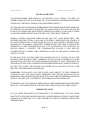


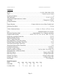


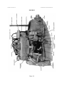

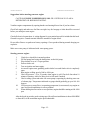

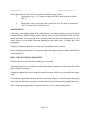


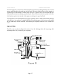
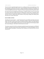
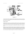

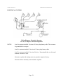
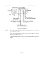
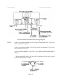
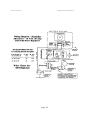
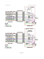
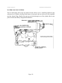


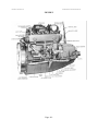
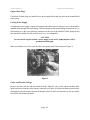
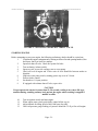
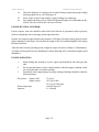
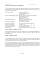

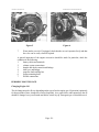
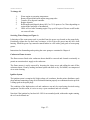


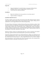
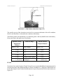
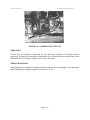

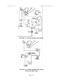
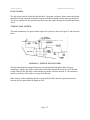
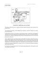


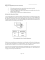
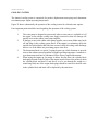
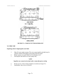
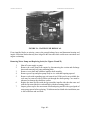
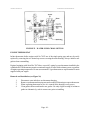
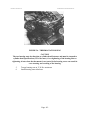
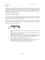
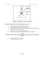
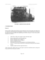
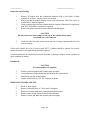
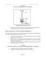


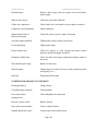

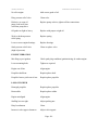


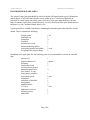


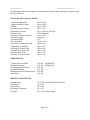
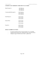


![RS8CH422 AK2 IO [w-AKC 55] User Manual](http://vs1.manualzilla.com/store/data/005784090_1-938eac098068c47f936e9b0d54a0884d-150x150.png)