1
KB-111A
Speaker Station
INSTRUCTION
and
SERVICE MANUAL
1i zIbl11
Clear Corm
intercom Systems
945 Camelia St. Berkeley, California 94710 510-527-6666
Clear-Com 810026
8/15/88 REV. C
**
**
*k* * t*
**
DOCUMENTATION ADDENDUM
KB-lilA MANUAL
REV.A
November 17, 1987
t*t* * ****s:
C**:*t*X***** *. : k * i
***X*i**
**
**
A.kAt
:i
X.A.A
t A*I:i *1
tA At
XttA
MIC TO LINE GAIN LEVEL INCREASE
In effecting a 4d4 Mic to Line increase in gain level,
following changes have been made:
Chanqe:
At:
270K OHM
R18,
27pf
C9
180pf
To:
36
390K OHM
iSpf
0
!Onpf
the
CLEAR-Con KB-i11A SPEAKER STATION
INSTRUCTION & SERVICE MANUAL
TABLE OF CONTENTS
Section
I
II
III
IV
V
VI
0
Page #
Introduction to the KB-lilA .................. 1
Headsets and Mics ............................ I
Installation ................................. 3
Operating Controls ........................... 7
Parts Listing ................................ 8
Specifications ............................... 8
VII Call Signalling Modification ................. 9
Illustrations
Figure
Figure
Figure
Figure
Figure
Figure
Figure
Figure
.
no ricr:
1:
2:
3:
4:
5:
6:
7:
8:
Headset Y-Cable ........................ 2
Headset Extension Cord ................. 2
KB-llA Mounting Dimensions ............ 4
KB-l1lA Block Diagram .................. 4
Two-Channel Interconnect Wiring ........ 5
Portable Unit Connections .............. 6
Alternative Signalling ................. 9
KB-lilA Schematic ..................... 10
-
While Clear-Com makes every attempt to maintain the accuracy of the
information contained in its product manuals, the information Is subject to
change without notice:7
I.
INTRODUCTION TO THE KB-llA REMOTE STATION
The Clear-Com KB-llA is a Remote
Speaker Station that provides talk/
listen communications on one of two
channels within our closed-circuit
intercom system.
It features a
wide frequency response, high output speaker and the ability to
operate with a carbon headset OR a
dynamic headset, handset, or pushto-talk mic.
The KB-llA provides an adjustable
sidetone circuit which allows you
to vary the level of your voice as
you hear it in your
headset or
speaker. The circuit also prevents
feedback when using the speaker and
a mic simultaneously.
You need
only adjust the sidetone once, even
if other Stations subsequently join
or leave the intercom system.
The KB-ll1A features the Clear-Com
contoured frequency response for
consistently excellent speech intelligibility in all surroundings.
The speaker delivers crisp sound
pressure levels, clearly audible in
high- or
low-noise environmentsThe Remote Station features Automatic Headset Detection; its built-in
mic preamp automatically shuts off
when the headset is disconnected,
eliminating noise pick-up on the
intercom line.
The intercom circuitry incorporates a mic limiter,
which assures constant talk levels
and prevents overload.
Designed for custom-mounting, the
KB-llA is built on a charcoalbrown, aluminum panel, 5/32" thick,
that can be installed in a cut-out
in any convenient surface, or mounted inside a 6" x 8" Nema electrical enclosure. The Station connects
to the intercom system via a 5pin terminal block behind the front
panel.
The KB-lilA's speaker can remain on
at all times, or you can turn it
off so that private conversations
may be carried out with a headset
or telephone handset. The threeposition mic switch allows you to:
1) keep the mic on at all times;
2) activate the mic momentarily;
3) switch off the mic so the KBllA can function as a "listenonly" station.
II.
Clear-Com offers the "P" Box, which
allows you to convert the KB-lilA
to a portable Remote Station. The
P-Box is a sturdy, sloped-front,
steel enclosure with solid walnut
sides.
When installed in a P-Box,
the KB-lilA connects to the intercom system with 3-pin, XLR connectors.
When the KB-lilA is installed in
the P-Box, it provides talk/listen
capability on one channel.
Standard two-conductor shielded mic
cable interconnects stations within
the intercom system.
HEADSETS AND MICS
To provide you with the ability to
talk on the intercom channel, the
KB-lilA contains:
--one 1/4" phone jack for a standard carbon headset, AND
--one 4-pin, male, XLR-type connector (D4M) for a dynamic headset,
telephone-style handset, or pushto-talk mic
The
KB-lilA's built-in headset/
speaker amplifier can drive a standard headset to levels greater than
110 dB SPL.
The Station's mic
preamp automatically shuts off when
the headset is disconnected, thereby eliminating hum pick-up.
NOTE: If you use a carbon headset
and a dynamic headset simultaneous-
ambient
isolation from
greater
noise- Clear-Com also offers Model
a telephone-style handset
HS-6,
with a dynamic mic and push-to-talk
switch; it is interchangeable with
the above headsets. All units have
field-replaceable cords.
ly. the listen-level in the carbon
headset drops audiblyThe carbon headset connections are:
Headphone
Ring-Mic
Tip-Sleeve-- Ground
dynamic
The KB-111A drives two
headsets with only a slight (3 dB)
reduction in level. Clear-Com can
supply you with Model YC-100 "Y"
Cable, which allows you to plug two
headsets into the one D4M connector
on the Station's front panel.
The D4M connector pins are:
Mic Ground
Pin 1:
Mic Hot
2:
Pin
Headphone Ground
Pin 3:
Headphone Hot
Pin 4:
To assure proper level and performance, the dynamic headset should
have the following characteristics:
dynamic
Microphone type:
150-250 ohms
Impedance:
-55 dB
Output level:
dynamic
Headphone type:
300-2000 ohms
Output impedance:
Alternately, you may construct your
own Y-cable; we recommend you use
Belden 8416 or the equivalent (2conductor, 25 gauge) or Belden 8734
or the eqivalent (3-conductor, 22
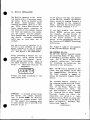
gauge). See Figure 1.
You can also build an extension
cord for a dynamic headset, using
Limit
the cable specified above.
its length to 15 feet or less;
greater lengths lead to possible
capacity coupling between the mic
and the headset signal,
signal
which causes oscillation or a loss
in frequency response. See Fig. 2.
dynamic
offers three
Clear-Com
headsets, all with boom-mounted,
noise-cancelling mics. Model CC240B is a double-muff and Model CC75B is single-muff; both have boomactivated mics with on/off switches. Model PH-7 is a very rugged,
double-muff, high-fidelity headset
with wider frequency response and
FIGURE 1: HEADSET
-
a
CABLE CONNECTIONS
A4m
CAU~fJON:DO NOT CONNECT
MIC GROUND HEADPHONE
0eUN0 TOGETHER AT
POINT
~~~~~~~~~~~~~~~~~~~~~~ANY
A4F
A4M
PIN: MIDNOTO
PIN)3:.E~lHOE WO"OND
Pn 4: MEAVHONE NOT
FIGURE 2: HEADSET EXTENSION CORD
IS
LESS
PIN'I:SICOROUN
DONOTCONNECT
CAUTION:
WOUND
PIN3:HEADHONE
TOGETHER
GROUND
PIN 21MIC POT
PIns:;HAMOPOE NOT
2
OR
EIC GROUND
I
HEADPHONE
.
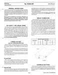
II. KB-l1lA INSTALLATION
The KB-lilA connects to the intercom system with a five-screw terminal strip, which is located on the
PC Board.
Route two-pair
(individually shielded) cable (i.e. Belden 8723) from a Main Station or
Power Supply output connector to
the location of your Remote Station
(or route two separate, two-conductor mic cables, one per channel).
Each channel must be fed within its
own shield,
although unshielded
cable may be used when run in
conduit.
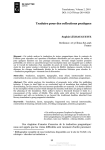
The KB-llA can be mounted in a
cut-out in any surface, or it can
mount inside a 6" by 8" Black
(electrical) Box (minimum depth,
3").
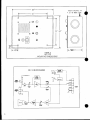
See figure 3 for dimensions.
After preparing a surface for installation, bring wiring into the
header
on the terminal
strip.
While making connections, refer to
the lable adjacent to the terminal
strip; it identifies each pin by
assignment:
Fr--CH.
I CH.
30When
1 30vA 1+
A_ _ 1
Connect the leads according to
label shown above.
.
the
IMPORTANT
to prevent ground loops
and buzzes, the common terminal
(pin 5) should NEVER be directly
connected to chassis ground
(pin
1).
Use conduit or a separate wire
to interconnect two or more KB-lilA
Stations to pin 1.
If you plan to use only one channel
on the KB-llA, disable the Channel
Select switch by jumping Channels A
and B together on the connector
block, and hook the intercom audio
line to either terminal 2 or 3.
If you don't disable the Channel
Select switch and are only using
one channel, you must be sure to
keep the Channel Select switch set
to the active channel.
If you
switch to the unconnected channel,
the Station will exhibit disturbing
oscillation.
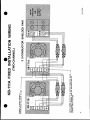
See Figure 5 (page 5) for examples
of KB-llA Two-Channel Wiring.
THE PORTABLE KB-llA
The KB-lilA may be mounted inside
the Clear-Com Model "P" Box, thereby becoming a portable Remote Station. The "P" Box is supplied with
a handle, rubber feet, and screws
for attaching the handle and the
intercom to the enclosure.
the KB-11IA is mounted in the
P-Box, only one channel can be used
for communication.
The wiring in
the P-Box contains a jumper to
defeat the Station's Channel Select
switch.
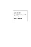
The portable Station connects to
the intercom system with the 3-pin,
XLR
connectors located on
the
side of the P-Box. There is one
female connector for input,
and
one male connector for extending
the intercom line to other Remote
Stations. Inside the P-Box, the
connectors are wired to a 5-pin
terminal strip, which you plug onto
the header on the KB-li1A PC Board.
Refer to Figure 6, Portable Unit
Connections (page 6).
--continued--
3
8.6
KB-lilA
A 6"x 8' BACK
5.4
.5 5
6.5
BOX
E
_
_
__
_
H1.25"MIUH
_
3"
FIGURE 3
KB- Il/A
MOUNTING DIMENSIONS
KB-111A BLOCK DIAGRAM
5
4
IN
MOUNTS
__
_
_
, 3
¢
>~~
Luo,
~~~~l
ggti
I i;
.
.;';
0
'
_
z~~~~-.
§
l~~~~~~~~~M
ixi- 0
>
li;£0,0f;.;1S,,
:
~
1
To install the KB-ll1A in a P-Box:
1) Remove the plastic screw terminal block from the header on the
KB-111A PC Board; pull straight
up to lift block off.
on each side for hanging it from
the wall,
a console, or where
ever.
Use standard two-conductor mic cable (i.e., Belden 8413) with 3-pin
connectors to interconnect the portable station within the intercom
system. The pin-out assignment for
each XLR connector is:
2) A
similar terminal block is
wired to the P-Box's 3-pin connectors; plug that block onto
the KB-lilA's 5-pin header.
The
terminal block and the PC Board
are clearly labelled with the
pin numbers to ensure proper
connections. See Figure 5, Portable Unit Connection.
Pin 1-- common
Pin 2-- +30 volts DC
Pin 3-- intercom audio
3) Because the P-Box accepts one
channel, the KB-lilA's "Channel
Select" toggle switch is ineffective. No matter which position this switch is in, the KBll1A operator communicates
on
the one channel that's fed into
the P-Box-
Route cable from the Main Station,
Power Supply, or another Remote
Station to the portable KB-lilA,
and input to the female connectorUse the male output connector to
"daisy-chain"
the intercom line
between the KB-llA and another
portable Remote Station.
4) Attach the KB-llA to the front
of the P-Box, using the supplied
screwsIf desired, attach the
handle and the protective rubber
feet onto the suitable sides.
The enclosure also has cut-outs
A diode in the DC input of the KBlilA protects the circuitry against
wiring in the interconnect cables.
All
Remote Stations bridge the
terminated audio line with approximately 15k ohms.
FIgure 6: Portable Box Connections
INTERCOM
\
0
Remove original
\
PC
termhinalblock
/
-~BOARD
/
e/haleT1.r
/
'aPP-Box:.peel
ofl
Antet
,
~
e
Fteingn
P
pee (M)
6
apphopriate. d
-
O
IV. KB-l1lA OPERATING CONTROLS
"A/B Chan. Select"
This
toggle switch selects the
channel on which the operator will
communicate.
(This switch is defeated when the KB-llA is mounted
in a P-Box.)
"Volume"
This knob adjusts the listen-level
for the speaker/headset.
"Speaker On/Off"
This toggle switch determines
activity of the speaker-
the
1)
2)
3)
4)
plug in headset
turn on mic
turn up volume all the way
insert screwdriver into hole and
engage the slot on the trimpot
inside
5) begin talking into mic while
slowly turning screwdriver; the
volume of your voice will rise
or drop.
When using both the
headset and the speaker, set the
sidetone for maximum null (you
can't hear yourself).
"Mic On/Of f/ (On)"
This three-position toggle switch
determines
the activity of the
microphone in your headset, handset, or gooseneck. When the switch
"Call"
The black push-button activates the
visual signal circuit that's stan-
is set
dard
to the top "on"
position,
the mic remains on.
When it's in
the middle position, the mic is
offThe bottom "(on)" position is
a momentary setting.
"Sidetone Adj."
The sidetone control enables
the
KB-llA
operator to adjust the
level of his/her voice as heard in
the Station's speaker or headset,
allowing up to 35 dB reduction of
acoustical pick-upYou need only
adjust the sidetone once
(if at
all), even if other stations subsequently join or leave the intercom
system.
Adjusting the sidetone
does not affect the level of incoming or outgoing signals.
.
sidetone to be approximately 6 dB
lower than incoming signals.
If
you want to change this level, take
these steps:
The sidetone control is inside a
hole next to the Volume knob.
Use
a small blade screwdriver for adjustment.
At the factory.
Clear-Com sets the
on Clear-Com
intercoms.
It
allows the intercom user to attract
the attention of operators who have
removed
their headsets or turned
off their speakers. Call signalling
follows the position of the Channel
Select switch; for instance, if you
are using Channel A, pressing the
Call button activates
the signal
circuitry at all stations that are
assigned to Channel A.
As long as
you keep the button pressed, the
Call circuit will stay active.
The Call button also activates the
speaker and/or mic at any other
Station (on the same channel) that
is set up for remote control.
The amber Call Lamp illuminates
when any Station, on the same channel, activates a Call signal.
If you need to receive a Call signal from the channel you're not
using, refer to the special modifi-
cation diagram on page 9.
7
V.
KB-lIlA FRONT PANEL PARTS LISTING
Part #
Description
Oty.
Schematic Reference
210013
210050
240015
240020
Connector, D4M
Connector, 1/4" phone jack
Knob, 1/2" with 1/8" shaft
Button cover, red
(510028- switch, snap-action)
Panel, front, KB-llA
Nut, dress cone
Nut, 1/4" dress
Lamp cover, amber
(390001- bulb, #387)
Speaker; 3" round
Switch, mini toggle
Switch, mini toggle
Switch, 3-position
1
1
1
1
J2
31
P3
Si
1]
2
2
I
Call, Channel Select
Speaker and Mic On/Off
Ii
I
1
1
I
SPi
Speaker On/Off
Channel Select
Mic On/Off/On
250144
280067
280071
390000
500089
510006
510040
510044
VI. KB-111A SPECIFICATIONS
AMPLIFIER DESIGN
Solid-state, integrated circuit amplifiers which include a mic preamp, headset/
speaker power amp, and signalling circuitry.
Current-limited with short circuit
and reverse polarity protection.
MIC PREAMPLIFIER
Freq. Response:
250-12k Hz, with
mic limiter; contoured
to enhance intelligibility
Mic Input:
200 ohms
Mic Preamp Gain:
31 dB
Max Input Before Clipping:
Mic Limiter Threshold:
-20 dB
-37 dBm
HEADSET/SPEAKER AMPLIFIER
Freq. Response:
100-18k Hz, t 2 dB
Load Impedance Range:
8-2000 ohms
(dynamic headset)
Output Level:
+20 dBm, 26v p-p
@ 100 ohms
Headset Level:
>110 dB SPL
with standard Clear-Com headset
Speaker Level:
>98 dB SPL @ 3 feet
Speaker Type:
3" round, 16 ohms
Power Output:
4 watts peak
Distortion:
0.5% THD @ 1kHz
Headphone Amp Gain:
40 dB
GENERAL SPECIFICATIONS
Line Level:
-20 dB avg., 0 dB max.
Sidetone Adj.: 35dB null to full on
Signal Voltage: 11VDC on audio line
Call Light Sensitivity:
4 volts
Signal-to-Noise:
75 dB
Equivalent Input Noise:
-118 dB
Station Bridging Impedance:
>12k ohms (200-10k Hz)
Voltage Range:
12-32 volts,
28v nominal
Power Required:
25 ma quiescent,
60 ma talk, 60 ma signalling,
200 ma short circuit
Dimensions (front panel):
8.6" x 6.5" x 3.25" deep
CONNECTORS
Dynamic Headset:
Male D4M
Carbon Headset:
1/4" phone jack
Line:
5-screw terminal block
(portable unit: 1 Male D3M,
1 Female DU3F)
.
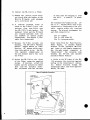
VII. Special Modification: Signalling Configuration in Multi-Channel Systems
In normal circumstances, the KBlllA Call Light illuminates when
someone signals on the channel that
the KB-11lA operator has selected
for communication. This is because
the visual signal travels, in the
form of DC voltage, on that channel's line.
(i.e., KB-lilA) have selected Channel B for communication.
Yet they
want to be capable of receiving a
Call signal from stations that are
communicating on Channel A.
This is achieved by putting four
diodes (914 type) in series between
the two channels on the interconnect cable. Call signalling is now
possible from Channel A to Channel
B. Since the Call signal follows
the direction of the diodes, this
is one-way signalling; Channel B
cannot send a signal to Channel A.
You can alter this configuration by
making the modification described
below.
In our application (Figure 7),
a
group
of
two-channel
stations
FIGURE 7:
iRemote
| Station
TWO-CHANNEL
MAIN STATION
Ch.A
POWER SUPPLY
Ch i.BAm
|
ALTERNATIVE SIGNALLING
|Remote
| Station
|
.
1
1
t
>
/ BllR8
A BOAB1A
DIODES (4)
914 Type2
Sao
h
tto
2 h2-.
tto
9
Figure 8: KB-i1 1A SCHEMATIC
*1
II
i
0-
i
+
~~~~~~~~~~~~~q
mE
n~~~~~~~~~~~~~~~~
l
,
1AWNtHD
I2
{'
1
X
11
rn4
UN
*
Stt 9eoO
L
U
L
10~~~~~~~~~~~~
8g
11
onC~Un
'4
>~~~~~'
J~~~~~~~~~~~Uo