1
Erecting
lnstructions
No.76BOILER
Weil-McLain
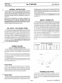
lished dimensions or where excessive resistance to the flow of
combustion gases can be expected, it may be necessary to convert the installation to forced draft by purchasing and install'
ing an induced draft fan.
The chimney must be at least the diameter indicated on the
last page of these instructions under RATINGS to vent with
natural draft.
GENERAL INSTRUCTIONS
Ifthe boiler was ordered as a complete package, thoroughly
check the boiler for any concealed damage. If the boiler was
ordered as factory assembled or freld assembled, open all boxes
and check the contents against the packing lists. In the event
of shortage or damage, notify the transportation company immediately.
Boiler must be installed in accordance with these inBoiler must
structions
so as not to void our warranty.
also be installed in accordance with Section IV of the
ASME Boiler and Pressure Vessel Code and any applicable governmental and insurance codes.
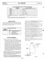
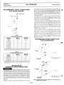
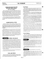
BOILER FOUNDATION
A boiler foundation is recommended where the boiler room
floor is not level or where the boiler room floor cannot support
the weight ofthe boiler. Locate the boiler foundation to provide proper clearances for installation ofthe piping, burner,
and internal water heater(s). Allow a minimum clearance of
22" from the back of the boiler for breeching erection. Allow
18" clearance to the left side for cleaning and for tankless
heaters. Ailow 26 " clearance to the left side if storage heaters
are used. A level concrete pad or curb foundation is suggested
of the size shown in the table and FIGURE 1. The height of the
boiler foundation should be at least 2".
Ifthe boiler is to be installed directly over electrical wiring
or telephone cables in conduit buried in the concrete floor of
the boiler room. a 1" thick insulated mat covered with foil
should be laid on the floor underneath the boiler sections.foil
face uo.
A I R SU P P L Y F OR B OIL E R R OOM
Provisions must be made to supply sufficient air to the boiler
room at all times for combustion, ventilation, operation of the
barometric draft regulator (where used), and prevention of
less-than-atmospheric air pressure in the boiler room. An
opening to the outside with a free cross sectional area of at
Ieast 1 square inch per 7,000 BTUH burner firing rate is recommended (CSA requires 1 sq. in. per 5000 BTUH input). For
each 1,000 feet above sea level, increase the fresh air opening
by 4 per cent. The boiler room should be isolated from any area
served by exhaust fans. DO NOT INSTALL AN EXHAUST
FAN INTHE BOILER ROOM.
B O I L E RF O U N D A T I O S
NI Z E S
B O I L E RN O .
L
B O I L E RN O .
L
C HIMN E YOR V E N T
476
(also reler ro BREECHING ERECTION)
576
30"
876
48"
o/o
JO
976
54"
The No. 76 Boiler is designed for pressurized forced draft firing. The No. 76 Boiler for light oil application can also be fired
with negative pressure in the firebox for natural chimney
draft.
The boiler with pressurized firebox for forced draft firing can
be used with a conventional chimney or stub vent. The boilers
with negative pressure in the firebox can only be used with a
natural draft chimney.
On multiple boiler installations using one chimney, consult
Weil-Mclain Application Engineering Department for additional venti ng informat ion.
776
FRONT
l.-......->
,.:' ,.; ,/
',/.:
,:/
,"'
I
,// ,,' /*
.../ l ,/
...11
, 2.---.r
MIN
ForcedDraft
I
When excess negative draft conditions can be expected to
prevail in the breeching or when the chimney or stub vent
height exceeds the published natural draft chimney height,
install the barometric draft control, furnished with the boiler,
in the breeching as close to the chimney as possible.
F I G U R E1
ASSEM BLEDSECTION S
If the boiler was ordered completely packaged or with the
sections factory assembled, locate the unit on the boiler foundation or on the boiler room floor. After the boiler has been positioned, proceed to "HYDROSTATIC PRESSURE TEST OF
BOILER."
NaturalDraft
Be sure the chimney is no smaller than the published height
and cross sectional area. Where the cross sectional area or the
height of the natural draft chimney is smaller than the pub-
P a g e1
WP
Part No. 550-110-185/0383
Erecting
lnstructions
No.76 BOILER
Weil-McLain
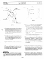
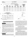
TABLEWITH INDIRECTWATERHEATERS
SECTIONARRANGEMENT
BOILERNO.
M A X I M U MN O .
OF HEATERS
476W& S
576W& S
1
F-Tt-t-B
676W& S
F-Tt-t-Tt-B
F-Tr-r-Tl-l-B
776W & S
F-Tt-t-.-t-Tl-B
876W& S
976W& S
a
Y/
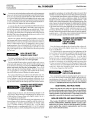
SECTIONASSEMBLY
ALL HEATERSMUSTBE ON LEFTSIDEOF BOILER
F-Tt-t-Tt-t-t-Tt-B
4
F - T t - t - T l - l - .- l - T l - B
Sectionwith TanklessHeater
Section,Tl = Intermediate
F = FrontSection;B = BackSection,| = Intermediate
Opening.
section,but installermustcut jacketside
"A Tl sectioncan be locatedin thispositioninsteadof regularintermediate
panelto accommodale
healeropening-no knockoutis provided.
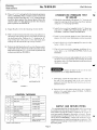
grooves so that a gas-tight seal will be maintained between the sections.DO NOT APPLY adhesir-eto the opposing sealing grooves ofthe next boiler section.
S E A L IN G R OP E
Listed in the SEALING ROPE USAGE TABLE are the
places sealing rope must be used and the diameter and length
ofeach piece. For expediency, the seaiing rope can be pre-cut
prior to starting the section assembly.
4 . Wipe the port openings with a clean rag to remove any
grit from the machined surfaces. Do not use an)'cleaner
that contains a petroleum base distillate loilr to clean
ports. Place Lhe71lz" and 31/2"elastomer sealing rings in
the appropriate port openings (see FIGURE 2 t
SEALINGROPEUSAGETABLE
NOMINAL
DIAMETEROF
CUT
SEALINGROPE LENGTHS ROPEUSAGEAND LOCATION
98"
Perimeterof each Seclion
't2
42"
DrafthoodCollar
58"
BurnerMountinqPlate
3la"
12"
ObservationPort Frame
5 . Combustion products and unburned oil vapor-. can cause
failure of the elastomer sealing rings. After the elastomer
sealing rings have been set in the port openings ofthe sec'
tion, make a r/a" diameter continuous bead of siircone
sealant around the outside ofthe rings. Follou' thrs procedure for each sealing ring installed (see FIGURE 3'.
b.
SECTIONASSEMBLY
Prepare the port openings in an intermediate sectron.The
"TI" intermediate sections (if used) must be tnstalled in
the order given in the SECTION ARRANGEIlENT
WITH INDIRECT WATER HEATERS table Note that
18" clearance must be provided on the left side for cleaning and heater installation.
Discard the i]/g" diameter rods which are requrred only
during shipment. These rods must not be used to draw the
sections together.
1. Prepare the back section for erecting the boiler.
a. Lay back section on floor with ports facing up. Apply
water-glass, as an adhesive, to the target wall area
(i.e., back end offirebox) ofthe section. Press flexible
refractory blanket into position (see Figure 6).
C L E A NO U T
OPENING
b. Locate the back section on the boiler foundation shown
in FIGURE 1. Screw a piece of 3 " diameter pipe at least
22 " long into the 3 " return tapping in the back section.
Block under the 3" pipe to hold the back section upright without additional support. These sections are
top-heavy and will not stand individually without support. Make sure that the section remains plumb. The
3 " di ameter piece of pipe can be removed after several
sections have been erected.
:t
7 1 l z "F L E X 1 B L E
ELASTOMES
RE A L I N G
RING
SEALING
ROPE
2 . Sealing
rope adhesive is in a caulking tube and must be
used with a caulking gun. Make a l/a" continuous bead of
adhesive in the bottom of the curved sealing grooves 1ocated around the perimeter ofthe section.
tt.
-
o
,ti\
lo
Y
31/2"FLEXIBLE
ELASTOMERSEALING
RING
Position the 1lz" by 98" long sealing rope on the section by
starting at the cleanout opening (see FIGURE 2). Be sure
the sealing rope is well seated at all points in the sealing
F I G U R E2
Page 2
Erecting
lnstructions
Weil-McLain
No.76BOILER
,
src_LtoN
l{
1 / e "B E A D
S I L I C O N ES E A L A N T
ff
\1
l jY
l!,-tr
I :--{\l
li
l,
PORT
SECTION
aLIGNMENT
LUG
r
ll
i !
- l t-
rll
socKEr
l
arl al
ELA.T.MER
I i ,i
S E A L T NRGr N G
iil'
rI
I
rlr
ll"
\..,
ELASTOMER
S E A L I N GR I N G
l
1
...:
F I G U R E4
TUBE
S I L I C O NSEE A L A N T
Four : :
F I G U R E3
v
x .1I.r" studs nle provided to secure the burner
n ) o u n t l n g plate to the front section (seeFIGURE 6).
a. Thread tn'o I z " nuts on the rounded end of a 1lz" x41lt"
stud. locking them together, and thread the flat end of
the stud into one of the four tapped holes located
around the burner mounting plate opening in the front
section.
Position the intermediate section so that the aligning
lugs will fit into the sockets of the section (seeFIGURE
4). Oil the threads of four (4) of the draw rods (5/a" x 9 " )
and slip them through the lugs on the top and sides of
each section. Place a washer (only one washer per draw
rod) under each nut to be tightened. Put a drop of oil
between washer and nut.
b. Remove the nuts from the stud.
c. Repeat steps "a" and "b" for the remaining three
studs.
Starting with the draw rods nearest the port openi trgs.
draw the sections together uniformly until the metal
around the ports touch and the pads at the oppositecor'ners touch. When properly pulled together the gap
around the port openings should be less than 0.0112".
Check with a feeler gauge.
Do not continue to draw sections together after metal
to metal contact has occurred. Do not "back off'the
draw rod nuts.
B . Set the remaining boiler sections into position with the
d. For BL-76 boilers, hang one refractory retainer (stainless steel plate) over each mounting stud.
1 0 Make a small continuous bead of sealing rope adhesive in
the groove around the burner mounting plate opening in
the front section. Position the 1lz" diameter by 58" long
rope in the groove making sure the ends overlap at least
1" and install the burner mounting plate using the 1lz"
washers and nuts provided. Make sure burner plate is installed with the round secondary air opening to the left
(see FIGURE 6).
1 1 . Make a small continuous bead of sealing rope adhesive in
"TI" sections placed (ifused) in the proper ordel given in
the SECTION ARRANGEMENT table. Check the sealing
rope seal ofeach section before proceeding to the next section. The boiler must be sealed gas-tight.
the bottom ofthe sealing groove located around the flange
ofthe front observation port assembly. Position the 3/s"
diameter by 12" long sealing rope in the sealing groove
making sure the ends overlap at least 1 ". Install the front
observation port assembly using the number 10-32 x 3la"
truss head screws provided (see FIGURE 6).
72. If the boiler was ordered with "TI"
intermediate section(s), install the indirect water heater(s) and gasket(s) or
heater opening cover plate(s) and gasket(s) using the 3/a" x
3/+" hex head screws and washers provided (see FIGURE
6).
Use of chemical cieaners or sealants
in any Weil-Mcl,ain boiler is not recommended.IN PARTICULAR, PRODUCTS CONITAINING PETROLEUM DISTILLATES MUST NEVERBE USED INTYPE 76 BOILERS!
Page3
Erecting
Instructions
No.76BOILER
13. Place a rl+" x lrlz" carriagebolt in the cleanout opening as
shown in FIGURE 6. Place a washer and nut over the bolt
to hold it in place. Place the L}rlz" x 1?s" cerafelt blanket
insulation pieces against the cleanout plates. Mount the
cleanout plate over the opening and bolt the cleanout
plate in position (see FIGURE 6).
HYDROSTATICPRESSURETEST
OF BOILER
v
1. If the boiler was ordered with optional 11/2" cleanout and
inspection openings on the sections, plug these tappings
using the 1r/z" brass plugs provided.
Install a drain cock (not supplied) in the 3/+" drain tapping (size to ASME Code requirements). Refer to the
CONTROL TAPPING TABLE and FIGURE 5.
14. Repeat Step No. 13 for the remaining cleanout plates.
t<
Weil-McLain
Make a small continuous bead of sealing rope adhesive in
the bottom ofthe sealing groove around the perimeter of
the draft hood collar. Position the:tls" diameter by 42"
long sealing rope in the groove on the draft hood collar
making sure the ends ofthe rope overlap at least 1".
J.
A
Install a water pressure gauge in one of the boiler tappings so the boiler water test pressure can be measured.
Install a bleed valve in boiler tapping K to vent air as the
boiler is filled rvith w'ater.
1 6 . Position the draft hood collar to fit over the flueway outlet
on the back section. Secure the draft hood collar to the
back section using the 3/e" x 1" hex head cap screws and
washers provided (see FIGURE 6).
Plug all remaining boiler tappings, including the returns. Refer to the CONTROL TAPPING TABLE and
FIGURE 5.
Fill the boiler with water and completely vent all air. Test
the boiler with water pressure not exceeding 45 pounds
per square inch or 1rlz times the boiler working pressure,
whichever is greater.
E,
Submit the boiler to this test lor at least
10 minutes but for no longer than 30 minutes.
] NPT
RFT!tsN
I
r r i ?I
i4
7. Thoroughly inspect the entire boiler fcrr$ater leaks. At
the end of the test period, look at the $'atrr plessure
gauge and ascertain that the water test pressure has remained constant.
I
INTERMEDIATE
8. Drain the boiler and remove p l u g s f r o m t h o s e t a p p i n g s
which will be used. Refer to t h e C O N T R O L T A P P I N G
TABLE and FIGURE 5.
C O N T R OLT A P P IN GS
L0cal0n
Size
Steam
A
ltlz"
Safety
Valveand/orSkimTapprn0
B
1112" SafetyValve
c1
Water
HighLimitControl
Relief
Valve
Safety
Comblnation
HighLimitand
LowLimitControl
c ]& c 2
WaterLevelControls
Low-Water
Cutoff
Dr & D2.
WaterLevelControls
Low-Water
Cutolf
c 0c
LlqL2
112
F1&F2
S U P P L YA N D R E T U R NP I P I N G
It is recommended that the system supply and return piping
be installed and the piping connections be attached to the
boiler before erecting the jacket or installing the contt'ols to
avoid any possible damage to the jacket or controls. Recommended piping arrangements for No. 76 water and steam boilers are shown in FIGURES 7, 8 and 9. The mrninrum recommended pipe sizesare listed for each piping arrangement. The
supply and return piping will not interfere with the erection of
the boiler jacket.
Gauge
Glass
TryCockTappings
G
tlz"
Pressure
LimitControl,
Pressure
0perating
Control
andPressure
Gauge
PressureCombination
Temperature
Gauge
n
3ld'
Drain
Drain
K
3ln"
Piping
ToCompression
Tanko
Automatic
AirVent
Available
onspecial
request
only
Page4
Erecting
Instructions
No.76 BOILER
a,I
Qo @
)
\."
\.\
'---l
t\
,l7zl
Ir,. i
l
!.-
-!-
,J
.t
.
Weil-McLain
{
I z
a
& t ) ' , ' 1 1l l ,,
;f/<'/-
,','
--,.1
i*r/1rt.
l r )i ,'n
tvr
'u
,/
iD
\
\.\
-\
I
lY
I
I
l' 'l'(
6\
(j/
- \A
,P, {
o
@
/.\
v - Qh\,e'
\-*r"
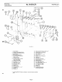
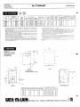
F I G U R E6
1.
2.
3.
4.
5.
6.
19. Observation
PortScrew10-32x31t"
20. ObservationPortAssembly
21 SealingRope,s/e"
22. Stud,Tap End,1lz"x41lc"
23. Hex Nut, 1/2"
24. Retainer,Front Refractory
25. Washer,1/2"
26. Wing Nut, 1/a"
27. SecondaryAir Shutter
28. MachineScrew1/a"x 11/2"
29. SealingRopetlz"
'30. Front PlateRefractory
31. ClearSighlGlass2" Dia.x 1la"
32. 7112"
SquareCut Seal
33. 3112"
SouareCut Seal
34. Washers/e"
35. Hex Nut 5/s"
36. InsulatedCombustion
ChamberBackPiece
FrontSection
Section
RegularIntermediate
Section
TanklessIntermediate
Back Section
BurnerMountingPlate
CerafeltBlanketInsulation
1O1lz" x 17|e"
7 TanklessHeater
n TanklessHealeror Heater
Cover PlateGasket
9. HeaterCover Plate
10. CaPScrew,s/a"x sk"
1 1 . D r a wR o d ,s / s "x 9 "
12. D'atl HoodCollar
13. CaPScrew,sie"x 1"
'14. Washer,3/s"
15. CleanoutPlate
'16. CarriageBolt,1/+"x 13/a"
17. Washer,1/4"
1 8 . H e x N u t ,1 / a "
' For BG and BGL-76boilers,refractoryis cast into burner mounting
olate.
J
P a g e5
Erecting
lnstructions
No.76 BOILER
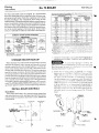
R E C O M M E N D EPDI P I N GC O N N E C T I O N S
FOR WATERBOILERS
TO
SYSTEM(FRoNr oHry)
CCI',4R
PESS ION
TANK -
(
a/-
I
I
I
\:,'
ll
tl
tl
tl
t t(D".1
F I G U R E7
TABLE I
FORKNOWNFLOWRATES'
WATER
FLOWRATE
GPM
To9 GPM
1 0 - 1 6G P M
SUPPLY
PIPESIZE
A
RETURN
PIPESIZE
B
11la"
1112"
11 l z "
36-50 GPM
2112"
2112"
5 1 - 7 6G P M
J
17-21 GPM
mended piping connections and minimum recommended pipe
sizes for No. 76 water boilers. Reverse water flow through
the No. 76 water boiler is not recommended. In most cases
it is advisable to pump water away from the boiler by connecting the supply piping to the inlet side ofthe circulator, as illustrated in FIGURE 7.
The supply and return piping and the compression tank are
not supplied r.r'ith the boiler but should be installed as illustrated. Controls are not shown in FIGURE 7 in order to more
clearly show the water boiler piping.
In sizing the supply and return piping, start with the minimum recommended pipe size and proceed at full diameter for
10 times that diameter before making any reduction. For example a 3" return should not be reduced any closer to the
boiler return tapping than 30". Horizontal expansion tank
piping must pitch upward at ieast 1" for each 5 feet of piping
from the borler to the tank.
Where s)'stem temperature modulation is achieved by
means of three'x'a1' valves, care must be exercised in piping
the system to protect the boiler from thermal shock which
could result from returning room temperature water at high
velocities to the hot boiler. Where three-way valves are employed, consult Weil-McLain Application Engineering Department for piping recommendations. Primary-secondary
pumping is preferred.
A
f-r
s/s-EM,..;bv,'
,,ra..
,
,,/
lemperature rasethrough boiler rs permissrble when borler prprng conneclrons are sized
using above Table 1 INTEFiMITTENT flow at HIGH velocitres may damage any boiler
676 and 776
\
RETURN
PIPESIZE
B
-t
,(
,,/
j
A
\ ;
4''
sHoRl
tliPi'-.iE
,'-2'
z
2112"
.'
3r;YfltF
TABLE II
FOR UNKNOWNFLOWRATES''
476 and 576
r'
J
'Hagh
BOILER
NUMBER
a
n
22-35 GPM
SUPPLY
PIPESIZE
A
v
PIPINGCONNEC T ION S
RECOM M ENDED
FORSTEAMBOILERS
1
11Ia"
Weil-McLain
//
'
u
J
srEAM BotLERPtPtNG
476AND576
.oHBFUmtr
2112"
F I G U F E8
.
876 and 976
"All pipingsizesare basedupon 20" F temperatureriselhroughthe boiler For use ol other
temperaturerisesthroughthe boiler(i.e.higherflow rates)determinethe flow rate and use
TableI for oioesizes
WATERBOILER
PIPING
SUGGESTED
CONNECTIONS
Improper piping systems and,/or under-
sizedpiping can contribute to erratic boiler operationand possible boiler damage.The piping system must be installed as
illustrated using the recommendedminimum pipe sizes for
the respectiveboiler. Consult your Weil-Mclain distributor,
field salesmanor field sales oflice, or Weil-Mclain Applications Engineering Department before attempting to install
any alternate piping systemsor smaller than recommended
prpe srzes.
FIGURE 7 and the accompanying tables show the recomPage 6
HORT
IPPLE
FIGUFE9
,/
,,/
S T E A | ' \B
4 O I L E R P I PN G
976
6 7 6T H R O U G H
Note: A minimum ol 24" lrcm the water line to the botlom of the
header is recommended.
v
Erecting
lnstructions
Weil-McLain
No.76BOILER
CONDENSATERECEIVERCAPACITY
Y
Gross
Output
Pounds
ol Steam
PerHour
Boiler
Number
476
576R
576
b/o
Minimum Condensate
ReceiverCapacity
Gallons
of
Condensate
Per Hour
1 5M i n .
Boiler
Operation
JZ
10
38
11
336
41
12
408
49
1q
264
323
776
480
876
976
552
624
18
58
67
75
20
23
3 0M i n .
Boiler
Operation
20
22
24
45 Min.
Boile.
Ooeretion
60 Min.
Operation
Boiler
30
33
36
40
'I
44
2
48
60
.4
9
30
36
45
40
46
60
72
80
69
92
54
Recommended
Maximum
Condensate
Feed Pump
Capacity
G . P . M .a t
15PSI
6
2.2
2.5
STEAMBOILERPIPING
PIPESIZES
MINIMUMRECOMMENDED
Riser
Pipe Size
Fig.
No.
v
A
B
Header'
H
Equalizer
J
3"
1112"
b
qto
8
576
v
b/t)
2112"
2112"
4"
1112"
9
Ito
2112"
2112"
11lz
I
876
976
4"
4"
3"
4"
a
I
'24"
BoilerSize
TO
F I XT U R E S
3"
3"
J
,'
1112"
ALTERNATE
F I G U R E1 O
Minimum lrom waterline to h€ader
ings with extended system piping, nuisance shutdowns sometimes result when the condensate returning from the system
lags behind the evaporation capacity of the boiler. To maintain a steady water line, avoid the introduction of excessive
amounts of raw make-up water. To prevent nuisance shutdowns due to a temporary low water level, it is recommended
that a low water cutoffand pump control, condensate receiver,
and condensate boiler feed pump be installed. Refer to the
Condensate Receiver Capacity Table for recommended receiver sizes and condensate feed pump capacity.
S T EA MBO IL E RP IP IN GA N D H E A DERS
P IP IN GC ON N E C TIONS
SUGGESTED
Improper piping systemsand/or under
sized piping can contribute to erratic boiler operation and possible boiler damage. The piping systems must be installed as
illustrated using the recommended minimum pipe sizes for
the respective boiler. Consult your Weil-Mclain distributor,
field salesman or field sales office, or Weil-Mclain Applications Engineering Department before attempting to install
any alternate piping systems or smaller than recommended
pipe sizes.
ATTACHINGTHE JACKET
The boiler should be pressure tested and the supply and return piping may be attached before the jacket is erected. Make
sure that only the plugs and other accessories listed to this
point in the instructions are mounted on the boiler. Follow the
Jacket Erecting Instructions packed in the jacket carton for
jacket installation procedures.
FIGURES 8 and 9 and the accompanying table show recommended piping connections and minimum recommended pipe
sizes for No. 76 steam boilers. The supply and return steam
piping is not supplied with No. 76 steam boilers but should be
installed as illustrated. Controls (safety valve, low water cutoff, gauge glass, etc.) are not shown on the steam piping diagrams in order to more clearly show the steam piping and
Hartford Loop. A minimum of 24" from the waterline to the
header is recommended.
HEATERHOOK-UP
TANKLESS
Where the boiler was ordered with tankless heater(s) it is
recommended that the piping to and from the heater be sized
no smaller than the heater inlet and outlet piping connections.
The tankless heater piping should be installed as illustrated
in FIGURE 10. Where the boiler was ordered with multiple
tankless heaters, a cold water supply header with individual
risers to each heater must be employed and the hot water out-
J
The satisfactory operation of any steam
heating boiler depends upon adequate return ofcondensate to
the boiler to maintain a steady water level. In rambling build-
Page7
Erecting
lnstructions
R e c o m m e n d e dL o c a t i o n sF o r L o w W a t e r C u t o f l ,W a t e r F e e d e r sa n d P u m p C o n t r o l l e r s
S t e a mB o i l e r s . '
W h e nU s e do n W e i l - M c L a i n
L O C A T T ON O . 2 >
L O C A T I O NN O . 1
C a s t l n gL l n €
Casling LlnO
Prlmr ry
Lmtion Below
First Back.up
Loc!llon Bolow
Water
Walor Llno
Waler
Llne
Waler
Lev€l
D l m .A
Conlrol.
Dtm.A
Control.
lets from each header must be headered. It is recommended
that a flow regulating valve be installed in the cold water supply piping to each heater. Each flow regulating valve should
draw rating of each
be sized according to the intermittent
tankless heater. Do not pipe multiple indirect water heaters in
series. An automatic mixing valve may be installed in the domestic hot water supply piping from the heater{s) to regulate
the domestic hot water temperature. Install the operating control in the control tapping in the heater plate. In hard water
areas, it is advisable to soften the cold water to the heater(s)'
TAITKTESS
HEATERS'
"'Continuous
Draw
GPM
"lntormitlrnt DrawGPM
100.
100oAvamge
Temnerrltrra Risa
Temoeraluro
Rise
4 . 0G P M
4 5 GPI\,|
HTATERS'
STORAGE
35 S-29
Heater
r80"
212"
Gallons
]lsalerCaDaclty
/|(l'-140"Riso
]lcaterCapacltyGallons
{0q140"Bise
205rn 3 Hrs
93&94
150
lnlel and
0utlet Taoolnos
314"
.
t
I
>
\-
2!/i'
i
93&941
93&941
150!
2
150t
2
2
2
41/2"
41/2"
15O1/t
41/z'
6 1& 6 3
41/2"
6 1& 6 3
247-2
41/2"
4Y2
5 1 - 2& 5 1 - S - 2
4fz
247.2
5 1 . 2& 5 1 - S - 2
41/2"
4'/2"
Other man!faclu'e's ::^1/3 s provrdrng similar function may be used provided they
are properly locatec a^a a'e selected to handle the boiler evaporative capacity.
Control locatrons as ": aaiec above reler to the control body mark or line on the con'
trol body casl ng
'--:l a^ c. y pump controller function should only be used on
Use low waler c!lc"
"highest conlro c:al :'-^:' :^ :^ ' 3a.x up controller to provide low water cut-off tuncp
u
m
p
c
o
n
l
r
c
Use
on.
tion,or low wale':-l :" a^:'€ae"!nct
^su'ngagency,consultWeil-McLaintechnicalsel
:.e::'
lflocaiionNo 2,s^.'a
vicedepartmenl'c' a :e'-a'e ::a: a^
2. Install the lorr *'ater cutolT see FI(]LR!l lf in accordance rvith the CO\TRol- TAPPI\GS Table and FIGU R E 5 . W h e r e i t n o p ! t { ) n a ri o s s ' a t e r c u t - o f f .c o m b i n a t i o n
l o w w a t e r c u t - o f f a n d t e e d e r .o r c o m b i n a t i o n l o w w a t e r
cut-off and pump control ts enlplol ed. install the control in
accordanceri ith the C'O\TROL TAPPING table and FIGU R E 5 u s i n g f i t t r n x s n o t i u r n i s h e d r .I f a l o w w a t e r c u t - o f f
is to be used that rs not dimensionally diagrammed in
F I G U R E 1 1 . l o c a t e! h e c a s t - o nb o d y m a r k o f t h e c o n t r o l 2 "
below the normal s ater ltne. Do not use a water level control with quick hook'up fittings on any No. 76 steam
boiler.
PRESSURE
6AUGE\
.\
loN
L OCAT
N O?
\
-.II ,
T
i
\__,\)
tJ'
ht,t*fr&ot
Low
lqEmow
(2 REo.D)
WATER
CUT-OFF
€tr--
2'i.
2
6 1& 6 3
93t & 941
To avord uater damage or scalding. the
Steam Boiler:
A low water cutoff, safety valve, pressure gauge, gauge glass
and cocks, blow down valve, and operating and limit pressure
controls must be installed on this boiler to meet ASME code
requirements.
@Fr_--\*_T
4'L
safety valve outlet must be prped !o a t-loordrain or near to the
floor. Do not pipe the safet.r'r'al"'e dr.char{e to anl arua \\'here
V
freezing temperat ures couI d rxcur.
INSTALLBOILERCONTROLS
,
31/."
1. Install the steam safell' r'alve in the proper tapping as ind i c a t e di n t h e C O \ T R O L T A P P I N G t a b l e a n d F I G U R E 5 .
Where the boiler was ordered with storage heater(s), for best
operation the domestic water storage tank should be located
as high as possible above the storage heater(s). A vertical domestic water storage tank may be used if the bottom of the
storage tank is located above the boiler. To maintain optimum
gravity hot water circulation, the horizontal flow piping from
the storage heater{s) to the tank must pitch upward at least 1
inch for each 10 feet ofpiping and the horizontal return piping
from the storage tank to the heater(s) must pitch downward at
least 1 inch for each 10 feet ofpiping' Use as few pipe fittings
as possible so that the least possible resistance will be encountered. The STORAGE HEATER RATING table gives the storage heater capacities and the recommended storage tank size'
i
31/,"
93&94
150
STORAGEHEATERHOOK.UP
i--;
41/2"
93&94
5 1 . 2& 5 1 . S - 2
217.2
61&63
lnlotand
0utlelTaoDinos
14(lrn ll Hrs
816
250-500
200-500
Rscommendod
1"
Gallons
Gallons
Tanl
Sloraoe
' Werll\.'!cLain
Ratlngs
watertemp
lr0m40o10140"with200'F bOrler
" Gallons
01Waterp;r min healed
perlod
"' C0ntrruous
Draw-norecovery
LOCATION
3
150
6 1 ,6 3
DOMESTICWATERHEATERCAPACITIES
HEalol
W e i l - M c Lai n
No.76 BOILER
-----+
aF I G U R E1 2
F I G U R E1 1
Page8
SYPI{ON
Erecting
lnstructions
v
No.76 BOILER
Weil-McLain
3 . Install the gauge glass cocks, water gauge glass and
gauge glass guards in accordancewith the CONTROL
TAPPING table and FIGURE 5.
4 . Install the steam pressureoperating and high limit controls and the pressure gauge in the proper tapping as indicated in the CONTROL TAPPING table and FIGURE 5.
Use the pigtail syphon and fittings furnished (see FIGURE 12).
5. Install any additional or optional steam boiler controls according to the control manufacturer's instructions.
Two (2) pressure limit controls are furnished as standard
equipment to perform low limit (operating) and high iimit
functions. The pressure limit control used as the operator
should be set according to the design requirements of the system. The pressure limit control employed for the high limit
function should be set at least 2 PSIG higher than the operating control setting, where possible (15 PSIG maximum allor+'able steam boiler pressure).
For additional information on the controls. refer to the
instructions.
control manufacturer's
1. Install the pressure reliefvalve in the proper tapping as
indicated in the CONTROL TAPPINGS table and FIGURE 5.
To avoid water damage or scalding, the
reliefvalve outlet must be piped to a floor drain or near to the
floor. Do not pipe the reliefvalve discharge to any area where
freezing temperatures could occur.
A combination low limit (operating) control and high limit
control is furnished as standard equipment. The low limit (operating) control should be set according to the design requirements of the heating system. The high limit control should always be set at least 20'F higher than the low limit control
setting, where possible (250'F maximum allowable boiler water temperature).
For additional
information
on the controls.
control manufacturerts
instructions.
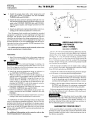
The No. 76 boiler for forced draft firing differs from the No.
76 boiler for natural draft only by the addition of a manually
adjusted flue collar adapter with built-in breeching damper
tsee Figure 13t. Long horizontal breechings, excessive numbers ofelbo*'s or tees, or other obstructions which restrict the
florv of combustion gases should be avoided. The breeching
damper. damper Iocking plate, and breeching damper handle
are furnished as an assembly.
Slide the damper assembly over the smoke collar, making
sure it is firmly set in place. Drill three holes and secure using
three #10 bolts and nuts (seeFIGURE 13).
2. Install the pressure-temperature gauge as indicated in
the CONTROL TAPPINGS table and FIGURE 5.
3. Where an optional 1" Iow water cut-off is employed, install the control in accordance with the CONTROL TAPPINGS table and FIGURE 5 using the fittings (not furnished). Refer to FIGURE 11 for positioning. If a lor+'
water cut-off is to be used that is not dimensionally diagrammed in FIGURE 11, refer to the separate manufacturer's instructions for locating the control.
4. Install the combination iimit control as indicated in the
CONTROL TAPPINGS table and FIGURE 5.
5. Install any additional limit controls in the proper tappings as indicated in the CONTROL TAPPING table and
FIGURE 5.
6. Install any additional or optional water boiler controls according to the control manufacturer's instructions.
J
BREECHINGERECTION
FOR FORCED
DRAFTFIRING
(also refer to cHIMNEY)
Water Boiler:
v
F I G U R E1 3
refer to the
Page 9
Complete the installation of the breeching from the damper
to the chimney or vent using the following procedure:
1. Fit a piece of full size heavy gauge steel breeching (same
diameter as draft hood collar) over the damper. The force
fit of the breeching onto the damper must be gas-tight
and should be held together with several bolts or screws.
2. Refer to the last page ofthese instructions under No. 76
RATINGS and determine the minimum recommended
breeching diameter for the size boiler being installed.
Use heavy gauge steel breeching which can be welded to connect from the chimney or vent to the piece offull sized breeching on the damper assembly.
The breeching must be gas-tight using
welded seams and joints. Where the breeching diameter will
be smaller than the diameter of the damper assembly, a tapered type reducing fitting which provides less resistance to
flow of combustion gases is recommended.
FORCED
DRAFT
BAROMETRIC
In the event the boiler is connected to a high chimney which
provides too much natural draft, install the barometric draft
control furnished with the boiler in the breechinq as close to
the chimney as possible.
Erecting
lnstructions
Weil-McLain
No. 76 BOILER
FOR
ERECTION
BREECHING
NATURALDRAFTFIRING
(also refer to CHIMNEY)
The No. 76 boiler for natural draft differs from the No' 76
boiler for forced draft firing only by the fact that a manually
adjusted breeching damper is not used. Long horizontal
breechings, excessive numbers ofelbows or tees, or other obstructions which restrict the flow ofcombustion gases should
be avoided. Direct vertical venting from the flue collar to the
outside will afford best performance at lowest total cost.
Use heavy gauge steel breeching to connect from the chimney or vent to the flue collar on the boiler. Install the barometric draft control in the breeching as close to the chimney as
possible.
BU R N E RIN S T A L L A T ION
Carefully unpack the burner from its shipping container
and check the contents. In case ofshortage or damage, notify
the transportation company immediately. The envelope of
papers enclosed with the burneris to be used, preserved,
and turned over to the owner and/or the owner's representative.
Slip the gasket over the end of the burner blast tube and
push it forward until it engages the burner mounting flange.
Insert the end ofthe burner blast tube into the opening in the
burner mounting piate. Level the burner and firmll' secure
the burner mounting flange to the burner mounting plate using the bolts provided until a rigid installation is accomplished. A gas-tight seal must be maintained between the
burner mounting flange and the burner mounting plate or
damage to the burner air tube will result.
W IR IN GT H E B OIL E R
All wiring should be installed in compliance with the rules
of the National Electrical Code for installation in the U.S.A. or
Canadian Electrical Code C22.2 Part 1 for Canadian installations, and any local, state, or insurance requirements or codes
having jurisdiction. Operating and safety circuit wiring must
be No. 14 gauge wire. Power supply wiring to the burner must
be No. 14 gauge or heavier, as required, and shall have a properly sized fused disconnect switch. Where the burner motor
electrical current requirements are for voltages other than the
control electrical current requirements, be sure the proper
voltage is supplied to the controls, the burner motor, and any
auxiliary equipment.
Follow the separate burner manual and wiring diagram for
wiring the burner and the boiler controls.
F U E LL IN EP IP IN G
Refer to the separate Burner Installation and Service Manual and any local or national code requirements which may apply to sizing and installing the fuel line piping.
v
GasPiping:
The minimum inlet natural gas pressure required at the
manual main shut-offgas valve is listed in the Burner Installation and Service Manual shipped with the burner. The gas
pressure is for standard burners and is based on 0.60 specific
gravity natural gas.
For other type gases, or for burners with additional equipment in the gas control assembly, refer to the material list
packaged with the burner for the minimum recommended inlet gas pressure.
A main gas pressure regulator and a pilot line gas pressure
regulator are furnished as standard equipment. For propane
gas, a lock-up gas pressure regulator (furnished by the gas supplier) must be installed at the storage tank and should provide
lock-up pressures not exceeding 14 inches water column'
The gas piping must be sized to provide the minimum required inlet gas pre-ssureat the manual main shut-off gas
valve '*'hen the burner is operating at the rated input' Consult
the local utilitl' regarding gas pressure,piping pressure drops,
a n d a n l l o c a lg a s p i p r n g r e q u i r e m e n t s .
The gas piping should be installed in accordancewith the
specifications of the \atronai Board of Fire Underwriters or
N a t u r a l F u e l G a s C o d e a n d a n 1 'a d d i t r o n a lc o d er e q u i r e m e n t s
u ' h i c h m a 1 .a p p l 1 . . { d r i p l e g s h o u l d b e i n s t a l l e d a t t h e i n l e t o f
t h e g a s c o n n e c t r o nl o t h e b u r n e r \ \ ' h e r e t h e l o c a l u t i l i t l ' r e q u i r e s t h a t t h e d r i p l e g b e e x t e n d e da l l t h e w a l t o t h e f l o o r ,
place an approprtate length of pipe benveen the cap and tee'
A l l g a s p i p i n g s h o u l db e t e s t e df o r I e a k sa f t e r i n s t a l l a t i o n w i t h
air pressure or inert gas of at least three times the gas pres-
v
sure that will be used.
Fuel Oil Piping:
The rules of the National Board of Fire Underwriters and
any local or national code requirements which may apply
should be followed in locating and installing the fuel oil tank
and the fuel oil piping. A two-pipe fuel oil piping system is recommended when the bottom of the tank is below the burner'
If any part of the fuel oil tank is above the
anti-syphon device must be used to prean
burner,
ofthe
level
vent the flow ofoil in caseofa break in the oil line. Ifthe top of
the fuel oil tank is below the level ofthe burner, use a check
valve in the suction line on the burner side ofthe manual shutoffoil valve nearest the tank' An oil filter ofthe proper capacity is recommended for all installations.
Copper tubing should be used in preference to iron pipe as tt
has less possibility for leaks and does not scale off on the inside.
Flare type fittings are recommended
The fuel oil piping from the tank to the burner should be
sized no smaller than rlz" O.D. copper tubing. Where the fuel
oil tank is located a considerabledistance from the burner. the
fuel oil piping should be sized to reduce the friction loss. An
auxiliary fuel oil pump is recommended if the fuel oil suction
line exceedsthe length or lift published by the fuel unit manufacturer.
P a g e1 0
v
Erecting
lnstructions
Y
No. 76 BOILER
Connections to buried tanks must be made with swing joints
to prevent the fuel lines from breaking in case the tank settles'
If the job requirements stipulate that iron pipe must be used,
srl'ing joints made with elbows and nipples several inches long
should be used on both the suction and return lines and located
as close as possible to the tank. The swingjoints should be installed so they will tighten as the tank settles.
A manual shut-offoil valve should be provided in the suction
line near the burner and either at the tank or near where the
suction line enters the building from an outside tank. If manual shut-off oil valves are located in the return piping, a bypass relief to the tank with an oil pressure relief valve must be
provided. The return line piping should be run to within 4 to 6
inches from the bottom of the tank.
Suction line piping should be pitched slightly toward the
fuel storage tank whenever possible. Particular care should be
exercised not to create an air trap in the suction line. There is
always a slight amount of air in suspension in fuel oil and if
traps are present, they will gradually fill with air and the fuel
unit will lose its prime. It is good practice to provide a tee and
plug at the highest point in the suction line to aid in priming
the fuel unit.
B OIL E RMU S TB E
SEALEDGAS.TIGHT
v
For proper combustion efficiency and safety to the building
occupants, be sure the boiler is sealed gas-tight.
For forced draft firing in order to test the boiler seal, remove
jacket side and top panels. Shut offthe breeching damper and
start the burner, keeping it on prepurge. Observe all sealing
points and mark any that are not gas-tight. Turn off the
burner and open the breeching damper. Seal any areas that
are not gas-tight by covering the outer surface ofthe sealing
rope with silicone sealant. Replace thejacket panels.
For natural draft firing in order to test the boiler seal, CO.
readings must be taken in the firebox and at the flue outlet.
Lower readings at the flue outlet indicate infiltration of air
into the firebox. Locate the area ofleakage and seal by covering the outer surface of the sealing rope with silicone sealant.
BURNERAND BREECHING
D A MP E RA D JU S T MENT
FOR FORCED
D R A F TF IR IN G
Before firing the burner, lock the breeching damper in the
open position. Start the burner and adjust the air band so that
a clean yellow oil burner flame with slightly smoky tips or a
clean gas flame is established.
Use combustion test instruments for final adjustment of the
burner flame with the burner on high fire and the system water temperature raised to approximately the design conditions. A smoke reading of a trace to No. 1 on the Shell
Bacharach scale is recommended with llrlz to l2llz percent
CO, for No. 2 fuel oil. A CO, reading of 9 to 10 percent is recom-
Weil-McLain
mended for natural gas. A test should be taken to assure that
CO does not exceed .04 percent in the flue gases for gas firing.
For forced draft installations, when the burner is on high fire
and adjusted to the above conditions, adjust the breeching
damper to provide a positive pressrre of approximately +0.10
inches water column measured at the test opening on the flue
collar. Secure the breeching damper by tightening the damper
control swivels. Use the 1/a" brass plug to close the test opening
in the draft hood collar after adjusting the breeching damper.
Where excess negative draft conditions prevail in the
breeching between the chimney or vent and the breeching
damper, adjust the barometric draft control to provide approximately zero to -0.05 inches water column pressure between
the breeching damper and the barometric control.
BURNERAND BAROMETRIC
DAM PERADJU ST M EN T
FOR NATURAL
DRAFTFIRING
Start the burner and adjust the air band so that a clean yellow oil burner flame with slightly smoky tips or a clean gas
flame is established.
Use combustion test instruments for final adjustment of the
burner flame with the burner on high fire and the system water temperature raised to approximately the design conditions. A smoke reading of a trace to No. 1 on the Shell
Bacharach scale is recommended with llllz to l2rlz percent
CO, for No. 2 fuel oil. A CO, reading of 9 to 10 percent is recommended for natural gas. A test should be taken to assure that
CO does not exceed .04 percent in the flue gases for gas firing.
When the burner is on and adjusted to the above combustion
conditions, adjust the barometric draft control to provide
0.02 inches ofnegative draft overfire.
CLEANTHE
NEWSTEAMBOILER
New steam boilers must be cleanedproperly previousto or
during the first few daysofoperation.Follow the cleaningrecommendationslisted in the START-UP, SERVICE AND
MAINTENANCE INSTRUCTIONS. Do not use chemical
cleaners or PETROLEUM based products in this boiler!
ADDITIONALINSTRUCT ION S
Before leaving the job, make sure the unit checks electrically and the proper main burner flame is established.
Be sure the thermostat heat anticipator is at the proper
setting and the room thermostat or operating control is
adiusted to provide the desired room temperature.
BOILERSERVICEAND MAINTENANCE
The boiler START-UP, SERVICE AND MAINTENANCE OPERATING INSTRUCTIONS contain information for the owner. Review this information with the
owner and/or the owner's representative and be sure
they receive all instructions.
Page 11
Erecting
Instructions
No.76 BOILER
W ei l - M c Lai n
J
Boiler
Un a t
Number
L-476:
a-576R-^-576r
^-676j
l-776:
a-876-L-976:
I B - RB u r n e r
CapacityA
L i g h t0 r l
MBH cr
GPH--
Gross
r-8-R
0utput
BTU/HR
t .
J5U.U
399.0
440.O
537.0
634.0
731.0
820.0
264,000
323,000
336,000
408,000
480,000
552,000
624.000
2.35
2.85
2.95
3.60
4.25
4.90
5.55
N e t I ' B - RR a t i n g sI
)ream
sq. Ft.
6Z)
,010
,050
,500
,950
5team
BTU/Hr.
Water
BTU/Hr
I96,UUU
242,300
252.100
306,100
360,100
4 t 4 ,1 0 0
468,100
zz9,olJu
280,900
292,200
354,800
417,400
480,000
542,600
Net
S q .F t .
Water
a S u b s t i t u t e" B L " f o r l i g h to i l ," B G L f o r g a s l r g h to r l ," B G f o r g a s ,o r " H ' f o r b o i l e ro n l y l o r
use with approvedIiglt oil burners.Add preir "A" to deslSnatortor Factory-Assembled
N o . 7 6 ( e x a m p l eA: B L ) .
t l 0 T t : F o r g a s a n d g a s / o a l b u r n e r s o n l y - 4 1 6 a n d 5 7b6oRi l e r s c a n b e f u r n i s h e d o n l y w i t h
PeabodyGordon-Piattburners; 576 boalerscan be furnished only with Power Flame
for light oil.
burners.576Rboilersnot avaalable
'Substrtute "S" for steam, "W" for water. For Tlntermediate section(s)and tankless
heater(s)add sutfax"(number required)TlH";tor T Intermediatesection(s)with cover
plate(s)only add suffix"(numberrequired)TlP".
\ B u r n e r I n p u t b a s e d o n m a x i m u mo t 2 , 0 0 0 f t . a l t i t u d e f o r o t h e r a l t i t u d e sc o n s u l t
g Ppartment.
W e r lV c L a r nA p p l r c a l r oInn g i n e e n n D
" N o .2 f u e lo i l C o m m e r c i as lt a n d a r dS o e c .C S T 5 - 5 6H, e a tv a l u eo f o i l 1 4 0 ' 0 0 OB T U / G
. B G L U n r t sa r e b u i l tt o o o e r a t ew i t hg a s e so f 1 , 0 0 0B T U ,0 . 6 0 s p e c r f i cg r a v i t yM i n i m u m
gas pressurerequrred./.0 rnchesWC. Forother pressuresa nd/orgasesconsultApplrcat i o n E n g i n e e r i nDge p a r t m e n t .
Stack
Draft
Net
Lossthru
Firebox Volume
Boiler
Volume
CFIV
in HzO
C u .F t .
Boilet
H.P
*
t,f,JU
4.25
5.53
5.53
6.81
8.09
9.37
1 0 . 65
9.7
0.0
2.2
4.3
6.5
8.6
1,873
1,950
2,365
2,7A5
3,200
3,615
.01
.02
.o2
.03
.04
.05
.06
147
t79
185
226
266
307
344
'B'R Ch,mne!
force0 uralt tt
+ N a t u r aDl r a l t
Hergl"t
>rze
F e et
lnches
8x
8x
8x
12x
12x
12x
12x
2
2
2
2
2
2
6
4,4. Vent
Dra Inches
t5
l5
15
t7
19
2\
24
6
l
l
1
7
8
8
llo,oCOz
i At combustlon condtttonof l2La I
t' N e t I B R r a t r n s s a r e b a s e d o n n e t i n s t a l l e d r a d i a t i o n o t s u f f r c r e . t q u a n t l t , l o r t h e
r e q u r r e m e n t so f - t h e b u i l d r n ga n d n o t h i n g n e e d b e a d d e d f o r n o r m p r p n g a n d p r c k u p
W a t e r r a t i n g s a r e b a s e d o n J p r p r n g a n d p i c k u p a l l o w a n c e oI f5I i s t e a r n r a t n g s o n a n
a l l o w a n c e o l I 3 3 3 A n a d d r t r o n a la l l o w a n c es h o u l d b e m a d e f o r g r a v l t y h o t , a t e r s y s t e m s
o r f o r u n u s u a l p r p n g a n d p c k u p o a d s . C o n s u l t A p p l i c a t i o n E n g i n e e r r n gD e p a r t r i e n t
"'
"'-
B a s e d o n a v e r a g e w a t e r t e r n p e r a t u r eo l 1 7 0 ' F . i n r a d i a t o r s .
Stack gasvolumeat out et temperature.
* For tisht orl, natural draft Dratt overlire must be added to obtarn dratt requ red at f ue
collaiForlrghtor,gasandgas rghtoll,forceddraft,Add0l0 WC.foroverfrep'essure.
r l t W h e n c h r m n e y r s l r n e d w t h t i r e a r g e s t s t a n d a r d c l a y c h r m n c y t l l e , t h e e q L r! a l e n t a r e a s
c o n s t d e r e dt h e s a m e a s t n e ! o n e d c h r m n e y a r e a .
' r a x r T i u l n p o s r t r v e p r e s s u r e c a n n o t e x c e e1dO 0 v ! C a 1 l h e { 1 u e
*lForforceddraftfrng
coilar.
r r ' ^ -. N
NOTE:SEE
C O N T R O LT A P P I N G S
TABLEAND FIGURE5
FORTAPPING
INFORMATION
MrN..
N
v
l\
35
13 ' N P T
RETURN
I
4l
t srcrYo=*Bo?trt3*cr"
+
BACK
F,.
SIDE
- 26INMINIMUM
IF
S T O R A G EH E A T E RI S U S E D
D2
WATER LINE
T
4l
c2'
*'fli
3lt
- 4-J o f ^ r NF R o N T
PLATE
rrl?I
i
l4
;l
t . ,z
I
I
&,le
INTERMEDIATE
FRONT
Boiler
Number
Supply Tappings
Number & Srze
476
576
676
a76
976
tUEll'lllf
rnCanada WylanCanadaLTO LT€E 126€aslDf
lAlll
Bramplon Onla.oL6T lC2
2*3
2-3
2-3
2-3
2-3
2-3
Return Tappings
Number & Size
2-3
?-3
2-3
2-3
2-3
2-3
D i m e n s i o n s( l n c h e s )
c
t7 r/o
23Yq
2qt /^
35t/a
4IVa
47 Yq
17y2
23yz
29\/z
35V,
4IVz
47 Yz
L
24Va
30Va
36Ya
42Va
48Va
54Ya
22
2A
34
40
46
52
compan,
UHll
46360
r AMarrey
Indiana
city,
",.n,san
v