
1
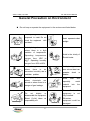
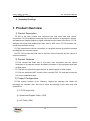
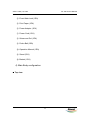
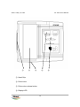
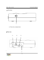
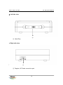
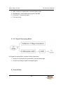
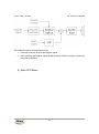
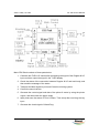
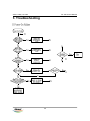
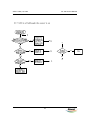
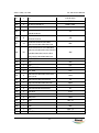
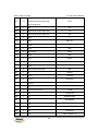
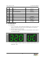
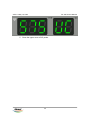
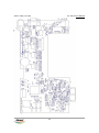
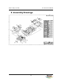
VER 1.0 May 15, 2002 BabyCare Service Manual FC-700 SERVICE MANUAL VER 1.0 May 15, 2002 FC-700 Service Manual BioNet CO., LTD. 2 VER 1.0 May 15, 2002 FC-700 Service Manual Terms of Warranty - This product is manufactured and passed through strict quality control and inspection. - Compensation standard concerning repair, replacement, refund of the product complies with “Consumer’s protection law” noticed by Economic Planning Dept. - FC-700 is warranted by Bionet Co.,Ltd to be free from defects in material and workmanship for two years from date of purchase. - Warranty repair or replacement will be made by Bionet Service Center at no charge during warranty period if properly used under normal condition in accordance with the instructions for use. - In the event of a malfunction or failure during warranty period, customer should inform Bionet Co.,Ltd of the model name, serial number, date of purchase and explanation of failure about the defective equipment. 3 VER 1.0 May 15, 2002 FC-700 Service Manual Definition of Warning, Caution, Note For a special emphasis on agreement, terms are defined as listed below in operation manual. Users should operate the equipment according to all the Warning and Caution instructions. Manufacturer or Sales agency takes no responsibility for any kind of damage or breakdown that is caused by misuse and failure to maintain the equipment.. Warning Be informed that it may cause serious injury or death to the patient, property damage, material losses against the “Warning” sign. Caution Be informed that it may cause no harm in life but lead to injury against the “Caution” sign. 4 VER 1.0 May 15, 2002 FC-700 Service Manual Note Be informed that “Note” sign is used for notifying some important contents relating to installations, use, maintenance for users, but not dangerous. 5 VER 1.0 May 15, 2002 FC-700 Service Manual General Precaution on Environment Do not keep or operate the equipment in the environment listed below. Avoid placing in an area exposed to moist. Do not touch the equipment with wet hand . Avoid exposure to direct sunlight Avoid placing in an area where there is a high variation of temperature. Operating temperature ranges from 10 C to 40 C. Operating humidity ranges from 30% to 85%. Avoid placing in an area where there is an excessive humidity rise or ventilation problem. Avoid placing in an area where chemicals are stored or where there is in danger of gas leakage. Do not disjoint or disassemble the equipment. Bionet Co.Ltd takes no responsibility of it 6 Avoid in the vicinity of Electric heater Avoid placing in an area where there is an excessive shock or vibration. Avoid dust and especially metal material into the equipment Power off when the equipment is not fully installed. Otherwise, equipment could be damaged. VER 1.0 May 15, 2002 FC-700 Service Manual General Precaution on Electric Safety Check the items listed below before operating the equipment. - Be sure that power supply line is appropriate to use. (Power Adaptor Input : 100 - 240V AC, Power Adaptor Output : 18V, 2.5A). - Be sure that the entire connection cable of the system is properly and firmly fixed. Note : The equipment should not be placed in the vicinity of electric generator, X-ray, broadcasting apparatus to eliminate the electric noise during operation. Otherwise, it may cause incorrect result. Self-power line is important for FC-700. To use same power source with other electric instruments may cause incorrect result. Note : FC-700 is classified as listed below ; - This equipment conforms to Class I, Type-BF. - Do not use the equipment in the vicinity of flammable anesthetics and solvents. - The equipment conforms to Class I according to IEC/EN 60601-1 (Safety of Electric Medical Equipment) - This equipment conforms to Level B according to IEC/EN 606011-2 (Electromagnetic Compatibility Requirements) Note : Accessory equipment connected to the analog and digital interfaces must be certified according to the respective IEC standards ( e.g. IEC 950 for data processing equipment and IEC 601-1 for medical equipment ). Furthermore all configuration shall comply with the system standard EN 60601-1-1:1993. If in doubt, consult the technical service department or your local representative. 7 VER 1.0 May 15, 2002 FC-700 Service Manual Safety Symbols ■ The International Electrotechnical Commission (IEC) has established a set of symbols for medical electronic equipment which classify a connection or warn of any potential hazards. The classifications and symbols are shown below. Save these instructions. Symbols contents Isolated patient connection. (IEC 601-1-Type BF) Device part switched off. Device part switched on. Conductor provides a connection between equipment and the potential equalization busbar of the electrical installation External Signal IN/OUT Port . 8 VER 1.0 May 15, 2002 FC-700 Service Manual ======================================================== CONTENTS ======================================================== Terms of Warranty How to reach us Definition of Warning, Caution, Note General Precaution on Environment General Precaution on Electric Safety 1. Product Overview 1) Product Description 2) Product Features 3) Product Configuration 4) Product Installation 2. Function Block Analysis 1) Overall Block Diagram 2) Doppler Signal Processing Block 3) UC Signal Processing Block 4) Sound Block 5) Main CPU Block 3. Troubleshooting 1) Power on failure 2) 7-LED is off although the power is on 3) Sound problem 4) When the printer is not working properly 5) When the keyboard is not working 6) When the serial interface is not working 4. Technical Specification 5. Service Part List 6. Calibration 9 VER 1.0 May 15, 2002 FC-700 Service Manual 7. PCB Board Diagram 8. Assembly Drawings 1. Product Overview 1) Product Description FC-700 is the fetal monitor that measures the fetal heart rate and uterine contraction. FC-700 irradiates ultrasound wave to the abdomen of a pregnant woman, and detects the Doppler frequency signal reflected from the heart of the fetus. FC-700 analyzes this signal and displays the heart rate by LED. Also, FC-700 provides the sound from the heart of fetus. FC-700 measures the uterine contraction of a pregnant woman by pressure sensors and displays the numerical values. And FC-700 records the heart rate of the fetus, fetal movement and the values of uterine contraction. 2) Product Features - FC-700 records the heart rate of the fetus, fetal movement and the uterine contraction of a pregnant woman, and basic information of the equipment with wide A4 Size paper. - FC-700 can use general fax paper as well as thermal paper for fetal monitor. - FC-700 has automatic NST function which records FHR, UC and fetal movement only for the established time. 3) Product Configuration FC-700 system consists of the following. Unpack the package and check the followings are included. Also, be sure to check any damage to the main body and accessories. ① FC-700 main body ② Ultrasound Doppler Probe (1 EA) ③ UC Probe (1EA) 10 VER 1.0 May 15, 2002 FC-700 Service Manual ④ Event Mark Jack (1EA) ⑤ Print Paper (1EA) ⑥ Power Adaptor (1EA) ⑦ Power Cord (1EA) ⑧ Ultrasound Gel (1EA) ⑨ Probe Belt (2EA) ⑩ Operation Manual (1EA) ⑪ Stand (1EA) ⑫ Basket (1EA) 4) Main Body configuration ▣ Top view 11 VER 1.0 May 15, 2002 ① FC-700 Service Manual ② ③ ④ ① Hand Grip ② Printer door ③ Printer door release button ④ Display LED 12 ⑤ VER 1.0 May 15, 2002 FC-700 Service Manual ⑤ Control panel 13 VER 1.0 May 15, 2002 FC-700 Service Manual ▣ Front view ① ① Printer door release button ▣ Rear view ① ② ③ ④ 14 VER 1.0 May 15, 2002 FC-700 Service Manual ① Power adaptor connection port ② Power on/off switch ③ RS-232C serial port ④ Mark Jack connection port 15 VER 1.0 May 15, 2002 FC-700 Service Manual ▣ Left side view ① ① Hand Grip ▣ Right side view ① ① Doppler, UC Probe connection port 16 VER 1.0 May 15, 2002 FC-700 Service Manual Warning To avoid an expected electric shock, do not open the equipment cover or disassemble the equipment. Refer servicing to qualified personnel of Bionet Co., Ltd. 17 VER 1.0 May 15, 2002 FC-700 Service Manual ▣ Control Panel ① ② ④ ① ② ③ ④ ⑤ ⑥ ③ ⑦ ⑧ ⑨ ⑩ Heart rhythm symbol (Green : stable, Red : unstable). Heart rate of the fetus (bpm). UC measurement value. Volume up/down key. During the use of the Menu for setup, this key is used to change the setting value. ⑤ LED of the alarm on/off ⑥ Alarm on/off key. During the use of the Menu for setup, this key is used to set the function of the time and date. ⑦ LED of the power on/off ⑧ Print on/off Key. When setup mode, store the setting value. When out of 18 VER 1.0 May 15, 2002 FC-700 Service Manual print, paper feeding function. ⑨ LED of the print on/off ⑩ Key setting UC value as reference value(10). When setup mode, printing related functions setup. 4) Product Installation ▣ Attention in Installation Pay attention to the following in installing FC-700: ① Use it at the temperature between 10 and 40 degrees centigrade and at the humidity between 30 and 85 percent. ② ③ ④ ⑤ Check plug-in and treat the Probe Cable carefully. Don’t put several plugs in an outlet. Install the main body at the flat place. Avoid using a plug making a noise in plug-in. ⑥ All the setup will be recorded at the interior memory even when it is switched off and then on. ⑦ Be careful, as it is easy to break by the shock. ⑧ Install it away from dust or inflammable things in consideration of the temperature and humidity. ▣ Power Supply Use free voltage of AC between 100 and 250V. If a plug is put in an outlet, the “POWER” LED at operation panel will be turned on green. Within the equipment is a battery to change the date and time even when it is switched off. Use a Type CR2032 3V Lithium Battery. ☞ Note! Don’t throw away batteries carelessly to protect environment, but ask the hospital for the designated places to dump batteries according to proper procedure. 19 VER 1.0 May 15, 2002 FC-700 Service Manual ▣ Plug-in Put the plug in an outlet of 110V or 220V and connect one side of power cable to the power adaptor. If you put the plug of power adaptor in the terminal of power adaptor of the main body of FC-700 and then switch it on, the equipment will work. If the power supply is normal, LED at the operation panel indicating Power On/Off will be turned on green. ▣ Connection of the Probe Cable Connect the Probe Cable to the Probe Cable terminal at the right side of the main body. Connect the Doppler Probe to the “DOP” terminal and the UC Probe to the “UC” terminal. Connect Mark Jack to the “MARK” terminal at the backside of the main body. ▣ Setting of Recording Paper If you release the button to open the printer cover at the front of FC-700 to the right, it will open. Put recording paper with the recording part on the upper side adjusting the paper roll parallel to the print direction and then close the cover. 20 VER 1.0 May 15, 2002 FC-700 Service Manual 2. Functional Block Analysis 1) Overall Block Diagram Overall Block Diagram is mainly divided into an analogue part and digital part. The analogue part consists of the Doppler & UC probe analogue part where receives 21 VER 1.0 May 15, 2002 FC-700 Service Manual bio-signals (Doppler sound & UC) and an analogue-to-digital converter which charges the analogue signals into the digital signals. Also it processes the out of the Doppler & alarm sound. The digital part consists of those parts below. 1. Analogue to digital converting : the signal of FHR & UC, Fetal movement 2. Display : the values of FHR & UC 3. Alarm sound generation 4. Volume control 5. Key scan 6. Print date generation 7. Interface of PC (RS232) 2) Doppler Signal Processing Block Doppler Signal Processing Block consists of those parts below. 1. Control logic : generate the Tx wave using the 16MHz clock 2. Tx : Amplify the signal where receives control logic and then transport the signal to Doppler probe. 22 VER 1.0 May 15, 2002 FC-700 Service Manual 3. AMP : Amplify the signal where receives Doppler probe 4. Demodulation : Demodulate the signal from the AMP 5. LPF & HPF : Filtering the signal 6. Full wave rectify 3) UC Signal Processing Block UC Signal Processing Block consists of those parts below. 1. Amplify UC signal which is measured by using the Strain gage. 2. Convert the analogue signal to the digital signal. 4) Sound Block 23 VER 1.0 May 15, 2002 FC-700 Service Manual Sound Block consists of those parts below. 1. Control the volume level of the Doppler signal 2. After receiving the Doppler signal & Alarm signal, make the output of sound by using the Audio Amp. 5) Main CPU Block 24 VER 1.0 May 15, 2002 FC-700 Service Manual Main CPU Block consists of those parts below. 1. Calculate the FHR & UC values after processing the signal of the Doppler & UC input and then output the signal in the 7-LED display 2. Check the status of the connection between Doppler & UC and main body, and then send the message of the status 3. Transport the Mark signal to print and Central monitoring system 4. Control the sound volume. 5. Generate the control signal and date of the printer & motor by using the printer engine, and then check the paper empty 6. Apply and save the status of Print & Alarm, Time setup after receiving the key input. 7. Generate the check-signal of Watch Dog. 25 VER 1.0 May 15, 2002 FC-700 Service Manual 3. Troubleshooting 26 VER 1.0 May 15, 2002 FC-700 Service Manual A Yes No B 27 VER 1.0 May 15, 2002 FC-700 Service Manual 28 VER 1.0 May 15, 2002 FC-700 Service Manual B No No A No Yes No Yes A Yes A No A Yes Yes No No A B Yes No Yes Yes 29 A VER 1.0 May 15, 2002 FC-700 Service Manual 30 VER 1.0 May 15, 2002 FC-700 Service Manual B No A A Yes A Yes Yes No No A No B Yes 31 VER 1.0 May 15, 2002 FC-700 Service Manual 4. Technical Specification Environmental Specifications Temperature Range Operating : 10 to 40℃ Storage : -10 to 60℃ Relative Humidity Range Operating : 30 ~ 85% Storage : 20 ~ 95% Atmospheric Pressure Range Operating : 70 ~ 106kPa Storage : 70 ~ 106kPa Power Specifications Power Adaptor Input : 100 - 250VAC, 50/60Hz, about 80VA Power Adaptor Output : 16V, 2.8A Power Fail Protection Battery : CR 2032 3V Lithium battery Performance Specifications FHR Measurement Input signal : Ultrasound Pulsed Doppler Ultrasound Frequency : 1.0 MHz Ultrasound Power : <10mW/cm2 FHR Detection Method: Auto Correlation Measurement Range : 50 ~ 240 beats per minutes(BPM) FHR Accuracy : ±1 bpm over normal FHR range UC Measurement Input Source : External Transducer with strain gauge Frequency Response : DC ~ 0.5 Hz 32 VER 1.0 May 15, 2002 FC-700 Service Manual Reference(Zero) Control : One touch switch Measurement Range : 0 ~ 99 units Fetal Movement Measurement Detection Source : Ultrasound Pulsed Doppler Recording Method: ① Spike-like waveform on UC channel denotes relative intensity and duration of Fetal Movement. ② Dot marks between FHR and UC channels when FM intensity exceeds selected threshold. Recorder Recorder Method : Thermal Array Type Resolution: 8(vertical)/10(horizontal) dot/mm Print Speed : 1, 2, 3 cm/min Paper Feeding Function Paper Grid : On/Off Print Contrast : 1, 2 Auto Print Period : 0, 10, 20, 30, 40, 50, 60 Fetal movement: On/Off Display Five 7-Segment LED 2 Channels (FHR, UC) Indicators Heart Rhythm (Green : Stable, Red : Unstable) Alarm On/Off State Print On/Off State AC Power (Green LED) Sound Doppler Sound with Volume Control (8 steps) Alarms Sound : Information Sound : Doppler Probe off, Paper off, Watch Dog, Set-up Data 33 VER 1.0 May 15, 2002 FC-700 Service Manual Storage NST End. Set-up Alarm Upper/Lower Limit Value Alarm check delay time Print Speed Paper Grid Print Contrast Auto Print Period(NST time) Time / Date Fetal Movement On/OFF Fetal Movement Detection Threshold Function Event Mark Function External Link RS232C : Program Down Load, Central (Option) 34 VER 1.0 May 15, 2002 FC-700 Service Manual 5. Service Part List Item Quantity Reference 1 1 BT1 2 3 C1, C141, C142 Part 3V 2032 Lithium Ion Battery 330pF C2,C4,C5,C6,C7,C8,C9,C12, C16,C18,C19,C20,C21,C24, C27,C29,C32,C33,C34,C35, C36,C37,C38,C39,C40,C42, C43,C44,C45,C47,C48,C50, C52,C54,C55,C56,C57,C58, C59,C62,C63,C64,C65,C68, 3 86 C70,C71,C72,C75,C76,C81, 100nF C83,C84,C86,C87,C88,C91, C97,C99,C109,C110,C112, C113,C114,C115,C116,C117, C118,C119,C120,C121,C122, C123,C124,C125,C126,C127, C129,C133,C134,C135,C140, C144,C146,C149,C150,C151 4 7 C3,C41,C66,C67,C78,C82,C85 T10uF C10,C13,C17,C25,C28,C49, 5 20 C61,C90,C92,C93,C94,C95, C96,C103,C104,C105,C106, 1nF C107,C108,C111 6 1 7 12 C11 47nF C14,C15,C30,C51,C53,C77,C79, C80,C98,C100,C101,C102 35 10nF VER 1.0 May 15, 2002 FC-700 Service Manual 8 2 C154,C22 4.7nF 9 1 C23 510pF 10 2 C26,C152 22nF 11 1 C31 3.3nF 12 1 C46 820pF 13 1 C60 15nF 14 3 C69,C147,C148 15 2 C73,C74 22pF 16 1 C89 1uF 17 2 C128,C132 100uF 18 1 C130 T1uF 19 3 C131,C138,C145 470uF 20 1 C136 1000uF 21 1 C137 22uF 22 1 C139 2.2uF 23 1 C143 470nF 24 1 C153 33nF 25 7 D1,D2,D3,D4,D5,D6,D7 1N4148 26 2 D8,D9 1N5158 27 2 G2,G3 Test Point 28 5 H1,H2,H3,H4,H5 29 1 J1 30 2 J2,J3 31 1 J4 5267-3 32 1 J5 8283-14 33 1 J6 HIF3F-26PA-2.54DSA 34 1 J7 5267-6 35 1 J8 5267-4 36 2 J9,J12 5267-2 37 1 J10 HTJ-020-04 38 1 J11 HTJ-035-10 39 2 L1,L2 27uH 40 3 L3,L4,L5 220uH 220nF MH HEADER 7 X 2 LMB0509-6P 36 VER 1.0 May 15, 2002 FC-700 Service Manual 41 1 P1 D-SUB 9 pin 42 1 Q1 MMBT3906 43 6 Q2,Q3,Q4,Q5,Q6,Q7 MMBT3904 44 5 Q8,Q9,Q10,Q11,Q12 DTA123 45 11 46 9 47 14 R1,R2,R8,R14,R17,R20,R23,R37 ,R86,R139,R153 R3,R111,R112,R113,R114,R115, R116,R117,R119 R4,R5,R11,R18,R19,R24,R25, R32,R33,R45,R61,R68,R79,R142 1K 100 20K R6,R7,R10,R12,R13,R15,R28,R29, 48 30 R30,R31,R34,R42,R43,R44,R46,R47 ,R55,R57,R62,R67,R70,R71,R72, 10K R74,R76,R77,R78,R88,R90,R141 49 3 R9,R16,R54 2M 50 1 R21 15K 51 1 R22 470 52 3 R26,R50,R69 68K 53 2 R27,R89 51K 54 9 55 6 R36,R49,R51,R87,R135,R136 56 7 R38,R48,R56,R64,R96,R97,R99 57 1 R39 58 6 R40,R58,R63,R75,R150,R151 59 2 R41,R73 6.8K 60 5 R52,R66,R83,R85,R152 3.3K 61 2 R53,R143 150K 62 1 R59 10K 1% 63 1 R60 430K 64 1 R80 20K 65 1 R81 150K 1% 66 2 R82,R84 30K 1% R35,R65,R91,R92,R98,R129,R130, R131,R132 100K 20 200K 33K 37 2K VER 1.0 May 15, 2002 FC-700 Service Manual R93,R95,R107,R118,R120,R121, 67 14 R122,R123,R124,R125,R126, 4.7K R127,R128,R133 68 1 R94 69 5 R100,R101,R102,R103,R104 10 70 5 R105,R106,R108,R109,R110 330 71 1 R134 1 72 1 R137 33K 1% 73 1 R138 2K 1% 74 1 R140 220 75 2 R144,R145 76 1 R146 56K 77 1 R147 270K 78 1 R148 560K 79 1 R149 180K 80 4 R154,R155,R156,R157 81 1 U1 DG212 82 2 U2,U5 74HC08 83 2 U3,U4 74HC393 84 2 U6,U20 74HC04 85 1 U7 86 5 U8,U9,U14,U15,U33 87 1 U10 CD4051B 88 1 U11 K4S641632D 89 1 U12 S3C44B0X 90 1 U13 OSC 16MHz(3.3V) 91 1 U16 LM1117MPX-2.5 92 1 U17 LM78L05 93 1 U18 LM1117MPX-3.3 75K 120K 680 SST39VF040(PLCC) TL064 38 VER 1.0 May 15, 2002 FC-700 Service Manual 94 2 U19,U29 LM7812 95 1 U21 MM1075 96 5 U22,U23,U24,U25,U26 74HC245 97 1 U27 MAX232CSE 98 1 U28 ULN2064 99 1 U30 TDA2030 100 1 U31 LM2576S-5.0 101 1 U32 PQ2CF1 102 1 X1 32.768KHz 6. Calibration 1) UC calibration 1. Turn on the power with pushing the Reference key. At this time, the display of FHR shows the value of UC and the display of UC shows UC. 2. Open the upper cover of UC probe. 3. Turn the variable resistance toward the counterclockwise until the value of UC shows around 300. 4. Turn the variable resistance toward the clockwise until the value of UC shows 550 ~ 600. 39 VER 1.0 May 15, 2002 FC-700 Service Manual 5. Close the upper cover of UC probe. 40 VER 1.0 May 15, 2002 FC-700 Service Manual 7. PCB Board Diagram 41 VER 1.0 May 15, 2002 FC-700 Service Manual 42 VER 1.0 May 15, 2002 FC-700 Service Manual 8. Assembly Drawings 43


![[U4.92.04] Procédure TEST_FICHIER](http://vs1.manualzilla.com/store/data/006389562_1-6b6086926bffcd67b481cbaaace088d7-150x150.png)