1
Agilent 1260 Infinity
Thermostatted Column
Compartment
User Manual
Agilent Technologies
Notices
© Agilent Technologies, Inc. 2010-2012,
2013
No part of this manual may be reproduced
in any form or by any means (including electronic storage and retrieval or translation
into a foreign language) without prior agreement and written consent from Agilent
Technologies, Inc. as governed by United
States and international copyright laws.
Manual Part Number
G1316-90014
Edition
05/2013
Printed in Germany
Agilent Technologies
Hewlett-Packard-Strasse 8
76337 Waldbronn
This product may be used as a component of an in vitro diagnostic system if the system is registered with
the appropriate authorities and complies with the relevant regulations.
Otherwise, it is intended only for general laboratory use.
Warranty
The material contained in this document is provided “as is,” and is subject to being changed, without notice,
in future editions. Further, to the maximum extent permitted by applicable
law, Agilent disclaims all warranties,
either express or implied, with regard
to this manual and any information
contained herein, including but not
limited to the implied warranties of
merchantability and fitness for a particular purpose. Agilent shall not be
liable for errors or for incidental or
consequential damages in connection
with the furnishing, use, or performance of this document or of any
information contained herein. Should
Agilent and the user have a separate
written agreement with warranty
terms covering the material in this
document that conflict with these
terms, the warranty terms in the separate agreement shall control.
receive no greater than Restricted Rights as
defined in FAR 52.227-19(c)(1-2) (June
1987). U.S. Government users will receive
no greater than Limited Rights as defined in
FAR 52.227-14 (June 1987) or DFAR
252.227-7015 (b)(2) (November 1995), as
applicable in any technical data.
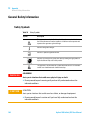
Safety Notices
CAUTION
A CAUTION notice denotes a
hazard. It calls attention to an
operating procedure, practice, or
the like that, if not correctly performed or adhered to, could
result in damage to the product
or loss of important data. Do not
proceed beyond a CAUTION
notice until the indicated conditions are fully understood and
met.
Technology Licenses
The hardware and/or software described in
this document are furnished under a license
and may be used or copied only in accordance with the terms of such license.
Restricted Rights Legend
If software is for use in the performance of a
U.S. Government prime contract or subcontract, Software is delivered and licensed as
“Commercial computer software” as
defined in DFAR 252.227-7014 (June 1995),
or as a “commercial item” as defined in FAR
2.101(a) or as “Restricted computer software” as defined in FAR 52.227-19 (June
1987) or any equivalent agency regulation
or contract clause. Use, duplication or disclosure of Software is subject to Agilent
Technologies’ standard commercial license
terms, and non-DOD Departments and
Agencies of the U.S. Government will
WA R N I N G
A WARNING notice denotes a
hazard. It calls attention to an
operating procedure, practice,
or the like that, if not correctly
performed or adhered to, could
result in personal injury or
death. Do not proceed beyond a
WARNING notice until the indicated conditions are fully understood and met.
Agilent 1260 Infinity TCC User Manual
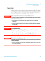
In This Guide…
In This Guide…
This manual covers the Agilent 1260 Infinity Thermostatted Column
Compartments (G1316A TCC).
1 Introduction to the Column Compartment
This chapter gives an introduction to the TCC, instrument overview and
internal connectors.
2 Site Requirements and Specifications
This chapter provides information about site requirements and
specifications for the module.
3 Installing the Column Compartment
This chapter describes the installation of the thermostatted column
compartment.
4 Using the Module
This chapter explains the operational parameters of the module.
5 How to optimize the Column Compartment
This chapter provides information on how to optimize the thermostatted
column compartement.
6 Troubleshooting and Diagnostics
Overview about the troubleshooting and diagnostic features.
7 Error Information
This chapter describes the meaning of error messages, and provides
information on probable causes and suggested actions how to recover from
error conditions.
Agilent 1260 Infinity TCC User Manual
3
In This Guide…
8 Test Functions
This chapter describes the TCC’s built in test functions.
9 Maintenance
This chapter describes the maintenance and repair of the TCC.
10 Parts for Maintenance
This chapter provides information on parts for maintenance.
11 Identifying Cables
This chapter provides information on cables used with the 1260 Infinity
series of HPLC modules.
12 Hardware Information
This chapter describes the detector in more detail on hardware and
electronics.
13 Appendix
This chapter provides addition information on safety, legal and web.
4
Agilent 1260 Infinity TCC User Manual
Contents
Contents
1 Introduction to the Column Compartment
Introduction 10
System Overview 13
Column-Identification System 16
Column Switching Valve (Optional)
9
18
2 Site Requirements and Specifications
21
Site Requirements 22
Physical Specifications 25
Performance Specifications 26
3 Installing the Column Compartment
27
Unpacking the Column Compartment 28
Optimizing the Stack Configuration 29
Installation Information on Leak and Waste Handling
Installing the Column Compartment 38
Flow Connections of the Column Compartment 41
Placing Columns 45
4 Using the Module
34
47
Leak and Waste Handling
Solvent Information 49
48
5 How to optimize the Column Compartment
51
Optimizing the Performance of your Column Compartment
6 Troubleshooting and Diagnostics
53
Overview of the Module’s Indicators and Test Functions
Status Indicators 56
Available Tests depending on User Interfaces 58
Agilent Lab Advisor Software 59
Agilent 1260 Infinity TCC User Manual
52
54
5
Contents
7 Error Information
61
What Are Error Messages 62
General Error Messages 63
TCC Error Messages 69
8 Test Functions
77
Thermostat Function Test 78
Pressure Test 81
Column Thermostat Temperature Calibration
9 Maintenance
82
91
Warnings and Cautions 92
Introduction to Maintenance 94
Overview of Maintenance 95
Cleaning the Module 96
Changing Column Identification Tags 97
Replacing Head Parts of Column Switching Valve
Correcting Leaks 102
Replacing the Module’s Firmware 103
10 Parts for Maintenance
105
Column Switching Valve 2 Position/6 Port
Kits 107
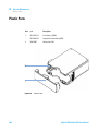
Plastic Parts 108
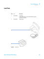
Leak Parts 109
11 Identifying Cables
106
111
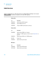
Cable Overview 112
Analog Cables 114
Remote Cables 116
BCD Cables 119
CAN/LAN Cables 121
External Contact Cable 122
Agilent Module to PC 123
Agilent 1200 Module to Printer
6
99
124
Agilent 1260 Infinity TCC User Manual
Contents
12 Hardware Information
125
Firmware Description 126
Electrical Connections 129
Interfaces 131
Setting the 8-bit Configuration Switch (without On-Board LAN)
Instrument Layout 142
13 Appendix
138
143
General Safety Information 144
The Waste Electrical and Electronic Equipment (WEEE) Directive
(2002/96/EC) 147
Lithium Batteries Information 148
Radio Interference 149
Sound Emission 150
Use of Solvents 151
Agilent Technologies on Internet 152
Agilent 1260 Infinity TCC User Manual
7
Contents
8
Agilent 1260 Infinity TCC User Manual
Agilent 1260 Infinity TCC User Manual
1
Introduction to the Column
Compartment
Introduction
10
System Overview 13
Leak and Waste Handling
13
Column-Identification System
16
Column Switching Valve (Optional)
18
This chapter gives an introduction to the TCC, instrument overview and internal
connectors.
Agilent Technologies
9
1
Introduction to the Column Compartment
Introduction
Introduction
Main Features
The Agilent 1260 Infinity Thermostatted Column Compartment is a
stackable temperature- controlled column compartment for LC. It is used
for heating and cooling to meet extreme requirements of retention time
reproducibility.
The main features are:
• Peltier heating and cooling from 10 degrees below ambient up to 80 °C
with high heating and cooling speeds for maximum application
flexibility and stability.
• Holds up to three 30 cm columns and optimized design gives minimum
dead volumes and maximum efficiency.
• Two independently programmable heat exchangers contribute volumes
of only 3 µL and 6 µL.
• Electronic column- identification module as standard for GLP
documentation of column type and major column parameters.
• Optional high- quality Rheodyne® column switching valve with ceramic
stator- face assemblies for prolonged lifetime.
For specifications, see “Performance Specifications” on page 26.
10
Agilent 1260 Infinity TCC User Manual
1
Introduction to the Column Compartment
Introduction
System Overview
The Concept of Heating and Cooling
The design of this thermostatted column compartment uses column
heating and cooling devices with Peltier elements. The solvent entering the
column compartment is heated up or cooled down to a settable
temperature with two low- volume heat exchangers (3 µl on left side, 6 µl
on right side), made of a short piece of capillary 0.17 mm i.d. leading
through a heat exchanger. The heat exchanger is designed such that it can
function simultaneously as an air heater. The shape of the heat exchanger
surface allows the area around the column to be kept at a similar
temperature level as the liquid running through the column. This is done
by thermal convection and radiation between the heat exchanger fins. This
design ensures that the column and the solvent flowing through it are
almost at the same temperature.
Actual temperature control is accomplished at the heat exchanger. The
solvent cools down or heats up on its transfer from the heating block to
the column inlet. This depends on several factors: flow rate, setpoint
temperature, ambient temperature and column dimensions.
In a flow- through temperature regulation system, there are necessarily
slightly different temperatures at different positions. If, for example, the
temperature set by the user is 40 °C, then the heat exchanger is regulated
to a temperature of 40.8 °C which is different by a certain offset (here
0.8 °C). The solvent temperature at the column entry would be about
39 °C.
The actual temperature displayed on the user interface is always the
derived temperature taken at the heat exchanger, corrected by the offset
explained above.
Any type of heated column compartment brings one important
consequence for column temperature equilibration. Before an equilibrium
is reached, the whole mass of column, column packing, and solvent volume
inside the column has to be brought to the selected temperature. This
depends on several factors: flow rate, setpoint temperature, ambient
temperature and column dimensions. The higher the flow rate, the faster
the column equilibrates (due to thermostatted mobile phase).
Agilent 1260 Infinity TCC User Manual
11
1
Introduction to the Column Compartment
Introduction
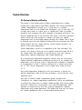
Figure 1 on page 12 shows a setpoint temperature of 40 °C. Some time
after entering the setpoint the heat exchanger has reached its temperature
and the control activity starts. The TEMPERATURE NOT READY signal will be
cancelled 20 seconds after the sensed temperature was within a range of
± 0.5 °C of the setpoint (other values can be set via the user interface).
However this does not necessarily mean that the column has already
reached the correct temperature. The equilibration of the column may take
longer. Stability of the pressure signal is a good indication for equilibrium.
IZbeZgVijg8
=ZViZmX]Vc\ZgiZbeZgVijgZ
8dajbciZbeZgVijgZ
:mVbeaZ[dgV[adlgViZd[*ba$b^cd[lViZg
I^bZb^c
Figure 1
Equilibration of Heat Exchanger and Column Temperature
The temperature calibration and verification is described in the Service
Manual.
12
Agilent 1260 Infinity TCC User Manual
Introduction to the Column Compartment
System Overview
1
System Overview
Leak and Waste Handling
The 1200 Infinity Series has been designed for safe leak and waste
handling. It is important that all security concepts are understood and
instructions are carefully followed.
Agilent 1260 Infinity TCC User Manual
13
1
Introduction to the Column Compartment
System Overview
&
6
'
7
8
(
)
*
+
,
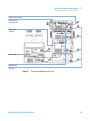
Figure 2
14
Leak and waste handling concept (overview - typical stack configuration as an
example)
Agilent 1260 Infinity TCC User Manual
1
Introduction to the Column Compartment
System Overview
The solvent cabinet (1) is designed to store a maximum volume of 6 L
solvent. The maximum volume for an individual bottle stored in the
solvent cabinet should not exceed 2.5 L. For details, see the usage
guideline for the Agilent 1200 Infinity Series Solvent Cabinets (a printed
copy of the guideline has been shipped with the solvent cabinet, electronic
copies are available on the Internet).
The leak pan (2) (individually designed in each module) guides solvents to
the front of the module. The concept covers also leakages on internal
parts (e.g. the detector’s flow cell). The leak sensor in the leak pan stops
the running system as soon as the leak detection level is reached.
The leak pan's outlet port (3, A) guides excessive overfill from one module
to the next, as the solvent flows into the next module’s leak funnel (3, B)
and the connected corrugated waste tube (3, C). The corrugated waste
tube guides the solvent to the next lower positioned module’s leak tray
and sensor.
The waste tube of the sampler’s needle wash port (4) guides solvents to
waste.
The condense drain outlet of the autosampler cooler (5) guides condensate
to waste.
The waste tube of the purge valve (6) guides solvents to waste.
The waste tube connected to the leak pan outlet on each of the bottom
instruments (7) guides the solvent to a suitable waste container.
Agilent 1260 Infinity TCC User Manual
15
1
Introduction to the Column Compartment
Column-Identification System
Column-Identification System
The Agilent 1260 Infinity Thermostatted Column Compartment is equipped
with a column- identification system. It allows to read and write
column- specific information to and from an optionally available
column- identification tag (part of the HPLC starter- kits available for 1220,
1260 and 1290 Infinity pumps or seperately as P/N 5062- 8588).
6ciZccVh
8dajbc"^YZci^[^XVi^dciV\
8dajbcXa^e
Figure 3
Column-Identification System
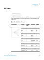
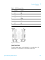
Table 1 on page 17 shows the information that can be stored. The
information fields can be edited via the user interface.
16
Agilent 1260 Infinity TCC User Manual
Introduction to the Column Compartment
Column-Identification System
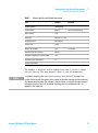
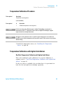
Table 1
1
Column-Identification Module Information
Item
Example
Product number
79916OD-552
Serial number
950522
Batch number
1675
Geometry
100 mm × 2.1 mm
Stationary phase
ODS Hypersil
Particle size
10 µm
Number of injections
1267
Maximum pressure allowed
400 bar
Maximum temperature recommended
70 °C
Maximum pH recommended
12
Comment
Date of manufacturing
See below.
Column void volume
The number of injections will be updated each run to create a column
lifecycle (history). The user interface allows to edit all information.
NOTE
If a column switching valve (see “Column Switching Valve (Optional)” on page 18) is
installed in the module, the update of the number of injections depends on the position of
the column switching valve. For example, if the left column is selected, the right column is
not updated, and vice versa. If no column switching valve is installed both sides are
updated at the same time.
Agilent 1260 Infinity TCC User Manual
17
1
Introduction to the Column Compartment
Column Switching Valve (Optional)
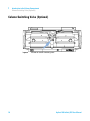
Column Switching Valve (Optional)
Figure 4
18
Location of Column Switching Valve
Agilent 1260 Infinity TCC User Manual
Introduction to the Column Compartment
Column Switching Valve (Optional)
1
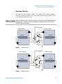
Two Column Selection
The valve can select either column 1 or column 2. The offline column is
sealed by connecting head to tail. Switching should be done when the flow
is off and the pressure is zero.
NOTE
Before switching the valve, switch off the pump or set the flow to zero. Keeping the flow on
while the valve is switched can cause exceeding the maximum pressure. This will stop
method or sequence execution.
;gdbVjidhVbeaZg
=ZViZgVhhZbWan&
=ZViZgVhhZbWan'
8dajbc&
8dajbc'
IdYZiZXidg
Figure 5
Column 1 Active
;gdbVjidhVbeaZg
=ZViZgVhhZbWan'
=ZViZgVhhZbWan&
8dajbc'
8dajbc&
IdYZiZXidg
Figure 6
Column 2 Active
Agilent 1260 Infinity TCC User Manual
19
1
Introduction to the Column Compartment
Column Switching Valve (Optional)
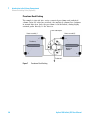
Precolumn Back-flushing
The sample is injected into series- connected precolumn and analytical
column. After the valve has switched, the analytical column flow continues
in normal direction. Only the precolumn is back- flushed, eluting highly
retained peaks directly to the detector.
;gdbVjidhVbeaZg
=ZViZgVhhZbWan'
=ZViZgVhhZbWan&
EgZXdajbc
6cVani^XVa
8dajbc
IdYZiZXidg
Figure 7
20
Precolumn Back-flushing
Agilent 1260 Infinity TCC User Manual
Agilent 1260 Infinity TCC User Manual
2
Site Requirements and Specifications
Site Requirements
22
Physical Specifications
25
Performance Specifications
26
This chapter provides information about site requirements and specifications
for the module.
Agilent Technologies
21
2
Site Requirements and Specifications
Site Requirements
Site Requirements
A suitable environment is important to ensure optimal performance of the
instrument.
Power Considerations
The module power supply has wide ranging capability. It accepts any line
voltage in the range described in Table 2 on page 25. Consequently there
is no voltage selector in the rear of the module. There are also no
externally accessible fuses, because automatic electronic fuses are
implemented in the power supply.
WA R N I N G
Hazard of electrical shock or damage of your instrumentation
can result, if the devices are connected to a line voltage higher than specified.
➔ Connect your instrument to the specified line voltage only.
WA R N I N G
The module is partially energized when switched off, as long as the power cord is
plugged in.
Repair work at the module can lead to personal injuries, e.g. electrical shock, when
the cover is opened and the module is connected to power.
➔ Always unplug the power cable before opening the cover.
➔ Do not connect the power cable to the instrument while the covers are removed.
CAUTION
Inaccessible power plug.
In case of emergency it must be possible to disconnect the instrument from the power
line at any time.
➔ Make sure the power connector of the instrument can be easily reached and
unplugged.
➔ Provide sufficient space behind the power socket of the instrument to unplug the
cable.
22
Agilent 1260 Infinity TCC User Manual
2
Site Requirements and Specifications
Site Requirements
Power Cords
Different power cords are offered as options with the module. The female
end of all power cords is identical. It plugs into the power- input socket at
the rear. The male end of each power cord is different and designed to
match the wall socket of a particular country or region.
WA R N I N G
Absence of ground connection or use of unspecified power cord
The absence of ground connection or the use of unspecified power cord can lead to
electric shock or short circuit.
➔ Never operate your instrumentation from a power outlet that has no ground
connection.
➔ Never use a power cord other than the Agilent Technologies power cord designed
for your region.
WA R N I N G
Use of unsupplied cables
Using cables not supplied by Agilent Technologies can lead to damage of the
electronic components or personal injury.
➔ Never use cables other than the ones supplied by Agilent Technologies to ensure
proper functionality and compliance with safety or EMC regulations.
WA R N I N G
Unintended use of supplied power cords
Using power cords for unintended purposes can lead to personal injury or damage of
electronic equipment.
➔ Never use the power cords that Agilent Technologies supplies with this instrument
for any other equipment.
Agilent 1260 Infinity TCC User Manual
23
2
Site Requirements and Specifications
Site Requirements
Bench Space
The module dimensions and weight (see Table 2 on page 25) allow you to
place the module on almost any desk or laboratory bench. It needs an
additional 2.5 cm (1.0 inches) of space on either side and approximately
8 cm (3.1 inches) in the rear for air circulation and electric connections.
If the bench shall carry a complete HPLC system, make sure that the
bench is designed to bear the weight of all modules.
The module should be operated in a horizontal position.
Condensation
CAUTION
Condensation within the module
Condensation will damage the system electronics.
➔ Do not store, ship or use your module under conditions where temperature
fluctuations could cause condensation within the module.
➔ If your module was shipped in cold weather, leave it in its box and allow it to warm
slowly to room temperature to avoid condensation.
24
Agilent 1260 Infinity TCC User Manual
2
Site Requirements and Specifications
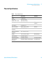
Physical Specifications
Physical Specifications
Table 2
Physical Specifications
Type
Specification
Weight
11.2 kg (22 lbs)
Dimensions
(height × width × depth)
140 x 345 x 435 mm
(5.5 x 13.5 x 17 inches)
Line voltage
100 – 240 VAC, ± 10 %
Line frequency
50 or 60 Hz, ± 5 %
Power consumption
320 VA / 150W / 512 BTU
Ambient operating
temperature
0–55 °C (32–131 °F)
Ambient non-operating
temperature
-40 – 70 °C (-40 – 158 °F)
Humidity
< 95 % r.h. at 40 °C (104 °F)
Operating altitude
Up to 2000 m (6562 ft)
Non-operating altitude
Up to 4600 m (15091 ft)
For storing the module
Safety standards:
IEC, CSA, UL
Installation category II, Pollution degree 2
For indoor use only.
Agilent 1260 Infinity TCC User Manual
Comments
Wide-ranging
capability
Maximum
Non-condensing
25
2
Site Requirements and Specifications
Performance Specifications
Performance Specifications
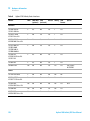
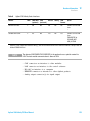
Table 3
Performance Specifications Thermostatted Column Compartment
Type
Specification
Comments
Temperature range
10 degrees below ambient to 80 °C
up to 80 °C: flow rates up to 5 mL/min
NOTE
26
Temperature stability
± 0.15 °C
Temperature accuracy
± 0.8 °C
± 0.5 °C
With calibration
Column capacity
Three 30 cm
Warm-up/cool-down
time
5 minutes from ambient to 40 °C
10 minutes from 40 – 20 °C
Dead volume
3 µL left heat exchanger
6 µL right heat exchanger
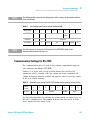
Communications
Controller-area network (CAN), RS-232C,
APG Remote: ready, start, stop and
shut-down signals, LAN via other 1260
Infinity module
Safety and
maintenance
Extensive diagnostics, error detection
and display (through Instant Pilot and
Agilent data system), leak detection, safe
leak handling, leak output signal for
shutdown of pumping system. Low
voltages in major maintenance areas.
GLP features
Column-identification module for GLP
documentation of column type.
Housing
All materials recyclable
All specifications are valid for distilled water at ambient temperature (25 °C), set point at
40 °C and a flow range from 0.2 –5 mL/min.
Agilent 1260 Infinity TCC User Manual
Agilent 1260 Infinity TCC User Manual
3
Installing the Column Compartment
Unpacking the Column Compartment
Delivery Checklist 28
Optimizing the Stack Configuration
One Stack Configuration 29
Two Stack Configuration 32
28
29
Installation Information on Leak and Waste Handling
Installing the Column Compartment
38
Flow Connections of the Column Compartment
Placing Columns 45
Column-Identification Tag
Column Clip 46
34
41
45
This chapter describes the installation of the thermostatted column
compartment.
Agilent Technologies
27
3
Installing the Column Compartment
Unpacking the Column Compartment
Unpacking the Column Compartment
If the delivery packaging shows signs of external damage, please call your
Agilent Technologies sales and service office immediately. Inform your
service representative that the instrument may have been damaged during
shipment.
CAUTION
"Defective on arrival" problems
If there are signs of damage, please do not attempt to install the module. Inspection by
Agilent is required to evaluate if the instrument is in good condition or damaged.
➔ Notify your Agilent sales and service office about the damage.
➔ An Agilent service representative will inspect the instrument at your site and
initiate appropriate actions.
Delivery Checklist
Ensure all parts and materials have been delivered with the module. The
delivery checklist is shown below. Please report missing or damaged parts
to your local Agilent Technologies sales and service office.
Table 4
28
Column Compartment Delivery Checklist
Description
Quantity
Thermostatted column compartment
1
Power cable
1
CAN cable
1
Column switching valve
optional
User Manual (on User Documentation DVD)
1
Accessory kit (see “Accessory Kit” on page 107)
1
Agilent 1260 Infinity TCC User Manual
3
Installing the Column Compartment
Optimizing the Stack Configuration
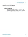
Optimizing the Stack Configuration
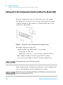
One Stack Configuration
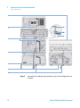
Ensure optimum performance by installing the modules of the Agilent
1260 Infinity LC in the following configuration (see Figure 8 on page 30
and Figure 9 on page 31). This configuration optimizes the flow path for
minimum delay volume and minimizes the bench space required.
Agilent 1260 Infinity TCC User Manual
29
3
Installing the Column Compartment
Optimizing the Stack Configuration
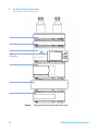
HdakZciXVW^cZi
KVXjjbYZ\VhhZg
Ejbe
AdXVa
JhZg>ciZg[VXZ
6jidhVbeaZg
8dajbcXdbeVgibZci
9ZiZXidg
Figure 8
30
Recommended Stack Configuration (Front View)
Agilent 1260 Infinity TCC User Manual
Installing the Column Compartment
Optimizing the Stack Configuration
3
68edlZg
GZbdiZXVWaZ
86C7jhXVWaZid
adXVajhZg^ciZg[VXZ
86C7jhXVWaZ
A6CidA8
8]ZbHiVi^dcadXVi^dc
YZeZcYhdcYZiZXidg
6cVad\YZiZXidg
h^\cVa
&dg'djiejiheZg
YZiZXidg
Figure 9
Recommended Stack Configuration (Rear View)
Agilent 1260 Infinity TCC User Manual
31
3
Installing the Column Compartment
Optimizing the Stack Configuration
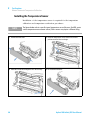
Two Stack Configuration
To avoid excessive height of the stack when the autosampler thermostat is
added to the system it is recommended to form two stacks. Some users
prefer the lower height of this arrangement even without the autosampler
thermostat. A slightly longer capillary is required between the pump and
autosampler. See Figure 10 on page 32 and Figure 11 on page 33.
>chiVciE^adi
9ZiZXidg
8dajbcXdbeVgibZci
6jidhVbeaZg
I]ZgbdhiVi[dgi]Z6AH
dei^dcVa
HdakZciXVW^cZi
9Z\VhhZgdei^dcVa
Ejbe
Figure 10
32
Two stack configuration (front view)
Agilent 1260 Infinity TCC User Manual
Installing the Column Compartment
Optimizing the Stack Configuration
3
A6CidXdcigdahd[ilVgZ
86C7jhXVWaZ
id>chiVciE^adi
I]ZgbdXVWaZ
dei^dcVa
68EdlZg
GZbdiZXVWaZ
68EdlZg
86C7jhXVWaZ
68EdlZg
Figure 11
Two stack configuration (rear view)
Agilent 1260 Infinity TCC User Manual
33
3
Installing the Column Compartment
Installation Information on Leak and Waste Handling
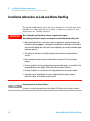
Installation Information on Leak and Waste Handling
The Agilent 1200 Infinity Series has been designed for safe leak and waste
handling. It is important that all security concepts are understood and
instructions are carefully followed.
WA R N I N G
Toxic, flammable and hazardous solvents, samples and reagents
The handling of solvents, samples and reagents can hold health and safety risks.
➔ When working with these substances observe appropriate safety procedures (for
example by wearing goggles, safety gloves and protective clothing) as described in
the material handling and safety data sheet supplied by the vendor, and follow good
laboratory practice.
➔ The volume of substances should be reduced to the minimum required for the
analysis.
➔ Never exceed the maximal permissible volume of solvents (6 L) in the solvent
cabinet.
➔ Do not use bottles that exceed the maximum permissible volume as specified in the
usage guideline for the Agilent 1200 Infinity Series Solvent Cabinets.
➔ Arrange the bottles as specified in the usage guideline for the solvent cabinet.
➔ A printed copy of the guideline has been shipped with the solvent cabinet,
electronic copies are available on the Internet.
NOTE
Recommendations for Solvent Cabinet
For details, see the usage guideline for the Agilent 1200 Infinity Series Solvent Cabinets.
34
Agilent 1260 Infinity TCC User Manual
Installing the Column Compartment
Installation Information on Leak and Waste Handling
3
&
6
'
7
8
(
)
*
+
,
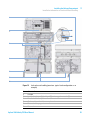
Figure 12
1
2
3
4
5
6
7
Leak and waste handling (overview - typical stack configuration as an
example)
Solvent cabinet
Leak pan
Leak pan's outlet port (A), leak funnel (B) and corrugated waste tube (C)
Waste tube of the sampler’s needle wash
Condense drain outlet of the autosampler cooler
Waste tube of the purge valve
Waste tube
Agilent 1260 Infinity TCC User Manual
35
3
Installing the Column Compartment
Installation Information on Leak and Waste Handling
1 Stack the modules according to the adequate stack configuration.
The leak pan outlet of the upper module must be vertically positioned
above the leak tray of the lower module, see Figure 12 on page 35.
2 Connect data and power cables to the modules, see section Installing
the Module below.
3 Connect capillaries and tubes to the modules, see section Flow
Connections to the module below or the relevant system manual.
WA R N I N G
Toxic, flammable and hazardous solvents, samples and reagents
➔ Keep solvent path free from blockages.
➔ Keep the flow path closed (in case the pump in the system is equipped with a
passive inlet valve, solvent may leak out due to hydrostatic pressure, even if your
instrument is off).
➔ Avoid loops.
➔ Tubes must not sag.
➔ Do not bend tubes.
➔ Do not immerse tube end in waste liquid.
➔ Do not intubate tubes in other tubes.
➔ For correct tubing follow instructions on label attached to the module.
36
Agilent 1260 Infinity TCC User Manual
Installing the Column Compartment
Installation Information on Leak and Waste Handling
Figure 13
3
Warning label (illustration for correct waste tubing)
Agilent 1260 Infinity TCC User Manual
37
3
Installing the Column Compartment
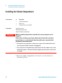
Installing the Column Compartment
Installing the Column Compartment
Parts required
Preparations
#
Description
1
Column compartment
1
Power cord
1
For other cables see text below
Locate bench space.
Provide power connections.
Unpack the Column compartment.
WA R N I N G
Module is partially energized when switched off, as long as the power cord is
plugged in.
Risk of stroke and other personal injury. Repair work at the module can lead to
personal injuries, e. g. shock hazard, when the module cover is opened and the
instrument is connected to power.
➔ Never perform any adjustment, maintenance or repair of the module with the top
cover removed and with the power cord plugged in.
➔ The security lever at the power input socket prevents that the module cover is taken
off when line power is still connected. Never plug the power line back in when cover
is removed.
1 Place the column compartment in the stack or on the bench in a
horizontal position.
38
Agilent 1260 Infinity TCC User Manual
Installing the Column Compartment
Installing the Column Compartment
3
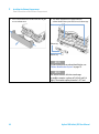
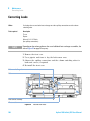
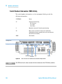
2 Ensure the power switch at the front of the column compartment is
OFF.
HiVijh^cY^XVidg
\gZZc$nZaadl$gZY
A^cZedlZghl^iX]
l^i]\gZZca^\]i
Figure 14
Front View of the Thermostatted Column Compartment
3 Connect the power cable to the power connector at the rear of the
column compartment.
4 Connect the CAN cable to other Agilent 1260 Infinity modules.
5 If Agilent ChemStation is the controller, connect the LAN connection to
the LAN interface board in the detector.
NOTE
If an Agilent DAD/MWD/FLD is in the system, the LAN should be connected to the
DAD/MWD/FLD (due to higher data load).
6 Connect the APG Remote cable (optional) for non- Agilent 1260 Infinity
modules.
Agilent 1260 Infinity TCC User Manual
39
3
Installing the Column Compartment
Installing the Column Compartment
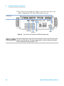
7 Turn ON power by pushing the button at the lower left side of the
column compartment. The status LED should be green.
HZXjg^inaZkZg
8dc[^\jgVi^dchl^iX]
86C
6E<GZbdiZ
GH"'('8
Figure 15
NOTE
40
EdlZg
Rear View of the Thermostatted Column Compartment
The column compartment is turned on when the line power switch is pressed and the green
indicator lamp is illuminated. The column compartment is turned off when the line power
switch is protruding and the green light is OFF.
Agilent 1260 Infinity TCC User Manual
Installing the Column Compartment
Flow Connections of the Column Compartment
3
Flow Connections of the Column Compartment
Parts required
Preparations
WA R N I N G
#
Description
1
Other modules
1
Parts from Accessory Kit
1
Two wrenches 1/4 – 5/16 inch for capillary connections
Install the column compartment
Toxic, flammable and hazardous solvents, samples and reagents
The handling of solvents, samples and reagents can hold health and safety risks.
➔ When working with these substances observe appropriate safety procedures (for
example by wearing goggles, safety gloves and protective clothing) as described in
the material handling and safety data sheet supplied by the vendor, and follow good
laboratory practice.
➔ The volume of substances should be reduced to the minimum required for the
analysis.
➔ Do not operate the instrument in an explosive atmosphere.
Agilent 1260 Infinity TCC User Manual
41
3
Installing the Column Compartment
Flow Connections of the Column Compartment
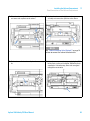
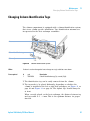
1 Press release buttons and remove front cover to gain
access to heater area.
2 The column compartment is equipped with an
column-identification system that can read column tags.
6ciZccVh
8dajbciV\
8dajbcXa^e
NOTE
For more information on column identification, see
“Column-Identification System” on page 16 .
NOTE
The internal volumes of the heat exchanger
assemblies comprise a volume of 3 µl (left) and 6 µl
(right). The internal capillary diameter is 0.17 mm.
42
Agilent 1260 Infinity TCC User Manual
Installing the Column Compartment
Flow Connections of the Column Compartment
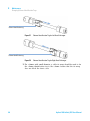
3 Place the column on the left heat exchanger assembly
and connect the capillaries to the column.
3
4 Or place the column on the right heat exchanger
assembly and connect the capillaries to the column.
;gdbVjidhVbeaZg
8a^e
IdYZiZXidg
NOTE
See “Column Switching Valve (Optional)” on page 18
on how to connect the column selection valve.
5 Fix the column with the column clip from the accessory
kit.
Agilent 1260 Infinity TCC User Manual
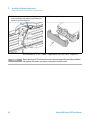
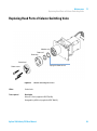
6 If the column compartment is not part of an Agilent 1200
Infinity Series system, or if an Agilent 1200 Infinity Series
autosampler is located on top, connect the corrugated
tubing to the waste outlet.
43
3
Installing the Column Compartment
Flow Connections of the Column Compartment
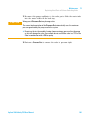
7 Route tubings from modules above through the openings 8 Put the front cover back in place.
in the funnel holder (top) and the plastic bottom part.
Remove small plastic plugs first.
The installation of the column compartment has now been completed.
NOTE
44
Always operate the TCC with the front cover in place for proper thermostatting conditions
and to protect the column area against strong drafts from the ouside.
Agilent 1260 Infinity TCC User Manual
Installing the Column Compartment
Placing Columns
3
Placing Columns
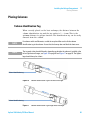
Column-Identification Tag
When correctly placed on the heat exchanger, the distance between the
column identification tag and the tag reader is 1 – 2 mm. This is the
optimum distance for proper function. The identification tag can be easily
removed from the column.
NOTE
For columns with small diameter, a cable tie wrap should be used to fix the column
identification tag to the column. Assure that the tie wrap does not block the front cover.
NOTE
The tag needs to be placed differently, depending on whether the column is installed at the
left or right heat exchanger, see Figure 16 on page 45 and Figure 17 on page 45. The Agilent
logo should always be at front.
8dajbc"^YZci^[^XVi^dciV\
Figure 16
Column-Identification Tag for Left Heat Exchanger
8dajbc"^YZci^[^XVi^dciV\
Figure 17
Column-Identification Tag for Right Heat Exchanger
Agilent 1260 Infinity TCC User Manual
45
3
Installing the Column Compartment
Placing Columns
Column Clip
For better positioning of the column on the heat exchanger a column clip
is available (see “Accessory Kit” on page 107).
Figure 18
46
Column clip
Agilent 1260 Infinity TCC User Manual
Agilent 1260 Infinity TCC User Manual
4
Using the Module
Leak and Waste Handling
Solvent Information
48
49
This chapter explains the operational parameters of the module.
Agilent Technologies
47
4
Using the Module
Leak and Waste Handling
Leak and Waste Handling
WA R N I N G
Toxic, flammable and hazardous solvents, samples and reagents
The handling of solvents, samples and reagents can hold health and safety risks.
➔ When working with these substances observe appropriate safety procedures (for
example by wearing goggles, safety gloves and protective clothing) as described in
the material handling and safety data sheet supplied by the vendor, and follow good
laboratory practice.
➔ The volume of substances should be reduced to the minimum required for the
analysis.
➔ Do not operate the instrument in an explosive atmosphere.
➔ Never exceed the maximal permissible volume of solvents (6 L) in the solvent
cabinet.
➔ Do not use bottles that exceed the maximum permissible volume as specified in the
usage guideline for the Agilent 1200 Infinity Series Solvent Cabinets.
➔ Arrange the bottles as specified in the usage guideline for the solvent cabinet.
➔ A printed copy of the guideline has been shipped with the solvent cabinet,
electronic copies are available on the Internet.
➔ The residual free volume in the appropriate waste container must be large enough
to collect the waste liquid.
➔ Check the filling level of the waste container regularly.
➔ To achieve maximal safety, check the correct installation regularly.
NOTE
Recommendations for Solvent Cabinet
For details, see the usage guideline for the Agilent 1200 Infinity Series Solvent Cabinets.
For details on correct installation, see “Installation Information on Leak
and Waste Handling” on page 34.
48
Agilent 1260 Infinity TCC User Manual
4
Using the Module
Solvent Information
Solvent Information
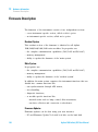
Observe the following recommendations on the use of solvents.
• Follow recommendations for avoiding the growth of algae, see pump
manuals.
• Small particles can permanently block capillaries and valves. Therefore,
always filter solvents through 0.4 µm filters.
• Avoid or minimize the use of solvents that may corrode parts in the
flow path. Consider specifications for the pH range given for different
materials like flow cells, valve materials etc. and recommendations in
subsequent sections.
Agilent 1260 Infinity TCC User Manual
49
4
50
Using the Module
Solvent Information
Agilent 1260 Infinity TCC User Manual
Agilent 1260 Infinity TCC User Manual
5
How to optimize the Column
Compartment
Optimizing the Performance of your Column Compartment
52
This chapter provides information on how to optimize the thermostatted
column compartement.
Agilent Technologies
51
5
How to optimize the Column Compartment
Optimizing the Performance of your Column Compartment
Optimizing the Performance of your Column Compartment
For best performance results of the column compartment:
• Use short connection capillaries and place them close to the heat
exchanger. This will reduce heat dissipation and external
band- broadening.
• Use the left heat exchanger for small volume columns, for example, 2 –
3 mm i.d. columns at flow rates of less than 200 µL/min.
• For even lower band- broadening, the heat exchanger can be by- passed
and the column is placed well between the heat exchanger fins.
• Keep the left and right heat exchanger temperature the same unless you
do specific applications.
• Assure that the front cover is always closed.
52
Agilent 1260 Infinity TCC User Manual
Agilent 1260 Infinity TCC User Manual
6
Troubleshooting and Diagnostics
Overview of the Module’s Indicators and Test Functions
54
Status Indicators 56
Power Supply Indicator 56
Module Status Indicator 57
Available Tests depending on User Interfaces
Agilent Lab Advisor Software
58
59
Overview about the troubleshooting and diagnostic features.
Agilent Technologies
53
6
Troubleshooting and Diagnostics
Overview of the Module’s Indicators and Test Functions
Overview of the Module’s Indicators and Test Functions
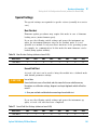
Status Indicators
The module is provided with two status indicators which indicate the
operational state (prerun, run, and error states) of the module. The status
indicators provide a quick visual check of the operation of the module.
Error Messages
In the event of an electronic, mechanical or hydraulic failure, the module
generates an error message in the user interface. For each message, a
short description of the failure, a list of probable causes of the problem,
and a list of suggested actions to fix the problem are provided (see
chapter Error Information).
Test Functions
A series of test functions are available for troubleshooting and operational
verification after exchanging internal components (see Tests and
Calibrations).
Thermostat Diagnostic Test
The Thermostat Diagnostic Test evaluates the heating and cooling efficiency of
the two peltier elements.
54
Agilent 1260 Infinity TCC User Manual
Troubleshooting and Diagnostics
Overview of the Module’s Indicators and Test Functions
6
Temperature Calibration and Verification
The temperature calibration and verification procedure enables the
instrument temperature to be measured against an external, calibrated
measuring device. Normally, temperature calibration is not required
throughout the lifetime of the instrument. However, in order to comply
with local regulatory requirements, calibration and verification may be
required.
The following sections describe these functions in detail.
Agilent 1260 Infinity TCC User Manual
55
6
Troubleshooting and Diagnostics
Status Indicators
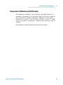
Status Indicators
Two status indicators are located on the front of the module. The lower
left indicates the power supply status, the upper right indicates the
module status.
HiVijh^cY^XVidg
\gZZc$nZaadl$gZY
A^cZedlZghl^iX]
l^i]\gZZca^\]i
Figure 19
Location of Status indicators
Power Supply Indicator
The power supply indicator is integrated into the main power switch.
When the indicator is illuminated (green) the power is ON.
56
Agilent 1260 Infinity TCC User Manual
6
Troubleshooting and Diagnostics
Status Indicators
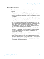
Module Status Indicator
The module status indicator indicates one of six possible module
conditions:
• When the status indicator is OFF (and power switch light is on), the
module is in a prerun condition, and is ready to begin an analysis.
• A green status indicator, indicates the module is performing an analysis
(run mode).
• A yellow indicator indicates a not- ready condition. The module is in a
not- ready state when it is waiting for a specific condition to be reached
or completed (for example, immediately after changing a set point), or
while a self- test procedure is running.
• An error condition is indicated when the status indicator is red. An
error condition indicates the module has detected an internal problem
which affects correct operation of the module. Usually, an error
condition requires attention (e.g. leak, defective internal components).
An error condition always interrupts the analysis.
If the error occurs during analysis, it is propagated within the LC
system, i.e. a red LED may indicate a problem of a different module.
Use the status display of your user interface for finding the root
cause/module of the error.
• A blinking indicator indicates that the module is in resident mode (e.g.
during update of main firmware).
• A fast blinking indicator indicates that the module is in a low- level
error mode. In such a case try to re- boot the module or try a cold- start
(see “Special Settings” on page 141. Then try a firmware update (see
“Replacing the Module’s Firmware” on page 103). If this does not help,
a main board replacement is required.
Agilent 1260 Infinity TCC User Manual
57
6
Troubleshooting and Diagnostics
Available Tests depending on User Interfaces
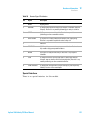
Available Tests depending on User Interfaces
NOTE
Table 5
Depending on the used interface, the available tests and the screens/reports may vary.
Preferred tool should be the Agilent Lab Advisor Software, see “Agilent Lab Advisor
Software” on page 59.
Test Functions available vs. User Interface - TCC
Test
Lab Advisor Software
Agilent ChemStation
Instant Pilot G4208A
Thermostat Function Test
Yes
Yes
No
Temperature Calibration
Yes
Yes
Yes 1
1
58
section Maintenance
Agilent 1260 Infinity TCC User Manual
Troubleshooting and Diagnostics
Agilent Lab Advisor Software
6
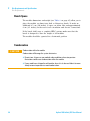
Agilent Lab Advisor Software
The Agilent Lab Advisor software is a standalone product that can be
used with or without data system. Agilent Lab Advisor software helps to
manage the lab for high quality chromatographic results and can monitor
in real time a single Agilent LC or all the Agilent GCs and LCs configured
on the lab intranet.
Agilent Lab Advisor software provides diagnostic capabilities for all
Agilent 1200 Infinity Series modules. This includes diagnostic capabilities,
calibration procedures and maintenance routines for all the maintenance
routines.
The Agilent Lab Advisor software also allows users to monitor the status
of their LC instruments. The Early Maintenance Feedback (EMF) feature
helps to carry out preventive maintenance. In addition, users can generate
a status report for each individual LC instrument. The tests and diagnostic
features as provided by the Agilent Lab Advisor software may differ from
the descriptions in this manual. For details refer to the Agilent Lab
Advisor software help files.
The Instrument Utilities is a basic version of the Lab Advisor with limited
functionality required for installation, use and maintenance. No advanced
repair, troubleshooting and monitoring functionality is included.
Agilent 1260 Infinity TCC User Manual
59
6
60
Troubleshooting and Diagnostics
Agilent Lab Advisor Software
Agilent 1260 Infinity TCC User Manual
Agilent 1260 Infinity TCC User Manual
7
Error Information
What Are Error Messages
62
General Error Messages 63
Timeout 63
Shutdown 63
Remote Timeout 64
Lost CAN Partner 65
Leak 66
Leak Sensor Open 67
Leak Sensor Short 67
Compensation Sensor Open
Compensation Sensor Short
68
68
TCC Error Messages 69
Left Fan Failed 69
Right Fan Failed 70
Open Cover 70
Cover Violation 71
Left Temperature Timeout 71
Right Temperature Timeout 72
Defective Temperature Sensor 72
Heater Profile 73
Valve Failed 74
Column Temperature 75
Heatsink Temperature 75
Defective Heater Circuit 76
This chapter describes the meaning of error messages, and provides
information on probable causes and suggested actions how to recover from
error conditions.
Agilent Technologies
61
7
Error Information
What Are Error Messages
What Are Error Messages
Error messages are displayed in the user interface when an electronic,
mechanical, or hydraulic (flow path) failure occurs which requires
attention before the analysis can be continued (for example, repair, or
exchange of consumables is necessary). In the event of such a failure, the
red status indicator at the front of the module is switched on, and an
entry is written into the module logbook.
If an error occurs outside a method run, other modules will not be
informed about this error. If it occurs within a method run, all connected
modules will get a notification, all LEDs get red and the run will be
stopped. Depending on the module type, this stop is implemented
differently. For example, for a pump the flow will be stopped for safety
reasons. For a detector, the lamp will stay on in order to avoid
equilibration time. Depending on the error type, the next run can only be
started, if the error has been resolved, for example liquid from a leak has
been dried. Errors for presumably single time events can be recovered by
switching on the system in the user interface.
Special handling is done in case of a leak. As a leak is a potential safety
issue and may have occurred at a different module from where it has been
observed, a leak always causes a shutdown of all modules, even outside a
method run.
In all cases, error propagation is done via the CAN bus or via an APG
remote cable (see documentation for the APG interface).
62
Agilent 1260 Infinity TCC User Manual
7
Error Information
General Error Messages
General Error Messages
General error messages are generic to all Agilent 1200 Infinity Series
HPLC modules.
General error messages are generic to all Agilent series HPLC modules
and may show up on other modules as well.
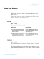
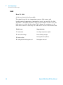
Timeout
Error ID: 0062
The timeout threshold was exceeded.
Probable cause
Suggested actions
1 The analysis was completed successfully,
Check the logbook for the occurrence and
source of a not-ready condition. Restart the
analysis where required.
and the timeout function switched off the
module as requested.
2 A not-ready condition was present during a
sequence or multiple-injection run for a
period longer than the timeout threshold.
Check the logbook for the occurrence and
source of a not-ready condition. Restart the
analysis where required.
Shutdown
Error ID: 0063
An external instrument has generated a shutdown signal on the remote
line.
The module continually monitors the remote input connectors for status
signals. A LOW signal input on pin 4 of the remote connector generates
the error message.
Agilent 1260 Infinity TCC User Manual
63
7
Error Information
General Error Messages
Probable cause
Suggested actions
1 Leak detected in another module with a
Fix the leak in the external instrument before
restarting the module.
CAN connection to the system.
2 Leak detected in an external instrument
with a remote connection to the system.
3 Shut-down in an external instrument with a
remote connection to the system.
4 The degasser failed to generate sufficient
vacuum for solvent degassing.
Fix the leak in the external instrument before
restarting the module.
Check external instruments for a shut-down
condition.
Check the vacuum degasser for an error
condition. Refer to the Service Manual for the
degasser or the 1260 pump that has the
degasser built-in.
Remote Timeout
Error ID: 0070
A not- ready condition is still present on the remote input. When an
analysis is started, the system expects all not- ready conditions (for
example, a not- ready condition during detector balance) to switch to run
conditions within one minute of starting the analysis. If a not- ready
condition is still present on the remote line after one minute the error
message is generated.
Probable cause
Suggested actions
1 Not-ready condition in one of the
Ensure the instrument showing the not-ready
condition is installed correctly, and is set up
correctly for analysis.
instruments connected to the remote line.
2 Defective remote cable.
Exchange the remote cable.
3 Defective components in the instrument
Check the instrument for defects (refer to the
instrument’s documentation).
showing the not-ready condition.
64
Agilent 1260 Infinity TCC User Manual
Error Information
General Error Messages
7
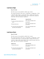
Lost CAN Partner
Error ID: 0071
During an analysis, the internal synchronization or communication
between one or more of the modules in the system has failed.
The system processors continually monitor the system configuration. If one
or more of the modules is no longer recognized as being connected to the
system, the error message is generated.
Probable cause
Suggested actions
1 CAN cable disconnected.
•
Ensure all the CAN cables are connected
correctly.
•
Ensure all CAN cables are installed
correctly.
2 Defective CAN cable.
Exchange the CAN cable.
3 Defective main board in another module.
Switch off the system. Restart the system, and
determine which module or modules are not
recognized by the system.
Agilent 1260 Infinity TCC User Manual
65
7
Error Information
General Error Messages
Leak
Error ID: 0064
A leak was detected in the module.
The signals from the two temperature sensors (leak sensor and
board- mounted temperature- compensation sensor) are used by the leak
algorithm to determine whether a leak is present. When a leak occurs, the
leak sensor is cooled by the solvent. This changes the resistance of the
leak sensor which is sensed by the leak- sensor circuit on the main board.
66
Probable cause
Suggested actions
1 Condensation.
Use a higher temperature setpoint.
2 Loose column fittings.
Ensure all fittings are tight.
3 Broken capillary.
Exchange defective capillaries.
4 Leaking column-switching valve seal.
Exchange the valve seal.
Agilent 1260 Infinity TCC User Manual
Error Information
General Error Messages
7
Leak Sensor Open
Error ID: 0083
The leak sensor in the module has failed (open circuit).
The current through the leak sensor is dependent on temperature. A leak
is detected when solvent cools the leak sensor, causing the leak- sensor
current to change within defined limits. If the current falls outside the
lower limit, the error message is generated.
Probable cause
Suggested actions
1 Leak sensor not connected to the main
Please contact your Agilent service
representative.
board.
2 Defective leak sensor.
Please contact your Agilent service
representative.
3 Leak sensor incorrectly routed, being
Please contact your Agilent service
representative.
pinched by a metal component.
Leak Sensor Short
Error ID: 0082
The leak sensor in the module has failed (short circuit).
The current through the leak sensor is dependent on temperature. A leak
is detected when solvent cools the leak sensor, causing the leak sensor
current to change within defined limits. If the current increases above the
upper limit, the error message is generated.
Probable cause
Suggested actions
1 Defective leak sensor.
Please contact your Agilent service
representative.
2 Leak sensor incorrectly routed, being
Please contact your Agilent service
representative.
pinched by a metal component.
Agilent 1260 Infinity TCC User Manual
67
7
Error Information
General Error Messages
Compensation Sensor Open
Error ID: 0081
The ambient- compensation sensor (NTC) on the main board in the module
has failed (open circuit).
The resistance across the temperature compensation sensor (NTC) on the
main board is dependent on ambient temperature. The change in
resistance is used by the leak circuit to compensate for ambient
temperature changes. If the resistance across the sensor increases above
the upper limit, the error message is generated.
Probable cause
Suggested actions
1 Defective main board.
Please contact your Agilent service
representative.
Compensation Sensor Short
Error ID: 0080
The ambient- compensation sensor (NTC) on the main board in the module
has failed (short circuit).
The resistance across the temperature compensation sensor (NTC) on the
main board is dependent on ambient temperature. The change in
resistance is used by the leak circuit to compensate for ambient
temperature changes. If the resistance across the sensor falls below the
lower limit, the error message is generated.
68
Probable cause
Suggested actions
1 Defective main board.
Please contact your Agilent service
representative.
Agilent 1260 Infinity TCC User Manual
Error Information
TCC Error Messages
7
TCC Error Messages
The following errors are TCC specific error messages.
Left Fan Failed
Error ID: 2829
The left cooling fan in the column compartment has failed.
The hall sensor on the fan shaft is used by the TCC board to monitor the
fan speed. If the fan speed falls below 2 revolutions/second for longer
than 5 s, the error message is generated.
Probable cause
Suggested actions
1 Fan cable disconnected.
Please contact your Agilent service
representative.
2 Defective fan.
Please contact your Agilent service
representative.
3 Defective TCC board.
Please contact your Agilent service
representative.
Agilent 1260 Infinity TCC User Manual
69
7
Error Information
TCC Error Messages
Right Fan Failed
Error ID: 2830
The right cooling fan in the column compartment has failed.
The hall sensor on the fan shaft is used by the TCC board to monitor the
fan speed. If the fan speed falls below 2 revolutions/second for longer
than 5 s, the error message is generated.
Probable cause
Suggested actions
1 Fan cable disconnected.
Please contact your Agilent service
representative.
2 Defective fan.
Please contact your Agilent service
representative.
3 Defective TCC board.
Please contact your Agilent service
representative.
Open Cover
Error ID:
The top foam has been removed.
The sensor on the TCC board detects when the top foam is in place. If the
foam is removed, the fans and peltier elements are switched OFF, and the
error message is generated.
Probable cause
Suggested actions
1 The top foam was removed during
Please contact your Agilent service
representative.
operation.
2 Foam not activating the sensor.
70
Please contact your Agilent service
representative.
Agilent 1260 Infinity TCC User Manual
Error Information
TCC Error Messages
7
Cover Violation
Error ID: 2833
The column compartment was switched on with the top cover and foam
open.
The sensor on the CCM board detects if the top foam is in place. If the
column compartment is switched on with the foam removed, the processor
switches OFF the peltier elements after a short delay, and the error
message is generated.
Probable cause
Suggested actions
1 The column compartment was switched on
Please contact your Agilent service
representative.
with the top cover and foam removed.
Left Temperature Timeout
Error ID: 2811
The temperature of the left heat exchanger did not reach the temperature
setpoint within the timeout threshold.
Probable cause
Suggested actions
1 Defective left heater assembly.
Please contact your Agilent service
representative.
2 Defective TCC board.
Please contact your Agilent service
representative.
Agilent 1260 Infinity TCC User Manual
71
7
Error Information
TCC Error Messages
Right Temperature Timeout
Error ID: 2812
The temperature of the right heat exchanger did not reach the
temperature setpoint within the timeout threshold.
Probable cause
Suggested actions
1 Defective right heater assembly.
Please contact your Agilent service representative.
2 Defective TCC board.
Please contact your Agilent service representative.
Defective Temperature Sensor
Error ID: 2821
One of the temperature sensors has failed.
The TCC board monitors the signal from the sensor continually. If the
signal is missing or out of range, the error message is generated.
Defective Temperature Sensor 0: left column.
Defective Temperature Sensor 1: left heat sink.
Defective Temperature Sensor 2: right column.
Defective Temperature Sensor 3: right heat sink.
Defective Temperature Sensor 4: ambient- correction sensor (located on left flex
board).
Probable cause
Suggested actions
1 Flex board not connected (only if all left or
Please contact your Agilent service representative.
right sensor error messages appear
simultaneously).
72
2 Defective heater assembly.
Please contact your Agilent service representative.
3 Defective TCC board.
Please contact your Agilent service representative.
Agilent 1260 Infinity TCC User Manual
Error Information
TCC Error Messages
7
Heater Profile
Error ID:
Heater Profile 0: left heater.
Heater Profile 2: right heater.
The temperature warm- up (or cooling) profile of the heater is incorrect.
When the temperature setpoint is changed, the heater begins heating (or
cooling) the column heat exchanger. During this time, the processor
monitors the temperature change, and checks if the temperature profile is
changing in the correct direction. If the temperature is not changing as
expected, the error message is generated.
Probable cause
Suggested actions
1 Defective heater assembly.
Please contact your Agilent service
representative.
2 Defective TCC board.
Please contact your Agilent service
representative.
Agilent 1260 Infinity TCC User Manual
73
7
Error Information
TCC Error Messages
Valve Failed
Error ID: 2825, 2826, 2827
Valve Failed 0: failed to switch to the position where ports 1 and 2 are
connected.
Valve Failed 1: failed to switch to the position where ports 1 and 6 are
connected.
The column- switching valve failed to switch.
The switching of the column- switching valve is monitored by two micro
switches on the valve assembly. The switches detect the successful
completion of the valve movement within a predefined time window. If the
valve fails to reach the end point, or fails to reach the end point within
the time window, the error message is generated.
74
Probable cause
Suggested actions
1 Defective column-switching valve.
Please contact your Agilent service
representative.
2 Defective TCC board.
Please contact your Agilent service
representative.
Agilent 1260 Infinity TCC User Manual
Error Information
TCC Error Messages
7
Column Temperature
Error ID: 2836
The temperature of the column heat exchanger has exceeded the maximum
limit.
Column Temperature 0: left heater.
Column Temperature 2: right heater.
For safety reasons, the maximum column heat- exchanger temperature is
105 °C. If an electronic failure occurs which causes the heater to heat
continually, the current is switched off when the temperature exceeds
105 °C, and the error message is generated.
Probable cause
Suggested actions
1 Defective heater assembly.
Please contact your Agilent service representative.
2 Defective TCC board.
Please contact your Agilent service representative.
Heatsink Temperature
Error ID: 2837
The temperature of the Peltier heatsink has exceeded the maximum limit.
Heatsink Temperature 0: left heater.
Heatsink Temperature 2: right heater
The maximum temperature of the Peltier heatsink is 70 °C. If an
electronic failure occurs which causes the heatsink to reach 70 °C, the
current is switched OFF and the error message is generated.
Probable cause
Suggested actions
1 Defective heater assembly.
Please contact your Agilent service representative.
2 Defective TCC board.
Please contact your Agilent service representative.
Agilent 1260 Infinity TCC User Manual
75
7
Error Information
TCC Error Messages
Defective Heater Circuit
Error ID: 2860
The electronic circuit for control of the heater assemblies is defective.
The processor checks the function of the heater circuits continually. If a
defect is detected in the control circuit, the processor switches OFF the
heater (peltier) assemblies, and the error message is generated.
76
Probable cause
Suggested actions
1 Defective TCC board.
Please contact your Agilent service
representative.
Agilent 1260 Infinity TCC User Manual
Agilent 1260 Infinity TCC User Manual
8
Test Functions
Thermostat Function Test 78
Evaluating the Thermostat Function Test
Pressure Test
80
81
Column Thermostat Temperature Calibration 82
Temperature Calibration Procedure 83
Temperature Calibration with Agilent Lab Advisor
Column Thermostat Calibration Problems 89
Installing the Temperature Sensor 90
83
This chapter describes the TCC’s built in test functions.
Agilent Technologies
77
8
Test Functions
Thermostat Function Test
Thermostat Function Test
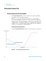
Thermostat Function Test Description
The Thermostat Function Test is used to evaluate the cooling and heating
performance of the two peltier elements.
When the test is started, both heat exchangers are cooled initially to
25 °C. This temperature is held for 12 seconds, and then the setpoint is
changed to 20 °C. The time required to reach 20 °C is a measure of the
cooling efficiency of the peltier elements. At 3.5 minutes, the setpoint is
changed to 30 °C, and both elements begin heating. The time required to
reach 30 °C is a measure of heating efficiency.
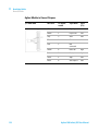
Thermostat Function Test Result
A typical Thermostat Function Test profile is shown in Figure 20 on page 78.
IZbeZgVijgZP8R
G^\]iEZai^ZgZaZbZci
AZ[iEZai^ZgZaZbZci
I^bZPb^cjiZhR
Figure 20
78
Typical Thermostat Function Test Profile
Agilent 1260 Infinity TCC User Manual
Test Functions
Thermostat Function Test
8
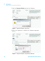
Thermostat Test with Agilent LabAdvisor
1 1. Select the Thermostat Test and start the test.
Figure 21
Thermostat Test
Agilent 1260 Infinity TCC User Manual
79
8
Test Functions
Thermostat Function Test
Evaluating the Thermostat Function Test
During the cooling phase, the Peltier elements should cool at a rate of
>2 °C/minute. During the heating phase, the temperature change should be
>3 °C/minute. Defective thermostat components may cause cooling or
heating rates to fall outside these limits.
Thermostat Function Test Failed
Probable cause
Suggested actions
1 Column compartment cover not installed
Ensure cover is installed correctly.
correctly (bad insulation).
2 Air intake blocked (insufficient air flow for
cooling).
3 Poor peltier efficiency (if setpoint
Ensure sufficient space is available for air
circulation see “Bench Space” on page 24.
Exchange the heater assembly.
temperatures can still be reached, and are
stable, there is no requirement to exchange
the heater assembly).
80
4 Defective sensors on flex board.
Exchange the heater assembly.
5 Defective heater assembly.
Exchange the heater assembly.
Agilent 1260 Infinity TCC User Manual
8
Test Functions
Pressure Test
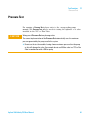
Pressure Test
For running a Pressure Test, please refer to the corresponding pump
manual. The Pressure Test may be used for testing the tightness of a valve
installed in the TCC or Flex Cube.
CAUTION
Wrong use of Pressure Test may damage valve.
The current implementation of the Pressure Test automatically uses the maximum
pressure generated by the pump used in the system.
➔ Do not use the test for modules having a lower maximum pressure than the pump
as this will damage the valve. For example do not use 400 bar valve in a TCC or Flex
Cube in combination with a 600 bar pump.
Agilent 1260 Infinity TCC User Manual
81
8
Test Functions
Column Thermostat Temperature Calibration
Column Thermostat Temperature Calibration
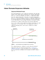
Temperature Calibration Principle
The actual temperatures of the column heat exchangers (left and right)
depend on the column setpoint temperature. For setpoint temperatures
above 36 °C, the heat exchangers are heated to a temperature slightly
above the setpoint temperature. Conversely, for setpoint temperatures
below 36 °C, the heat exchangers are kept at a temperature slightly below
the setpoint temperature. This fine temperature correction compensates
for the small amount of heat exchange through the instrument housing,
and ensures the column is always kept at the setpoint temperature.
At 36 °C, the column setpoint and heat- exchanger temperatures are equal
(temperature cross- over point). This is the temperature at which a
calibrated measuring device can be used to calibrate the column
thermostat.
IZbeZgVijgZ
Y^[[ZgZcXZP8R
iZbeZgVijgZVi
bZVhjg^c\ed^ci
8dajbchZied^ciiZbeZgVijgZ
8Va^WgVi^dcViXgdhh"dkZged^ci(+8
IZbeZgVijgZP8R
Figure 22
1-Point Calibration at the Temperature Cross-Over Point
The column thermostat is calibrated correctly when the measured
temperature (using the external measuring device, “Temperature
Calibration Procedure” on page 83) and the cross- over temperature
(36 °C) of both heat exchangers (left and right) are within a range of
± 0.5 °C.
82
Agilent 1260 Infinity TCC User Manual
8
Test Functions
Column Thermostat Temperature Calibration
Temperature Calibration Procedure
Tools required
Description
Temperature measuring device
(see note below)
Parts required
#
Description
1
Calibrated temperature measuring device
NOTE
For the measuring and calibration process Agilent Technologies recommends a
thermometer with 0.1 °C precision. Contact the local Agilent Technologies support
representative for ordering information.
NOTE
The figures in this procedure refer to a specific type of temperature sensor (Heraeus
Quat340, quartz surface-temperature measurement sensor). Other sensors may require a
different fixing.
1 Install the temperature sensor, see “Installing the Temperature
Sensor” on page 90.
Temperature Calibration with Agilent Lab Advisor
One Point Temperature Calibration with Agilent Lab Advisor
This is the standard 1- point calibration. If a 2- point calibration is
required, refer to “Two Point Temperature Calibration with Agilent Lab
Advisor” on page 86
If only one sensor is available, the procedure has to be performed for
both, the left and right heat exchanger separately.
Agilent 1260 Infinity TCC User Manual
83
8
Test Functions
Column Thermostat Temperature Calibration
1 Select the Temperature Calibration and start the calibration.
Figure 23
Temperature Calibration - Step 1 (Start)
2 Wait for the temperature to stabilize at the calibration temperature
(36 °C).
Figure 24
84
Temperature Calibration - Step 2 (Wait for stabilization)
Agilent 1260 Infinity TCC User Manual
8
Test Functions
Column Thermostat Temperature Calibration
3 Measure the temperature of the heat exchanger.
Figure 25
Temperature Calibration - Step 3 (Save new calibration values)
4 If the measured temperature deviates by more than ± 0.5 °C from the
actual temperature, enter the measured value in the
measured- temperature field for the left and/or right heat exchanger.
Figure 26
OnePoint Calibration - Step 4 (Calibration done)
5 Repeat the calibration procedure for the right heat exchanger.
Agilent 1260 Infinity TCC User Manual
85
8
Test Functions
Column Thermostat Temperature Calibration
NOTE
Limits
After calibration, the measured temperature and the calibration temperature should be
within ± 0.5 °C. The maximum deviation which can be adjusted ± 1.6 °C. If the measured
value and the calibration value differ by more than ± 1.6 °C, this is an indication that a
problem exists, see “Column Thermostat Calibration Problems” on page 89
Two Point Temperature Calibration with Agilent Lab Advisor
In addition to the standard 1- point calibration, the 2- point calibration
uses a second temperature point (both temperatures can be entered
individually).
With this calibration it is possible to get the measured temperature in the
column closer to the set temperature when working at higher temperature,
e.g. above 60 degree (if required).
The 2- point temperature calibration will overlay on an existing 1- point
calibration. The instrument will not know the 1- point temperature
calibration anymore. The information stays in a specific memory area that
is not overwritten by firmware updates.
In case the instrument must be converted back to standard 1- point
calibration, a special command has to used, see “Turning off the 2- point
calibration” on page 88.
The figures below show the calibration process with the Agilent
LabAdvisor software. It is similar to the 1- Point Calibration.
86
Agilent 1260 Infinity TCC User Manual
Test Functions
Column Thermostat Temperature Calibration
Figure 27
Two Point Calibration – Start
Figure 28
Two Point Calibration – Define the two temperatures
Agilent 1260 Infinity TCC User Manual
8
87
8
Test Functions
Column Thermostat Temperature Calibration
Figure 29
Two Point Calibration – Done
Turning off the 2-point calibration
Use the command line in the "Module Service Center" of the Agilent
LabAdvisor software.
1 For left heat exchanger use the command
E2PC 0,0 and Execute.
The user interface will reply with RA 0000 E2PC 0,0 if command was
entered correctly.
2 For right heat exchanger use the command
E2PC 1,0 and Execute.
The user interface will reply with RA 0000 E2PC 1,0 if command was
entered correctly.
3 Perform the “Temperature Calibration” on page xx.
88
Agilent 1260 Infinity TCC User Manual
Test Functions
Column Thermostat Temperature Calibration
8
Column Thermostat Calibration Problems
If the temperature cannot be calibrated, check the following:
• Has the thermostat front cover been closed correctly?
• Is the measuring device functioning correctly, and is calibrated
according to the manufacturers instructions?
Hardware Failures
Probable hardware failures that can lead to a failed calibration procedure
are:
• Defective or wrongly calibrated measuring device.
• Defective heater assembly.
• Defective ambient- temperature sensor.
• Defective CCM board.
Agilent 1260 Infinity TCC User Manual
89
8
Test Functions
Column Thermostat Temperature Calibration
Installing the Temperature Sensor
Installation of the temperature sensor is required for the temperature
calibration and temperature verification procedures.
NOTE
The figures below refer to a specific type of temperature sensor (Heraeus, Quat340, quartz
surface-temperature measurement sensor). Other sensors may require a different fixing.
1 Remove the front cover.
2 Install the temperature sensor at the measurement
position on the left heat exchanger.
3 Route the sensor wire through the slit in the leak tray.
90
4 Re-install the front cover.
Agilent 1260 Infinity TCC User Manual
Agilent 1260 Infinity TCC User Manual
9
Maintenance
Warnings and Cautions
92
Introduction to Maintenance
Overview of Maintenance
Cleaning the Module
94
95
96
Changing Column Identification Tags
97
Replacing Head Parts of Column Switching Valve
Correcting Leaks
99
102
Replacing the Module’s Firmware
103
This chapter describes the maintenance and repair of the TCC.
Agilent Technologies
91
9
Maintenance
Warnings and Cautions
Warnings and Cautions
WA R N I N G
Personal injury or damage to the product
Agilent is not responsible for any damages caused, in whole or in part, by improper
use of the products, unauthorized alterations, adjustments or modifications to the
products, failure to comply with procedures in Agilent product user guides, or use of
the products in violation of applicable laws, rules or regulations.
➔ Use your Agilent products only in the manner described in the Agilent product user
guides.
WA R N I N G
Module is partially energized when switched off, as long as the power cord is
plugged in.
Risk of stroke and other personal injury. Repair work at the module can lead to
personal injuries, e. g. shock hazard, when the module cover is opened and the
instrument is connected to power.
➔ Never perform any adjustment, maintenance or repair of the module with the top
cover removed and with the power cord plugged in.
➔ The security lever at the power input socket prevents that the module cover is taken
off when line power is still connected. Never plug the power line back in when cover
is removed.
WA R N I N G
Sharp metal edges
Sharp-edged parts of the equipment may cause injuries.
➔ To prevent personal injury, be careful when getting in contact with sharp metal
areas.
92
Agilent 1260 Infinity TCC User Manual
9
Maintenance
Warnings and Cautions
WA R N I N G
Toxic, flammable and hazardous solvents, samples and reagents
The handling of solvents, samples and reagents can hold health and safety risks.
➔ When working with these substances observe appropriate safety procedures (for
example by wearing goggles, safety gloves and protective clothing) as described in
the material handling and safety data sheet supplied by the vendor, and follow good
laboratory practice.
➔ The volume of substances should be reduced to the minimum required for the
analysis.
➔ Do not operate the instrument in an explosive atmosphere.
CAUTION
Electronic boards and components are sensitive to electrostatic discharge (ESD).
ESD can damage electronic boards and components.
➔ Be sure to hold the board by the edges, and do not touch the electrical components.
Always use ESD protection (for example, an ESD wrist strap) when handling
electronic boards and components.
CAUTION
Hot heat exchangers
The column compartment has two heat exchanger assemblies that might be hot.
➔ Allow them to cool down before starting repairs.
CAUTION
Safety standards for external equipment
➔ If you connect external equipment to the instrument, make sure that you only use
accessory units tested and approved according to the safety standards appropriate
for the type of external equipment.
Agilent 1260 Infinity TCC User Manual
93
9
Maintenance
Introduction to Maintenance
Introduction to Maintenance
The main user accessible assemblies of the Agilent 1260 Infinity
Thermostatted Column Compartment can be accessed from the front
(simple repairs) and don't require to remove the TCC from the system
stack.
94
Agilent 1260 Infinity TCC User Manual
Maintenance
Overview of Maintenance
9
Overview of Maintenance
The following pages describe maintenance procedures (simple repairs) that
can be done without opening the main cover.
Table 6
Simple Repairs
Procedure
Typical Frequency
“Cleaning the Module” on
page 96
If required
“Changing Column Identification
Tags” on page 97
When column performance or new
application requires a change
“Replacing Head Parts of Column
Switching Valve” on page 99
If the valve performance shows
indication of leakage or wear
“Correcting Leaks” on page 102
If a leak has occurred
Agilent 1260 Infinity TCC User Manual
Notes
Check for leaks
95
9
Maintenance
Cleaning the Module
Cleaning the Module
To keep the module case clean, use a soft cloth slightly dampened with
water, or a solution of water and mild detergent.
WA R N I N G
Liquid dripping into the electronic compartment of your module can cause shock
hazard and damage the module
➔ Do not use an excessively damp cloth during cleaning.
➔ Drain all solvent lines before opening any connections in the flow path.
96
Agilent 1260 Infinity TCC User Manual
Maintenance
Changing Column Identification Tags
9
Changing Column Identification Tags
The column compartment is equipped with a column- identification system,
that stores column specific information. Two identification antennas are
incorporated in the heat exchanger assemblies.
6ciZccVh
8dajbc"^YZci^[^XVi^dciV\
8dajbcXa^e
Figure 30
Column-Identification System
When
If column is used on the opposite heat exchanger or a tag is added to a new column.
Parts required
#
p/n
Description
1
5062-8588
Column identification tag (1x), re-order (3/pk)
1 The identification tag can be easily removed from the column.
2 The tag needs to be placed differently, depending on whether the
column is installed at the left or right heat exchanger, see Figure 31 on
page 98 and Figure 32 on page 98. The Agilent logo should always be
at front.
When correctly placed on the heat exchanger, the distance between tag
and tag reader is 1 – 2 mm. This is the optimum distance for proper
function.
Agilent 1260 Infinity TCC User Manual
97
9
Maintenance
Changing Column Identification Tags
8dajbc"^YZci^[^XVi^dciV\
Figure 31
Column-Identification Tag for Left Heat Exchanger
Figure 32
Column-Identification Tag for Right Heat Exchanger
8dajbc"^YZci^[^XVi^dciV\
3 For columns with small diameter, a cable tie wrap should be used to fix
the column identification tag to the column. Assure that the tie wrap
does not block the front cover.
98
Agilent 1260 Infinity TCC User Manual
Maintenance
Replacing Head Parts of Column Switching Valve
9
Replacing Head Parts of Column Switching Valve
>hdaVi^dchZVa
GdidghZVa
HiVidgg^c\
HiVidg]ZVY
Heg^c\h^YZh]dlhidgZVg
HiVidghXgZlh
Figure 33
When
Tools required
Column Switching Valve Parts
If valve leaks.
Description
Wrench, 1/4 inch (supplied in HPLC Tool-Kit)
Hexagonal key, 9/64 inch (supplied in HPLC Tool-Kit)
Agilent 1260 Infinity TCC User Manual
99
9
Maintenance
Replacing Head Parts of Column Switching Valve
1 Remove capillaries from ports.
2 Loosen each fixing stator screw two turns at a time. Remove bolts from
head.
3 Remove the stator head (and stator face if applicable).
4 Remove the stator ring.
5 Remove the rotor seal (and isolation seal if damaged or contaminated).
6 Install the new isolation seal (if required). Ensure the metal spring
inside the ring faces towards the valve body.
7 Install the new rotor seal.
8 Replace the stator ring. Ensure the stator ring is flush with the valve
body.
9 Place the new (if required) stator face in place on the stator head.
Reinstall the stator head.
10 Insert the stator screws in the stator head. Tighten the screws
alternately two turns at a time until the stator head is secure.
100
Agilent 1260 Infinity TCC User Manual
9
Maintenance
Replacing Head Parts of Column Switching Valve
11 Reconnect the pump capillaries to the valve ports. Slide the waste tube
into the waste holder in the leak tray.
CAUTION
Wrong use of Pressure Test may damage valve.
The current implementation of the Pressure Test automatically uses the maximum
pressure generated by the pump used in the system.
➔ Do not use the test for modules having a lower maximum pressure than the pump
as this will damage the valve. For example do not use 400 bar valve in a TCC or Flex
Cube in combination with a 600 bar pump.
12 Perform a Pressure Test to ensure the valve is pressure tight.
Agilent 1260 Infinity TCC User Manual
101
9
Maintenance
Correcting Leaks
Correcting Leaks
When
If a leakage has occurred at the heat exchanger or at the capillary connections or at the column
switching valve.
Tools required
Description
Tissue
Pipette
Wrench, 1/4 – 5/16 inch
(for capillary connections)
NOTE
Depending on the column position or the use of additional heat-exchanger assemblies, the
view of Figure 34 on page 102 may vary.
1 Remove the front cover.
2 Use a pipette and tissue to dry the leak sensor area.
3 Observe the capillary connections and the column switching valve for
leaks and correct, if required.
4 Re- install the front cover.
8dajbchl^iX]^c\kVakZ
8dajbc
AZV`hZchdgVhhZbWan
LVhiZ djiaZi
Figure 34
102
Possible Leak Areas
Agilent 1260 Infinity TCC User Manual
9
Maintenance
Replacing the Module’s Firmware
Replacing the Module’s Firmware
When
The installation of newer firmware might be necessary
• if a newer version solves problems of older versions or
• to keep all systems on the same (validated) revision.
The installation of older firmware might be necessary
• to keep all systems on the same (validated) revision or
• if a new module with newer firmware is added to a system or
• if third party control software requires a special version.
Tools required
Description
LAN/RS-232 Firmware Update Tool
OR
Agilent Lab Advisor software
OR
Instant Pilot G4208A
(only if supported by module)
Parts required
Preparations
#
Description
1
Firmware, tools and documentation from Agilent web site
Read update documentation provided with the Firmware Update Tool.
To upgrade/downgrade the module’s firmware carry out the following
steps:
1 Download the required module firmware, the latest LAN/RS- 232 FW
Update Tool and the documentation from the Agilent web.
• http://www.chem.agilent.com/_layouts/agilent/downloadFirmware.aspx?
whid=69761
2 For loading the firmware into the module follow the instructions in the
documentation.
Agilent 1260 Infinity TCC User Manual
103
9
Maintenance
Replacing the Module’s Firmware
Module Specific Information
Table 7
Module Specific Information (G1316A/B)
G1316A
104
Initial firmware (main and resident)
Depends on main board revision. Newer
versions (G1316-66530 and higher) allow
A.05.05 and above only.
Compatibility with 1100 / 1200 series modules
always
Conversion to / emulation
N/A
Agilent 1260 Infinity TCC User Manual
Agilent 1260 Infinity TCC User Manual
10
Parts for Maintenance
Column Switching Valve 2 Position/6 Port
106
Kits 107
Accessory Kit 107
Spring Kit 107
Plastic Parts
Leak Parts
108
109
This chapter provides information on parts for maintenance.
Agilent Technologies
105
10 Parts for Maintenance
Column Switching Valve 2 Position/6 Port
Column Switching Valve 2 Position/6 Port
Item
p/n
Description
G1353-68750
Valve Kit 2POS/6PORT 600 bar
G1316-68708
Capillary Kit Column Switching includes two capillaries (0.17 mm i.d.,
180 mm) and three capillaries (0.17 mm i.d., 90 mm)
1
5068-0018
Stator screws
2
0101-1417
Stator head
3
5068-0118
Stator ring
4
0101-1409
Rotor Seal
5
1535-4045
Bearing ring
*
)
(
'
Heg^c\h^YZh]dlhidgZVg
&
Figure 35
106
Column Switching Valve Parts
Agilent 1260 Infinity TCC User Manual
Parts for Maintenance
Kits
10
Kits
Accessory Kit
The Accessory kit (G1316- 68755) contains some specific accessories and
tools needed for the installation of the TCC.
p/n
Description
5063-6527
Tubing assembly, i.d. 6 mm, o.d. 9 mm, 1.2 m (to waste)
5063-6526 (2x)
Column clamp (for re-order 6/pk)
G1316-87300
Capillary ST 0.17 x 90 mm S/S
5181-1516
CAN cable, Agilent module to module, 0.5 m
Spring Kit
p/n
Description
G1316-68733
Spring kit for G1316A (1100 Series)
G1316-68734
Spring kit for G1316A/B (1200 Series)
Agilent 1260 Infinity TCC User Manual
107
10 Parts for Maintenance
Plastic Parts
Plastic Parts
Item
p/n
Description
1
G1316-68714
Front Cover C (NEW)
G1316-68734
Spring kit for Front Cover (NEW)
5043-0207
Name plate 1260
2
'
&
Figure 36
108
Plastic Parts
Agilent 1260 Infinity TCC User Manual
Parts for Maintenance
Leak Parts
10
Leak Parts
Item
p/n
Description
1
G1316-67000
Leak tube kit
includes following items: Funnel holder G1316C, tubing-flex
polyethylene, leak funnel
2
G1316-42303
Capillary guide
&
'
Figure 37
Leak Parts
Agilent 1260 Infinity TCC User Manual
109
10 Parts for Maintenance
Leak Parts
110
Agilent 1260 Infinity TCC User Manual
Agilent 1260 Infinity TCC User Manual
11
Identifying Cables
Cable Overview
112
Analog Cables
114
Remote Cables
116
BCD Cables
119
CAN/LAN Cables
121
External Contact Cable
Agilent Module to PC
122
123
Agilent 1200 Module to Printer
124
This chapter provides information on cables used with the 1260 Infinity series
of HPLC modules.
Agilent Technologies
111
11 Identifying Cables
Cable Overview
Cable Overview
NOTE
Never use cables other than the ones supplied by Agilent Technologies to ensure proper
functionality and compliance with safety or EMC regulations.
Analog cables
p/n
Description
35900-60750
Agilent module to 3394/6 integrators
35900-60750
Agilent 35900A A/D converter
01046-60105
Analog cable (BNC to general purpose, spade lugs)
Remote cables
p/n
Description
03394-60600
Agilent module to 3396A Series I integrators
3396 Series II / 3395A integrator, see details in section “Remote Cables” on
page 116
03396-61010
Agilent module to 3396 Series III / 3395B integrators
5061-3378
Remote Cable
01046-60201
Agilent module to general purpose
BCD cables
112
p/n
Description
03396-60560
Agilent module to 3396 integrators
G1351-81600
Agilent module to general purpose
Agilent 1260 Infinity TCC User Manual
11
Identifying Cables
Cable Overview
CAN cables
p/n
Description
5181-1516
CAN cable, Agilent module to module, 0.5 m
5181-1519
CAN cable, Agilent module to module, 1 m
LAN cables
p/n
Description
5023-0203
Cross-over network cable, shielded, 3 m (for point to point connection)
5023-0202
Twisted pair network cable, shielded, 7 m (for point to point connection)
External Contact Cable
p/n
Description
G1103-61611
External contact cable - Agilent module interface board to general purposes
RS-232 cables
p/n
Description
G1530-60600
RS-232 cable, 2 m
RS232-61601
RS-232 cable, 2.5 m
Instrument to PC, 9-to-9 pin (female). This cable has special pin-out, and is
not compatible with connecting printers and plotters. It's also called "Null
Modem Cable" with full handshaking where the wiring is made between pins
1-1, 2-3, 3-2, 4-6, 5-5, 6-4, 7-8, 8-7, 9-9.
5181-1561
RS-232 cable, 8 m
Agilent 1260 Infinity TCC User Manual
113
11 Identifying Cables
Analog Cables
Analog Cables
One end of these cables provides a BNC connector to be connected to
Agilent modules. The other end depends on the instrument to which
connection is being made.
Agilent Module to 3394/6 Integrators
p/n 35900-60750
Pin 3394/6
Pin Agilent
module
1
114
Signal Name
Not connected
2
Shield
Analog -
3
Center
Analog +
Agilent 1260 Infinity TCC User Manual
Identifying Cables
Analog Cables
11
Agilent Module to BNC Connector
p/n 8120-1840
Pin BNC
Pin Agilent
module
Signal Name
Shield
Shield
Analog -
Center
Center
Analog +
Pin Agilent
module
Signal Name
Agilent Module to General Purpose
p/n 01046-60105
Pin
1
Agilent 1260 Infinity TCC User Manual
Not connected
2
Black
Analog -
3
Red
Analog +
115
11 Identifying Cables
Remote Cables
Remote Cables
One end of these cables provides a Agilent Technologies APG (Analytical
Products Group) remote connector to be connected to Agilent modules.
The other end depends on the instrument to be connected to.
Agilent Module to 3396A Integrators
p/n 03394-60600
Pin 3396A
Pin Agilent
module
Signal Name
9
1 - White
Digital ground
NC
2 - Brown
Prepare run
Low
3
3 - Gray
Start
Low
NC
4 - Blue
Shut down
Low
NC
5 - Pink
Not
connected
NC
6 - Yellow
Power on
High
5,14
7 - Red
Ready
High
1
8 - Green
Stop
Low
NC
9 - Black
Start request
Low
13, 15
Active
(TTL)
Not
connected
Agilent Module to 3396 Series II / 3395A Integrators
Use the cable Agilent module to 3396A Series I integrators (03394- 60600)
and cut pin #5 on the integrator side. Otherwise the integrator prints
START; not ready.
116
Agilent 1260 Infinity TCC User Manual
Identifying Cables
Remote Cables
11
Agilent Module to 3396 Series III / 3395B Integrators
p/n 03396-61010
Pin 33XX
Pin Agilent
module
Signal Name
9
1 - White
Digital ground
NC
2 - Brown
Prepare run
Low
3
3 - Gray
Start
Low
NC
4 - Blue
Shut down
Low
NC
5 - Pink
Not connected
NC
6 - Yellow
Power on
High
14
7 - Red
Ready
High
4
8 - Green
Stop
Low
NC
9 - Black
Start request
Low
13, 15
Active
(TTL)
Not connected
Agilent Module to Agilent 35900 A/D Converters
p/n 5061-3378
Agilent 1260 Infinity TCC User Manual
Pin 35900 A/D Pin Agilent
module
Signal Name
Active
(TTL)
1 - White
1 - White
Digital ground
2 - Brown
2 - Brown
Prepare run
Low
3 - Gray
3 - Gray
Start
Low
4 - Blue
4 - Blue
Shut down
Low
5 - Pink
5 - Pink
Not connected
6 - Yellow
6 - Yellow
Power on
High
7 - Red
7 - Red
Ready
High
8 - Green
8 - Green
Stop
Low
9 - Black
9 - Black
Start request
Low
117
11 Identifying Cables
Remote Cables
Agilent Module to General Purpose
p/n 01046-60201
118
Wire Color
Pin Agilent
module
Signal Name
Active
(TTL)
White
1
Digital ground
Brown
2
Prepare run
Low
Gray
3
Start
Low
Blue
4
Shut down
Low
Pink
5
Not
connected
Yellow
6
Power on
High
Red
7
Ready
High
Green
8
Stop
Low
Black
9
Start request
Low
Agilent 1260 Infinity TCC User Manual
Identifying Cables
BCD Cables
11
BCD Cables
One end of these cables provides a 15- pin BCD connector to be connected
to the Agilent modules. The other end depends on the instrument to be
connected to
Agilent Module to General Purpose
p/n G1351-81600
Agilent 1260 Infinity TCC User Manual
Wire Color
Pin Agilent
module
Signal Name
BCD Digit
Green
1
BCD 5
20
Violet
2
BCD 7
80
Blue
3
BCD 6
40
Yellow
4
BCD 4
10
Black
5
BCD 0
1
Orange
6
BCD 3
8
Red
7
BCD 2
4
Brown
8
BCD 1
2
Gray
9
Digital ground
Gray
Gray/pink
10
BCD 11
800
Red/blue
11
BCD 10
400
White/green
12
BCD 9
200
Brown/green
13
BCD 8
100
not connected
14
not connected
15
+5V
Low
119
11 Identifying Cables
BCD Cables
Agilent Module to 3396 Integrators
p/n 03396-60560
120
Pin 3396
Pin Agilent
module
Signal Name
BCD Digit
1
1
BCD 5
20
2
2
BCD 7
80
3
3
BCD 6
40
4
4
BCD 4
10
5
5
BCD0
1
6
6
BCD 3
8
7
7
BCD 2
4
8
8
BCD 1
2
9
9
Digital ground
NC
15
+5V
Low
Agilent 1260 Infinity TCC User Manual
Identifying Cables
CAN/LAN Cables
11
CAN/LAN Cables
Both ends of this cable provide a modular plug to be connected to
Agilent modules CAN or LAN connectors.
CAN Cables
p/n
Description
5181-1516
CAN cable, Agilent module to module, 0.5 m
5181-1519
CAN cable, Agilent module to module, 1 m
LAN Cables
p/n
Description
5023-0203
Cross-over network cable, shielded, 3 m (for point to point connection)
5023-0202
Twisted pair network cable, shielded, 7 m (for point to point connection)
Agilent 1260 Infinity TCC User Manual
121
11 Identifying Cables
External Contact Cable
External Contact Cable
5
10
15
1
6
11
One end of this cable provides a 15- pin plug to be connected to
Agilent modules interface board. The other end is for general purpose.
Agilent Module Interface Board to general purposes
p/n G1103-61611
122
Color
Pin Agilent
module
Signal Name
White
1
EXT 1
Brown
2
EXT 1
Green
3
EXT 2
Yellow
4
EXT 2
Grey
5
EXT 3
Pink
6
EXT 3
Blue
7
EXT 4
Red
8
EXT 4
Black
9
Not connected
Violet
10
Not connected
Grey/pink
11
Not connected
Red/blue
12
Not connected
White/green
13
Not connected
Brown/green
14
Not connected
White/yellow
15
Not connected
Agilent 1260 Infinity TCC User Manual
11
Identifying Cables
Agilent Module to PC
Agilent Module to PC
p/n
Description
G1530-60600
RS-232 cable, 2 m
RS232-61601
RS-232 cable, 2.5 m
Instrument to PC, 9-to-9 pin (female). This cable has special pin-out, and is
not compatible with connecting printers and plotters. It's also called "Null
Modem Cable" with full handshaking where the wiring is made between pins
1-1, 2-3, 3-2, 4-6, 5-5, 6-4, 7-8, 8-7, 9-9.
5181-1561
RS-232 cable, 8 m
Agilent 1260 Infinity TCC User Manual
123
11 Identifying Cables
Agilent 1200 Module to Printer
Agilent 1200 Module to Printer
124
p/n
Description
5181-1529
Cable Printer Serial & Parallel, is a SUB-D 9 pin female vs. Centronics
connector on the other end (NOT FOR FW UPDATE). For use with G1323
Control Module.
Agilent 1260 Infinity TCC User Manual
Agilent 1260 Infinity TCC User Manual
12
Hardware Information
Firmware Description
126
Electrical Connections 129
Serial Number Information 1260 Infinity
Electrical Connections 129
Interfaces 131
Overview Interfaces
130
134
Setting the 8-bit Configuration Switch (without On-Board LAN)
Communication Settings for RS-232C 139
Special Settings 141
Instrument Layout
138
142
This chapter describes the detector in more detail on hardware and electronics.
Agilent Technologies
125
12 Hardware Information
Firmware Description
Firmware Description
The firmware of the instrument consists of two independent sections:
• a non- instrument specific section, called resident system
• an instrument specific section, called main system
Resident System
This resident section of the firmware is identical for all Agilent
1100/1200/1220/1260/1290 series modules. Its properties are:
• the complete communication capabilities (CAN, LAN and RS- 232C)
• memory management
• ability to update the firmware of the 'main system'
Main System
Its properties are:
• the complete communication capabilities (CAN, LAN and RS- 232C)
• memory management
• ability to update the firmware of the 'resident system'
In addition the main system comprises the instrument functions that are
divided into common functions like
• run synchronization through APG remote,
• error handling,
• diagnostic functions,
• or module specific functions like
• internal events such as lamp control, filter movements,
• raw data collection and conversion to absorbance.
Firmware Updates
Firmware updates can be done using your user interface:
• PC and Firmware Update Tool with local files on the hard disk
126
Agilent 1260 Infinity TCC User Manual
Hardware Information
Firmware Description
12
• Instant Pilot (G4208A) with files from a USB Flash Disk
• Agilent Lab Advisor software B.01.03 and above
The file naming conventions are:
PPPP_RVVV_XXX.dlb, where
PPPP is the product number, for example, 1315AB for the G1315A/B DAD,
R the firmware revision, for example, A for G1315B or B for the G1315C
DAD,
VVV is the revision number, for example 102 is revision 1.02,
XXX is the build number of the firmware.
For instructions on firmware updates refer to section Replacing Firmware
in chapter "Maintenance" or use the documentation provided with the
Firmware Update Tools.
NOTE
Update of main system can be done in the resident system only. Update of the resident
system can be done in the main system only.
Main and resident firmware must be from the same set.
BV^c;LjeYViZ
BV^cHnhiZb
GZh^YZciHnhiZb
GZh^YZci;LJeYViZ
Figure 38
Firmware Update Mechanism
Agilent 1260 Infinity TCC User Manual
127
12 Hardware Information
Firmware Description
NOTE
Some modules are limited in downgrading due to their main board version or their initial
firmware revision. For example, a G1315C DAD SL cannot be downgraded below firmware
revision B.01.02 or to a A.xx.xx.
Some modules can be re-branded (e.g. G1314C to G1314B) to allow operation in specific
control software environments. In this case the feature set of the target type are use and
the feature set of the original are lost. After re-branding (e.g. from G1314B to G1314C), the
original feature set is available again.
All these specific informations are described in the documentation provided with the
firmware update tools.
The firmware update tools, firmware and documentation are available
from the Agilent web.
• http://www.chem.agilent.com/_layouts/agilent/downloadFirmware.aspx?whid=69761
128
Agilent 1260 Infinity TCC User Manual
12
Hardware Information
Electrical Connections
Electrical Connections
• The CAN bus is a serial bus with high speed data transfer. The two
connectors for the CAN bus are used for internal module data transfer
and synchronization.
• One analog output provides signals for integrators or data handling
systems.
• The REMOTE connector may be used in combination with other
analytical instruments from Agilent Technologies if you want to use
features such as start, stop, common shut down, prepare, and so on.
• With the appropriate software, the RS- 232C connector may be used to
control the module from a computer through a RS- 232C connection.
This connector is activated and can be configured with the
configuration switch.
• The power input socket accepts a line voltage of 100 – 240 VAC ± 10 %
with a line frequency of 50 or 60 Hz. Maximum power consumption
varies by module. There is no voltage selector on your module because
the power supply has wide- ranging capability. There are no externally
accessible fuses, because automatic electronic fuses are implemented in
the power supply.
NOTE
Never use cables other than the ones supplied by Agilent Technologies to ensure proper
functionality and compliance with safety or EMC regulations.
Agilent 1260 Infinity TCC User Manual
129
12 Hardware Information
Electrical Connections
Serial Number Information 1260 Infinity
The serial number information on the instrument labels provide the
following information:
CCXZZ00000
Format
CC
Country of manufacturing
• DE = Germany
• JP = Japan
• CN = China
X
Alphabetic character A-Z (used by manufacturing)
ZZ
Alpha-numeric code 0-9, A-Z, where each combination
unambiguously denotes a module (there can be more than one
code for the same module)
00000
Serial number
HZXjg^inaZkZg
8dc[^\jgVi^dchl^iX]
86C
6E<GZbdiZ
GH"'('8
Figure 39
NOTE
130
EdlZg
Rear View of the Thermostatted Column Compartment
The GPIB interface has been removed with the introduction of the 1260 Infinity modules.
Agilent 1260 Infinity TCC User Manual
Hardware Information
Interfaces
12
Interfaces
The Agilent 1200 Infinity Series modules provide the following interfaces:
Table 8
Agilent 1200 Infinity Series Interfaces
Module
CAN
LAN/BCD
(optional)
LAN
(on-board)
RS-232
Analog
APG
Remote
Special
G1310B Iso Pump
G1311B Quat Pump
G1311C Quat Pump VL
G1312B Bin Pump
K1312B Bin Pump Clinical Ed.
G1312C Bin Pump VL
1376A Cap Pump
G2226A Nano Pump
G5611A Bio-inert Quat Pump
2
Yes
No
Yes
1
Yes
G4220A/B Bin Pump
G4204A Quat Pump
2
No
Yes
Yes
No
Yes
CAN-DC- OUT for CAN
slaves
G1361A Prep Pump
2
Yes
No
Yes
No
Yes
CAN-DC- OUT for CAN
slaves
G1329B ALS
G2260A Prep ALS
2
Yes
No
Yes
No
Yes
THERMOSTAT for
G1330B/K1330B
G1364B FC-PS
G1364C FC-AS
G1364D FC-μS
G1367E HiP ALS
K1367E HiP ALS Clinical Ed.
G1377A HiP micro ALS
G2258A DL ALS
G5664A Bio-inert FC-AS
G5667A Bio-inert
Autosampler
2
Yes
No
Yes
No
Yes
THERMOSTAT for
G1330B/K1330B
CAN-DC- OUT for CAN
slaves
G4226A ALS
2
Yes
No
Yes
No
Yes
Pumps
Samplers
Agilent 1260 Infinity TCC User Manual
131
12 Hardware Information
Interfaces
Table 8
Agilent 1200 Infinity Series Interfaces
Module
CAN
LAN/BCD
(optional)
LAN
(on-board)
RS-232
Analog
APG
Remote
Special
G1314B VWD VL
G1314C VWD VL+
2
Yes
No
Yes
1
Yes
G1314E/F VWD
K1314F Clinical Ed.
2
No
Yes
Yes
1
Yes
G4212A/B DAD
K4212B DAD Clinical Ed.
2
No
Yes
Yes
1
Yes
G1315C DAD VL+
G1365C MWD
G1315D DAD VL
G1365D MWD VL
2
No
Yes
Yes
2
Yes
G1321B FLD
K1321B FLD Clinical Ed.
G1321C FLD
2
Yes
No
Yes
2
Yes
G1362A RID
2
Yes
No
Yes
1
Yes
G4280A ELSD
No
No
No
Yes
Yes
Yes
EXT Contact
AUTOZERO
G1170A Valve Drive
2
No
No
No
No
No
1
G1316A/C TCC
K1316C TCC Clinical Ed.
2
No
No
Yes
No
Yes
G1322A DEG
K1322A DEG Clinical Ed.
No
No
No
No
No
Yes
G1379B DEG
No
No
No
Yes
No
Yes
G4225A DEG
K4225A DEG Clinical Ed.
No
No
No
Yes
No
Yes
Detectors
Others
132
AUX
Agilent 1260 Infinity TCC User Manual
Hardware Information
Interfaces
Table 8
12
Agilent 1200 Infinity Series Interfaces
Module
CAN
LAN/BCD
(optional)
LAN
(on-board)
RS-232
Analog
APG
Remote
Special
G4227A Flex Cube
2
No
No
No
No
No
CAN-DC- OUT for CAN
slaves
1
G4240A CHIP CUBE
1
2
Yes
No
Yes
No
Yes
CAN-DC- OUT for CAN
slaves
THERMOSTAT for
G1330A/B (NOT
USED), K1330B
Requires a HOST module with on-board LAN (e.g. G4212A or G4220A with minimum firmware B.06.40 or C.06.40) or with additional G1369C LAN Card
NOTE
The detector (DAD/MWD/FLD/VWD/RID) is the preferred access point for control via
LAN. The inter-module communication is done via CAN.
• CAN connectors as interface to other modules
• LAN connector as interface to the control software
• RS- 232C as interface to a computer
• REMOTE connector as interface to other Agilent products
• Analog output connector(s) for signal output
Agilent 1260 Infinity TCC User Manual
133
12 Hardware Information
Interfaces
Overview Interfaces
CAN
The CAN is inter- module communication interface. It is a 2- wire serial
bus system supporting high speed data communication and real- time
requirement.
LAN
The modules have either an interface slot for an LAN card (e.g. Agilent
G1369B/C LAN Interface) or they have an on- board LAN interface (e.g.
detectors G1315C/D DAD and G1365C/D MWD). This interface allows the
control of the module/system via a PC with the appropriate control
software. Some modules have neither on- board LAN nor an interface slot
for a LAN card (e.g. G1170A Valve Drive or G4227A Flex Cube). These are
hosted modules and require a Host module with firmware B.06.40 or later
or with additional G1369C LAN Card.
NOTE
If an Agilent detector (DAD/MWD/FLD/VWD/RID) is in the system, the LAN should be
connected to the DAD/MWD/FLD/VWD/RID (due to higher data load). If no Agilent
detector is part of the system, the LAN interface should be installed in the pump or
autosampler.
RS-232C (Serial)
The RS- 232C connector is used to control the module from a computer
through RS- 232C connection, using the appropriate software. This
connector can be configured with the configuration switch module at the
rear of the module. Refer to Communication Settings for RS- 232C.
NOTE
There is no configuration possible on main boards with on-board LAN. These are
pre-configured for
• 19200 baud,
• 8 data bit with no parity and
• one start bit and one stop bit are always used (not selectable).
The RS- 232C is designed as DCE (data communication equipment) with a
9- pin male SUB- D type connector. The pins are defined as:
134
Agilent 1260 Infinity TCC User Manual
Hardware Information
Interfaces
Table 9
12
RS-232C Connection Table
Pin
Direction
Function
1
In
DCD
2
In
RxD
3
Out
TxD
4
Out
DTR
5
Ground
6
In
DSR
7
Out
RTS
8
In
CTS
9
In
RI
>chigjbZci
BVaZ
Figure 40
E8
;ZbVaZ
;ZbVaZ BVaZ
RS-232 Cable
Analog Signal Output
The analog signal output can be distributed to a recording device. For
details refer to the description of the module’s main board.
Agilent 1260 Infinity TCC User Manual
135
12 Hardware Information
Interfaces
APG Remote
The APG Remote connector may be used in combination with other
analytical instruments from Agilent Technologies if you want to use
features as common shut down, prepare, and so on.
Remote control allows easy connection between single instruments or
systems to ensure coordinated analysis with simple coupling requirements.
The subminiature D connector is used. The module provides one remote
connector which is inputs/outputs (wired- or technique).
To provide maximum safety within a distributed analysis system, one line
is dedicated to SHUT DOWN the system’s critical parts in case any module
detects a serious problem. To detect whether all participating modules are
switched on or properly powered, one line is defined to summarize the
POWER ON state of all connected modules. Control of analysis is
maintained by signal readiness READY for next analysis, followed by START
of run and optional STOP of run triggered on the respective lines. In
addition PREPARE and START REQUEST may be issued. The signal levels are
defined as:
• standard TTL levels (0 V is logic true, + 5.0 V is false),
• fan- out is 10 ,
• input load is 2.2 kOhm against + 5.0 V, and
• output are open collector type, inputs/outputs (wired- or technique).
NOTE
136
All common TTL circuits operate with a 5 V power supply. A TTL signal is defined as "low"
or L when between 0 V and 0.8 V and "high" or H when between 2.0 V and 5.0 V (with
respect to the ground terminal).
Agilent 1260 Infinity TCC User Manual
12
Hardware Information
Interfaces
Table 10
Remote Signal Distribution
Pin
Signal
Description
1
DGND
Digital ground
2
PREPARE
(L) Request to prepare for analysis (for example, calibration, detector
lamp on). Receiver is any module performing pre-analysis activities.
3
START
(L) Request to start run / timetable. Receiver is any module
performing run-time controlled activities.
4
SHUT DOWN
(L) System has serious problem (for example, leak: stops pump).
Receiver is any module capable to reduce safety risk.
5
Not used
6
POWER ON
(H) All modules connected to system are switched on. Receiver is
any module relying on operation of others.
7
READY
(H) System is ready for next analysis. Receiver is any sequence
controller.
8
STOP
(L) Request to reach system ready state as soon as possible (for
example, stop run, abort or finish and stop injection). Receiver is any
module performing run-time controlled activities.
9
START REQUEST
(L) Request to start injection cycle (for example, by start key on any
module). Receiver is the autosampler.
Special Interfaces
There is no special interface for this module.
Agilent 1260 Infinity TCC User Manual
137
12 Hardware Information
Setting the 8-bit Configuration Switch (without On-Board LAN)
Setting the 8-bit Configuration Switch (without On-Board LAN)
The 8- bit configuration switch is located at the rear of the module.
This module does not have its own on- board LAN interface. It can be
controlled through the LAN interface of another module, and a CAN
connection to that module.
Figure 41
Configuration switch (settings depend on configured mode)
All modules without on- board LAN:
• default should be ALL DIPS DOWN (= best settings)
• Bootp mode for LAN and
• 19200 baud, 8 data bit / 1 stop bit with no parity for RS- 232
• DIP 1 DOWN and DIP 2 UP allows special RS- 232 settings
• for boot/test modes DIPS 1+2 must be UP plus required mode
NOTE
For normal operation use the default (best) settings.
Switch settings provide configuration parameters for serial communication
protocol and instrument specific initialization procedures.
NOTE
138
With the introduction of the Agilent 1260 Infinity, all GPIB interfaces have been removed.
The preferred communication is LAN.
Agilent 1260 Infinity TCC User Manual
12
Hardware Information
Setting the 8-bit Configuration Switch (without On-Board LAN)
NOTE
The following tables represent the configuration switch settings for the modules without
on-board LAN only.
Table 11
NOTE
8-bit Configuration Switch (without on-board LAN)
Mode Select
1
2
RS-232C
0
1
Reserved
1
0
TEST/BOOT
1
1
3
4
5
Baudrate
6
7
Data
Bits
8
Parity
Reserved
RSVD
SYS
RSVD
RSVD
FC
The LAN settings are done on the LAN Interface Card G1369B/C. Refer to the
documentation provided with the card.
Communication Settings for RS-232C
The communication protocol used in the column compartment supports
only hardware handshake (CTS/RTR).
Switches 1 in down and 2 in up position define that the RS- 232C
parameters will be changed. Once the change has been completed, the
column instrument must be powered up again in order to store the values
in the non- volatile memory.
Table 12
Communication Settings for RS-232C Communication (without on-board LAN)
Mode
Select
1
2
RS-232C
0
1
3
4
Baudrate
5
6
Data Bits
7
8
Parity
Use the following tables for selecting the setting which you want to use for
RS- 232C communication. The number 0 means that the switch is down
and 1 means that the switch is up.
Agilent 1260 Infinity TCC User Manual
139
12 Hardware Information
Setting the 8-bit Configuration Switch (without On-Board LAN)
Table 13
Baudrate Settings (without on-board LAN)
Switches
Baud Rate
3
4
5
0
0
0
0
0
0
0
Table 14
Switches
Baud Rate
3
4
5
9600
1
0
0
9600
1
1200
1
0
1
14400
1
0
2400
1
1
0
19200
1
1
4800
1
1
1
38400
Data Bit Settings (without on-board LAN)
Switch 6
Data Word Size
0
7 Bit Communication
1
8 Bit Communication
Table 15
Parity Settings (without on-board LAN)
Switches
Parity
7
8
0
0
No Parity
0
1
Odd Parity
1
1
Even Parity
One start bit and one stop bit are always used (not selectable).
Per default, the module will turn into 19200 baud, 8 data bit with no
parity.
140
Agilent 1260 Infinity TCC User Manual
12
Hardware Information
Setting the 8-bit Configuration Switch (without On-Board LAN)
Special Settings
The special settings are required for specific actions (normally in a service
case).
Boot-Resident
Firmware update procedures may require this mode in case of firmware
loading errors (main firmware part).
If you use the following switch settings and power the instrument up
again, the instrument firmware stays in the resident mode. It is not
operable as a module. It only uses basic functions of the operating system
for example, for communication. In this mode the main firmware can be
loaded (using update utilities).
Table 16
Boot Resident Settings (without on-board LAN)
Mode Select
SW1
SW2
SW3
SW4
SW5
SW6
SW7
SW8
TEST/BOOT
1
1
0
0
1
0
0
0
Forced Cold Start
A forced cold start can be used to bring the module into a defined mode
with default parameter settings.
CAUTION
Loss of data
Forced cold start erases all methods and data stored in the non-volatile memory.
Exceptions are calibration settings, diagnosis and repair log books which will not be
erased.
➔ Save your methods and data before executing a forced cold start.
If you use the following switch settings and power the instrument up
again, a forced cold start has been completed.
Table 17
Forced Cold Start Settings (without on-board LAN)
Mode Select
SW1
SW2
SW3
SW4
SW5
SW6
SW7
SW8
TEST/BOOT
1
1
0
0
0
0
0
1
Agilent 1260 Infinity TCC User Manual
141
12 Hardware Information
Instrument Layout
Instrument Layout
The industrial design of the module incorporates several innovative
features. It uses Agilent’s E- PAC concept for the packaging of electronics
and mechanical assemblies. This concept is based upon the use of
expanded polypropylene (EPP) layers of foam plastic spacers in which the
mechanical and electronic boards components of the module are placed.
This pack is then housed in a metal inner cabinet which is enclosed by a
plastic external cabinet. The advantages of this packaging technology are:
• virtual elimination of fixing screws, bolts or ties, reducing the number
of components and increasing the speed of assembly/disassembly,
• the plastic layers have air channels molded into them so that cooling
air can be guided exactly to the required locations,
• the plastic layers help cushion the electronic and mechanical parts from
physical shock, and
• the metal inner cabinet shields the internal electronics from
electromagnetic interference and also helps to reduce or eliminate radio
frequency emissions from the instrument itself.
142
Agilent 1260 Infinity TCC User Manual
Agilent 1260 Infinity TCC User Manual
13
Appendix
General Safety Information 144
Safety Symbols 144
General Safety Information 145
Safety Standards 145
Operation 145
The Waste Electrical and Electronic Equipment (WEEE) Directive
(2002/96/EC) 147
Lithium Batteries Information
Radio Interference
148
149
Sound Emission
150
Use of Solvents
151
Agilent Technologies on Internet
152
This chapter provides addition information on safety, legal and web.
Agilent Technologies
143
13 Appendix
General Safety Information
General Safety Information
Safety Symbols
Table 18
Safety Symbols
Symbol
Description
The apparatus is marked with this symbol when the user should refer to
the instruction manual in order to protect risk of harm to the operator and
to protect the apparatus against damage.
Indicates dangerous voltages.
Indicates a protected ground terminal.
Indicates eye damage may result from directly viewing the light produced
by the deuterium lamp used in this product.
The apparatus is marked with this symbol when hot surfaces are available
and the user should not touch it when heated up.
WA R N I N G
A WARNING
alerts you to situations that could cause physical injury or death.
➔ Do not proceed beyond a warning until you have fully understood and met the
indicated conditions.
CAUTION
A CAUTION
alerts you to situations that could cause loss of data, or damage of equipment.
➔ Do not proceed beyond a caution until you have fully understood and met the
indicated conditions.
144
Agilent 1260 Infinity TCC User Manual
Appendix
General Safety Information
13
General Safety Information
The following general safety precautions must be observed during all
phases of operation, service, and repair of this instrument. Failure to
comply with these precautions or with specific warnings elsewhere in this
manual violates safety standards of design, manufacture, and intended use
of the instrument. Agilent Technologies assumes no liability for the
customer’s failure to comply with these requirements.
WA R N I N G
Ensure the proper usage of the equipment.
The protection provided by the equipment may be impaired.
➔ The operator of this instrument is advised to use the equipment in a manner as
specified in this manual.
Safety Standards
This is a Safety Class I instrument (provided with terminal for protective
earthing) and has been manufactured and tested according to
international safety standards.
Operation
Before applying power, comply with the installation section. Additionally
the following must be observed.
Do not remove instrument covers when operating. Before the instrument is
switched on, all protective earth terminals, extension cords,
auto- transformers, and devices connected to it must be connected to a
protective earth via a ground socket. Any interruption of the protective
earth grounding will cause a potential shock hazard that could result in
serious personal injury. Whenever it is likely that the protection has been
impaired, the instrument must be made inoperative and be secured against
any intended operation.
Make sure that only fuses with the required rated current and of the
specified type (normal blow, time delay, and so on) are used for
Agilent 1260 Infinity TCC User Manual
145
13 Appendix
General Safety Information
replacement. The use of repaired fuses and the short- circuiting of fuse
holders must be avoided.
Some adjustments described in the manual, are made with power supplied
to the instrument, and protective covers removed. Energy available at
many points may, if contacted, result in personal injury.
Any adjustment, maintenance, and repair of the opened instrument under
voltage should be avoided whenever possible. When inevitable, this has to
be carried out by a skilled person who is aware of the hazard involved. Do
not attempt internal service or adjustment unless another person, capable
of rendering first aid and resuscitation, is present. Do not replace
components with power cable connected.
Do not operate the instrument in the presence of flammable gases or
fumes. Operation of any electrical instrument in such an environment
constitutes a definite safety hazard.
Do not install substitute parts or make any unauthorized modification to
the instrument.
Capacitors inside the instrument may still be charged, even though the
instrument has been disconnected from its source of supply. Dangerous
voltages, capable of causing serious personal injury, are present in this
instrument. Use extreme caution when handling, testing and adjusting.
When working with solvents, observe appropriate safety procedures (for
example, goggles, safety gloves and protective clothing) as described in the
material handling and safety data sheet by the solvent vendor, especially
when toxic or hazardous solvents are used.
146
Agilent 1260 Infinity TCC User Manual
Appendix
The Waste Electrical and Electronic Equipment (WEEE) Directive (2002/96/EC)
13
The Waste Electrical and Electronic Equipment (WEEE) Directive
(2002/96/EC)
Abstract
The Waste Electrical and Electronic Equipment (WEEE) Directive
(2002/96/EC), adopted by EU Commission on 13 February 2003, is
introducing producer responsibility on all Electric and Electronic
appliances from 13 August 2005.
NOTE
This product complies with the WEEE Directive (2002/96/EC) marking requirements. The
affixed label indicates that you must not discard this electrical/electronic product in
domestic household waste.
Product Category: With reference to the equipment types in the WEEE Directive Annex I,
this product is classed as a “Monitoring and Control instrumentation” product.
Do not dispose off in domestic household waste
To return unwanted products, contact your local Agilent office, or see www.agilent.com for
more information.
Agilent 1260 Infinity TCC User Manual
147
13 Appendix
Lithium Batteries Information
Lithium Batteries Information
WA R N I N G
Lithium batteries may not be disposed-off into the domestic waste. Transportation of
discharged Lithium batteries through carriers regulated by IATA/ICAO, ADR, RID,
IMDG is not allowed.
Danger of explosion if battery is incorrectly replaced.
➔ Discharged Lithium batteries shall be disposed off locally according to national
waste disposal regulations for batteries.
➔ Replace only with the same or equivalent type recommended by the equipment
manufacturer.
WA R N I N G
Lithiumbatteri - Eksplosionsfare ved fejlagtig håndtering.
Udskiftning må kun ske med batteri af samme fabrikat og type.
➔ Lever det brugte batteri tilbage til leverandøren.
WA R N I N G
Lithiumbatteri - Eksplosionsfare.
Ved udskiftning benyttes kun batteri som anbefalt av apparatfabrikanten.
➔ Brukt batteri returneres appararleverandoren.
NOTE
148
Bij dit apparaat zijn batterijen geleverd. Wanneer deze leeg zijn, moet u ze niet weggooien
maar inleveren als KCA.
Agilent 1260 Infinity TCC User Manual
Appendix
Radio Interference
13
Radio Interference
Never use cables other than the ones supplied by Agilent Technologies to
ensure proper functionality and compliance with safety or EMC
regulations.
Test and Measurement
If test and measurement equipment is operated with equipment
unscreened cables and/or used for measurements on open set- ups, the
user has to assure that under operating conditions the radio interference
limits are still met within the premises.
Agilent 1260 Infinity TCC User Manual
149
13 Appendix
Sound Emission
Sound Emission
Manufacturer’s Declaration
This statement is provided to comply with the requirements of the
German Sound Emission Directive of 18 January 1991.
This product has a sound pressure emission (at the operator position) <
70 dB.
• Sound Pressure Lp < 70 dB (A)
• At Operator Position
• Normal Operation
• According to ISO 7779:1988/EN 27779/1991 (Type Test)
150
Agilent 1260 Infinity TCC User Manual
Appendix
Use of Solvents
13
Use of Solvents
Observe the following recommendations on the use of solvents.
• Brown glass ware can avoid growth of algae.
• Small particles can permanently block capillaries and valves. Therefore
always filter solvents through 0.4 µm filters.
• Avoid the use of the following steel- corrosive solvents:
• Solutions of alkali halides and their respective acids (for example,
lithium iodide, potassium chloride, and so on),
• High concentrations of inorganic acids like sulfuric acid and nitric
acid, especially at higher temperatures (if your chromatography
method allows, replace by phosphoric acid or phosphate buffer which
are less corrosive against stainless steel),
• Halogenated solvents or mixtures which form radicals and/or acids,
for example:
2CHCl3 + O2 → 2COCl2 + 2HCl
This reaction, in which stainless steel probably acts as a catalyst,
occurs quickly with dried chloroform if the drying process removes
the stabilizing alcohol,
• Chromatographic grade ethers, which can contain peroxides (for
example, THF, dioxane, di- isopropylether) such ethers should be
filtered through dry aluminium oxide which adsorbs the peroxides,
• Solvents containing strong complexing agents (e.g. EDTA),
• Mixtures of carbon tetrachloride with 2- propanol or THF.
Agilent 1260 Infinity TCC User Manual
151
13 Appendix
Agilent Technologies on Internet
Agilent Technologies on Internet
For the latest information on products and services visit our worldwide
web site on the Internet at:
http://www.agilent.com
152
Agilent 1260 Infinity TCC User Manual
Index
Index
configuration
one stack
29
8
8-bit configuration switch
without On-Board LAN
138
A
Agilent Lab Advisor software 59
Agilent Lab Advisor 59
Agilent
on internet 152
algae 151
ambient non-operating temperature 25
ambient operating temperature 25
analog signal 135
analog
cable 114
apg remote 136
B
battery
safety information
BCD
cable 119
bench space 24
C
cable
analog 114
BCD 119
CAN 121
148
external contact 122
LAN 121
remote 116
RS-232 123
cables
analog 112
BCD 112
CAN 113
external contact 113
LAN 113
overview 112
remote 112
RS-232 113
calibration
temperature 82, 55
CAN
cable 121
cautions and warnings 92
cleaning 96
column clip 46
column identification 16
tag 45
column switching valve (optional)
description 18
precolumn backflushing 20
two column selection 19
column temperature 75
column
changing column and tags 97
Communication settings
RS-232C 139
compensation sensor open 68
compensation sensor short 68
condensation 24
Configuration
Agilent 1260 Infinity TCC User Manual
two stack 32
cool-down time 26
cooling concept 11
cover violation 71
D
dead volume 26
defect on arrival 28
defective heater circuit 76
defective temperature sensor
delivery checklist 28
dimensions 25
72
E
electrical connections
descriptions of 129
electrostatic discharge (ESD) 93
error messages
column temperature 75
compensation sensor open 68
compensation sensor short 68
cover violation 71
defective heater circuit 76
defective temperature sensor 72
heater profile 73
heatsink temperature 75
leak sensor open 67
leak sensor short 67
leak 66
left fan failed 69
left temperature timeout 71
lost CAN partner 65
open cover 70
remote timeout 64
153
Index
right fan failed 70
right temperature timeout
shutdown 63
timeout 63
valve failed 74
external contact
cable 122
column 43, 43
flow connections 41
module 38
temperature sensor 90
unpacking 28
instrument layout 142
interfaces 131
internet 152
introduction
concept of heating and cooling
system overview 11
72
F
features
GLP 26, 26
safety and maintenace 26
firmware
description 126
main system 126
resident system 126
update tool 127
updates 126, 103, 103
upgade/downgrade 103
upgrade/downgrade 103
frequency range 25
function test
failed 80
result 78
kit
L
LAN
G
general error messages
GLP features 26
63
H
heater profile 73
heating concept 11
heatsink temperature 75
humidity 25
154
N
non-operating altitude
open cover 70
operating Altitude 25
operating temperature 25
optimization 51
optimizing the performance 52
11
P
26
R
maintenance
replacing firmware 103, 103
message
remote timeout 64
43
O
71
M
I
installation
bench space 24
capillaries and waste tubings
107
cable 121
leak sensor open 67
leak sensor short 67
leak 66
leaks, correcting 102
left fan failed 69
left temperature timeout
line frequency 25
line voltage 25
lithium batteries 148
lost CAN partner 65
25
packaging
damaged 28
parts identification
cables 111
leak panels 109
performance
Optimization 51
optimizing 52
specifications and features
physical specifications 25
power consideration 22
power consumption 25
power cords 23
power supply indicator 56
K
spring
non-operating temperature
25
remote
cable 116
repairs
cautions and warnings 92
changing the column 97
column switching valve parts 99
correcting leaks 102
overview 95
replacing firmware 103, 103
right fan failed 70
right temperature timeout 72
RS-232C
cable 123
Agilent 1260 Infinity TCC User Manual
Index
communication settings
S
safety class I 145
safety information
lithium batteries 148
safety
general information 145
standards 25
symbols 144
serial number
information 130
shutdown 63
site requirements
power cords 23
solvents 151
sound emission 150
special interfaces 137
special settings
boot-resident 141
forced cold start 141
specification
physical 25
specifications 26
spring
kit 107
status indicator 57
system overview 11
139
range 26
test functions 54
tests
available tests vs interface 58
test
thermostat function test failed 80
thermostat function test result 78
timeout 63
troubleshooting
available tests vs interface 58
error messages 54, 62
status indicators 54, 56
U
unpacking 28
User Interfaces
diagnosic tests
58
V
valve failed 74
verification
temperature 55
voltage range 25
W
warm-up time 26
warnings and cautions
weight 25
92
T
tag
installation 45
temperature calibration
description 82
problems 89
temperature sensor 66
temperature verification 55
principle 90
temperature
Agilent 1260 Infinity TCC User Manual
155
www.agilent.com
In This Book
This manual contains technical reference
information about the Agilent 1260 Infinity
Thermostatted Column Compartment
(G1316A TCC).
The manual describes the following:
• introduction and specifications,
• installation,
• using and optimizing,
• troubleshooting and diagnose,
• maintenance,
• parts identification,
• safety and related information.
© Agilent Technologies 2010-2012, 2013
Printed in Germany
05/2013
*G1316-90014*
*G1316-90014*
G1316- 90014
Agilent Technologies