1
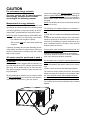
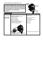
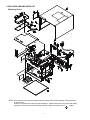
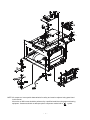
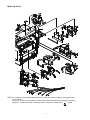
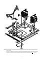
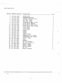
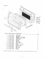
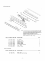
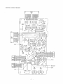
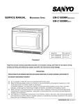
SUPPLEMENT OF SERVICE MANUAL Microwave Oven EM-C160US SERVICE MANUAL SUPPLEMENT for Model EM-C160 SUPPLEMENT OF Microwave Oven SERVICE MANUAL Microwave Oven EM-C160US PRODUCT CODE NO. 437-453-00 See the Service Manual of EM-C180US(SM-640179) PRODUCT NO. Manual. 437-453-00 except the items described in thisCODE Service See the Service Manual of EM-C180US(SM-640179) except the items described in this Service Manual. CAUTION CAUTION WARNING TO SERVICE TECHNICIANS WARNING TO SERVICE TECHNICIANS PRECAUTIONS TO BE OBSERVED BEFORE AND DURING PRECAUTIONS TO BE OBSERVED BEFORE AND DURING SERVICING TO AVOID POSSIBLE EXPOSURE TO SERVICING TO AVOID POSSIBLE EXPOSURE TO EXCESSIVE EXCESSIVE MICROWAVE ENERGY MICROWAVE ENERGY (a) Do not operate or allow(a)theDooven to be or operated with to the open. not operate allow the oven bedoor operated with the door open. (b) Make the on following safety to checks on all ovens to be serviced before the magnetron (b) Make the following safety checks all ovens be serviced before activating theactivating magnetron or otheror other microwave source, and make repairs as necessary: microwave source, and make repairs as necessary: (1)Interlock operation, (2) proper door closing, (3) seal and sealing surfaces (arcing, wear, and other (1)Interlock operation, (2) damage), proper door closing, seal and sealing andorother (4) damage to or(3) loosening of hinges and surfaces latches, (5)(arcing, evidence wear, of dropping abuse. damage), (4) damage to or loosening of hinges and latches, (5) evidence of dropping or abuse. (c) Before turning on microwave power for any service test or inspection within the microwave generating compartments, magnetron, wave guide or transmission and cavitygenerating for proper alignment, (c) Before turning on microwave power forcheck any the service test or inspection within theline, microwave and connections. compartments, check the integrity, magnetron, wave guide or transmission line, and cavity for proper alignment, (d) Any defective or misadjusted components in the interlock, monitor, door seal, and microwave generation integrity, and connections.and transmission systems shall be repaired, replaced, or adjusted by procedures described in this manual (d) Any defective or misadjusted in thetointerlock, beforecomponents the oven is released the owner. monitor, door seal, and microwave generation (e)(i) shall A microwave leakage check to verify the Federal performance be and transmission systems be repaired, replaced, orcompliance adjusted with by procedures describedstandard in this should manual on each oven prior to release to the owner. (For U.S.A) before the oven is releasedperformed to the owner. (e)(ii) A microwave leakage check to verify compliance with the Canadian Regulation, HEALTH AND WELFARE, (e)(i) A microwave leakage check to verifyshould compliance withonthe Federal performance standard should be SOR/79-920 be performed each oven prior to release to the owner. (For CANADA) performed on each oven prior to release to the owner. (For U.S.A) REFERENCE NO.SM-640180 (e)(ii) A microwave leakage check to verify compliance with the Canadian Regulation, HEALTH AND WELFARE, SOR/79-920 should be performed on each oven prior to release to the owner. (For CANADA) REFERENCE NO.SM-640180 FORM # EM-C160 (02/05) CAUTION For microwave energy emission On every service call. A check for microwave energy emission must be made according to the following manner. Measurement of energy emission Measurement must be made with the microwave oven operating at its maximum output and containing a load of 275 ±15 milliliters of tap water initially at 20°± 5° celsius (689°F) placed within the cavity at the center. NOTE:The water container must be a 600 milliliter beaker and made of an electrically none conductive material such as glass or plastic. The cook tray must be in place when measuring emission. A properly operating door and seal assembly will normally register emission no greater than 4 mW/cm2 to allow for measurement uncertainty with the cooking shelf or tray in place. All repairs must be performed in such a manner that microwave energy emission is minimal. Follow the instructions supplied with the detector being used and perform an R.F. emission test around the door front, and all edges and vent of the outer case. The cabinet (wrapper) must be in place and the oven fully assembled. When performing an emission survey, with the meter on FAST RESPONCE, the movement of the detector probe shall not exceed one (1) inch per second. In the area emitting the highest reading, switch the meter to SLOW RESPONSE and take a reading for minimum of three (3) seconds. We recommended the pattern outline shown below when the door surface is surveyed. NOTE: Periodically check to be sure that the probe tip is not worn or dirty. The following U.S. standard applies to microwave ovens: 21 CFR 1030.10, Performance Standard for Microwave Ovens. It requires that the power density of the microwave radiation emitted by a microwave oven shall not exceed five (5) milliwatts per square centimeter at any point 5 centimeters (about 2 inches) or more from the external surface of the oven. All microwave ovens exceeding the emission level of 4 mW/cm2 must be reported to Dept. of Service for microwave ovens and the manufacturer immediately . The owner should be told not to use the microwave oven until it has been repaired completely. If a microwave oven is found to operate with the door open, report to Dept. of Service, the manufacturer and CDRH* immediately. Also tell the owner not to use the oven. *CDRH: Center for Device and Radiological Health. The interlock monitor switch acts as the final safety switch protecting the customer from microwave radiation. If the interlock monitor switch operates properly and the door interlock switch fails, the fuse will blow. If this happens, all interlock switches must be replaced. The contacts of the interlock switches may be welded together. - TABLE OF CONTENTS Specifications ............................................................ 1 Power output Measurement ...................................... 1 Test Procedures .....................................................2 Exploded View and Parts List..........................3 •`10 Control Circuit Board.....................................11 1. SPECIFICATIONS 2. POWER OUTPUT MEASUREMENT Microwave output ................ 1,600W to 160W Frequency ........................... 2,450MHz Power supply ....................... 208V, 60Hz Rated current ...................... 13 Amp. Safety Device ...................... Thermal protector(Magnetron) 150°C(270°F) Open (Thermostat) 80°C(144°F)Close Thermistor (Magnetron) 200°C(360°F) Open 108°C(194°F)Close Thermistor(Duct)................120°C(216°F) Open Fuse (Cartridge Type) ................. 250V 10A Micro switch, Relay Interlock Switch Interlock monitor Switch Door sensing Switch and Relay RL-3 and 4 Max. input time .................... Electronic Digital, up to Manual 10min./Memory 30min. Overall Dimensions ........ 422(W)x540(D)x335(H) mm Oven cavity size ............ 330(W)x330(D)x230(H) mm Effective Capacity of Oven Cavity.........19.1liters Net weight ........................... 32Kg NOTE: The power output specification, 1600W on this model is measured with IEC measurement. The power output is measured with two(2) liters water is equivalent to 1600W in measurement with IEC, when measured with the following power output. (1)1. Fill two beakers, one liter of tap water respectively 2. Use an accurate thermometer and measure each water temperature respectively. (2) Place beakers side by side in center of the ceramic tray. (3) Close the door,set the “TIME” for two minutes. Touch the “START” key and heat the water for exactly two minutes. (4)Take the beakers out, immediately stir the water and measure the water temperatures respectively. (5) Calculate the temperature rise of water in each beaker. Then calculate the average value of the two temperature rises.(ƒ¢t) (6) The teperature rise shall be in the following range; Average Temp. Rise Minimum 20.5°C Maximum 25.1°C Power output is affected by the line voltage under load. (7) For correct Power output measurement, the line voltage under load must be 208±2 Volts. - 1 - 3. TEST PROCEDURES AND TROUBLESHOOTING PRIMARY CAUTION WINDINGS -DISCONNECT THE POWER SUPPLY CORD FROM THE WALL OUTLET WHENEVER REMOVING THE CABINET FROM THE UNIT. PROCEED WITH TESTS ONLY AFTER DISCHARGING THE HIGH VOLTAGE CAPACITORS AND REMOVING THE LEAD WIRES ON THE PRIMARY WINDING OF THE HIGH VOLTAGE TRANSFORMERS FOR LOWER AND UPPER MAGNETRONS. Filament Windings (SEE FIGURE 1) A. TEST PROCEDURES COMPONENT HIGH-VOLTAGE TRANSFORMER Secondary Windings Figure 1 CHECKOUT PROCEDURE RESULT 1) Measure the resistance: With an ohm-meter on R x1 scale. a. Primary winding; b. Filament winding; c. Secondary winding; 2) Measure the resistance: with an ohm-meter on highest scale. a. Primary winding to ground; b. Filament winding to ground; Normal reading: Approximately 1.0 ohms Less than 1 ohm. Approximately 50 ohms Normal reading: Infinite ohms. Infinite ohms. Note: Remove varnish of measured point. Figure 2 - 2 - 4. EXPLODED VIEW AND PARTS LIST Main body Parts-1 NOTE: All component have special characteristics for safety and must be replaced using parts listed in this manual. All service on M/W ovens should be performed by a qualified technician using approved testing equipment. Customers should not attempt replace component marked with a symbol. - 3 - NOTE: All component have special characteristics for safety and must be replaced using parts listed in this manual. All service on M/W ovens should be performed by a qualified technician using approved testing equipment. Customers should not attempt replace component marked with a symbol. - 4 - Main body Parts-2 NOTE: All component have special characteristics for safety and must be replaced using parts listed in this manual. All service on M/W ovens should be performed by a qualified technician using approved testing equipment. Customers should not attempt replace component marked with a symbol. - 6 - NOTE: All component have special characteristics for safety and must be replaced using parts listed in this manual. All service on M/W ovens should be performed by a qualified technician using approved testing equipment. Customers should not attempt replace component marked with a symbol. - 7 -