1
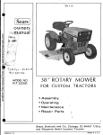
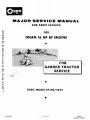
MAdOR SERVICE MANUAL
another free manual from www.searstractormanuals.com
AND PARTS CATALOG
FOR
ON AN 16 HP BF ENGINE
•
• t.
,
•
..
,
.:_
.,
..
/.:.;.
":.,:;
...
. ....
'
.. ..
0 •• " • • • •
.
..
. .
FOR
GARDEN TRACTOR
SERVICE
;..
••
•
BASIC MODEL BF-MS/2425
•
965-0250
Prml ed in U. S . A .
9AD74
Replaces 8AB73
another free manual from www.searstractormanuals.com
another free manual from www.searstractormanuals.com
TABLE
UL
SER ICE
FOR
BF
GARDEN TRACTOR ENGINES
WE SUGGEST THIS BOOK BE KEPT HANDY FOR READY
REFERENCE, EITHER FOR ORDERING PARTS OR MAKING
ADJUSTMENTS.
1
OF
CONTENTS
GENERAL
INFORMATION
2
SPECIFICATIONS
3
DIMENSIONS AND
CLEARANCES
4
ASSEMBLY
TORQUES
4
ENGINE TROUBLE
SHOOTING
S
OIL SYSTEM
6
FUEL SYSTEM
8
rGNITlON. AND
BATTERY
CHARGING
12
STARTINO
SYSTEM
lS
ENGINE
DISASSEMBLY
18
PARTS CATALOG
29
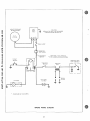
ENGINE WIRING
DIAGRAM
44
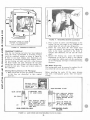
GENERAL INFORMATION
another free manual from www.searstractormanuals.com
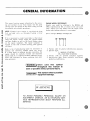
This manual contains proper information for the servicing and overhaul of your Onan engine. Use the parts
catalog in the rear portion of this book to help you with
disassembly and assembly procedures.
ENGINE MODEL REFERENCE
Identify your model by referring to the MODEL and
SPEC (specification) NO. as shown on the unit nameplate. Always use this number and the engine serial
number when making reference to your engine.
NOTE: Flywheel end of engine is considered the front.
Left and right sides are determined looking at front
of engine.
How to interpret MODEL and SPEC NO.
If it is necessary to contact your dealer or the factory
about this engine, always supply the complete Model
and Spec Number as well as the Serial Number shown
on the engine nameplate. The engine nameplate is
located on left side of blower housing (end opposite
oil filter),
rrT1
1. Factory code for general identification purposes.
2. Specific Type:
S - MANUAL STARTING
MS - ELECTRIC STARTING
3. Factory code for optional equipment supplied.
4. Specification (Spec Letter) advances with factory
prod uchon modification.
Refer to the Troubleshooting Guide for assistance in
locating and correcting troubles which may occur.
If a major repair or overhaul becomes necessary, the
engine should be carefully checked and necessary
repairs made by a competent mechanic. Maintain factory
limits and clearances as shown, replacing worn parts
when necessary.
IWARNING'
Onan uses this symbol
throughout this manual to
warn of possible serious personal Injury.
~ Thi~
symbol refers to possible
equipment damage.
WARNING
I
TO A VOID POSSIBLE PERSONAL INJURY OR
EQUIPMENT DAMAGE, AN AUTHORIZED SERVICE REPRESENTA TlVE MUST PERFORM ALL
SERVICE.
2
another free manual from www.searstractormanuals.com
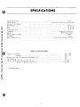
SPEC I FICA liONS
. . . . . . . . . . . . ..
Onan
Four Cycle, Air-Cooled, Two Cylinder
Engine Manufacturer. .
Engine Design. . . . .
Horsepower at 3600 rpm
Displacement
Bore . . . . . . . .
Stroke . . . . . . •
Compression Ratio
Crankshaft. . . . .
Valves . . . . . .
Bearings (Main and Rod)
Oil Capacity . . . . .
Battery Charging System
16
40.3 cu. in.
3-1/8 inch
2-5/8 inch
7 to 1
Horizontal, Ductile Iron
Mechanical, Poppet
. . . . . ..
Sleeve
. . . . . .•
4 pints
12 volt, 15 amp Flywheel Alternator
TUNE·UP SPECIFICATIONS
.007 - .009
Tappets (Cold) Intake . . . . . . • .
Exhaust . . . . . . . • . . . . . . . .
Breaker Point Gap (Full Separation and Engine Cold)
Spark Plug Gap . . . . . . . . . . . • . . • . . •.
Ignition Timing (Engine Running Hot Setting)
(Engine Not Running, Cold Setting)
.012 - .014
*
* - Preferred setting.
3
.025 "
.025
21 ° BTC
25 °BTC
DIMENSIONS AND CLEARANCES
All dimensions and clearances given at room temperature of 70°F.
All values in inches unless otherwise specified.
Minimum
Maximum
another free manual from www.searstractormanuals.com
CAMSHAFT AND CRANKSHAFT
Crankshaft Main Bearing Journal to Bearing Clearance
End Play . . . . .
Camshaft Bearing to Camshaft . . . . .
Camshaft End Play . . . . . . . . . . .
* Crankshaft Rod J oumal to Rod Bearing
Connecting Rod End Play
Timing Gear Backlash .
Oil Pump Gear Backlash
* Crankshaft
0.0025
0.006
0.0015
0.003
0.0020
0.002
0.002
0.002
0.0033
0.016
0.003
0.005
0.0002
0.0002
0.010
0.0004
0.0007
0.020
0.001
3.1245
1.9992
1.6252
0.003
3.1255
2.0000
1.6260
0.0038
0.012
0.0030
PISTON AND CYLINDER
Piston Pin in Piston .
Piston Pin in Rod . .
* Piston Ring Gap in Cylinder
Piston Clearance in Cylinder-Measured .10 Below Oil
Control Ring, 90 ° from Pin . . . . . . . . . .
Cylinder Bore - Standard Size . . . . . . . . . .
Crankshaft Main Bearing J oumal - Standard Size
Crankshaft Rod Bearing Journal - Standard Size
TAPPETS AND VALVES
*Valve Seat Width.
* Valve Face Angle . .
* Valve Seat Angle
Valve Stem to Guide - Intake
Valve Stem to Guide - Exhaust
Tappet to Cylinder Block Clearance
Tappet Adjustment (Cold)
* Intake.
*Exhaust . . . . . . . .
1/32
44 °
4') °
1/8
0.0010
0.0035
0.0015
0.0025
0.0040
0.0030
0.007
0.012
0.009
0.014
* - Frequently used overhaul values.
ASSEMBLY TORQUES AND SPECIAL TOOLS
BOLT TORQUE
Gearcase Cover . . . . . . . . . . .
Cylinder Head Stud Nuts (Cold) .
Rear Bearing Plate Screws ..
Starter Mounting Bolts . . . . . . .
Connecting Rod Bolt . . . . . . . .
Flywheel Cap Screw . . . . . . . .
Other 5/16 "Cylinder Block
Stud and Nuts . . . . . . . . . .
Oil Base . . . . . . . . . . . . . . .
. .... .
Manifold Mounting Screws . . . . . . . • . . . . .
Oil Pump . . . . . . . . . . . . . . . . . . . . . . .
FT.· LB.
8 - 10
14
25
18
14
35
-
16
27
20
16
40
The following special tools are available from Onan,
for further information see Tool Catalog 900-0019.
Valve Seat Driver
Valve Guide Driver
Oil Guide and Driver
Combination Bearing Remover (Main and Cam)
Combination Bearing Driver (Main and Cam)
Flywheel Puller
8 - 10
18 - 23
6 - 10
7- 9
4
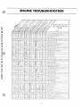
ENGINE TROUBLESHOOTING
b
another free manual from www.searstractormanuals.com
el"
GASOLINE ENGINE
TROUBLESHOOTING
GUIDE
CAUSE
STARTIHC SYSTEM
•
•••
•
L .... se o. CO<tOd,,'" Batle'Y C""" " CUOft
Low a' Q'SC'""'lcd 8llne.)'
•
•
•
•
•
• •
••
•
ICHITIO... SYSTEM
••••
• ••
•
•
.
I.
•
•• •
•
I.
Co d
Il[nll ' OI'
0'
s.- Itln l
Conde"''' '
QUI 01 Fuel· Ch,,(I,
Lean F"" I Mlxlure · Re~dl ""
• ••
• •
••
• ••
•
•• •
• •
•e e•
•
DI
ea"
FUEL SYSTEM
• •
•
••
I.
Imprope ' G-co
.... arn Po ,n ..
En,,"e Floc.IeJ
P .... r Quail,), Fuel
• •
•
••
•
•
•
0, ..... Fuel F l ite!
e
DeleChvl! Fu(" Pumo
INTERNAL EHGINE
••
••
.-
•
COOLING SYSTEM I AU\ COOI.EO)
I I I I I I I • I I I • I I 1- •• I
1 I
I I
I
I
I
I
I
I
I
I
•
-•
••
•
- -
• •
••
•• •
•
l~
11-.+-1_11~~p~""~'~"'~"~C,,,~c~ul~
a" "~
"" ~______________-i
I TT T I OU'l' '" Q llv Coolo" J[ FIns
T
I Blown HU d Cu\e l
I
1.-'.' , I'
I T.T T Ie. I
I •
I
I I I ••• I
I
J
COOLING SYSTEM (WATER COOLEO I
...
In sutl. c ... ,,, CODIMI
...
•
•
•
•
"'ald P •• U p l R,," trICied
O.",, <.. ~ ..
c...k","
__ ._.
-t
~~~~~~~~~--4~-~:.L-J--L~~.~~~.:~~~.~-J-=.~J-~~~8gl~D~w~
~ H~e~.a~ld~Ga~'k~'''~I_________________
•
••
•• •
• I. I-• •
•
•
•
I·
• •
-
-
L UBR ICA ION S ST M
Oete cu w. Oil CAl.l t e
• ••
•
•
•
•
•
I·
-•• •
••
• •• ••
•
•
v"i.. " S.uc k
Fau lty 0 11 Purr:>
Dluy Oil 0' 'F-ilre ,
0 11 T .... L. lh l 0' D.'!~L __
O d Le .. ,, 1 Low
0-" Too HI:nvw
OU 'Y CII,nlc.utl Bt eAlhe, VnlYe
R.I ,.. I
---
THROT TL E AND GOVER OR
••
LI~ k 4l re Wlltn or DI,c.ann" CIl'd
__
Gove rn or Sp ron E Sen s lI,vlIY Too G,e4l1
•
5
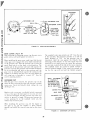
OIL SYSTEM
CRANKCASE OIL
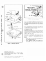
~ Do not overfill crankcase. Do not use
another free manual from www.searstractormanuals.com
Change crankcase oil every 50 operating hours and
only when engine is warm. (Exc~ption« Drain initial
oil fill at 25 operating hours.)
~ service DS oil. Do not mix brands
or grades of motor oil. Engine damage could result
from mixing non-compatible oils.
To drain, remove the 1/2 inch pipe plug on the rear
corner of the oil base. After oil drains, replace the
pipe plug and refill crankcase with 4 pints (4-1/2 if
equipped with filter) of a good quality detergent oil.
Oil must meet or exceed the API (American Petroleum
Institute) designation SE or SE/CC; this oil was
formerly designated as MS, MS/DG or MS/DM (Figures
1 and 2).
For temperatures above 30 "F, use SAE 30 oil; for
temperatures below 30 of, use 5W30 or lOW.
In extremely dusty conditions or in very cold weather,
change oil at least every 25 hours of operation.
ALWAYS REPLACE
TIGHTLY OR OIL
LEAKAGE MAY OCCUR
OIL DRAIN - BOTTOM SIDE
REMOVE 1/2 INCH PIPE
PLUG TO DRAIN
FIGURE 2.
I
OIL DRAIN LOCATION
fULL
~ / CAU110N- DO NO 1 OVLRI-Ill
f - ADD
FIGURE I.
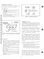
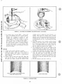
Crankcase Breather: This engine uses a crankcase
breather valve for maintaining crankcase vacuum. No
maintenance is generally required. If the crankcase
becomes pressurized as evidenced by oil leaks at the
seals, clean baffle and valve in a suitable solvent.
See Figure 3.
ONE PINT
CRANKCASE OIL FILL
6
CRANKCASE TURNED!!!)
---ON LEFT SIDE'-
another free manual from www.searstractormanuals.com
B R EA THE R H OS E - -
OIL
FIGURE 4. OIL PUMP ASSEMBLY
Check the oil pump thoroughly for worn pa rts. Oil the
pump to prime it before reinstalling. E xcept for ga ske t s
a nd sucti on cup, the com ponen t parts of the pump a re
not available individu a ll y . Insta ll a ne w pump a sse mbl y
if required.
FL AT
W AS H ER ~
~
If new oi l pump gas kets a re installed, they sh ould be
the same thickness a s those removed. A gas ket kit with
var ious thic kness ga s ke ts is av a ilable .
RE E D VALVE
/
BREATHER BAF F LE
OIL BY·PASS VALVE
The by -pass va lve (l ocated to the rig ht and behind gear
c ove r), c ontrol s oil pre ssure by a llowing excess o il t o
flow directly bac k to the c ra nkc ase. Norm a lly the val ve
begin s to open a bout 3 0 ps i .
The valve is n on-adjust a ble a nd normall y nee ds no
maintenan ce. To det e rmine if a bn orma l (hi gh or low) oi l
pres sure is c a us ed by a sticky plunge r inspe ct as
follows :
1. R e mov e 3/8 x 24 x 1 ca p s crew l oca ted behind gea r
c over a nd under gover nor a rm.
2. Re move spring and plunge r with a ma gne t tool.
Clea n plun ger and spring with a s uit a ble so lvent
and re insta ll.
FIGURE 3.
CRANKCASE BREATH ER
PRESSURE LUBRICATION
P ress ure l ubric a te d e ngines use a n oi l pump to lubri c a t e e ngine pa rts. If oil pressure is low, the pump
s hould be c he cke d.
To re move the oil pump, it is necess a ry to det ac h the
intake cup a s sembly, as ill us trate d in Figure 4.
7
FUEL SYSTEM
Check the adjusting needles and nozzle for damage. If
float is loaded with fue 1 or damaged, replace it. The
float should fit freely on its pin without binding.
another free manual from www.searstractormanuals.com
CARBURETOR CLEANING AND INSPECTION
To clean the carburetor, soak all components thoroughly
in a good carburetor cleaner, following the manufacturer's instructions. Be sure to remove all carbon from
carburetor bore, especially in the area of the throttle
valve. After soaking, c lean out all passages with
filtered, compressed air.
Check the choke and throttle shafts for excessive side
play and replace if necessary.
Carburetor repair and gasket kits are available
from your nearest On an Parts Center.
Note:
SHAFT-~~
CHOKE
AND LEVER
d
~
CHOKE FLY
~
~
""
,
-
SLEEVE
ASSEMBLY
NOTE
ON SOME MODELS ENGINES FUEL
PUMP IS MOUNTED DIRECTLY TO
CARBURETOR
LEVER
ASSEMBLY
.
FUEL PUMP (SEE INSERT)
THROTTLE STOP SCREW
o fA
~
/
THROTTLE SHAFT
AND LEVER
~
B,
GASKET
THROTTLE FLY
CARBURETOR
INLET PLATE
FUEL INLET
FIGURE 5.
EXPLODED VIEW OF CARBURETOR
8
another free manual from www.searstractormanuals.com
PUMP
EXPLODED VIEW OF FUEL PUMP
FIGURE SA.
EXPLODED VIEW OF FUEL PUMP
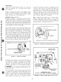
CARBURETOR DISASSEMBLY AND REPAIR (Figure S)
Removal:
1. Remove air cleaner and hose.
2. Disconnect governor and throttle linkage, choke
control and fuel line from carburetor.
3. Remove the four intake manifold capscrews and
lift complete manifold assembly from engine.
4. Remove carburetor from intake manifold.
IMPORT ANT:
conditions.
A lways work on carburetor
In
clean
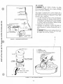
Replacing Needle and Valve Seat:
FIGURE 6.
1. Remove four screws from top of carburetor and
lift off float assembly.
2. Invert float assembly as shown in Figure 6.
3. Push out pin that holds float to cover.
4. Remove float and set aside in a clean place. Pull
out need le and spring.
5. Remove valve seat and replace with a new one,
making sure to use a new gasket.
6. Install new bowl gasket.
7. Clip new needle to float assembly with spring
clip. Install float.
FLOAT ADJUSTMENT
Fuel Pump Disassembly (Figure SA):
1. Remove vacuum line and fuel line.
2. Remove the two fuel pump attaching screws.
3. Grasp pump and carefully pull apart. Diaphragm,
plunger, return spring, pump body and mounting
gaskets will now be loose.
4. Internal fuel pump parts are available in a repair
kit. Check Parts Catalog for correct part number.
Carburetor Float Adjustment:
1. Invert float assembly and casting.
2. With the float resting lightly against the needle
and seat, there should be 1/8
clearance between
the bowl cover gasket and the free end of the
float.
3. If it is necessary to reset the float level, bend
the float tangs near the pin to obtain a 1/8"
clearance (Figure 6).
U
5. Ensure that clamps are replaced on fuel line.
~ Use care when reassembling .pump;
all parts must be perfectly alIgned,
or pump will leak, creating a fire hazard.
9
CARBURETOR ADJUSTMENTS
The carburetor has a main fuel valve adjusting screw
a nd an idle valve adjusting screw (Figure 7). A low
speed adjustment screw is shown in Figure 8.
Initial Adjustment:
1. Turn main fuel valve clockvrise until it just closes.
~
another free manual from www.searstractormanuals.com
CAUTION
-
Valves may be damaged by turn.
tng
th
em 'tn too f ar.
THROTTLE
STOP
SCREW
SIDE VIEW
FIGURE 8.
MAIN FUEL
(HIGH SPEED)
ADJUSTMENT
These engines are adapted for use where a wide range
of speed settings is desired. Engine speed is controlled at any given point between minimum and
maximum b~ simply shifting the throttle lever on the
dash panel until the desired speed is reached.
The design of the variable speed governor gives an
automatic decrease in sensitivity when the speed is
increased and the result is good stability at all speeds.
IDLE
ADJUSTMENT
A reliable instrument for checking engine speed is
required for accurate governor adjustment. Engine
speed can be checked with a tachometer.
REAR VIEW
Check the governor arm, linkage, throttle shaft, and
lever for binding condition or excessive slack and
wear at connecting points. A binding condition at
any point will cause the governor to act slowly and
regulation will be poor. Excessive looseness will
cause a hunting condition and regulation will be
erratic. Work the arm back and forth several times
by hand while the engine is idling to check for above
conditions.
Final Adjustment:
1. Turn main fuel valve in until engine misses (lean
3.
4.
S.
LOW SPEED ADJUSTMENT
GOVERNOR (Figure 9)
FIGURE 7. MAIN FUEL AND IDLE VALVE ADJUSTMENT
2.
--------
~
2. Now open main fuel valve 1-1/8 turns counterclockwise.
3. Close idle valve in same manner and open it 1/2 to
one turn (counterclockwise).
4. This initial adjustment will permit engine to start
and warm up prior to final adjustment.
LOW SPEED SET
ON GOVERNOR
LlNKAGE- SMALL
GAP HERE AT NO
LOAD
SET LOW SPEED ADJUSTMENT
SO ENGINE RUNS AT 1200 RPM
IN "SLOW" POSITION.
mixture), then turn it out past the point where
engine runs smoothly until engine runs unevenly
(rich mixture). Turn valve to mid-point between
lean and rich so engine runs smoothly.
Hold engine at idle position and set low speed
adjustment screw (Figure 8) until a fast idle is
obtained (1200 rpm).
Hold throttle in idle position and turn idle adjustment valve in (lean) and out (rich) until engine
idles smoothly.
Reset low speed adjustment screw so engine
idles at 1200 rpm.
Re lease throttle - engine should accelerate without
hesitation. If engine does not accelerate properly,
readjust main fuel valve by turning out slightly.
If governor is hunting or not operating properly, adjust
as follows and as shown in Figure 9.
1. Disconnect linkage (A) from one of holes (C).
2. Push linkage (A) and governor arm (B) as far back
(toward carburetor) as they will go.
3. Holding linkage and governor arm toward direction
of carburetor, insert end of linkage into whichever
hole (C) (in governor arm) lines up the closest.
The governor control spring is factory set in the top
hole of the governor control shaft bracket. To increase
the sensitivity, move the spring loop into the hole
nearest the control shaft. To decrease the sensitivity,
move the spring outward. After the sensitivity has
been set, adjust the low speed with the adjustment
screw on the control wire bracket.
Important: Do not open more than 1/2 turn beyond
maximum power point.
10
AIR CLEANER
~ If
c leaner becomes too dirty,
will not rece ive s uffic ie nt
a ir to run properly . Symptom s : Loss of power, fl ooding,
hard to start a nd ov erheating.
a ir
~ e ngine
THROTTLE S TOP
SCREW
This engine is equipped with a paper elel\1~nt and a
polyurethane precleaner that must be removed, cleaned
and oiled every 25 hours of operation, or more under
extremely dusty conditions.
another free manual from www.searstractormanuals.com
1. To clean pre-cleaner wash in wa ter a nd detergent
referring to Figure 10. Remo ve excess water by
squeezing like a sponge and allo w to dry thoroughly. Distribute three tablespoons of SAE 30 e ngine
oil evenly arou nd the pre-cleaner. Kn ead into and
wring excess oi l from pre-cleaner.
2. Depending on conditions in which the t racto r is
operating, the inner paper element should be re placed wheneve r it becomes excessively dirty or
oily.
GOVERNOR SPRING
~ N ever run the e ng in e with th e a ir
L~ cleaner re moved. Dirt will e nter
LOW SPEED / /
STOP ADJUSTMENT
the e ngine and score the cy linders.
,•
FIGURE 9. GOVERNOR ADJUSTMENTS
I
~-----------------------------------------------------------I:--------~
NUT
1. WASH
2. SQUEEZE DRY
3. COAT WITH OIL
4. INSTALL
POLYURETHANE
PRE-CLEANER
PAPER
ELEMENT
BASE
HOSE
INTAKE TUBE
B82
FIGURE 10.
AIR CLEANER ASSEMBLY
11
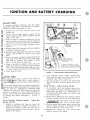
IGNITION AND BATTERY CHARGING
BREAKER POINTS
another free manual from www.searstractormanuals.com
To maintain maximum efficiency from the engine,
change the breaker points every 200 hours of operation.
Proceed as follows when engine is cold:
1. Remove the two screws and the cover on the
breaker box.
2. Remove the two spark plugs so engine can be
easily rotated by hand. Check condition of spark
plugs at this time.
3. Refer to Figure 11. Remove mounting nut (A) and
pull the points out of the box just far enough so
screw (B) can be removed and leads disconnected.
4. Remove screw (C) and replace condenser with a
new one.
5. Replace points with a new set but do not completely tighten mounting nut (A).
6. Remove the air intake hose that connects to blower
housing. This provides an access to view timing
mark.
7. Rotate the engine clockwise (facing flywheel) by
hand until the 25 0 BTC mark on gear cover aligns
with mark on flywheel. Turn another 1/4 turn
(90 0 ) to ensure points are fully open.
8. Using a screwdriver inserted in notch (D) on the
right side of points, turn points until gap measures
.025 " with a flat thickness gauge. (Be sure feeler
is clean.) Tighten mounting nut and recheck gap.
PREFERRED
,\ETHOD
®~
REMOVE HOSE AND VIEW
TIMING MARKS THROUGH
THIS HOLE
CORRECT TIMING IS 21 BTC
HOT SETTING ENGINE RUNNING
2S"BTC COLD SETTING - STATIC
9. Check ignition timing.
FIGURE II. IGNITION AND TIMING ADJUSTMENT
2
Turn crankshaft against rotation (counterclockwise) until the points close. Then slowly turn the
crankshaft with rotation (clockwise).
3. The lamp should go out just as the points break
which is the time at which ignition occurs (25 0
BTC).
IGNITION TIMING
The timing on the engine is preset at the factory. A
point box is used, however a
slight timlpif~:~nge could be made by adjusting points.
non-mov<l.l:tl~.,"IIteaker
\':"i
The engine is equipped with an automotive type battery
ignition system. Both spark plugs fire simultaneously,
thus the need for a distributor is eliminated. Spark
advance is set cold at 25 0 BTC (before top center) and
should be maintained for best engine performance.
Always check timing after replacing ignition points or
if noticing poor engine performance.
Proceed as
follows:
Timing Procedure (Preferred Method) Running and Cold:
Timing Procedure - Engine Running and Hot:
1. To accurately check the ignition timing, use a
timing light when engine is running. Connect the
timing light according to its manufacturer's in~
structions. Either spark plug can be used as they
fire simultaneously.
2. Remove the air intake hose that connects to blower
housing to provide an access to view timing marks.
[--Wi-RNINGJBe
sure
.posIllOn
Engine Not
1,0._ _ _ _ _ _ _
1. Connect a continuity test lamp set across the
ignition breaker points. Touch one test prod to the
breaker box terminal to which the coil lead is
connected and touch the other test prod to a good
ground on the engine.
tractor is in the neu~ral
before startIng engme.
3. Start the engine. When engine warms up check the
ignition timing. The mark on the flywheel should
line up with the 21" mark on the cover.
4. Replace hose, breaker box cover and any other
hardware removed from engine.
12
~
This engine uses a 12 volt, negative
system. Alternator must be
connected to battery at all times when engine is running. Do not reverse battery cables. Damage to regulator or ignition coil could result if cables are reversed.
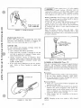
~ ;iround
Battery Inspection: Check battery cells with a hydrometer. The specific gravity reading should be approximately 1.280 at 80 OF. (Figure 14).
If cells are low on water, add distilled water and recharge. If one cell is low, check case for leaks.
Keep the battery case clean and dry. An accumulation
of moisture will lead to a more rapid discharge and
battery failure.
Keep the battery terminals clean and tight.
After
making connections, coat the terminals with a light
application of petroleum jelly or non-conductive grease
to retard corrosion.
another free manual from www.searstractormanuals.com
SPARK PLUG GAP
0.025" GASOLINE
FIGURE 12. SPARK PLUG GAP
SPARK PLUGS (Figure 12)
Remove both spark plugs 'and install new ones every
100 hours. Use ONAN No. 167-0241 or Champion H-8.
Check to be sure spark plug gap is set at .025 " .
SPECIFIC
GRAVITY READING
SHOULD BE
1.280 AT 80° F.
IGNITION COIL
To test primary and secondary windings within the
ignition coil proceed as follows:
1. Use a Simpson 260 VOM or equivalent.
2. Place back lead on ground H terminal of coil and
red lead to positive (+) terminal. Primary resistance should read 3.87 ~ 4.73 ohms.
3. Change resistance setting on ohmmeter. Place
ohmmeter leads inside of spark plug cable holes
(F igure 13). Secondary resistance should read
12,600 - 15,400 ohms.
4. If any of the above conditions are not met, replace
coil.
Refer to Parts Catalog for correct part
number.
FIGURE 14. SPECIFIC GRAVITY TEST
FLYWHEEL ALTERNATOR (Figure 15)
This unit is equipped with a permanent magnet flywheel
alternator and solid-state voltage regulator-rectifier
(output control). As with all solid-state electrical units,
precautions are necessary when servicing. Observe the
following.
Precautions:
1. Do not connect battery cables in the wrong polarity.
2. Do not short together alternator stator leads.
3. Do not run wi thout a battery. Damage will occur to
regulator and battery ignition coil.
Preservice Checks:
1. Check for a good ground between equipment and
regulator-rectifier case.
2. Be sure output control plug (connector) is properly
inserted into stator receptacle. This means the
plug must push in and solidly bottom in the receptacle to eliminate any resistance due to a poor
connection. Keep it clean and tight.
3. Check battery and its connection to be sure it
is serviceable.
NOT E: Charging system tests reqUIre a fully charged
battery.
FIGURE 13. COIL TEST
13
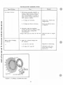
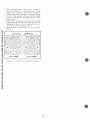
TESTING BATTERY CHARGING SYSTEM
Test
Type of Failure
another free manual from www.searstractormanuals.com
No c ha rge to battery.
Results
1. With battery connecte d, c heck B, to
Ground voltage with DC voltmeter. If
voltmeter reads 13.8 volts or higher,
place load (headlights) on battery to
reduce battery voltage to below 13.6
volts. Observe ammeter.
a.
1£ charge rate increases.
System okay. Battery was
charged fully.
b.
If charge rate does not increase.
Check for defective stator
or regulator.
2. Disconnect plug from re gulator~
rectifier and test AC voltage at plug
(two white wires, reading back
into alternator),
Voltage reads much less than 28 volts AC.
Battery a lways charging
at high rate.
'.,
VOLTAGE RE
87 .. - 1
FIGURE
15.
Defective Stator or magnet
gtoup.
1. Check B+ to Ground voltage with
DC voltmeter.
a. If over 14.7 volts DC
Regulator not functioning.
b. If under 14.7 volts DC
Alternator system okay.
Check battery charge ma y be low.
ULA TOR
FLYWHEEL ALTERNATOR SYSTEM
14
another free manual from www.searstractormanuals.com
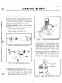
STARTING SYSTE
ELECTRIC STARTER (Spec A & Spec B)
Normally the starter will require little or no service
other than possible brush replacement. However, if
through accident or misuse, the starter requires service
or overhaul, the following information will provide the
information necessary to perform this service.
STARTER DISASSEMBLY (Figure 16, Spec A; Figure
16A, Spec B)
1. Remove the through-bolts and separate the end
cap, the housing and the armature.
2. Disassemble the drive assembly and the drive end
cap by loosening the self-locking nut.
FIGURE 17. TESTING ARMATURE FOR GROUNDS
FIGURE
16. STARTER DISASSEMBLY (SPEC. A)
FIGURE
16A. STARTER DISASSEMBLY (SPEC. B)
2. Testing Armature for a Short Circuit: Use a growler
for locating shorts in the armature. Place armature
in growler and hold a thin steel blade (e.g. hac~saw
blade) parallel to the core and just above it while
slowly rotating armature in growler. A shorted
armature will cause the blade to vibrate and be
attracted to the core. If armature is shorted, replace
with a new one (Figure 18).
3. Inspecting For An Open Circuit in Armature: The
most likely place to check for an open circuit is
at the commutator riser bars. Inspect for loose
connections on the points where the conductors
are joined to the commutator bars (Spec A only).
HACK SAW
BLADE
GROWLER
INSPECTION OF PARTS (Spec A & Spec B)
1. Testing Armature for Grounds: Touch armature
shaft or core and the end of each commutator bar
with a pair of ohmmeter leads. If the ohmmeter
reading is low, it indicates a grounded armature.
Replace grounded armature. See Figure 17.
FIGURE 18. TESTING ARMATURE FOR SHORT CIRCUITS
15
another free manual from www.searstractormanuals.com
Testing Field Coils for Open Circuit !Spec A Only}
Place one lead on the connector and the other on
<1 cleem spot on the brushholder. If the ohmmeter
reading is high, the field coil is open. Check the
other three brushholders in the same manner. See
Figure 19.
S. Testing Field Coils for Grounds: (Spec A Only)
Place one lead on the connector and the other on
a clean spot on the frame after unsoldering shunt
fie ld coil wire. If the ohmmeter reading is low,
the fie Ids are grounded, either at the connector or
in the windings.
FIGURE 21. TESTING BRUSH SPRING TENSION
ST ARTER ASSEMBLY
Reassembly is the reverse of disassembly. When reassembling, observe the following:
1. Wipe off any dirty parts with a clean cloth or blow
clean using filtered compressed air.
NOT E: Bearings must not be immersed in cleaning
fluid. These parts should be cleaned with a brush
dipped in clean engine oil.
2. Apply SAE 10W-30 oil on the armature shaft, spline
and bearings.
FIGURE 19. TESTING FIELD COILS FOR OPENS
REASSEMBLY (Spec B only)
6. Brush Inspection: If brushes are worn shorter than
1/4 inch, replace them. Check to see that brushes
move smoothly in the brush holders. See Figure 20.
WEAR
EJ
LlMITII
--- --
SPEC A
FIGURE 20.
T
112"
~
1. Assemble brushes so that chamfered side is away
from the brush springs and position the brush
shunts so that they will not contact the commutator or commutator end cap.
2. Torque bolts (Figure 16(a), item 3) to a value of
3-3-1/2 ft-lbs.
3. Torque nut (Figure 16(a), item 4) to a value of
4-5 ft-lbs .
4. Apply a thin film of grease to the commutator end
of the armature shaft and to the portion of the shaft
that contacts the bearings. Apply a generous film
of Lubriplate (( Aero" grease to the shaft thread.
5. Torque stop nut (Figure 16(a), item 1) to a value
of 20-25 ft-Ibs. Hold armature in a vise.
6. Torque thru-bolts (Figure 16(a), item 2) to a value
of 4-1/2 - 6 ft-Ibs.
T
. 35
1
WEAR
LIMIT
SPEC B
BRUSH WEAR LIMIT
7. Brush Spring Inspection (Spec A only): Check
brush spring tension as shown in Figure 21. If
spring tension reads 17 to 25 ounces, the spring
is satisfactory.
~ Do not exceed the rated voltage of the
~ motor
(12-VDC). Excessive voltage
could demagnetize the motor permanent magnet field.
16
another free manual from www.searstractormanuals.com
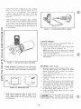
I
MOTOR INPUT
STUD
AMMETER
"<TCH
1
BATTERY
VOLTMETER
NOTE: Battery to starter wire
size at least #10. Max.
length6ft.
12-Y
I
I
CRANKING
MOTOR
L-______________L-________________________--J
FIGURE 22.
NO LOAD TEST
NOTE: 1.
To ensure good electrical contact, make
sure starter to engine mounting surfaces are free
of dirt or oil.
2. When tightening attaching bolts and nut, starter
gear should be held into ring gear to assure proper
backlash.
INSPECTING REASSEMBLED STARTER
1. No Load Test: Connect the starting motor as
shown in Figure 22.
3. Battery to starting motor wire must be tightened
securely.
The values for this test are as follows:
~ Starter motors ar~ not designed for
~ contmuous operatIOn. Do not operate
Spec B
Spec A
12.0 volts
Battery Voltage. . . . . . . ..
11.5 volts
4,800-6,100
RPM . . . . . . . . . . . . . 8000 rpm (min)
32 amperes
Maximum Current Draw . . . 25 amperes
more than 30 seconds per "ON" cycle. Do not operate
starter more than 10 seconds in a stall condition if
engine will not rotate. Serious damage could result if
these time limits are exceeded.
17
ENGINE DISASSE
BLY
another free manual from www.searstractormanuals.com
VALVE SYSTEM
a bl e, be cause the s ha rp contac t ma y be destroye d. Thi s
is es pec iall y importa nt wh e re s te llite faced va lves a nd
sea ts a re used. Va lve faces s h o uld be fini s hed in a
mac hine to 44 °. Va l ve seats s hould be ground with a
45 0 s tone and the width of the seat band s hould be
1/32 u to 3 / 64" wide . Grind only enough to ass ure
pro per seating.
Pro pe rly sea te d valves a re esse ntia l to good e ngine
pe rforma nce . The aluminum cy linde r heads are remo va a ble for va lve se rvicing . Do not use a pry to loos en the
cy lind e r head ; rap s harpl y on the e dge with a soft
faced ha mm e r, taking care not t o brea k any cooling
fin s . A conventional typ e va lve spring lifter may be
used whe n removing the va lve s pri ng locks, which a re
of the s plit type. Clean a ll carbo n de posits from th e
cyl i nd er heads, piston tops , va lves, guides, etc. If a
va lve face is burned or wa rpe d , or the stem wo rn,
in sta ll a ne w valve. Refe r to Fi gure 23 .
Re move all grindin g compound from engine pa rts a nd
place e a ch valve in its pr ope r location. Check each
va lve for a tight s eat, USing a n air pres s ure test in g
too!. If s uch a tool is not ava ila ble , make pe ncil ma rk s
a t inte rva ls acros s the va lve face and obse rve if th e
ma rks rub off uniforml y whe n the valve is rota te d pa rt
of a turn against the seat.
Worn va lve s tem guide s may be repl aced from ins id e
th e v a lve c ha mber. Val ve loc ks a re s plit , tapered t ype,
the sma lle r diameter of whic h mus t fa ce toward the
va lve he ad. Tappets are a ls o re pl aceable from the va lve
ch a mb e r, a fter first removing the valve assembli es .
Lightly oil the valve s te ms a nd assemble a ll pa rts
re moved.
The va lve face angle is 44 °. The va lve seat angle is
45 0 . T hi s 1 ° interfere nce a ng le results in a sha rp
seat ing s urface betwee n the va l ve a nd the top of the
val ve s e a t. The interfe re nce a ngl e me thod of grindin g
va lves minimizes fa ce de pos it s a nd lengthens va lve
life .
Th e positive type va lve rota to rs prolong va lve life
a nd decrease valve re pa irs . Whe n functioning prope r! y,
the va lve is rotate d a f rac ti on of a turn each time it
ope ns . While at ope n pos iti on, th e val ve mus t rota te
free ly, but in only one direc ti on. If rotators a re fa ulty ,
in s ta ll new rotators .
The va lves s hould not be ha nd la pped, if at all avoid-
VALVE
WRONG
NOTE - USE A STANDARD
AUTOMOTIVE TYPE WRENCH
TO ADJUST THE TAPPETS.
_~
NOTE - SEE VALVE TAPPET
CLEARANCES IN TEXT
.
f4.
r.4::l
Ir''''':
iJALVE ROTATOR
VALVE SPRIN~
VALVE SEAT
fJ~~~f:Y ~
I
V1
.....
""
V .LV
~~~.~~.,::.
O-RING'
(INTAKE VALVE
., , ONLY)
I
FIGURE 23.
VALVE SYSTEM
18
":.-~~
~~~
,. ..-~
.'- ~
V AL V E SPRING
WASHER LOCK
another free manual from www.searstractormanuals.com
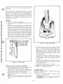
Tappet Adjustment: The engine is equipped with ad-
FLYWHEEL
justable valve tappets. The valve tappet clearance
should be checked and adjusted, if necessary, at least
every 400 operating hours or when poor engine performance is noticed. Adjust the valve clearance only when
engine is at ambient temperature. Proceed as follows:
Removing the flywheel is a relatively simple process,
but the following procedure mus t be followed to avoid
damage to the gear case and possible injury to the
operator.
1. Remove ignition key from tractor to prevent acci-
1. Turn the flywheel mounting screw outward about
two turns.
dental starting.
2. Remove all parts necessary to gain access to
valve tappets.
3. Remove spark plugs to ease the task of turning
the engine over by hand.
4. Use the engine flywheel to turn the engine over
slowly by hand until the left hand intake valve
opens and closes. Continue turning the flywheel
unt il the TC mark is on the top and lined up' wi th
the TC mark on the gear cover. Both valves should
be closed. This should place the left hand piston
at the top of its compression stroke, the position
it must be in to get proper valve adjustment for
the left cylinder.
5. For the intake valve, a .007" thickness gauge
should pass freely between valve stem and tappet,
a thicker .009 gauge should not. (F igure 24)
6. For the exhaust valve, a .012" thickness gauge
should pass freely between the valve stem and
the tappet, a thicker .014
gauge should not.
7. To correct the valve clearance, use a 7/16" open
end wrench to turn the adjusting screw to obtain
the correct clearance. The screw is self-locking
and will stay where it is set. A 9/16" open end
wrench is required to hold the tappet while turning
the adjusting screw.
8. To adjust valves on the right hand cylinder, turn
engine one complete revolution and again line up
mark on the flywheel and the TC mark on the gear
cover. Then follow adjustment procedure given
for left hand cy linder.
9. Replace all parts removed in Step 2. Tighten all
screws securely. Torque manifold bolts to specified torque.
[WARN-IN-G) Do
not remove the screw completely since it acts as a restrainer when the flywheel snaps loose. If the flywheel
is not held by the screw, the spring action in the
wheel will cause it to fly off with great force
which can cause injury to the operator.
2. Install a puller bar on the flywheel as shown in
Figure 25.
3. Turn the puller bar bolts in, alternately, until the
wheel snaps loose on the shaft.
~ Do . not use a screwdriver or
~ SImIlar tool or pry behind the
flywheel against the gear case. The gear case
cover is die-cast material and will break if undue
pressure is applied in this manner.
4. Unscrew the puller from the flywheel, remove the
flywheel mounting screw and washer and pull the
flywheel off the shaft. Take care not to drop the
wheel.
A bent or broken fin will destroy the
balance. Always use a steel key for mounting the
flywheel.
U
U
FLYWHEEL
FLYWHEEL PULLER
FLYWHEEL
MOUNTING SCREW
883
FIGURE 24. VALVE CLEARANCE
FIGURE 25. BLOWER WHEEL PULLEY
19
.
~~..
If~/ ,~
GOVERNOR CUP
==~~~-GOVERNOR
another free manual from www.searstractormanuals.com
~((G
\,,~©~'
~.l..-'.l...'\-:lIjIW~---so-G-O-T~;~!~~:~U~IN
I
~~~
A 339a. .
_
,._
ARM
ROLL PIN
SHAF
GOVERNOR
SHAFT YOKE
(Smooth Side
Toward Cup)
FITS INTO THE
METAL LINED
HOLE IN THE CUP.
OIL SEAL
IF FEELER WILL
ENTER HOLE 1/2",
BALL HAS
FALLEN OUT
FIGURE 26. GEAR COVER ASSEMBLY
GEAR COVER (Figure 26)
After removing the mounting screws, tap the gear cover
gently with a soft faced hammer to loosen it.
The camshaft center pin extends out 3/4" from the end
of the camshaft. This distance provides an in and out
trave I distance of 7/32" for the governor cup, as
illustrated. Hold the cup against the flyballs when
measuring. If the distance is less (the engine will race
especially at no load) remove the center pin and press
in a new pin or grind off the hub of the cup as required.
The camshaft center pin cannot be pulled outward or
removed without damage. If the center pin extends out
too far) the cup will not hold the flyballs properly.
When installing the gear cover, make sure that the pin
in the gear cover engages the metal lined (smooth) hole
in the governor cup. Turn the governor cup so that the
metal lined hole is at the three o'clock position. The
smooth side of the governor yoke must ride against the
governor cup. Turn the governor arm and shaft clockwise
as far as possible and hold in this position until the
gear cover is installed flush agclinst the crankcase. Be
careful not to damage the gear cover oil seal. Adjust the
roll (stop) pin to protrude to a point 3/4" from the
cover's mounting surface.
WHEN
GOVERNOR
IS PROPERLY
ASSEMBLED THE
DIMENSION SHOWN
ON DRAWING WILL
BE AS INDICATED.
7/32"
GOVERNOR CUP
With the gear cover removed, the governor cup can be
taken off after removing the snap ring from the camshaft
center pin. Catch the flyballs while sliding the cup
off (Figure 27).
CENTER PIN
Replace with a new part, any flyball which is grooved
or has a flat spot; the ball spacer if its arms are worn
or otherwise damaged; and the governor cup if the race
surface is grooved or rough. The governor cup must be
a free spinning fit on the camshaft center pin, but
without any excessive play.
SNAP
GOVERNOR CUP-GOVERNORFLYBALL
A33f
When installing the governor cup, tilt the engine so
the gear is up, put the flyballs in place (equally
spaced) and install the cup and snap ring on the center
pin.
FIGURE 27. GOVERNOR CUP DETAIL
20
CRANKSHAFT
GEAR
another free manual from www.searstractormanuals.com
GEAR
PUL LER
RIN G
FIGURE 28.
TIMING GEAR REMOVAL AND INSTALLATION
TIMING GEARS
If re placement of e ither the c rankshaft gear or the
ca msha ft gear be comes
bot h gears ne w.
neces sary,
always
the top of the cy linder using a hamme r ha ndle .
Avoid scra tc h ing the c ra nkpin and cylinder wa ll
when re moving the pis ton a nd rod .
in s ta II
Note: Mark each pis ton and rod assembly so th e y
can be re turn e d t o th e ir respec tive cylin ders a ft e r
overhaul. Keep connec ting rod bearing ca ps with
their respect ive r ods .
To re move the cranksha ft ge a r, first re move the snap
rin g and re tainer washer, then a ttach the gear pulling
ring using two No. 1O~32 screws (F igure 28). Tighten
th e s crews alternate ly until b oth are tight. Attach a
gear puller to the pulle r ring and proceed to re move
th e gear ..
5. Remove the pist on rings from the pist on with a
piston ring sprea der as shown in Figure 3 0.
Remove the pis t on pin retainer and push the pis ton
pin out.
The cams haft and gear must be replaced as an assem bly. Be fore remo ving the ca ms haft and gear assembly,
re move the cylinder head a nd va lve assemblies. Then
re move the operating plunger for the breaker point s
a nd tappets .
Remove dirt and depos it s from the piston surfaces with
a n a pproved cle a ning solve nt. Clean the piston ring
grooves with a groove c lea ne r or the end of a pis t o n
ring filed to a s h a rp po int (Figure 31). C a re must be
taken not to remove me t a l from the groove s ide s .
E ac h timing gear is s ta mpe d with 0 near the edge . T he
gear teeth must mes h so th a t these marks exac tly
coincide when the gear s a re insta lled in the engine.
Whe n installing the camshaft gear a nd shaft asse mbly,
be s ure that the thrus t was he r is properly in place
be hind the camshaft ge a r. The n install the cranks ha ft
reta ining was he r a nd lock ri ng.
rcAU,JONl Do not use a. ca ustic clean ing so lv e nt
~ or wIre brus h for cleanIng Pl s t OIl S.
The se materia ls will ca use pistoll dama ge .
PISTONS AND CONNECTING RODS
Observe the following proc e dure whe n remov ing pistons
a nd connec ting rods from t he e ngine.
l. Drain oil.
2 . Remove the cylinde r head a nd oil base pan from
the engine.
3. Remove the ridge fr o m the top of each cy linde r
with a ridge rea mer be for e attem pting pis t on re moval (Figure 29).
~
Forc ing
the pis ton fr om the
be fore
reaming may
ca use damag e to th e pis ton lands.
4. Turn the cranksha ft until the piston is a t t he
bottom of its stroke a nd re move the connect ing
rod bolts. Lift the rod bearing cap from the rod
a nd push the rod a nd piston assembly out thr ough
~ cy linder
FIGURE 29.
21
REMOVING RIDGE FROM THE CYLINDER
another free manual from www.searstractormanuals.com
FIGURE 30.
REMOVING PISTON RINGS
When c lea ning the connec ting rod s in solve nt , inc lude
the rod bore. Bl owout a ll pass ages with compresse d
a ir.
FIGURE 31.
PISTON GROOVE CLEANING
Inspection:
The foll ow ing t e xt c ont a in s ins pection
c oncerning pist ons and connecting rods.
procedures
1. Pis t on Ins pec tion:
a. Inspect the pist ons for fr ac tures a t the ring
la nds, s ki rts and pin bosses . Chec k for wea r
at the ring land s using a ne w ring a nd fe e le r
ga uge as s hown in Figure 32. Re place the
pis ton whe n the s id e cleara nc e of the top c ompre ssion ring reache s 0.008 ".
b. Re plac e piston s s howing s igns of scuffing,
sc oring, worn ring la nd s , fr ac ture s or dama ge
from pre ign ition. Exces s ive piston wear nea r
the edge of the t o p ring la nd ind ica tes pre ignition.
2 . Connec ting R od Ins pection
a . Re place c onnecting rod b olts or nuts with
da maged thread s . Replace conne cting rods
with deep nicks, s igns of fractures, score d
bores or b ores out of round more tha n 0.002 " .
b. Us e a ne w piston pin to c hec k conne cting rod
for wear. A push fit cleara nc e is required a nd
va ries fr om engine to engine. If a ne w pi s t on
pin falls through a dry rod pin bore as a res ult
of its own weight , re place th e rod.
FIGURE 32.
22
CHECKING RING SIDE CLEARANCE
~
0
0
0
0
o~
another free manual from www.searstractormanuals.com
-Measure cle....nce hereJ
FIGURE 33.
y
MEASURING PISTON CLEARANCE
1. Fitting Pistons:
a. Proper piston tolerances must be maintaine d
for satisfactory operation.
b. Measure the piston to cylinder clearance as
shown in Figur e 33 to be sure the total clearance follows specifications.
2. Fitting Piston Rin gs:
a. Install the piston ring in the cylinder bore.
Inve rt the piston a nd push the ring to the end
of ring trave l, a bout ha lfwa y into the bore,
which trues the ring e nd gap. Check the gap
with a feeler gauge as s hown in Figure 34.
b. The practice of filing ring ends to increase the
e nd gap is not recommended. If the ring end
gap does not meet specifications, check for the
correct set of rings an d the correct bore size.
A cylinder bore that is 0 .001 "under size will
reduce the end gap 0.003
FIGURE 34.
CYLINDER BLOCK
POSITIONING OF PISTON RING AND
MEASURI NG OF END GAP
4. Record measurements t a ken lengthwise at the top
and bottom of 'the piston travel as follows :
1. Make a thorough check for cracks. Minute cracks
ma y be detected by coating the suspected area
with a mixture of 25% kerosene and 75% light motor
oil. Wipe the part dry and immediately apply a
coating of zinc oxide (white lead) dissolved in
wood alcohol. If cracks are present, the white
coating will become discolored at the defective
area.
2 . Inspect the cylinder bore for sc oring. Check the
We Ish plugs for a tight, even fit and the fins for
breakage .
3 . Check the cylinder bore for taper, out of round
and wear, with a cylinder bore gauge, telescope
gauge or inside micrometer (Figure 35). These
measurements should be taken at four places - the
top and bottom of piston ring travel.
a. Lengthwis e of the block, measure and record
as "A" the diameter of the cylinder at the top
of the cylinder where greatest ring wear occurs.
b. Also, lengthwise of the block, measure a nd
record as "8" the cylinder diameter at the
piston skirt travel.
c. Crosswise of the block , measure and record
as "C" the diameter of the top of the cylinder
at the greatest point of wear.
d. Measure and record as "D" the diameter at
the bottom of the cylinder bore and crosswise
of the block.
e. Reading "A" compared to reading "8" and
reading "C" compared to reading' "D" indicates cylinder taper.
23
another free manual from www.searstractormanuals.com
,
FIGURE 35.
METHODS OF MEASURING THE DIAMETER OF A CYLINDER
f. If cylind e r taper ex ceeds 0.005 n , rebore and
hone to acco mod ate the next ove rsi ze piston.
Reading " A" compa red to reading "C" a nd
re ading "B " compared t o reading "D" indicates whe ther or not the cy linde r is out of
round . If the out of round exceeds 0.002 ",
the cylinders must be rebored and honed for
the next oversiz e piston. A reboring machine
is used when going to ov e rsize pi stons. The
following repa ir da ta cove rs honing to oversize
by use of a hone.
4.
5.
REPAIR :
l. A hone can be used t o refinish a cyli nd e r.
2. Anchor the block so lidly for either vertical or
horizontal honing . Use eithe r a drill pres s or
heavy-duty drill whic h oper a tes at a pproximate ly
250 to 450 rpm.
3. Conne ct dr ill to hone and s tart drill. Mov e the
h one up an d down in the cy linder ap proximat e ly
40 cycles pe r minut e. Usu a lly the b ot tom of the
6.
7.
cylind e r must be worked out fir s t bec a use it IS
smaller. The n when the cylind e r takes a uniform
diame ter, move the hone up and d own a ll the way
through the b ore. Follow the hone manufac turer 's
recomm e ndation s for we t or dry honing a nd oiling
the hone .
Chec k the dia me te r of th e cy linde r re gula rly during
honing. A dia l bore gauge is the e asie s t method
but a telescoping gauge c an be used. C hec k the
size at s ix places in the bore: measure twice at
the top, middle and bottom at 90 ° an gles .
The crosshat c h formed by the sc ratchin g of the
stones should form an ang le of 23 0 • Thi s can be
achieved by mov ing the hone up a nd down in the
cylinder about 40 cycle s per minute. (Figure 36)
Cle a n the cylinder bl ock thor oughly with soap,
water a nd clean rags. A clean white rag s hould
not be soiled on the wa ll after cleanin g is complete . Do not us e a solvent or gasoline since they
wash the oil from the walls but leave the met a l
particle s.
Dry the crankcase and coat it with oil.
PRODUCE CROSS HATCH SCRATCHES
FOR FAST RING SEATING
FIGURE 36.
AVOID THIS FINISH
CROSSHATCHING
24
CRANKSHAFT
Inspect the bearing journals. If they are scored and
cannot be smoothed out by dressing down, replace
t he crankshaft.
driving tool. If head of lock pin is damaged, use side
cutters or Easy Out tool to remove and install new
pin. Apply oil to thrust washer (one used with each
bearing) to hold it in place while installing the cranks haft. Oil grooves in thrust washers must face the
crankshaft and washers must be flat (not bent). The
two notches on each washer must fit over the two lock
pins to prevent riding on the crankshaft.
another free manual from www.searstractormanuals.com
Whenever making major repairs on the engine, always
inspect the drilled passages of the crankshaft. Clean
them to remove any foreign material and to assure
proper lubrication of the connecting rods.
Note: Original front bearing uses a separate thrust
washer. Replacement front bearing is a one piece
assembly with thrust washer part of the bearing. Do
not use a separate thrust washer when installing this
replacement part. See Figures 38 and 39.
BEARINGS (Figures 37·39)
Removing camshaft or crankshaft bearings requires
complete disassembly of the engine. Use a press or a
suitable drive plug to remove the bearings. Support
the casting to avoid distortion and avoid damaging the
bearing bore during removal and installation. Use oil
on the bearings to reduce friction when installing and
again lubricate with oil after installing.
REAR BEARING END PLATE
New camshaft bearings are precision type which do not
require line reaming or line boring after installation.
Coat the bearing with SAE 20 oil to reduce friction.
Place the bearing on the crankcase over the bearing
b are with the elongated hole in proper position and
narrow section facing out (except bores without oil
holes install with bearing groove at the top). Be sure
to start the bearing straight. Press the front bearing
in flush with the outside end of the bearing bore. Press
the rear bearing in flush with the bottom of counterbore
which received the expansion plug (see Figure 37).
LOCK PIN
ALIGN BEARING OIL HOLES
WITH OIL HOLES IN BEAR
ING BORE
PRECISION TYPE· DO NOT LINE REAM OR BORE
PR~CISION TVP~
-DO NOT
LIN~ R~AM
OR BORI!.
FIGURE 38.
BEARINGS FOR REAR BEARING PLATE
7/32"
FROM
OUTSIDE
ALIGN HOLE IN BEARING
FRONT MAIN
BEARING BORE
WITH !-IOLE
IN BEARING BORE
CAMSHAI"T BI!ARING
FIGURE 37.
CAMSHAFT BEARING
Crankshaft main bearings are preclsl:->n type which do
not require line reaming or line boring after installation. They are available in standard size and .002 "
undersize. Expand the bearing bore by placing the
casting in hot water or in an oven heated to 200 0 F.
NOTCHES WITH
LOCK PINS
AND MATCH
~ If !l torch is used, apply only a little
L~ heat. Distortion will result from too
much local heat.
OIL H 0 L E S
_\~~'==:j.~
849 Rev
REPLACEMENT
FRONT MAIN
BEARING
To ease assembly, cool the precision bearing to shrink
it. Align the oil hole(s) in the bearing with the oil
hole(s) in the bearing bore. The oil passage must be
at least 1/2 open. Lubricate bearings with SAE 20 oil
before inst a lling. The cold oi led precis ion bearing
should require only light taps to position it with a
PRECISION TYPEDO NOT LINE BORE OR REAM OR BORE
FIGURE 39.
25
FRONT MAIN BEARING INSTALLATION
another free manual from www.searstractormanuals.com
FIGURE 41.
MEASURE ENDPLAY HERE
( REFER TO DIMENSIONS
AND CLE ARANCES )
FIGURE 40.
MEASURING BEARING CLEARANCE
2 . P lace a piece of correct siz e Plastigauge in the
bearing cap the fu ll width of the cranksha ft rod
s urface about 1/ 4 inch off center (Figure 41) .
3. Rota t e the crank about 30 ° from b ottom dead
cent er a nd reinsta ll the bearing cap; tighten the
bolt s to the torque spec ified in the T a ble of
Torques and Clearances . Do not turn the cran ks ha ft.
4. Re move the bearing cap. L eave the flat tened
Plastigauge on the part to wh ich it has a dhe red
a nd compare the wides t point wit h the gra du a tions
on the Plastigauge e nve lope to determIne bea ring
c le a rance.
CRANKSHAFT ENDPLAY
CRANKSHAFT END PLAY
After the rear bearing e nd plate has been tightened
using the torque recomme nded in Asse mbly Torques
c he ck the c ra nkshaft endplay as sh own in Figure 40.
If there is too much e nd play (see Dimensions a nd
Clea ranc es for minimum a nd maximum e nd play), remove
the rear bearing e nd plat e a nd add a s him be t ween
the thrust washe r and pla te . Reinsta ll the end pla te
making sure the thrust was her and s him notches line
up with the loc k pins. Torque and rec hec k endplay of
the cranks ha ft.
OIL SEALS (Figure 42)
The bear ing plate must be removed to replace the oil
seal. Dri ve the oil sea l out fr om t he inside.
Checking Bearing Clearance with Plastigauge:
Before in s talling the s eals, fill the space between
lips with a multi-purpos e grease. This will improve
se ali n g .
1. Make certain that all parts are ma rke d or identified
so tha t they are re ins talled in their orig ina l
positi ons .
Use heavy fiber or
cup grease in space
between seals
to
improve seal. -----I-~-:~ ...
GEAR
MOUNTING FACE
OF GEAR COVER
COVER
OIL SEAL
r;;;o.-_r-.... -- THIS
SURFACE SHOULD
BE CLEANED OF ALL
OLD SEALING COMPOUND BEFORE INSTALLING SEAL.
ll"
32
THIS SURFACE SHOULD
BE CLEANED OF ALL
OLD SEALING COMPOUND BEFORE INSTALLING SEAL.
GEAR
REAR BEARING PLATE
=.-.1_'••- DRIVE
SEAL
OR PRESS OIL
TO SHOULDER
OF THE PLATE BORE
REAR BEARING PLATE
OIL SEAL
COVER OIL SEAL
FIGURE 42. GEAR COVER AND REAR BEARING PLATE OIL SEALS
26
When installing the gear cover oil seal, tap the seal
inward until it is 31/32 " from the mounting face of
the cover.
I
,;
When installing the bearing plate oil seal, tap the
seal into the bearing plate bore to bottom against the
shoulder in the plate bore. Use a seal expander or
place a piece of shim stock around the end of the
crankshaft, when replacing the bearing plate to avoid
damaging the seal. Remove the shim stock as soon
as the plate is in place.
another free manual from www.searstractormanuals.com
ASSEMBLY
1. Lubricate all parts with engine oil.
2. Position piston on its respective rod and install
the pin.
3. Install the rings on the pistons starting with the
oil control ring (Figure 43). Use a piston ring
spreader to prevent twisting or excessive expansion of the ring. Some oil control rings and all
compression rings have a dot or the word "top"
on one side of the ring to indicate which side
faces the top of the piston. Unmarked piston rings
can be installed either way. If the oil control
ring has a coil expander, install the expander
first and then close until the coil ends butt. The
joint should be 180 0 from the gap of that ring.
HEAVIEST COMPRESSION
RING IN TOP GROOVE
FIGURE 44.
COMPRESSION RINGS
INSTAL LING PISTON
-OIL CONTROL RING
4. Tap the piston down into the bore with the handle
end of a hammer until the connecting rod is
seated on the journal (Figure 44). Install the
bearing cap on the rod with the witness marks
and stamped reference numbers matching the marks
on the rod. Install and tighten the bolts to the
specified torques.
The bearing cap must be tapped several times to
properly align it with the rest of the connecting
rod. Clearance varies on the journal if this is
not done.
Install the remaining pistons and rods in the same
manner. Crank the engine over by hand to see that
all bearings are free.
FIGURE 43. PISTON RINGS
S. Install the oil base with a new gasket.
6. Install the cylinder heads and torque 14-16 ft. lb.
7. Replace oil and break-in engine.
INSTALLATION OF PISTON IN CYLINDER:
1. Turn the crankshaft to position the number one rod
bearing journal at the bottom of its stroke.
2. Lubricate the number one piston assembly and
inside of the cylinder. Compress the rings with a
ring compressor as shown in Figure 44.
3. Position the piston and rod assembly in the
cylinder block.
NOTE: The connecting rod numbers should always
face away from the camshaft or bottom side of
engine.
CYLINDER HEADS
Remove the cylinder heads for cleaning if poor engine
performance is noticed.
1. Use a 1/2 inch socket wrench to remove cylinder
head nuts. Lift heads off.
~
Do not remove heads when they
Warpage may occur.
~ are hot.
27
another free manual from www.searstractormanuals.com
2. After removing heads, clean out all carbon deposits. Be careful not to damage the outer sealing
edges where gaskets fit. The heads are made of
aluminum and can be damaged by careless handling.
3. Use new head gaskets and clean both the heads
and the cylinder block thoroughly where the head
gaskets rest.
4. Place heads in position and follow head torque
tightening sequence shown in Figure 45. Start out
tightening all Nuts to 5 ft-Ib, then 10 ft-lb, etc.,
until all Nuts are torqued 14-16ft-Ib.
5. Recheck torque before engine has run a total of
50 hours.
==-==-~2_::- ~
--
~':2-=:C--~==_~-
~
_ --:~-=-
-_~~-
____~~
~_-:=:?:
_"C"=__~
(~)::~~~~::;~-~~)
~~J~f@~i!~~;
NO.1 CYLINDER
FIGURE 45.
NO.2 CYLINDER
CYLINDER HEAD TORQUE SEQUENCE
28
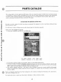
PARTS CATALOG
another free manual from www.searstractormanuals.com
This cat alog applies to tractor application BF En gi nes. Parts are arran ged in groups of related items. Each illu strated part
is ide ntifi ed by a re ference numbe r corr es ponding to the s ame reference number follo wing the illu stration . Parts i llu stration s
are typica l. Unless otherwise mention ed in the desc ription, part s are interchangea bl e between mode l s . Right and le ft
sides are determined by facing the blower end (front) of the engine .
INSTRUCTIONS FOR ORDERING REPAIR PARTS
For part s or service, contact the dea ler from whom you purchased this equipment or re fer to your Nearest Auth orized On an
Parts and Service Cente r.
To avoid errors or de lay in filling your parts order, please furnish all information requested.
Always re fe r to the na meplate on you r unit :
1. Always give th e MODEL and SPEC NO. and SERIAL NO.
For handy re ference, in sert
namep late information in th e
YOUR
spaces
engine
above.
2. 00 not order by refe rence number or group numbe r, always use pa rt number and de sc ription.
3. Give the part numbe r, description and quantity needed of each it e m. If an olde r part cannot be identified, return the part
pr e paid to your dea ler or nearest AUTHORIZED SERVICE STATION . Print your name and addr ess plainly on the package.
Write a letter to the same address stating the reason for returnin g the part.
4. Sta te definite s hippin g instruc tion s . Any cla im for loss o r d amage to your unit in tran s it s hould be fil ed promptly
agai ns t the trans porta tion company making th e de live ry. Shipment s are complete un les s the pac king list indicates items
ar e back ordered.
Prices are purposely omitt ed from thi s Parts Catalog due to th e confusion res ultin g from fluctu atin g c osts, import duties,
s ales taxes, ex change rate s , etc .
For current parts prices, c onsult your Onan Deale r, Distributor or P arts and Service Center.
29
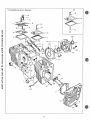
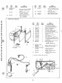
CYLINDER BLOCK GROUP
~-6
another free manual from www.searstractormanuals.com
r
7
'3
0---
t-
5
'~-6
20
~'--7
16-.--21
8
17
19
26
30
g
REF.
PART
QTY.
.J:iSL.
...!:!.Q.:..
J!.illt
110-1975
2
3
4
5
another free manual from www.searstractormanuals.com
6
7
8
9
10
I I
12
13
14
15
16
17
18
19
20
21
123-1174
123-1175
123-1173
WASHER. FLAT
526-0018
I
526-0063
2
PART
DESCRIPTION
REF.
PART
.1i2.:.
-1i!L
22
Block Assembly. Cyl inder
(Includes Parts Marked t)
Spring, Breather Valve
Valve. Breather
Baffle. Breather
Breather Valve (1/4" - Steel)
Valve Compartment Cover
(1/4" Copper)
526-0122
18
Cylinder Head Screws
(5/16" - Steel)
COVER. VALVE COMPARTMENT
110-1878
I
Cover with Opening for
Breather Tube (L.H.)
110-1879
Cover without Opening for
Breather Tube (R.H.)
110-1921
3
Gasket, Valve Cover
517-0048
I
tPlug. Camshaft Expansion
STUD
520-0424
6
Cylinder Head (5/16 x 2-5/16")
520-()759
12
Cylinder Head (5/16 x 2-1/16")
520-0757
2
Valve Cover (1/4x2-1/16")
Spec A Through C
104-()776
As Req. tSh i m. Rear Bear ing Plate (.005 ")
110-1920
2
Gasket. Cylinder Head
HEAD, CYLINDER
110-1924
I
Right Side (#2 Cylinder)
110-1925
I
Left Side (#1 Cylinder)
SCREW,HEXCAP
800-0051
5
tBearing Plate Mounting
(3/8-16 x I_114°)
800-()010
2
Valve Cover (1/4-20 x H/4")
Begin Spec D
123-1176
I
Tube, Breather
BEARING, CRANKSHAFT - REAR
101-()420
I
tStandard
101-0420-02
I
.002" Undersize
101-0420-10
I
.010"Undersize
101-0420-20
I
.020" Undersize
101-0420-30
I
.030" Unders ize
104-()575
2
t'Washer, Crankshaft Bearing
Thrust
101-0415
tGasket. Bearing Plate
101-0439
tPlate. Bearing (Excludes
Bearing)
101-0405
2
tBearing, Camshaft (Precision)
509-0041
I
tSeal, Bearing Plate
516-0072
4
tPin, Main Bearing Stop
31
23
24
25
26
27
28
29
30
31
32
33
34
35
36
37
t
QTY.
USED
NUT
I 10-0445
18
866-0001
2
110-0893
4
TAPPET, VALVE
I 15-0006
4
II 5-oo06-() I
4
115-0oo6-()2
4
115-0006-05
4
850-0050
5
PART
DESCRIPTION
Cy I inder Head - Hex
(5/16-24 )
Valve Cover Acorn
(1/4-20) -SpecAThroughC
Retainer. Valve Spring
Standard
.001" Oversize
.002" Oversize
.005" Overs ize
tWasher, Lock (3/8") - Rear
Bearing Plate
tTube. Crankcase Oi I
120-0706
VALVE
I 10-1808
2
Intake
110-1809
2
Exhaust
INSERT, VALVE SEAT - EXHAUST
I 10-()245
2
tStandard
1I0-()245-02
2
.002" Oversize
110-0245-05
2
.005" Oversize
110-()245-10
2
.010" Oversize
110-0245-25
2
.025" Oversize
INSERT, VALVE SEAT - INTAKE
Ii 0-0 197
2
tStandard
110-0197-02
2
.002" Oversize
110-0197-05
2
.005" Oversize
II 0-0197-1 0
2
.010" Overs ize
110-0197-25
2
.025" Oversize
110-1807
4
tGuide.Valve
I 10-()539
4
Spring. Valve
I 10-()639
8
Lock, Valve and Spring
Retaining
'BEARING, CRANKSHAFT - FRONT
101-0432
I
tStandard
101-0432-()2
I
.002" Undersize
10 1-()432-1 0
I
.010" Unders ize
101 -0432-20
J
.020" Unders ize
101-()432-30
I
.030" Unders ize
806-0027
2
Screw, Hex Head Cap (3/8-16
x 314") - Cylinder Block
526-0066
2
Washer (3/8 Copper) Cylinder Block
110-0068
2
f'Gasket, Valve Guide (Intake)
517-0120
I
:Plug, Breather Hole
-Included in Cylinder Block Assembly.
• .. Replacement front flange. bearing replaces
unflanged bearing and thrust washer.
3
(0)
21
10
another free manual from www.searstractormanuals.com
27
8
'.
,
,-22
9
~
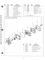
GEAR COVER, OIL BASE AND
OIL PUMP GROUP
32
REF.
NO.
another free manual from www.searstractormanuals.com
2
3
4
5
6
7
8
9
10
II
PART
NO.
QTY.
USED
PART
DESCRIPTION
COVER ASSEMBLY. GEAR (Inc ludes Parts
Marked ')
103-050 I
Begin Spec D
103-0409
Spec A Through C
510-0105
'Bearing. Governor Shaft
'SHAFT & ARM ASSEMBLY, GaVE RNOR
150-1470
I
Begin Spec D
150-1349
I
Spec A Through C
150-1187
I
'Yoke, Gov ernor Shaft
815-0046
2
'Screw, Yoke Retaining
516-0130
I
'Pin, Governor - Cup Stop
509-0008
I
'Seal, Oil - Governor Shaft
510-00 14
I
*Ball, Bearing - Governor Shaft
509-0040
I
'Seal, Gear Cover
103-0408
I
Gasket, Gear Cover Mounting
516-00 I I
Pin, Gear Cover (5/16 x
2
REF.
PART
QTY.
.l!2.:..
2i2.:..
~
21
22
23
24
25
26
120-0161
149-1299
Gasket Kit. Oil Pump
'Tube. Fuel Pump Vacuum
WASHER. LOCK
850-0050
850-CXHO
122-0359
122-0321
4
2
I
I
2
526-0066
526-0065
5
123-1138
102-0693
505-0056
102-0730
120-0140
801-0050
18
19
120-0398
120-0491
20
120-0713
I
I
2
I
I
I
Cap and Indicator, Oil Fill
Gasket. Oil Base Mounting
Plug, Oil Drain
Base, Oil
Spring, Oi I By-Pass Valve
Screw, Oi I By-Pass
(318-24 x 1°)
Valve, Oi I By-Pass
Pump, Oil - Complete
(Note: Internal parts not
sold se parate Iy)
Intake. Oil Pump (Includes:
Cup, Screen, and Pipe)
Oil Filter Pad Cover Mounting
(5/16")
Oil Pressure Relief Valve
Screw (Copper - 3/8")
Gear Cover Mounting
(Copper - 5/16//)
SCREW, HEX CAP
800-0026
2
800-0056
4
800-0032
4
1-1/8")
12
13
14
15
16
17
Oil Base Mounting (3/8")
Oil Pump Mounting (1/4")
Cover, Oil Filter Pad
Gasket, Oil Filter Pad Cover
WASHER, FLAT
526-0122
27
PART
DESCRI PTION
800-0034
800-0007
2
Oil Filter Pad Cover Mounting
(5/16-18 x 3/4")
Oil Base to Block (3/8-16 x
2-1/2//)
Gear Cover Mounting (5/16-18
x 1-3/4")
Gear Cover Mount ing (5/16-18
x 2-1/4")
Oil Pump Mounting (1/4-20 x I 0)
• - Included in Gear Cover Assembly.
33
another free manual from www.searstractormanuals.com
6
27
24
15
13-11
26
CRANKSHAFT. FLYWHEEL. CAMSHAFT
AND PISTON GROUP
REF.
NO.
I
2
3
4
5
6
PART
NO .
150-0078
150-1116
510-0015
104-0779
134-243 2
QTY .
USED
I
I
5
I
I
PART
DESCRIPTION
105-0332
104-0032
Gear. Camshaft
Gear, CrankshaU
7
105-0004
Was her, C amshaft Gear
Thrust
8
KEY
515-0001
10
II
13
14
Ring . Camsh aft Center Pin
Cu p. Governor
Ba II. Fly· Governor
Gear. Ring - Flywheel
F Iywhee I (Inc ludes Ring Gear
and Magnet Ring)
6A
9
REF.
~
15
QTY,
PART
DESCRIPTION
~
518-031 I
4
Ring. Pi Ston Pin Re t aining
ROD ASSEMBLY. CONNECTING
I 14-0225
2
Stand ard
114-0225-10
2
.010 " Undersize
114-0225-20
2
.020" Unders ize
114-0225-30
2
.030 " Unders ize
RING SET, PISTON
113 -0174
2
Stand ard
113-0174-05
2
.005 " Oversize
.010 " Ove rsize
113 -0174-10
2
.020
Oversize
113 -0174-20
2
.030 " Oversize
I 13 -0174 -30
2
.040 " Oversize
113-0174-40
2
114-0228
4
Bolt . Conne c t in g Rod
( Special)
Washer (7 ! 16 " ) - F Iywhee I
526 -0 017
Mounting
870-0137
4
Nut. Lo ck ing - Connecting
Rod C a p
Washer. Lock (7 ! 16 " )
850-0055
Fl ywheel Mounting
Guar d , F Iywhee I
134-2384
104-0170
Screw. He x Cap
(7 / 16 - 14x4")Flywheel
Mounting
Lock , Crankshaft Ge ar Wa sher
518-0014
Washer. Cr a nkshaf t Ge ar
104-0043
Retaining
U
2
Cam shaft Gear Mount ing ( I)
Cranks haft Gear Mounting (I)
Flywheel M ou nting - Begin
515-0098
Spec D (Use with 104-0889
Camshaft Only)
Flywheel M ounti ng - Spec A
515-0002
Through C ( Use with
104-0763 C amshaft Only)
C a mshaft (Includes Center
105-0388
Pin)
150-0075
I
Pin. Cams ha ft Center
PISTON AND PIN (INCLUDES RETAINING RINGS)
I 12-0134
2
Standard
2
,005
Over size
I 12-0134 -0 5
2
.010 " Overs ize
112-0134-10
2
.020 " Oversize
112 -0134 -20
2
,030 " Ove rsiz e
112-0134 -30
2
.040 " Ove rs ize
112-0134-40
112-0122
2
Pin. Piston
16
17
18
19
20
21
U
12
PART
NO.
34
23
24
"E F.
NO.
25
PART
NO.
oJ.TY.
~ART
~
DESCRI PTI ON
CRANKSHAFT
104-0889
Begin Spec D (Use 515-0098
Flywheel Mounting Key
Only)
Spec A Through C ( Use
515-0002 Flywheel
Mounting Key Only)
Screw. Locking (1/4-20 x
112 " ) F Iywhee I
Guard Mounting
104-0763
2h
821-0010
REF .
NO .
3
27
821-00 14
28
515-0103
29
30
150-1257
150-0077
PART
DESCRIPTION
QTY.
USED
PART
NO .
2
Screw, Locking (5 / 16 - 18
x 112 ") Flywheel Guard
Mounting
Key (114 x 1/ 4x2 " )
Cran kshaft Stub
Spacer, Governor F Iyball
Plate, Governor F Iyba II
another free manual from www.searstractormanuals.com
IGNITION GROUP
REF.
NO.
PART
NO.
QTY .
USED
160-1158
17~
2
18
2
3
4
6
7
8
9
10
II
12
13
14
160-1 148
503-03 II
160-1154
312-0069
167 -0188
160-1150
160-1149
160-1151
167-1463
166-0535
167-1462
815-0358
I
2
15
16
17
167-0241
336-2132
802-0034
2
I
2
18
WASHER, LOCK
850-0038
2
850-0025
I
SCREW, PAN HEAD
815-0403
I
19
815-0405
20
870-0221
PART
DESCRIPTION
Box Assemb Iy, Breaker
(Includes Parts Marked .)
'Gasket, Breaker Box Co ver
Clamp, Coi I Mounting
• P o int Set, Breaker
'Condenser, Breaker Points
Clip, Spark Plug Cable s
Ga s ket. Breaker Box Mounting
·Cover . Breaker Box
Plunger
C a ble. Spark Plug (19 " )
Co i l, Ign i tion
Cable. Spark Plug (16-3 / 4 " )
'Screw, Pan Head (8-32 x 5 / 16 " )
- Breaker Box Cover Mounti ng
Plug, Spark
·Lead Assembly, Po i n t s to Coil
·Screw, Socket Head
(1 / 4-20 x 3/ 4 " )
Breaker Box Mounting
·BreaKer Box Mounting(1 / 4 ")
'Condenser Mounting ( #8)
'Condenser Mounting
(8-32 x 5/16 " )
• Breaker Points Mounting
(8-32 x 112 ")
'Nut (#8) - Breaker Points
Mounting
• - Inc luded in Breaker Box Assembl y .
13
6
18-19
11
5
19-20
35
another free manual from www.searstractormanuals.com
20
3
25
7
~-
I
"'
~
I
"
0---
~6
3
I
24
1
.6il
10
FUEL SYSTEM
GROUP
36
..
....
5
5
REF.
NO.
PART
NO.
. QTY.
USED
another free manual from www.searstractormanuals.com
140-1169
I 42...()SS8
I
I
I
2
3
4
5
6
145-0438
154-1468
154-1446
520-0758
7
8
140-1198
862-00 15
9
10
15
503...()664
503-0663
140-1215
140-1213
140-1216
140-1168
865-0020
16
17
SCREW, HEX CAP
II
12
13
14
505"'()086
8oo"()008
2
4
4
2
2
PART
DESCRIPTION
Tube, Air Intake(Air Cleaner
to Blower Housing)
• Carburetor
Gasket, Carburetor Mounting
Manifold, Intake
Gasket, Intake - Manifold
Stud (5/16-18 x 2-1/2 u) Intake
Manifold Mounting - Spec A
4
18
PART
NO.
QTY .
USED
PART
DESCRIPTION
WASHER, LOCK
850-0040
850"'()045
2
4
19
815"'()377
3
20
22
23
24
140-1218
149-1322
518-0328
809"'()045
2
2
25
8oo"'()003
26
27
29
30
862-0001
853-0013
149-1321
503-0301
Carburetor Mounting (1/4")
Intake Man ifold Mounting
(5/16")
Support, Air Cleaner Through C
Nut, (5116-18) Intake
Manifold Mounting - Spec
A Through C
Hose, F ue I Pump to Carburetor
Hose, Fuel Pump Vacuum
Gasket, Air Cleaner Mounting
Housing, Air Cleaner
Element, Air Cleaner
Cover, Air Cleaner
Nut, Wing (1/4-20) - Air Cleaner
Cover
Nipple, (I" x 2-1/2") -Exhaust
I
I
I
I
3
Screw, Round Head (10-32 x 3/8")
- Air Cleaner Housing Mounting
Wrapper, Air Cleaner Element
'Pump, Fuel
Clip, Bracket - Choke Cable
Screw, Sheet Metal - Fuel Pump
Mounting (#10 x Sl8")
Screw, Hex Cap (1/4-20 x 1/2°) _
Support to Air Cleaner
Nut, Hex. (1/4-20)
Washer, Lock (1/4")
Cap, Fuel Pump
u
Clamp, Hose (7/16 )
• - See separate group for components.
Carburetor Mountin
(1/4-20 x 1-114
800..Q034
REF.
NO.
h)
Intake Manifold Mounting
(5/16-18 x2-1/4") Begin
Spec 0
37
CARBURETOR PARTS GROUP
G,g
. . . - -___ '0
5
another free manual from www.searstractormanuals.com
I
I
~~
____ 2
14
13
21~
22
j)
6~
16
~4
\~
~~
12
11
15
7
38
3
another free manual from www.searstractormanuals.com
REF.
NO.
I
2
3
4
5
6
7
8
9
10
II
12
13
14
15
PART
NO.
142-0558
I 42..()532
142-0533
142-0534
QTY.
USEQ..
I
I
142~0535
142-0536
142-0554
142-0538
142"()064
142-0334
I 42..()539
I 42..()539
142-0559
142-0553
142-0543
149-1326
4
4
2
I
I
PART
DESCRI PTIOtL,
REF.
PART
QTY.
PART
...!ill.:..
....!:!.2..:.-
~
D~S~BIPTIQ~
Carburetor Assembly. Compl ete
Body Assemb Iy, Lower
Sleeve Assembly
'Shaft, Thrott Ie
"Packing, Shaft
Shaft, Ch oke
Clip, Float Valve
Fly, Thrott Ie
Screw, Throttle Stop
'Screw, Fly Mounting
Screw, Bowl Cover Mount ing
Screw, Plate Mounting
"Gasket, Plate
'Valve Assembly, Float
' 'Gasket
Plate, Carburetor Inlet
16
17
18
19
20
21
22
23
Spr ing, Thrott Ie Stop Screw
'Spring, Idle Needle
Gasket, "0" Ring
Fly, Choke
Float and Lever Assembly
'Shaft, Float Lever
'Needle, Idle
Needle Assembly, Power
'Gasket Set (Includes Parts
Marked ")
Repair Kit (Includes Parts
Marked ')
142-0544
142-0282
142-0550
142-0546
142-0547
142-0548
I 42"()016
142-0549
142-0560
I 42"()56I
' - Incl uded in Repair Kit.
,. - Included in Gasket Set.
FUEL PUMP PARTS GROUP
2
REF.
NO.
I
2
3
4
5
6
7
8
9
39
PART
NO.
149-1322
142-0537
I 42..()540
149-1323
142-0541
142-0545
149-1326
149-1324
142-0552
142-0555
QT¥.
USED
I
I
2
PART
DESCRIPTION
Pump Assembly, Complete
Valve Plate Assembly
Screw, Pump Cover
Gasket, Cover to Valve Plate
Gas ket, Base to Diaphragm
Spring, Pump Diaphragm
Cover, Pump
Base, Pump
Plate, Pump Spring
Diaphragm. Pump
another free manual from www.searstractormanuals.com
STARTING MOTOR PA RTS GROUP - SPEC A ONLY
3
7
REF.
NO.
I
2
3
4
5
6
7
8
9
40
PART
NO.
191-0883
191-0906
191-0907
191-0908
191-0909
191-0910
191-0911
191 -0912
191 -09 13
191-0917
QTY.
USED
I
I
I
I
I
I
2
I
I
2
PART
DESCRIPTION
Motor. Startin (
Housing A
g Complete)
Cap Assembly
ssembl
Armature A y. End
Cap Assembly
ssembl y, Drive End
Drive A
ssembl
Bolt Assembl y (Complete)
Brush (1)
y, Through
Brush (-)
Spring, Brush
7
0)
8
\
9?'1ro~~
1
2
3
4
5
~---
11
0
\
/
6
!
another free manual from www.searstractormanuals.com
/
STARTING MOTOR PARTS GROUP - BEGIN SPEC B
REF.
NO.
I
2
3
4
5
6
7
8
9
10
II
12
PART
NO.
191-0933
191-1034
191-1045
191-1046
191-1035
191-1047
191- 1036
191-1048
850-{) 040
191-1037
191-1038
191-1039
13
14
£.
£.
£.
15
16
£.
£.
17
£.
18
19
20
21
£.
£.
£.
£.
22
191-1040
23
£.
191-1041
QTY.
USED
I
I
I
I
I
I
2
2
I
I
I
4
I
2
2
PART
DESCRIPTION
Motor, Starting (Complete)
Cover, Dust
Nut, Stop
Washer, Stop Nut
Spring, Anti-drift
Spacer, Dus t Cover
Dr ive Assemb Iy
Screw, Hex Cap - Starter
Through
Washer, Lock
Cap Assembly, Drive End
Washer, Armature Thrust
Armature
t*Spring, Brush
tBrush Holder
tScrewand Lockwasher - Brush
and Brush Holder Mounting
t*Brush. Ground
t *Stud and Brush Assemb Iy,
Input
"lBushing, Insulation - Input
Stud
tWasher, Insulation - Input Stud
tWasher. Flat - Input Stud
tWasher. Lock - Input Stud
tNut. Securing - Input Stud
Cap Assemb Iy, Commutator
(Includes Parts Marked t)
Hous ing, Starter Motor
Repair Kit. Brush, Spring and
Stud (Includes Parts
Marked *)
t
-Included in the 191-1040 Cap Assembly.
Included in the 191-1041 Brush, Spring and Stud Kit.
£. - Not Sold Separately.
* -
41
GOVERNOR, STARTER, CHARGING ALTERNATOR
another free manual from www.searstractormanuals.com
AND BLOWER HOUSING GROUP
10
REF.
NO .
1
2
3
4
5
6
7
8
9
10
II
12
13
14
15
9
PART
NO.
QTY.
USED
PART
DESCRIPTION
REF.
~
150-1350
I
Rod. Governor Control
CLI p. GOVERNOR CONTROL ROD
5 18-0004
I
Carb uretor End
870-0278
I
Governor End
134-2382
Housing. Cylinder Air - Left
134-2393
Hous ing. Blower
134-2383
Hous ing. Cylind er Air - Right
MOTOR. STA RTING (For Components - See Separ ate
Group)
191-0883
Spec A Only
191 -09 33
Beg in Spec B
191-0935
I
St ator. Chargin g Alternat or
SCR EW. HEX HEAD ( 1/ 4-20 x 7/ 16°)
815-026 1
3
Blowe r Housing Mounting
815 -026 1
4
Cyl inder Air Hous ing Mounting
150-1345
Arm. Governor Control
150-1343
Bra cket. Governor Mounti ng
150-1398
Spring. Throttl e L ev er Adjusting
Sc rew
152 -0155
Swive l. Throttl e Cable
5 16-0059
Pin. Cotter - Swive l Moun t ing
518-0176
CliP. Throttle C ab le
150 -1269
Bushing. Go vernor Contro l
16
17
PART
NO.
QTY.
J!gQ
150-1 214
SCREW. ROUND
813-0108
812-0066
815 -0104
18
19
20
42
I
Spring , Gover nor
HEAD
Stat or Mounting ( 10-32 x 1-1 /2" )
3
I
Thrott le Lever A djusting
(6-32 x 3 / 4")
Cable Lock - Sw ivel
(8-32 x 5 / 16 " )
WASHER. LOCK
850-0040
2
850-0030
3
850-0045
2
SCREW. H EX CAP
800-0028
2
821-0010
WASHER. FLAT
526-0006
526 - 0214
526-0113
21
191 ..('18 86
22
332 0051
0
PART
DESCRIPTION
2
Governor Contro l Mount ing
(1 1 4 ° )
Stator Mounting (1-'10)
Starter Motor Mounting (5/16 " )
Starter Mo tor Mount ing
(5/ 16-18 x 1 ° )
Governor Control Mounting
(1/4-20 x 112 " )
Swive l Mounting
Governor C on trol Mounting
Starter Motor Mounti ng
(T op Hol e)
Regu lat ar , Rect if ier
Cl i p, Fue l Hose
SERVICE KITS AND MISCELLANEOUS
another free manual from www.searstractormanuals.com
REF.
NO.
PART
NO.
168-0123
168-0124
522-0266
QTY.
USED
PART
DESCRI PTION
Gasket Kit, Carbon Removal
Gasket Kit, Engine
Overhaul Kit
43
another free manual from www.searstractormanuals.com
MOUNTED BEHIND
BLOWER WHEEL
VOLT
REG.
RECT.
CAUTION'
REGULATOR MUST BE GROUNDED
THROUGH MOUNTING BOLTS
AC AC B+
'FUSE 35AMP
'AMMETER
(OPTIONAL)
'DISCONNECT
SWITCH
(OPTIONAL TO ELIMINATE
• '2S MA LEAKAGE ON SHUTDOWN)
'START
SWITCH
~
____________
r---
BREAKER AND
CAP ASSEMBLY
~~S
'IGNITION
SWITCH
~
IGNITION
0 L
~~----~7 O~------+-~~---------I--Jt9-~~:
n
STARTER
I
'BATTERY
12 VOLT
, • FURNISHED BY CUSTOMER.
ENGINE WIRING DIAGRAM
44
J
l! __ :J
SPARK
PLUGS
another free manual from www.searstractormanuals.com
another free manual from www.searstractormanuals.com
I
,!
I .
ONAN
1400 73RD AVENUE N.E. • MINNEAPOLIS, MINNESOTA 55432
A DIVISION OF ONAN CORPORA TION